taw, tpw type - tungaloy corporation the customer first screw clamped milling cutter tungaloy report...
TRANSCRIPT

Keeping the Customer First
Screw clamped milling cutter
Tungaloy Report No. 358-US
The best solution for steel and cast iron milling!
TAW, TPW type
2
YC
XC
ZC
TAW13
■■30
25
20
15
10
5
0
(ft)
8"
4"
2500
2000
1500
1000
500
0
(N)
0 .002 .004 .006 .008 .010 .012 .014
Ymax
Zmax
TAW13
27˚
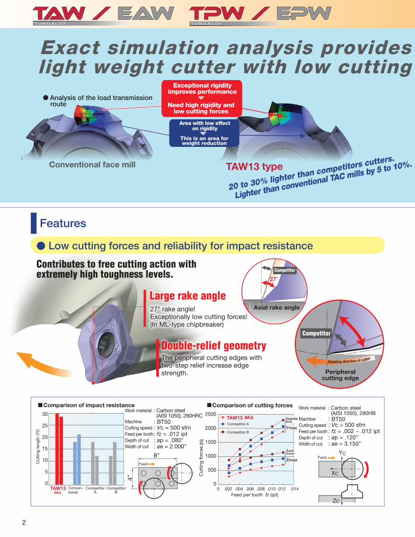
: BT50: Vc = 500 sfm: fz = .012 ipt: ap = .080": ae = 2.000"
: BT50: Vc = 500 sfm: fz = .002 ~ .012 ipt: ap = .120": ae = 3.150"
TAW13
Exact simulation analysis provides light weight cutter with low cutting ● Analysis of the load transmission route
Exceptional rigidity improves performance
Need high rigidity and low cutting forces
Area with low effect on rigidity
This is an area for weight reduction
typeConventional face mill
20 to 30% lighter than competitors cutters.
Lighter than conventional TAC mills by 5 to 10%.
Features
Large rake angle27° rake angle!Exceptionally low cutting forces!(In ML-type chipbreaker)
Double-relief geometryg ygThe peripheral cutting edges with two-step relief increase edge strength.
Competitor
Axial rake angle
Peripheralcutting edge
Rotating direction of cutter
Competitor
Comparison of impact resistanceWork material
MachineCutting speedFeed per toothDepth of cutWidth of cut
Conven-tional
CompetitorA
FeedCut
ting
leng
th
CompetitorB
: Carbon steel (AISI 1050), 280HRC
Comparison of cutting forces
Cut
ting
forc
es
Feed per tooth
Tangential force
Axialforce
Competitor A
Competitor B
(MJ)
fz (ipt)
Feed
� Low cutting forces and reliability for impact resistance
Work material
MachineCutting speedFeed per toothDepth of cutWidth of cut
: Carbon steel (AISI 1050), 280HB
Contributes to free cutting action with extremely high toughness levels.
(MJ)

3
.08"
30º
fz
.08"45º
fz
.560
.480
.400
.320
.240
.160
.080
0
■
4"
-.004 -.002 0 .002
CA 45º
: BT50: Vc = 330 sfm: fz = .004 ipt: ap = .120" ×: ae = 4"
.600"
TPW13
a highly rigid, forces !!
� High productivityBodies are available in coarse, close, and extra-close (made to order) pitch design.TAW13 type with 45° corner angle. HJ-type inserts for high feed milling are available.
The HJ-type insert with a 30° cutting edge angle can reduce cutting load. Furthermore, the HJ-type allows feed rates to be improved 2 times.
Productivity improvedX 2 times!
HJ-type
� High accuracyThe body has a highly improved axial and radial run-out that can drastically improve surface quality.TPW / EPW13 type with a 90° corner angle creates highly accurate wall straightness.
Accuracy of wall straightness produced with 90° corner angle cutters.
Wall straightness (in)
Mea
surin
g he
ight
: ap
(in)
Competitor A
Competitor B
Work material
Machine Cutting speedFeed per toothDepth of cutWidth of cut
: Carbon steel (AISI 1055), 210HB
ap = .120" × 5 passes
Feed
� Highly functional body designAir-holes applicable for through-the-spindle coolant system. (For cutters smaller than ø 5.000".)Special surface treatment improves resistance to corrosion and rubbing.
5 passes
(slot milling)(MJ)

4
Ra Rz RZJIS
■ ■
■
YC
XC
ZC
■ ■
AH130
T1115
2000
1500
1000
500
00.00 .002 .004 .006 .008 .010
TPW13
(N) Yc max
15
10
5
0TPW13
.020
.016
.012
.008
.004
010 20 30 40
TAW13
.060
.040
.020
0
(in)
Zc max
: BT50: Vc = 500 sfm: fz = .002 ~ .008 ipt: ap = .120": ae = 3.150"
: BT50: Vc = 500 sfm: fz = .008 ipt: ap = .120": ae = 2.000"
DS1100
3
2
1
0 TAW13TAW13
T U N G A LOY
T U N G A LOY
AH120 :T3130 :NS740 :
KS05FDS1100
200
150
75
ø100
ø100
Chipbreaker
MJ typeFor general purpose well balanced impact resistance and low cutting forces.
for general purpose. for high speed milling. for high quality surface fi nish.
Cast Iron
StainlessSteel
Cutting forces Impact resistance
Competitor A
Conventional
Competitor B
(MJ insert)
Cut
ting
forc
e
Feed per tooth: fz (ipt)
Work material MachineCutting speedFeed per toothDepth of cutWidth of cut
: Carbon steel (AISI 1055)
Tangential force
Axialforce
Feed
Work material MachineCutting speedFeed per toothDepth of cutWidth of cut
: Die steel (PX5)
(MJ)Conven-tional
CompetitorA
Cut
ting
leng
th
Max
imum
wea
r w
idth
Cutting length
VB
max
(in)
(MJ insert, AH120)Competitor A(PVD coated)Competitor B(CVD coated)Competitor C(CVD coated)
Work material
Machine Cutting speedFeed per toothDepth of cutWidth of cut
: Chromium molybdenum steel equivalent to AISI 4140, 280HB: BT40: Vc = 500 sfm: fz = .010 ipt: ap = .080": ae = 2.500"Dry cutting
Wear resistance
For machining aluminum alloysAJ type
Excellent sharpness with the AJ chipbreaker
Excellent welding resistance
DLC coated grade
The DLC coated grades offer excellent welding resistance.
Longer tool life, Better surface fi nish &
fewer burrs!!
: General purpose : High surface quality
Burr height Surface fi nish
feed direction cutting direction
Bur
r he
ight
(AJ)Competitor
ACompetitor
B
Sur
face
fi ni
sh
CompetitorA
CompetitorB
Work material
MachineCutting speedFeed per toothDepth of cutWidth of cut
: Aluminum alloy (AISI 5052): BT40: Vc = 2000 sfm: fz = .006 ipt: ap = .040": ae = 3"
Burr height
Burr height
First choice
Feed
(ft)
Feed
typetype
(ft)
(µm
)
(AJ)
Non-ferrous
8"
4"
8"
ø4.000"
ø4.000"
6"3"
5
■30
20
10
0
(ft)
■
T1115AH130
NS740
GH110
AH120
T1115
TAW13
T U N G A LOYT U N G A LOY
T U N G A LOY
KS05FDX140DS1100
AH120T3130
AH120NS740
AH120T3130NS740
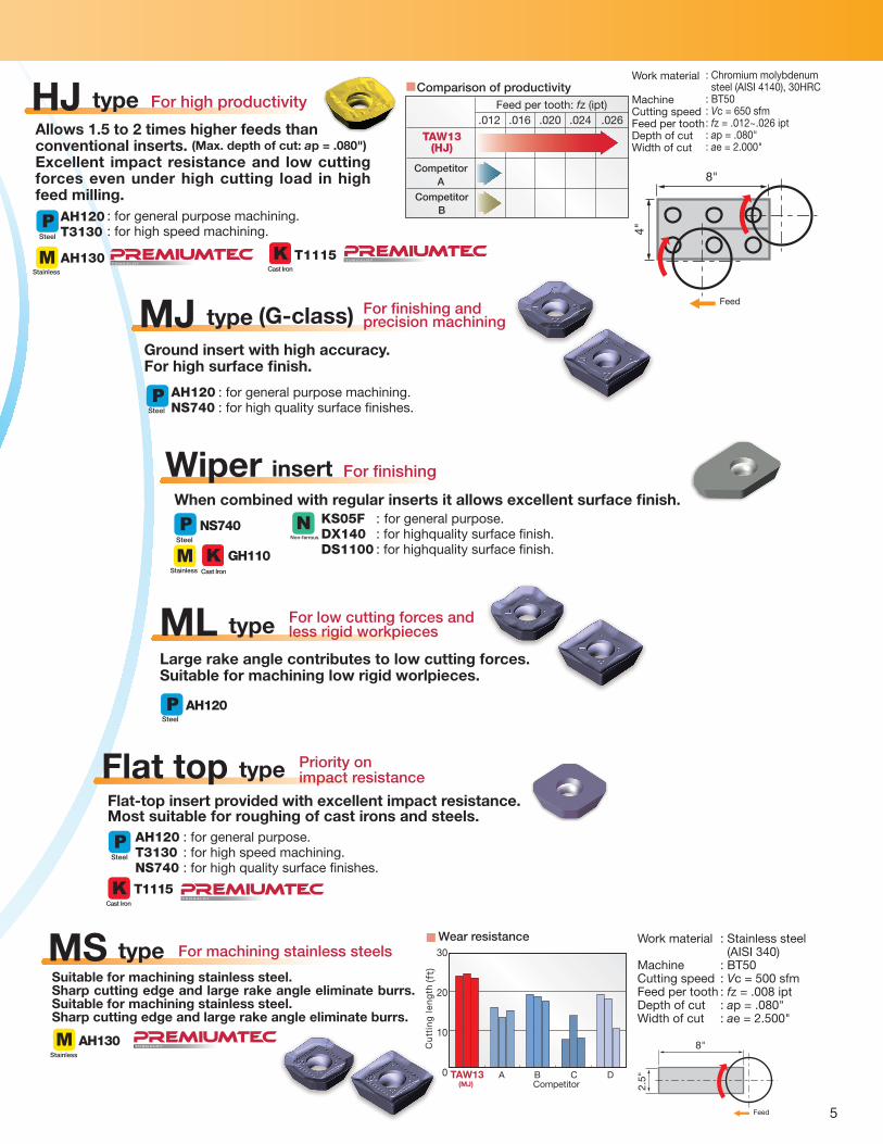
HJ type For high productivity
Allows 1.5 to 2 times higher feeds thanconventional inserts. (Max. depth of cut: ap = .080")Excellent impact resistance and low cutting forces even under high cutting load in high feed milling.
Stainless
Comparison of productivity
TAW13(HJ)
CompetitorA
CompetitorB
Feed per tooth: fz (ipt)
Work material
Machine Cutting speedFeed per toothDepth of cutWidth of cut
: Chromium molybdenum steel (AISI 4140), 30HRC: BT50: Vc = 650 sfm: fz = .012~.026 ipt: ap = .080": ae = 2.000"
FeedMJ type (G-class) For fi nishing and precision machining
Ground insert with high accuracy.For high surface fi nish.
: for general purpose machining.: for high quality surface fi nishes.
Steel
Steel
Wiper insert For fi nishing
When combined with regular inserts it allows excellent surface fi nish.
Steel
Stainless
Non-ferrous
ML type For low cutting forces andless rigid workpieces
Large rake angle contributes to low cutting forces.Suitable for machining low rigid worlpieces.
Steel
Flat top type Priority onimpact resistance
Flat-top insert provided with excellent impact resistance. Most suitable for roughing of cast irons and steels.
Steel
MS type For machining stainless steels
Suitable for machining stainless steel. Sharp cutting edge and large rake angle eliminate burrs.Suitable for machining stainless steel. Sharp cutting edge and large rake angle eliminate burrs.
Stainless
Wear resistance
Cu
ttin
g l
en
gth
Work material
MachineCutting speedFeed per toothDepth of cutWidth of cut
: Stainless steel (AISI 340): BT50: Vc = 500 sfm: fz = .008 ipt: ap = .080": ae = 2.500"
Feed
DCBA(MJ)
: for general purpose machining. : for high speed machining.
AH130T U N G A LOY
: for general purpose.: for highquality surface fi nish.: for highquality surface fi nish.
: for general purpose.: for high speed machining.: for high quality surface fi nishes.
Cast Iron
Cast Iron
Cast Iron
8"
2.5"
4"
8"
.012 .016 .020 .024 .026
Competitor
6
øda
R
L f
b
øDcøD1
45°
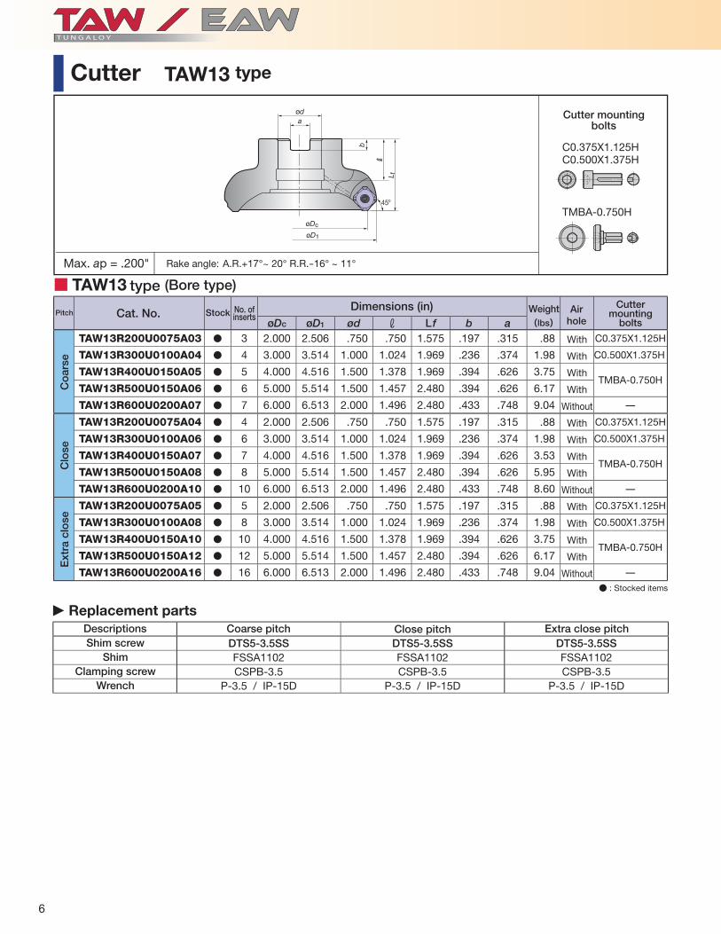
A.R.+17°~ 20° R.R.-16° ~ 11°
(lbs)øDc øD1 ød r L f b aTAW13R200U0075A03 � 3 2.000 2.506 .750 .750 1.575 .197 .315 .88 C0.375X1.125H
TAW13R300U0100A04 � 4 3.000 3.514 1.000 1.024 1.969 .236 .374 1.98 C0.500X1.375H
TAW13R400U0150A05 � 5 4.000 4.516 1.500 1.378 1.969 .394 .626 3.75TMBA-0.750H
TAW13R500U0150A06 � 6 5.000 5.514 1.500 1.457 2.480 .394 .626 6.17
TAW13R600U0200A07 � 7 6.000 6.513 2.000 1.496 2.480 .433 .748 9.04 -
TAW13R200U0075A04 � 4 2.000 2.506 .750 .750 1.575 .197 .315 .88 C0.375X1.125H
TAW13R300U0100A06 � 6 3.000 3.514 1.000 1.024 1.969 .236 .374 1.98 C0.500X1.375H
TAW13R400U0150A07 � 7 4.000 4.516 1.500 1.378 1.969 .394 .626 3.53TMBA-0.750H
TAW13R500U0150A08 � 8 5.000 5.514 1.500 1.457 2.480 .394 .626 5.95
TAW13R600U0200A10 � 10 6.000 6.513 2.000 1.496 2.480 .433 .748 8.60 -
TAW13R200U0075A05 � 5 2.000 2.506 .750 .750 1.575 .197 .315 .88 C0.375X1.125H
TAW13R300U0100A08 � 8 3.000 3.514 1.000 1.024 1.969 .236 .374 1.98 C0.500X1.375H
TAW13R400U0150A10 � 10 4.000 4.516 1.500 1.378 1.969 .394 .626 3.75TMBA-0.750H
TAW13R500U0150A12 � 12 5.000 5.514 1.500 1.457 2.480 .394 .626 6.17
TAW13R600U0200A16 � 16 6.000 6.513 2.000 1.496 2.480 .433 .748 9.04 -
DTS5-3.5SS DTS5-3.5SS DTS5-3.5SSFSSA1102 FSSA1102 FSSA1102CSPB-3.5 CSPB-3.5 CSPB-3.5
P-3.5 / IP-15D P-3.5 / IP-15D P-3.5 / IP-15D
■ TAW13
Descriptions
� Replacement parts
Shim screwShim
Clamping screwWrench
Cutter mountingbolts
Rake angle:
Cat. No.Dimensions (in)No. of
insertsStock Weight Airhole
Cutter mounting
bolts
With
With
With
With
Without
With
With
With
With
Without
With
With
With
With
Without
Co
arse
Clo
seE
xtra
clo
se
Coarse pitch Close pitch Extra close pitch
(Bore type)
Pitch
type
● : Stocked items
Cutter TAW13 type
Max. ap = .200"
C0.375X1.125HC0.500X1.375H
TMBA-0.750H

SWMT13T3AFPR-MJ SWMT13T3AFER-ML SWMW13T3AFTR SWMT13T3AFPR-HJ SWMT13T3AFPR-MS
SWGT13T3AFFR-AJ SWGT13T3AFPR-MJ WWCW13T3AFE/FR-WS WWCW13T3AFFR-WD
18º30' 18º30' 18º30' 18º30' 18º30'
18º30' 18º30' R500
18º30' R500
18º30'
T-DIA
T3130 T1115 AH120 AH130 AH140 GH110 DS1100 NS740 KS05F DX140
SWMT13T3AFPR-MJ M � � � � � �
SWMT13T3AFER-ML M �
SWMW13T3AFTR M � � � �
SWMT13T3AFPR-HJ M � � � � �
SWMT13T3AFPR-MS M � �
SWGT13T3AFFR-AJ G � �
SWGT13T3AFPR-MJ G � �
WWCW13T3AFER-WS C � �
WWCW13T3AFFR-WS C � �
WWCW13T3AFFR-WD C �
1
2
3
4
5
6
7
8
9
7
Inserts
Stocked grades
Cat. No.
Acc
urac
y
Ho
ning
Cermet Uncoated Fig.
Typ
e
Coated
With
With
With
With
With
Without
With
With
Without
Without
Reg
ular
Wip
er
Fig.6 Fig.7 Fig.8 Fig.9
Fig.1 Fig.2 Fig.3 Fig.4 Fig.5
DLC coat
● : Stocked items
.157".547"
.547
"
.079".157".547"
.547
"
.079".157".547"
.547
"
.079".157".579"
.579
"
.091".157".555"
.555
"
.079"
.157".555"
.555
"
.079".157".547"
.547
"
.079".157".756"
.504
"
.307"
.157".756"
.504
"
.307"

Vc (sfm)
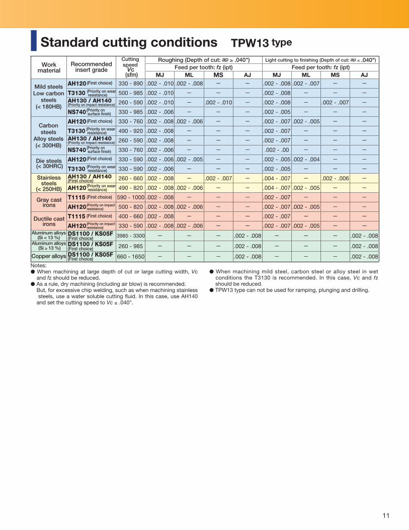
AH120 330 - 890 .002 - .012 .002 - .010 .008 - .024 - .002 - .012 -T3130 500 - 985 .002 - .012 - .008 - .024 - .002 - .012 -AH130 / AH140 260 - 590 .002 - .012 - - .004 - .010 - -
NS740 330 - 985 .002 - .009 - - - .002 - .009 -AH120 330 - 760 .002 - .010 .002 - .008 .008 - .020 - .002 - .010 -T3130 490 - 920 .002 - .010 - .008 - .020 - .002 - .010 -AH130 / AH140 260 - 490 .002 - .010 - .008 - .020 - - -
NS740 330 - 760 .002 - .008 - - - .002 - .008 -AH120 330 - 590 .002 - .008 .002 - .006 .008 - .016 - .002 - .008 -T3130 330 - 590 .002 - .008 - .008 - .016 - .002 - .008 -AH130 / AH140 260 - 660 .004 - .010 - .008 - .020 .004 - .008 - -
AH120 490 - 820 .004 - .010 .004 - .008 .008 - .020 - .004 - .010 -T1115 590 - 1000 .002 - .010 - .008 - .024 - .002 - .010 -AH120 500 - 820 .002 - .010 .002 - .008 .008 - .024 - .002 - .010 -T1115 400 - 660 .002 - .010 - .008 - .024 - .002 - .010 -AH120 330 - 590 .002 - .010 .002 - .008 .008 - .024 - .002 - .010 -DS1100 / KS05F 985 - 3300 - - - - - .002 - .008
DS1100 / KS05F 260 - 985 - - - - - .002 - .008
DS1100 / KS05F 660 - 1650 - - - - - .002 - .008
Vc (sfm)
AH120 330 - 890 .002 - .010 .002 - .008 .008 - .024 - .002 - .010 -T3130 500 - 985 .002 - .010 - .008 - .024 - .002 - .010 -AH130 / AH140 260 - 590 .002 - .010 - - .002 - .008 - -
NS740 330 - 985 .002 - .008 - - - .002 - .008 -AH120 330 - 760 .002 - .008 .002 - .006 .008 - .020 - .002 - .008 -T3130 490 - 920 .002 - .008 - .008 - .020 - .002 - .008 -AH130 / AH140 260 - 490 .002 - .008 - .008 - .020 - - -
NS740 330 - 760 .002 - .007 - - - .002 - .007 -AH120 330 - 590 .002 - .007 .002 - .005 .008 - .016 - .002 - .007 -T3130 330 - 590 .002 - .007 - .008 - .016 - .002 - .007 -AH130 / AH140 260 - 660 .004 - .008 - .008 - .020 .004 - .007 - -
AH120 490 - 820 .004 - .008 .004 - .007 .008 - .020 - .004 - .008 -T1115 590 - 1000 .002 - .008 - .008 - .024 - .002 - .008 -AH120 500 - 820 .002 - .008 .002 - .007 .008 - .024 - .002 - .008 -T1115 400 - 660 .002 - .008 - .008 - .024 - .002 - .008 -AH120 330 - 590 .002 - .008 .002 - .007 .008 - .024 - .002 - .008 -DS1100 / KS05F 985 - 3300 - - - - - .002 - .008
DS1100 / KS05F 260 - 985 - - - - - .002 - .008
DS1100 / KS05F 660 - 1650 - - - - - .002 - .008
8
Work material Recommendedinsert grade
Roughing (Depth of cut: ap ≥ .040")Feed per tooth: fz (ipt)Cutting speed
MJ ML HJ MS Flat top AJ(First choice)
(Priority on wear resistance)
(Priority on impact resistance)
(Priority on surface fi nish)
(First choice)
(Priority on wear resistance)
(Priority on impact resistance)
(Priority on surface fi nish)
(First choice)
(Priority on wear resistance)
(First choice)(Priority on wear resistance)
(First choice)
(Priority on impact resistance)
(First choice)
(First choice)
(First choice)
Mild steelsLow carbon
steels(< 180HB)
Carbon steelsAlloy steels(< 300HB)
Die steels (< 30HRC)
Stainless steels (< 250HB)
Gray cast irons
Aluminum alloys(Si < 13 %)
Aluminum alloys (Si ≥ 13 %)
Copper alloys
Work materialRecommended
insert gradeCutting speed
MJ ML HJ MS Flat top AJ
Light cutting to fi nishing (Depth of cut: ap ≤ .040")Feed per tooth: fz (ipt)
Notes:� When machining at large depth of cut or large cutting width, Vc and fz should be reduced.� As a rule, dry machining (including air blow) is recommended. But, for excessive chip
welding, such as when machining stainless steels, use a water soluble cutting fl uid. In this
Mild steelsLow carbon
steels(< 180HB)
Carbon steelsAlloy steels(< 300HB)
Die steels (< 30HRC)
Stainless steels (< 250HB)
Aluminum alloys(Si < 13 %)
Aluminum alloys (Si ≥ 13 %)
Copper alloys
(First choice)
(Priority on wear resistance)
(Priority on impact resistance)(Priority on surface fi nish)
(First choice)
(Priority on wear resistance)
(Priority on impact resistance)
(Priority on surface fi nish)
(First choice)
(Priority on wear resistance)
(First choice)(Priority on wear resistance)
(First choice)
(Priority on impact resistance)
(First choice)
(First choice)
(First choice)
Standard cutting conditions TAW13 type
case, use AH140 and set the cutting speed to Vc ≤ .040". � When machining mild steel, carbon steel or alloy steel in wet conditions the T3130 is
recommended. In this case, Vc and fz should be reduced.� TAW13 type can not be used for ramping, plunging and drilling.
Ductile cast irons(First choice)
(Priority on impact resistance)
Gray cast irons
Ductile cast irons

A.R.+11.5° R.R.-13° ~ 10.5°
(lbs.)øDc ød r Lf b aTPW13R200U0075A03 � 3 2.000 .750 .750 1.575 .197 .315 .66 C0.375X1.125H
TPW13R300U0100A04 � 4 3.000 1.000 1.024 1.969 .236 .374 1.76 C0.500X1.375H
TPW13R400U0150A05 � 5 4.000 1.500 1.378 1.969 .394 .626 3.53TMBA-0.750H
TPW13R500U0150A06 � 6 5.000 1.500 1.457 2.480 .394 .626 5.51
TPW13R600U0200A08 � 8 6.000 2.000 1.496 2.480 .433 .748 7.94 -TPW13R200U0075A04 � 4 2.000 .750 .750 1.575 .197 .315 .66 C0.375X1.125H
TPW13R300U0100A06 � 6 3.000 1.000 1.024 1.969 .236 .374 1.54 C0.500X1.375H
TPW13R400U0150A07 � 7 4.000 1.500 1.378 1.969 .394 .626 3.31TMBA-0.750H
TPW13R500U0150A08 � 8 5.000 1.500 1.457 2.480 .394 .626 5.29
TPW13R600U0200A12 � 12 6.000 2.000 1.496 2.480 .433 .748 8.16 -TPW13R200U0075A05 � 5 2.000 .750 .750 1.575 .197 .315 .66 C0.375X1.125H
TPW13R300U0100A08 � 8 3.000 1.000 1.024 1.969 .236 .374 1.76 C0.500X1.375H
TPW13R400U0150A10 � 10 4.000 1.500 1.378 1.969 .394 .626 3.31TMBA-0.750H
TPW13R500U0150A12 � 12 5.000 1.500 1.457 2.480 .394 .626 5.51
TPW13R600U0200A15 � 15 6.000 2.000 1.496 2.480 .433 .748 8.16 -
DTS5-3.5SS DTS5-3.5SS DTS5-3.5SS
FSSP1102 FSSP1102 FSSP1102
CSPB-3.5 CSPB-3.5 CSPB-3.5
P-3.5 / IP-15D P-3.5 / IP-15D P-3.5 / IP-15D
øDc
ød
L f
a
b
90º
R C
■ TPW13
9
Cutter mountingbolts
Rake angle:
Cat. No.Dimensions (in)No. of
insertsStock Weight Airhole
Cutter mounting
bolts
Co
arse
Clo
seE
xtra
clo
se
� Replacement parts
Shim screw
Shim
Clamping screw
Wrench
Coarse pitch Close pitch Extra close pitch
With
With
With
With
Without
With
With
With
With
Without
With
With
With
With
Without
(Bore type)
Descriptions
Pitch
type
● : Stocked items
Cutter TPW13 type
Max. ap = .400"
C0.375X1.125HC0.500X1.375H
TMBA-0.750H

17º17º 17º 17º 17º
SWMT1304PDPR-MJ SWMT1304PDER-ML SWMT1304PDPR-MS SWGT1304PDFR-AJSWGT1304PDPR-MJ
T3130 T1115 AH120 AH130 AH140 DS1100 NS740 KS05F
SWMT1304PDPR-MJ M � � � � � �
SWMT1304PDER-ML M �
SWMT1304PDPR-MS M � �
SWGT1304PDPR-MJ G � �
SWGT1304PDFR-AJ G � �
1
2
3
4
5
10
Fig.1 Fig.2 Fig.3 Fig.4 Fig.5
With
With
With
With
Without
Stocked grades
Cat. No.
Acc
urac
y
Ho
ning
Cermet Uncoated Fig.Coated DLC coat
● : Stocked items
Inserts
.197".535"
.535
"
.055
" .197".535"
.535
"
.055
" .197".535"
.535
"
.055
" .197".535"
.535
"
.055
" .197".535"
.535
"
.063
"
11
Vc (sfm) MJ ML MS AJ MJ ML MS AJ
AH120 330 - 890 .002 - .010 .002 - .008 - - .002 - .008 .002 - .007 - -T3130 500 - 985 .002 - .010 - - - .002 - .008 - - -AH130 / AH140 260 - 590 .002 - .010 - .002 - .010 - .002 - .008 - .002 - .007 -NS740 330 - 985 .002 - .006 - - - .002 - .005 - - -AH120 330 - 760 .002 - .008 .002 - .006 - - .002 - .007 .002 - .005 - -T3130 490 - 920 .002 - .008 - - - .002 - .007 - - -AH130 / AH140 260 - 590 .002 - .008 - - - .002 - .007 - - -NS740 330 - 760 .002 - .006 - - - .002 - .00 - - -AH120 330 - 590 .002 - .006 .002 - .005 - - .002 - .005 .002 - .004 - -T3130 330 - 590 .002 - .006 - - - .002 - .005 - - -AH130 / AH140 260 - 660 .002 - .008 - .002 - .007 - .004 - .007 - .002 - .006 -AH120 490 - 820 .002 - .008 .002 - .006 - - .004 - .007 .002 - .005 - -T1115 590 - 1000 .002 - .008 - - - .002 - .007 - - -AH120 500 - 820 .002 - .008 .002 - .006 - - .002 - .007 .002 - .005 - -T1115 400 - 660 .002 - .008 - - - .002 - .007 - - -AH120 330 - 590 .002 - .008 .002 - .006 - - .002 - .007 .002 - .005 - -DS1100 / KS05F 3985 - 3300 - - - .002 - .008 - - - .002 - .008
DS1100 / KS05F 260 - 985 - - - .002 - .008 - - - .002 - .008
DS1100 / KS05F 660 - 1650 - - - .002 - .008 - - - .002 - .008
Work material
Recommendedinsert grade
Cutting speed
Light cutting to fi nishing (Depth of cut: ap ≤ .040")
Feed per tooth: fz (ipt) Feed per tooth: fz (ipt)Roughing (Depth of cut: ap ≥ .040")
Mild steelsLow carbon
steels(< 180HB)
Carbon steels
Alloy steels(< 300HB)
Die steels (< 30HRC)
Stainlesssteels
(< 250HB)
Gray cast irons
Aluminum alloys(Si < 13 %)
Aluminum alloys (Si ≥ 13 %)
Copper alloys
Notes:� When machining at large depth of cut or large cutting width, Vc and fz should be reduced.� As a rule, dry machining (including air blow) is recommended. But, for excessive chip welding, such as when machining stainless steels, use a water soluble cutting fl uid. In this case, use AH140 and set the cutting speed to Vc ≤ .040".
(First choice)
(Priority on wear resistance)
(Priority on impact resistance)(Priority on surface fi nish)
(First choice)
(Priority on wear resistance)
(Priority on impact resistance)(Priority on surface fi nish)
(First choice)
(Priority on wear resistance)
(First choice)(Priority on wear resistance)
(First choice)
(Priority on impact resistance)
(First choice)
(First choice)
(First choice)
� When machining mild steel, carbon steel or alloy steel in wet conditions the T3130 is recommended. In this case, Vc and fz should be reduced.� TPW13 type can not be used for ramping, plunging and drilling.
Standard cutting conditions TPW13 type
Ductile cast irons
(First choice)
(Priority on impact resistance)
12
ap
OK
ød
2.000 3.000 4.0005.000 6.000
.750 1.000 1.500 2.000
ød
ød1
.750 1.000 1.500 2.000
FMCSM1
FMAFMC FMA FMA
.20 ~ .30 .25 ~ .35 .40 ~ .60 .40 ~ .60
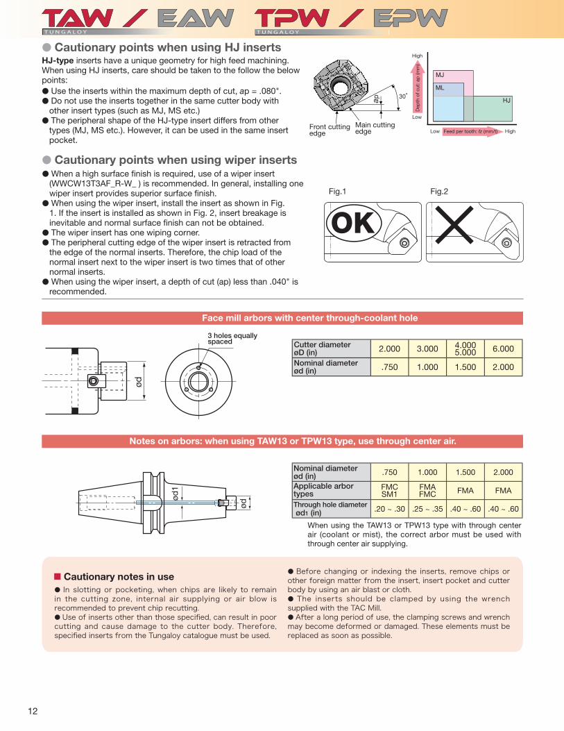
� Cautionary points when using wiper inserts� When a high surface fi nish is required, use of a wiper insert
(WWCW13T3AF_R-W_ ) is recommended. In general, installing one wiper insert provides superior surface fi nish.
� When using the wiper insert, install the insert as shown in Fig. 1. If the insert is installed as shown in Fig. 2, insert breakage is inevitable and normal surface fi nish can not be obtained.
� The wiper insert has one wiping corner.� The peripheral cutting edge of the wiper insert is retracted from
the edge of the normal inserts. Therefore, the chip load of the normal insert next to the wiper insert is two times that of other normal inserts.
� When using the wiper insert, a depth of cut (ap) less than .040" is recommended.
� Cautionary points when using HJ insertsHJ-type inserts have a unique geometry for high feed machining. When using HJ inserts, care should be taken to the follow the below points:� Use the inserts within the maximum depth of cut, ap = .080". � Do not use the inserts together in the same cutter body with
other insert types (such as MJ, MS etc.) � The peripheral shape of the HJ-type insert differs from other
types (MJ, MS etc.). However, it can be used in the same insert pocket.
Fig.1 Fig.2
Front cutting edge
Dep
th o
f cut
: ap
(mm
)
Main cutting edge Feed per tooth: fz (mm/t) HighLow
Low
High
Face mill arbors with center through-coolant hole
Cutter diameter øD (in)Nominal diameterød (in)
3 holes equallyspaced
Notes on arbors: when using TAW13 or TPW13 type, use through center air.
Nominal diameterød (in)Applicable arbor typesThrough hole diameter ød1 (in)
When using the TAW13 or TPW13 type with through center air (coolant or mist), the correct arbor must be used with through center air supplying.
■Cautionary notes in use� In slotting or pocketing, when chips are likely to remain in the cutting zone, internal air supplying or air blow is recommended to prevent chip recutting. � Use of inserts other than those specifi ed, can result in poor cutting and cause damage to the cutter body. Therefore, specifi ed inserts from the Tungaloy catalogue must be used.
� Before changing or indexing the inserts, remove chips or other foreign matter from the insert, insert pocket and cutter body by using an air blast or cloth.� The inserts should be clamped by using the wrench supplied with the TAC Mill.� After a long period of use, the clamping screws and wrench may become deformed or damaged. These elements must be replaced as soon as possible.

13
TPW13R300U0100A04 TPW13R300U0100A06SWMT1304PDPR-MS SWMT1304PDPR-MJ
AH140 AH140
400 330.007 .00414 10
.047 .110 x 5~ 2 3.150"
4"
2"
AISI 316
(ø 3.000", z = 4) (ø 3.000", z = 6)
TAW13R300U0100A06 TAW13R400U0150A07SWMT13T3AFPR-MJ SWMT13T3AFPR-HJ
AH120 T3130
600 790.006 .02426 126
.080 .080- ~ 3
(ø 3.000", z = 6) (ø 4.000", z = 7)
Cut
ting
co
nditi
ons
Part of workpiece Cutter InsertGrade
Workpiece material
Cutting speed: Vc (sfm) Feed rate: fz (ipt) Feed speed: Vf (ipm) Depth of cut: ap (in) Width of cut: ae (in) Method of machining Coolant Machine
Results
Face milling and shoulderingWet
Vertical machining center
Chromium molybdenum steel
85pieces
TPW13 (MJ)
120 pieces
In high impact heavy machining theTPW13 demonstrates stable tool life and reduced chipping.
C u t t i n g w i t h T P W 1 3 proved very silent with drast ica l l y improved surface fi nish.
passes
Conventional
Face millingDry
-
Hydraulic part Machine component
140% tool life
improvement!
150%Productivity
improvement!!
Cut
ting
co
nditi
ons
Practical examples
180%
tool lifeimprovement!
Part of workpiece Milling cutter
InsertGrade
Workpiece material
Cutting speed: Vc (sfm) Feed rate: fz (ipt) Feed speed: Vf (ipm) Depth of cut: ap (in) Width of cut: ae (in) Method of machining Coolant Machine
Results
Face millingDry
Vertical machining center BT50
Face millingWet
Vertical machining center BT50
Chromium molybdenum steel
100pieces
TAW13 (MJ) Compertitor
Still running!
Smooth cutting without chattering makes tool life stable.
270%Productivity
Improvement!!
Feed speed: Vf = 47 126 ipm.Even in high feed machining, the cutting is very smooth and silent.
Carbon steel (AISI 1055)
Machine component (structural part) Plate for die

Distributed by:
Feb. 2012 (TJ)
3726 N Ventura Drive, Arlington Heights, IL 60004, U.S.A.Inside Sales: +1-888-554-8394Technical Support: +1-888-554-8391 Fax: +1-888-554-8392
Tungaloy Canada432 Elgin St. Unit 3, Brantford, Ontario N3S 7P7, CanadaPhone: +1-519-758-5779 Fax: +1-519-758-5791
Tungaloy de Mexico S.A.C Los Arellano 113, Parque Industrial Siglo XXIAguascalientes, AGS, Mexico 20290Phone:+52-449-929-5410 Fax:+52-449-929-5411
www.tungaloyamerica.com
Become a fan on facebook
Follow us on Twitter @tungaloy
Watch our videos on You Tube
Scan for instant web access