taurus piping solutions flanges flanges · asme b16.48 – line blanks the standard covers a range...
TRANSCRIPT

38
FLANGES
Flanges
A flange is designed to connect sections of pipe or tube, or to join the pipe or tube to an assembly such as a pressure vessel, valve or pump. Flanges are joined by bolting, and sealing is completed with the use of gaskets and other sealing methods, and fixed to the piping system by welding or threading.
A comprehensive range of Table D and E flanges to AS 2129, and forged flanges to ASME standards in ratings of class, are stocked by Prochem throughout Australia in sizes DN 15 (NPS 1/2") though to DN 400 (NPS 16").
Larger sizes to DN 1500 (NPS 60") and ratings to Class 2500 are also available through our worldwide network of quality approved mills and stockists.
Standard stocks include 304L and 316L stainless steels, with many other materials available on request
including Cr-Mo, low temperature alloys, nickel based
alloys and duplex grades. All flanges can be supplied
complete with material certificates in strict accordance
with the applicable standards, under the control of
Prochem’s ISO 9001:2008 quality assurance program.
FLANGE FACINGS
The most common types of flange facings are:-
• Flat Face (commonly used on AS 2129 Flanges) and
• Raised Face (commonly used on ASME Flanges)
Other facings include:-
• Ring-Joint (RTJ)
• Tongue and Groove
• Male and Female (Spigot and Recess)
• O-Ring Groove (O-Ring Spigot and O-Ring Groove)
Taurus Piping Solutions
TAURUS PIPING SOLUTIONS
39
FLANGES
MANUFACTURING STANDARDS
In Australia, flanges are commonly manufactured to the following standards:
1. AS 2129 – Flanges for Pipes, Valves and Fittings
They are commonly known as “Table” flanges, (e.g. Table D) and are usually made from plate or forgings, hence the pipe bore and tube bore slip-on or blind are the most common forms.
The standard covers nominal sizes DN 15 (NPS 1/2") to DN 3000 (NPS 120") in Table D, and DN 1200 (NPS 48") in Table E, but flanges up to DN 400 (NPS 16") are normally available off the shelf, in 304(L) or 316(L) grades. The F and Table H flanges are also reasonably popular and a range is carried off the shelf. The other rating classes of Table A, J, K, R, S and T are less common usage than Table D or E.
2. AS 4087 – Metallic Flanges for Waterworks Purposes
Formerly included in AS 2129, this standard covers nominal sizes of DN 15 (NPS 1/2") to DN 1200 (NPS 48") in various materials and pressure ratings designated by their allowable operating pressure (AOP) – PN Rating – but the nominal size range is limited to DN 50 (NPS 2") to DN 1200 (NPS 48") with pressure ratings of PN 16, PN 21 and PN 35 for stainless steel grades of material. These flanges are generally stocked in sizes DN 50 (NPS 2") to DN 600 (NPS 24") with a PN 16 pressure rating. The other sizes and pressure ratings are available with a lead time.
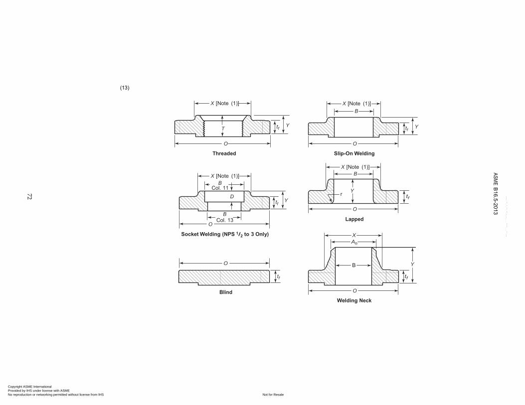
3. ASME B16.5 - Pipe Flanges and Fittings
These are commonly referred to by their pressure rating class, (e.g. ANSI 150 or 150lb). This standard specifies that for the standard 304(L) and 316(L) grades, the flanges must be forged, (except for blind flanges which can be made from plate).
The most commonly stocked flanges are slip-on, weld neck and blind. (Note that the slip-on flange has a hub similar to the lap joint flange and they should not be misinterpreted).
The standard covers sizes up to DN 15 (NPS 1/2") to DN 600 (NPS 24"), in Class ratings of 150, 300, 400, 600, 900, 1500 and 2500.
4. ASME B16.47 - Large Diameter Steel Flanges
This standard covers the size range of DN 650 (NPS 26") to DN 1500 (NPS 60"). In Series A, Class ratings of 150, 300, 400, 600 and 900 are covered. In Series B, Class ratings of 150, 300, 400, 600 and 900 are covered. These flanges are not commonly stocked, but are available on a lead time.
5. ASME B16.36 - Orifice Flanges
This standard covers DN 25 (NPS 1") to DN 600 (NPS 24") in Class ratings of 300, 400, 600, 900, 1500 and 2500. These flanges are not commonly stocked, but are available on a lead time.
6. ASME B16.48 – Line Blanks
The standard covers a range of line blanks in nominal sizes DN 15 (NPS 1/2") to DN 600 (NPS 24") for installation between ASME B16.5 flanges in Class ratings of 150, 300, 600, 900, 1500 and 2500 and replaces the API 590 Standard. The facing finishes are in accordance with ASME B16.5 and are listed as raised face, male ring-joint and female ring-joint.
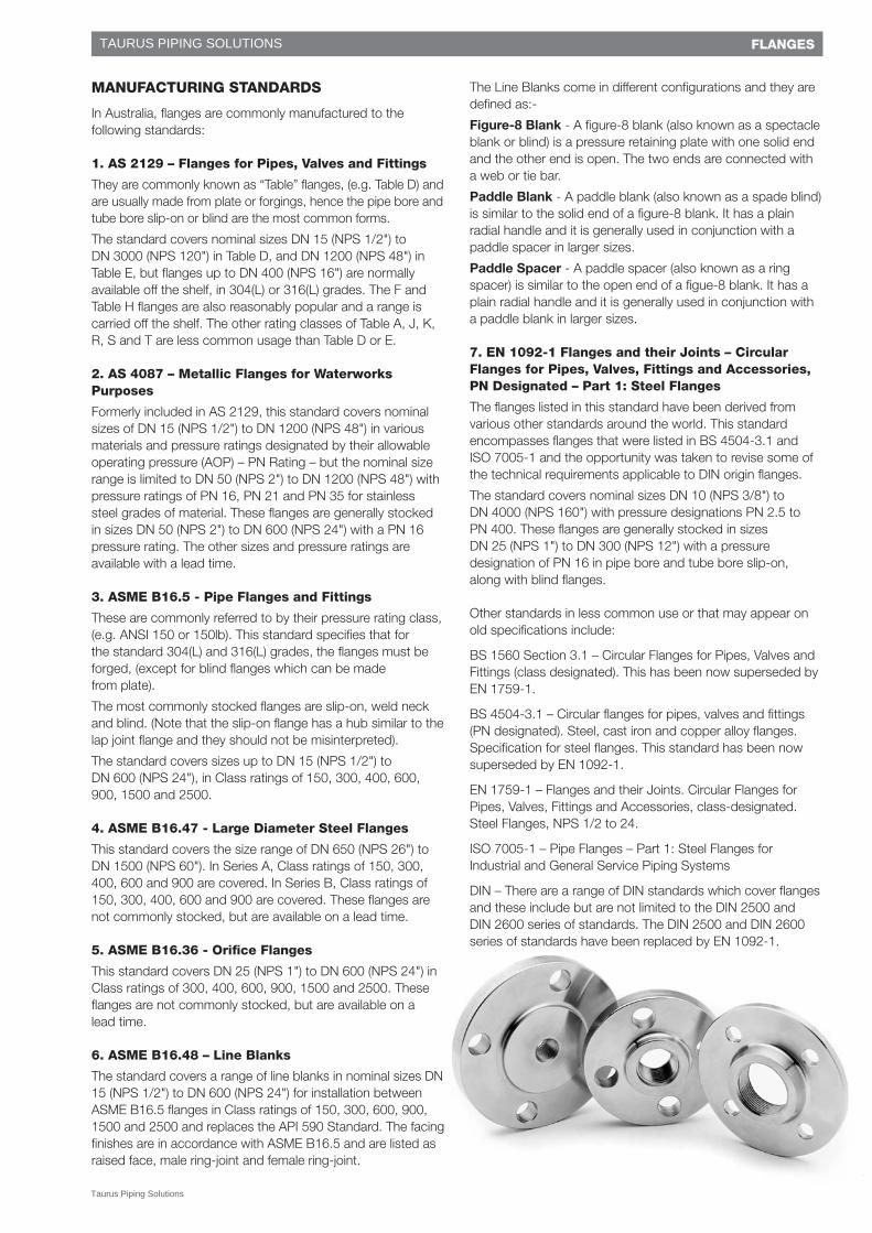
The Line Blanks come in different configurations and they are defined as:-
Figure-8 Blank - A figure-8 blank (also known as a spectacle blank or blind) is a pressure retaining plate with one solid end and the other end is open. The two ends are connected with a web or tie bar.
Paddle Blank - A paddle blank (also known as a spade blind) is similar to the solid end of a figure-8 blank. It has a plain radial handle and it is generally used in conjunction with a paddle spacer in larger sizes.
Paddle Spacer - A paddle spacer (also known as a ring spacer) is similar to the open end of a figue-8 blank. It has a plain radial handle and it is generally used in conjunction with a paddle blank in larger sizes.
7. EN 1092-1 Flanges and their Joints – Circular Flanges for Pipes, Valves, Fittings and Accessories, PN Designated – Part 1: Steel Flanges
The flanges listed in this standard have been derived from various other standards around the world. This standard encompasses flanges that were listed in BS 4504-3.1 and ISO 7005-1 and the opportunity was taken to revise some of the technical requirements applicable to DIN origin flanges.
The standard covers nominal sizes DN 10 (NPS 3/8") to DN 4000 (NPS 160") with pressure designations PN 2.5 to PN 400. These flanges are generally stocked in sizes DN 25 (NPS 1") to DN 300 (NPS 12") with a pressure designation of PN 16 in pipe bore and tube bore slip-on, along with blind flanges.
Other standards in less common use or that may appear on old specifications include:
BS 1560 Section 3.1 – Circular Flanges for Pipes, Valves and Fittings (class designated). This has been now superseded by EN 1759-1.
BS 4504-3.1 – Circular flanges for pipes, valves and fittings (PN designated). Steel, cast iron and copper alloy flanges. Specification for steel flanges. This standard has been now superseded by EN 1092-1.
EN 1759-1 – Flanges and their Joints. Circular Flanges for Pipes, Valves, Fittings and Accessories, class-designated. Steel Flanges, NPS 1/2 to 24.
ISO 7005-1 – Pipe Flanges – Part 1: Steel Flanges for Industrial and General Service Piping Systems
DIN – There are a range of DIN standards which cover flanges and these include but are not limited to the DIN 2500 and DIN 2600 series of standards. The DIN 2500 and DIN 2600 series of standards have been replaced by EN 1092-1.
Taurus Piping Solutions
TAURUS PIPING SOLUTIONS
40
FLANGES
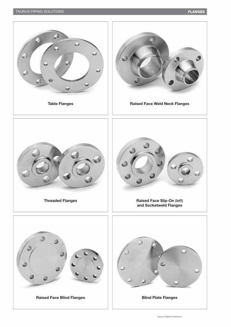
Threaded Flanges
Raised Face Blind Flanges
Table Flanges
Raised Face Slip-On (left)and Socketweld Flanges
Blind Plate Flanges
Raised Face Weld Neck Flanges
Taurus Piping Solutions
TAURUS PIPING SOLUTIONS
41
FLANGES
TYPES AND APPLICATIONS
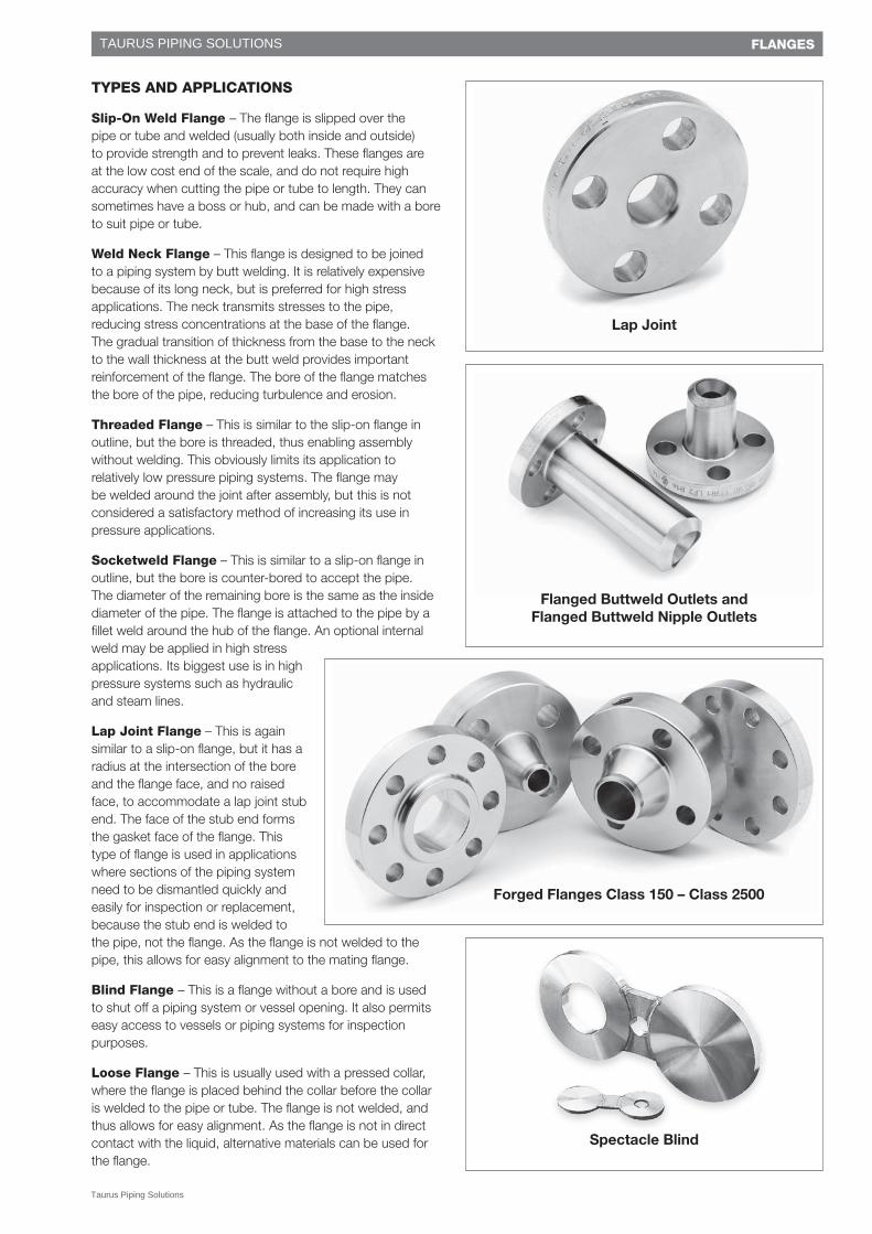
Slip-On Weld Flange – The flange is slipped over the pipe or tube and welded (usually both inside and outside) to provide strength and to prevent leaks. These flanges are at the low cost end of the scale, and do not require high accuracy when cutting the pipe or tube to length. They can sometimes have a boss or hub, and can be made with a bore to suit pipe or tube.
Weld Neck Flange – This flange is designed to be joined to a piping system by butt welding. It is relatively expensive because of its long neck, but is preferred for high stress applications. The neck transmits stresses to the pipe, reducing stress concentrations at the base of the flange. The gradual transition of thickness from the base to the neck to the wall thickness at the butt weld provides important reinforcement of the flange. The bore of the flange matches the bore of the pipe, reducing turbulence and erosion.
Threaded Flange – This is similar to the slip-on flange in outline, but the bore is threaded, thus enabling assembly without welding. This obviously limits its application to relatively low pressure piping systems. The flange may be welded around the joint after assembly, but this is not considered a satisfactory method of increasing its use in pressure applications.
Socketweld Flange – This is similar to a slip-on flange in outline, but the bore is counter-bored to accept the pipe. The diameter of the remaining bore is the same as the inside diameter of the pipe. The flange is attached to the pipe by a fillet weld around the hub of the flange. An optional internal weld may be applied in high stress applications. Its biggest use is in high pressure systems such as hydraulic and steam lines.
Lap Joint Flange – This is again similar to a slip-on flange, but it has a radius at the intersection of the bore and the flange face, and no raised face, to accommodate a lap joint stub end. The face of the stub end forms the gasket face of the flange. This type of flange is used in applications where sections of the piping system need to be dismantled quickly and easily for inspection or replacement, because the stub end is welded to the pipe, not the flange. As the flange is not welded to the pipe, this allows for easy alignment to the mating flange.
Blind Flange – This is a flange without a bore and is used to shut off a piping system or vessel opening. It also permits easy access to vessels or piping systems for inspection purposes.
Loose Flange – This is usually used with a pressed collar, where the flange is placed behind the collar before the collar is welded to the pipe or tube. The flange is not welded, and thus allows for easy alignment. As the flange is not in direct contact with the liquid, alternative materials can be used for the flange.
Forged Flanges Class 150 – Class 2500
Lap Joint
Spectacle Blind
Flanged Buttweld Outlets and Flanged Buttweld Nipple Outlets
Taurus Piping Solutions
TAURUS PIPING SOLUTIONS
ASME B
16.5-2013
72
(13)
X [Note (1)] X [Note (1)] B
T tf
Y tf Y
O
Threaded
O Slip-On Welding
X [Note (1)]
B Col. 11
D
B Col. 13
tf
Y
X [Note (1)] B
r Y
tf
O
Lapped O
Socket Welding (NPS 1/2 to 3 Only) X
Ah
O B Y
tf tf
Blind O Welding Neck
Copyright ASME International Provided by IHS under license with ASME
Not for ResaleNo reproduction or networking permitted without license from IHS
--`,,```,,,,````-`-`,,`,,`,`,,`---
�
�
�� �� �� �� �� �� �� �� �� ��� ��� ��� ��� ��� ���� � � � � +XE� � � � � � � � &RUQHU� �
'LDPHWHU� %RUH�%HJLQQLQJ� �� %RUH� 5DGLXV�
� � � � � � � � � � � � � � �� 2XWVLGH� 0LQLPXP� � � &KDPIHU� 7KUHDGHG��� � 7KUHDG� 0LQLPXP� � 1HFN�� /DSSHG� �1RPLQDO� 'LDPHWHU� 7KLFNQHVV� 0LQLPXP� � :HOGLQJ� 6OLS�RQ�� � � /HQJWK� 6OLS�RQ�� � 6RFNHW� )ODQJH� �3LSH� RI� RI�)ODQJH�� 7KLFNQHVV� 'LDPHWHU� 1HFN�� 6RFNHW� � :HOGLQJ� 7KUHDGHG�� 6RFNHW� 0LQLPXP� :HOGLQJ�� DQG� 'HSWK�RI�6L]H�� )ODQJH�� WI� /DS�-RLQW�� RI�+XE�� $K� :HOGLQJ�� /DSSHG�� 1HFN�� 7� :HOGLQJ�� /DSSHG�� %� 3LSH�� 6RFNHW��136� 2� >1RWHV��������@� WI� ;� >1RWH����@� <� <� <� >1RWH����@� %� %� >1RWH����@� U� '�
� ������
���
����
����� �� ����
$60(�%
����������
73
��������
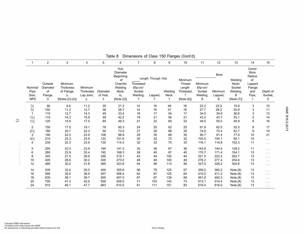
7DEOH��� 'LPHQVLRQV�RI�&ODVV�����)ODQJHV��&RQW¶G�������
RI� �� /HQJWK� 7KURXJK� +XE� �0LQLPXP� :HOGLQJ� RI�
������
�»�� ��� �����»�� ���� �����
������
����
������
���� ��� ��� ��� ����� �������� ��� ��� ��� ����� ���������� ��� �����
�� ���� ����� ����� ��� ����� ��� ��� ��� ��� ����� ����� ����� �� �����»�� ���� ����� ����� ��� ����� ��� ��� ��� ��� ����� ����� ����� �� �����»�� ���� ����� ����� ��� ����� ��� ��� ��� ��� ����� ����� ����� �� ����� ���� ����� ����� ��� ����� ��� ��� ��� ��� ����� ����� ����� �� �����»�� ���� ����� ����� ��� ����� ��� ��� ��� ��� ����� ����� ����� �� ����� ���� ����� ����� ���� ����� ��� ��� ��� ��� ����� ����� ����� ��� �����»�� ���� ����� ����� ���� ������ ��� ��� ��� ��� ������ ������ ����� ��� �������� ���� ����� ����� ���� ������ ��� ��� ��� ��� ������ ������ ������ ��� �������� ���� ����� ����� ���� ������ ��� ��� ��� ��� ������ ������ ������ ��� �������� ���� ����� ����� ���� ������ ��� ��� ��� ��� ������ ������ ������ ��� �������� ���� ����� ����� ���� ������ ��� ��� ���� ��� ������ ������ ������ ��� ��������� ���� ����� ����� ���� ������ ��� ��� ���� ��� ������ ������ ������ ��� ��������� ���� ����� ����� ���� ������ ��� ��� ���� ��� ������ ������ ������ ��� ��������� ���� ����� ����� ���� ������ ��� ��� ���� ��� ������ ������ 1RWH����� ��� ��������� ���� ����� ����� ���� ������ ��� ��� ���� ��� ������ ������ 1RWH����� ��� ��������� ���� ����� ����� ���� ������ ��� ��� ���� ��� ������ ������ 1RWH����� ��� ��������� ���� ����� ����� ���� ������ ��� ���� ���� ��� ������ ������ 1RWH����� ��� ��������� ���� ����� ����� ���� ������ ��� ���� ���� ��� ������ ������ 1RWH����� ��� ������
Copyright ASME International Provided by IHS under license with ASME
Not for ResaleNo reproduction or networking permitted without license from IHS
--`,,```,,,,````-`-`,,`,,`,`,,`---

ASME B16.5-2013
71
1 2 3 4 5 6 7 8 9 Length of Bolts, L [Note (4)]
Outside Drilling [Notes (2), (3)] Stud Bolts Machine
Pipe of of Bolt of Bolt Number Diameter 2-mm 2-mm Size, Flange, Circle, Holes, of of Bolts, Raised Ring Raised NPS O W in. Bolts in. Face Joint Face
1 110 79.4 11⁄4 115 88.9 11⁄2 125 98.4 2 150 120.7
21⁄2 180 139.7 3 190 152.4
31⁄2 215 177.8 4 230 190.5 5 255 215.9 6 280 241.3 8 345 298.5 10 405 362.0 12 485 431.8
Table 7 Templates for Drilling Class 150 Pipe Flanges and Flanged Fittings L
(13)
O
W Machine Bolt With Nuts
L
Flange
Point height [Note (1)]
Stud Bolt With Nuts
Nominal Diameter Diameter Diameter [Note (1)] Bolts
1⁄2 90 60.3 5⁄8 4 1⁄2 3⁄4 100 69.9 5⁄8 4 1⁄2
5⁄8 4 1⁄2 5⁄8 4 1⁄2 5⁄8 4 1⁄2
3⁄4 4 5⁄8 3⁄4 4 5⁄8 3⁄4 4 5⁄8 3⁄4 8 5⁄8 3⁄4 8 5⁄8
7⁄8 8 3⁄4 7⁄8 8 3⁄4 7⁄8 8 3⁄4
1 12 7⁄8
1 12 7⁄8
55
. . .
50
65 . . . 50 65 75 55 70 85 55 70 85 65 85 95 70 90 100 75 90 100 75 90 100 75 90 100 75 95 110 85
100 115 85 110 120 90 115 125 100 120 135 100
14 535 476.3 11⁄8 12 1 135 145 115 16 595 539.8 11⁄8 16 1 135 145 115 18 635 577.9 11⁄4 16 11⁄8 145 160 125 20 700 635.0 11⁄4 20 11⁄8 160 170 140 24 815 749.3 13⁄8 20 11⁄4 170 185 150
GENERAL NOTES: (a) Dimensions of Table 7 are in millimeters, except for diameters of bolts and bolt holes, which are in inch units. For dimensions in inch
units, refer to Mandatory Appendix II, Table II-7. (b) For other dimensions, see Tables 8 and 9. NOTES: (1) The length of the stud bolt does not include the height of the points (see para. 6.10.2). (2) For flange bolt holes, see para. 6.5. (3) For spot facing, see para. 6.6. (4) Bolt lengths not shown in the table may be determined in accordance with Nonmandatory Appendix C (see para. 6.10.2).
Copyright ASME International Provided by IHS under license with ASME
Not for ResaleNo reproduction or networking permitted without license from IHS
--`,,```,,,,````-`-`,,`,,`,`,,`---
ASME B
16.5-2013
82
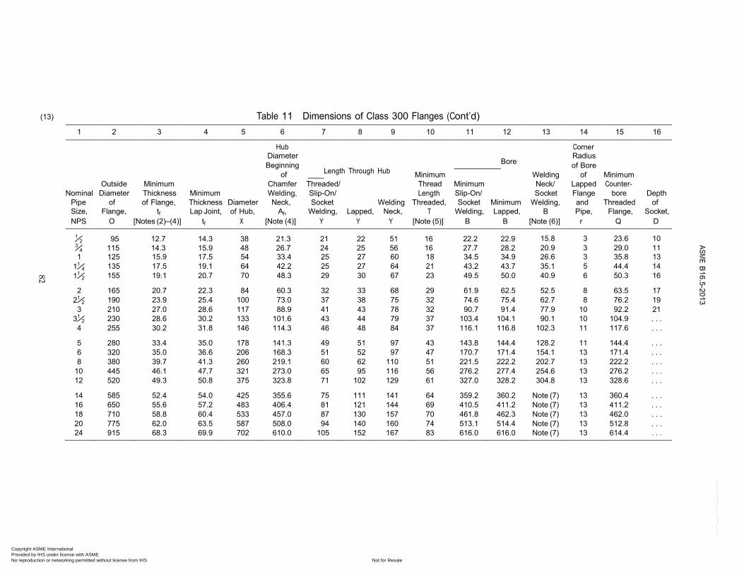
(13) Table 11 Dimensions of Class 300 Flanges (Cont’d)
1 2 3 4 5 6 7 8 9 10 11 12 13 14 15 16 Hub Corner
Diameter Radius Beginning Bore of Bore
of Length Through Hub Minimum Welding of Minimum Outside Minimum Chamfer Threaded/ Thread Minimum Neck/ Lapped Counter-
Nominal Diameter Thickness Minimum Welding, Slip-On/ Length Slip-On/ Socket Flange bore Depth Pipe of of Flange, Thickness Diameter Neck, Socket Welding Threaded, Socket Minimum Welding, and Threaded of Size, Flange, tf Lap Joint, of Hub, Ah Welding, Lapped, Neck, T Welding, Lapped, B Pipe, Flange, Socket, NPS O [Notes (2)–(4)] tf X [Note (4)] Y Y Y [Note (5)] B B [Note (6)] r Q D
1⁄2 95 12.7 14.3 38 21.3 21 22 51 16 22.2 22.9 3⁄4 115 14.3 15.9 48 26.7 24 25 56 16 27.7 28.2
15.8
3
23.6
10 20.9 3 29.0 11
1 125 15.9 17.5 54 33.4 25 27 60 18 34.5 34.9 26.6 3 35.8 13 11⁄4 135 17.5 19.1 64 42.2 25 27 64 21 43.2 43.7 35.1 5 44.4 14 11⁄2 155 19.1 20.7 70 48.3 29 30 67 23 49.5 50.0 40.9 6 50.3 16 2 165 20.7 22.3 84 60.3 32 33 68 29 61.9 62.5 52.5 8 63.5 17
21⁄2 190 23.9 25.4 100 73.0 37 38 75 32 74.6 75.4 62.7 8 76.2 19 3 210 27.0 28.6 117 88.9 41 43 78 32 90.7 91.4 77.9 10 92.2 21
31⁄2 230 28.6 30.2 133 101.6 43 44 79 37 103.4 104.1 90.1 10 104.9 . . . 4 255 30.2 31.8 146 114.3 46 48 84 37 116.1 116.8 102.3 11 117.6 . . . 5 280 33.4 35.0 178 141.3 49 51 97 43 143.8 144.4 128.2 11 144.4 . . . 6 320 35.0 36.6 206 168.3 51 52 97 47 170.7 171.4 154.1 13 171.4 . . . 8 380 39.7 41.3 260 219.1 60 62 110 51 221.5 222.2 202.7 13 222.2 . . .
10 445 46.1 47.7 321 273.0 65 95 116 56 276.2 277.4 254.6 13 276.2 . . . 12 520 49.3 50.8 375 323.8 71 102 129 61 327.0 328.2 304.8 13 328.6 . . . 14 585 52.4 54.0 425 355.6 75 111 141 64 359.2 360.2 Note (7) 13 360.4 . . . 16 650 55.6 57.2 483 406.4 81 121 144 69 410.5 411.2 Note (7) 13 411.2 . . . 18 710 58.8 60.4 533 457.0 87 130 157 70 461.8 462.3 Note (7) 13 462.0 . . . 20 775 62.0 63.5 587 508.0 94 140 160 74 513.1 514.4 Note (7) 13 512.8 . . . 24 915 68.3 69.9 702 610.0 105 152 167 83 616.0 616.0 Note (7) 13 614.4 . . .
Copyright ASME International Provided by IHS under license with ASME
Not for ResaleNo reproduction or networking permitted without license from IHS
--`,,```,,,,````-`-`,,`,,`,`,,`---
Outside
Nominal Diameter Diameter Diameter Pipe of of Bolt of Bolt Number Diameter Size, Flange, Circle, Holes, of of Bolts, NPS O W in. Bolts in.
ASME B16.5-2013
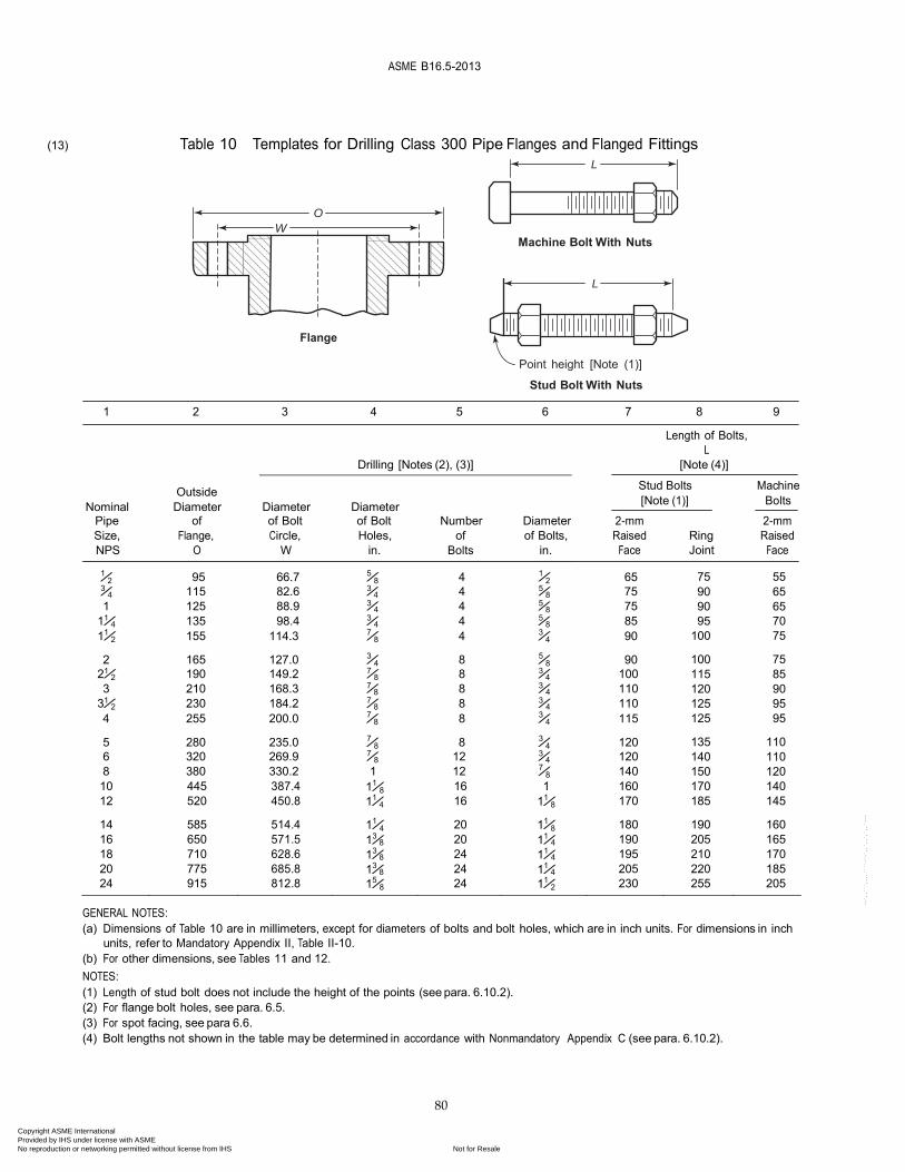
(13) Table 10 Templates for Drilling Class 300 Pipe Flanges and Flanged Fittings L
O
W Machine Bolt With Nuts
L
Flange
Point height [Note (1)]
Stud Bolt With Nuts
1 2 3 4 5 6 7 8 9
Length of Bolts, L
Drilling [Notes (2), (3)] [Note (4)]
Stud Bolts Machine [Note (1)] Bolts
2-mm Raised
Face
1⁄2 95 66.7 5⁄8 4 1⁄2 65 3⁄4 115 82.6 3⁄4 4 5⁄8 75 1 125 88.9 3⁄4 4 5⁄8 75
11⁄4 135 98.4 3⁄4 4 5⁄8 85 11⁄2 155 114.3 7⁄8 4 3⁄4 90
2 165 127.0 3⁄4 8 5⁄8 90 21⁄2 190 149.2 7⁄8 8 3⁄4 100 3 210 168.3 7⁄8 8 3⁄4 110
31⁄2 230 184.2 7⁄8 8 3⁄4 110 4 255 200.0 7⁄8 8 3⁄4 115
5 280 235.0 7⁄8 8 3⁄4 120 6 320 269.9 7⁄8 12 3⁄4 120 8 380 330.2 1 12 7⁄8 140
Ring Joint
2-mm Raised
Face 75 55 90 65 90 65 95 70
100 75 100 75 115 85 120 90 125 95 125 95 135 110 140 110 150 120
10 445 387.4 11⁄8 16 1 160 170 140 12 520 450.8 11⁄4 16 11⁄8 170 185 145 14 585 514.4 11⁄4 20 11⁄8 180 190 160 16 650 571.5 13⁄8 20 11⁄4 190 205 165 18 710 628.6 13⁄8 24 11⁄4 195 210 170 20 775 685.8 13⁄8 24 11⁄4 205 220 185 24 915 812.8 15⁄8 24 11⁄2 230 255 205
GENERAL NOTES: (a) Dimensions of Table 10 are in millimeters, except for diameters of bolts and bolt holes, which are in inch units. For dimensions in inch
units, refer to Mandatory Appendix II, Table II-10. (b) For other dimensions, see Tables 11 and 12. NOTES: (1) Length of stud bolt does not include the height of the points (see para. 6.10.2). (2) For flange bolt holes, see para. 6.5. (3) For spot facing, see para 6.6. (4) Bolt lengths not shown in the table may be determined in accordance with Nonmandatory Appendix C (see para. 6.10.2).
80
Copyright ASME International Provided by IHS under license with ASME
Not for ResaleNo reproduction or networking permitted without license from IHS
--`,,```,,,,````-`-`,,`,,`,`,,`---
ASME B16.5-2013
89
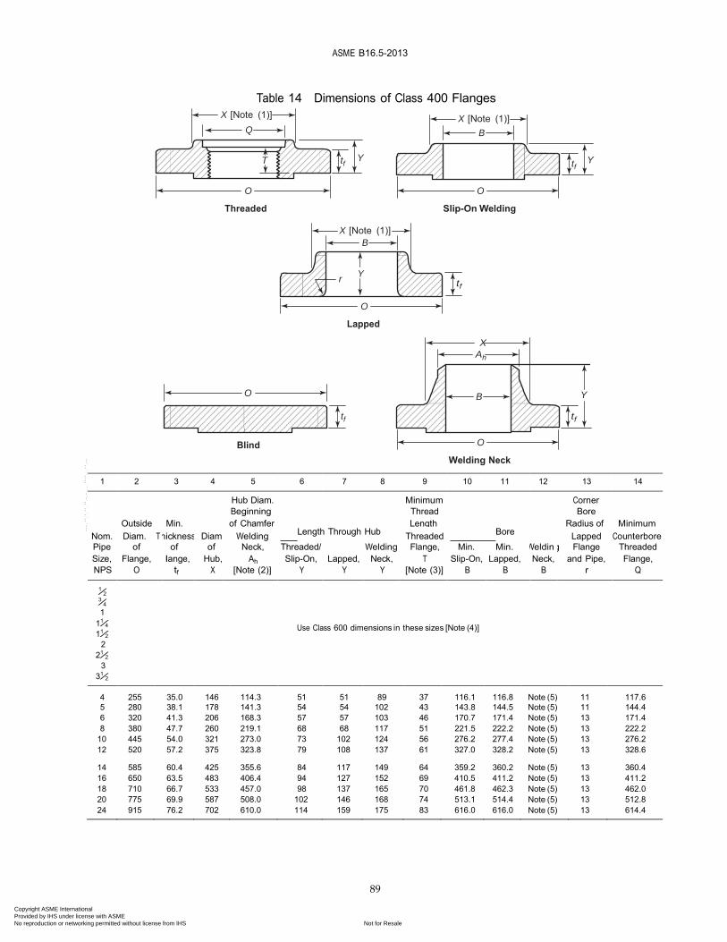
Table 14 Dimensions of Class 400 Flanges X [Note (1)]
Q
X [Note (1)]
B
T tf Y tf
Y
O
Threaded
O Slip-On Welding
X [Note (1)]
B
Y
r tf
O
Lapped
X
Ah
O B Y
tf tf
Blind O Welding Neck
1 2 3 4 5 6 7 8 9 10 11 12 13 14 Hub Diam. Minimum Corner Beginning Thread Bore
Outside Min. of Chamfer Length Radius of Minimum Nom. Diam. T hickness Diam. Welding Length Through Hub Threaded Bore Lapped Counterbore Pipe of of of Neck, Threaded/ Welding Flange, Min. Min. Weldin g Flange Threaded Size, Flange, F lange, Hub, Ah Slip-On, Lapped, Neck, T Slip-On, Lapped, Neck, and Pipe, Flange, NPS O tf X [Note (2)] Y Y Y [Note (3)] B B B r Q
1⁄2 3⁄4 1 11⁄4
11⁄2
2 21⁄2
3 31⁄2
Use Class 600 dimensions in these sizes [Note (4)]
4
255 35.0
146 114.3
51 51
89 37
116.1 116.8
Note (5) 11
117.6 5 280 38.1 178 141.3 54 54 102 43 143.8 144.5 Note (5) 11 144.4 6 320 41.3 206 168.3 57 57 103 46 170.7 171.4 Note (5) 13 171.4 8 380 47.7 260 219.1 68 68 117 51 221.5 222.2 Note (5) 13 222.2
10 445 54.0 321 273.0 73 102 124 56 276.2 277.4 Note (5) 13 276.2 12 520 57.2 375 323.8 79 108 137 61 327.0 328.2 Note (5) 13 328.6 14 585 60.4 425 355.6 84 117 149 64 359.2 360.2 Note (5) 13 360.4 16 650 63.5 483 406.4 94 127 152 69 410.5 411.2 Note (5) 13 411.2 18 710 66.7 533 457.0 98 137 165 70 461.8 462.3 Note (5) 13 462.0 20 775 69.9 587 508.0 102 146 168 74 513.1 514.4 Note (5) 13 512.8 24 915 76.2 702 610.0 114 159 175 83 616.0 616.0 Note (5) 13 614.4
Copyright ASME International Provided by IHS under license with ASME
Not for ResaleNo reproduction or networking permitted without license from IHS
--`,,```,,,,````-`-`,,`,,`,`,,`---
ASME B16.5-2013
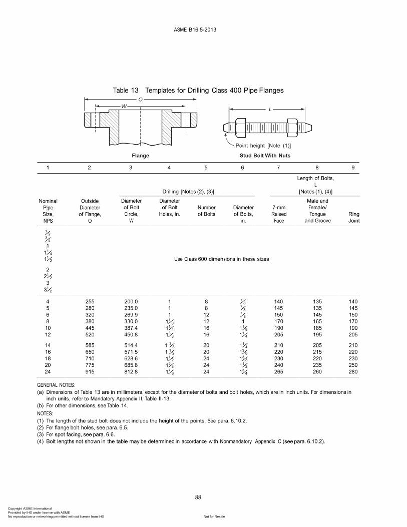
88
8 380 330.0 11⁄8 12 1 170 165 170 10 445 387.4 11⁄4 16 11⁄8 190 185 190 12 520 450.8 13⁄8 16 11⁄4 205 195 205 14 585 514.4 1 3⁄8 20 11⁄4 210 205 210 16 650 571.5 1 1⁄2 20 13⁄8 220 215 220 18 710 628.6 11⁄2 24 13⁄8 230 220 230 20 775 685.8 15⁄8 24 11⁄2 240 235 250 24 915 812.8 17⁄8 24 13⁄4 265 260 280
Table 13 Templates for Drilling Class 400 Pipe Flanges O
L
Point height [Note (1)]
Flange Stud Bolt With Nuts
1 2 3 4 5 6 7 8 9
Length of Bolts, L
Drilling [Notes (2), (3)] [Notes (1), (4)]
Nominal Pipe Size, NPS
Outside Diameter of Flange,
O
Diameter of Bolt Circle,
W
Diameter of Bolt
Holes, in.
Number of Bolts
Diameter of Bolts,
in.
7-mm Raised
Face
Male and Female/ Tongue
and Groove
Ring Joint
1⁄2 3⁄4
1 11⁄4
11⁄2
Use Cl ass 600 dimen
sions in these
sizes
2 21⁄2 3
31⁄2
4
255
200.0
1
8 7⁄8
140
135
140 5 280 235.0 1 8 7⁄8 145 135 145 6 320 269.9 1 12 7⁄8 150 145 150
GENERAL NOTES: (a) Dimensions of Table 13 are in millimeters, except for the diameter of bolts and bolt holes, which are in inch units. For dimensions in
inch units, refer to Mandatory Appendix II, Table II-13. (b) For other dimensions, see Table 14. NOTES: (1) The length of the stud bolt does not include the height of the points. See para. 6.10.2. (2) For flange bolt holes, see para. 6.5. (3) For spot facing, see para. 6.6. (4) Bolt lengths not shown in the table may be determined in accordance with Nonmandatory Appendix C (see para. 6.10.2).
Copyright ASME International Provided by IHS under license with ASME
Not for ResaleNo reproduction or networking permitted without license from IHS
--`,,```,,,,````-`-`,,`,,`,`,,`---
ASME B
16.5-2013
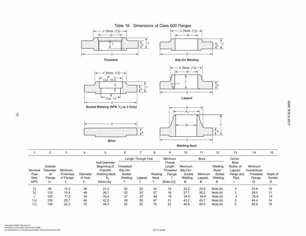
92
Table 16 Dimensions of Class 600 Flanges X [Note (1)]
Q
T
tf
Y
X [Note (1)] B
tf
Y
O
Threaded
O Slip-On Welding
X [Note (1)]
B Col. 10
D
B Col. 12
O Socket Welding (NPS 1/2 to 3 Only)
O
tf
Y
tf
X [Note (1)] B
r
Y tf
O
Lapped
X
Ah
B Y
tf
Blind O
Welding Neck
1 2 3 4 5 6 7 8 9 10 11 12 13 14 15
Length Through Hub Minimum Bore Corner
Hub Diameter Thread Bore Outside Beginning of Threaded/ Length Minimum Welding Radius of Minimum
Nominal Diameter Minimum Chamfer Slip-On/ Threaded Slip-On/ Neck/ Lapped Counterbore Pipe of Thickness Diameter Welding Neck, Socket Welding Flange, Socket Minimum Socket Flange and Threaded Depth of Size, Flange, of Flange, of Hub, Ah Welding, Lapped, Neck, T Welding, Lapped, Welding, Pipe, Flange, Socket, NPS O tf X [Note (2)] Y Y Y [Note (3)] B B B r Q D
1⁄2 95 14.3 38 21.3 22 22 52 16 22.2 22.9 Note (4) 3 23.6 10 3⁄4 115 15.9 48 26.7 25 25 57 16 27.7 28.2 Note (4) 3 29.0 11 1 125 17.5 54 33.4 27 27 62 18 34.5 34.9 Note (4) 3 35.8 13
11⁄4 135 20.7 64 42.2 29 29 67 21 43.2 43.7 Note (4) 5 44.4 14 11⁄2 155 22.3 70 48.3 32 32 70 23 49.5 50.0 Note (4) 6 50.6 16
Copyright ASME International Provided by IHS under license with ASME
Not for ResaleNo reproduction or networking permitted without license from IHS
--`,,```,,,,````-`-`,,`,,`,`,,`---
ASME B
16.5-2013
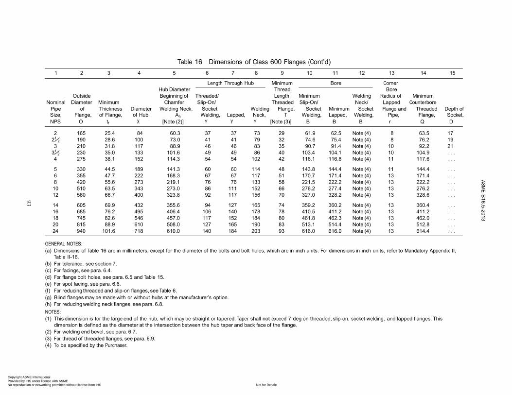
93
Table 16 Dimensions of Class 600 Flanges (Cont’d)
1 2 3 4 5 6 7 8 9 10 11 12 13 14 15
Length Through Hub Minimum Bore Corner Hub Diameter Thread Bore
Outside Beginning of Threaded/ Length Minimum Welding Radius of Minimum Nominal Diameter Minimum Chamfer Slip-On/ Threaded Slip-On/ Neck/ Lapped Counterbore
Pipe of Thickness Diameter Welding Neck, Socket Welding Flange, Socket Minimum Socket Flange and Threaded Depth of Size, Flange, of Flange, of Hub, Ah Welding, Lapped, Neck, T Welding, Lapped, Welding, Pipe, Flange, Socket, NPS O tf X [Note (2)] Y Y Y [Note (3)] B B B r Q D
2 165 25.4 84 60.3 37 37 73 29 61.9 62.5 Note (4) 8 63.5 17
21⁄2 190 28.6 100 73.0 41 41 79 32 74.6 75.4 Note (4) 8 76.2 19 3 210 31.8 117 88.9 46 46 83 35 90.7 91.4 Note (4) 10 92.2 21
31⁄2 230 35.0 133 101.6 49 49 86 40 103.4 104.1 Note (4) 10 104.9 . . . 4 275 38.1 152 114.3 54 54 102 42 116.1 116.8 Note (4) 11 117.6 . . .
5 330 44.5 189 141.3 60 60 114 48 143.8 144.4 Note (4) 11 144.4 . . . 6 355 47.7 222 168.3 67 67 117 51 170.7 171.4 Note (4) 13 171.4 . . . 8 420 55.6 273 219.1 76 76 133 58 221.5 222.2 Note (4) 13 222.2 . . . 10 510 63.5 343 273.0 86 111 152 66 276.2 277.4 Note (4) 13 276.2 . . . 12 560 66.7 400 323.8 92 117 156 70 327.0 328.2 Note (4) 13 328.6 . . .
14 605 69.9 432 355.6 94 127 165 74 359.2 360.2 Note (4) 13 360.4 . . . 16 685 76.2 495 406.4 106 140 178 78 410.5 411.2 Note (4) 13 411.2 . . . 18 745 82.6 546 457.0 117 152 184 80 461.8 462.3 Note (4) 13 462.0 . . . 20 815 88.9 610 508.0 127 165 190 83 513.1 514.4 Note (4) 13 512.8 . . . 24 940 101.6 718 610.0 140 184 203 93 616.0 616.0 Note (4) 13 614.4 . . .
GENERAL NOTES: (a) Dimensions of Table 16 are in millimeters, except for the diameter of the bolts and bolt holes, which are in inch units. For dimensions in inch units, refer to Mandatory Appendix II,
Table II-16. (b) For tolerance, see section 7. (c) For facings, see para. 6.4. (d) For flange bolt holes, see para. 6.5 and Table 15. (e) For spot facing, see para. 6.6. (f) For reducing threaded and slip-on flanges, see Table 6. (g) Blind flanges may be made with or without hubs at the manufacturer’s option. (h) For reducing welding neck flanges, see para. 6.8. NOTES: (1) This dimension is for the large end of the hub, which may be straight or tapered. Taper shall not exceed 7 deg on threaded, slip-on, socket-welding, and lapped flanges. This
dimension is defined as the diameter at the intersection between the hub taper and back face of the flange. (2) For welding end bevel, see para. 6.7. (3) For thread of threaded flanges, see para. 6.9. (4) To be specified by the Purchaser.
Copyright ASME International Provided by IHS under license with ASME
Not for ResaleNo reproduction or networking permitted without license from IHS
--`,,```,,,,````-`-`,,`,,`,`,,`---
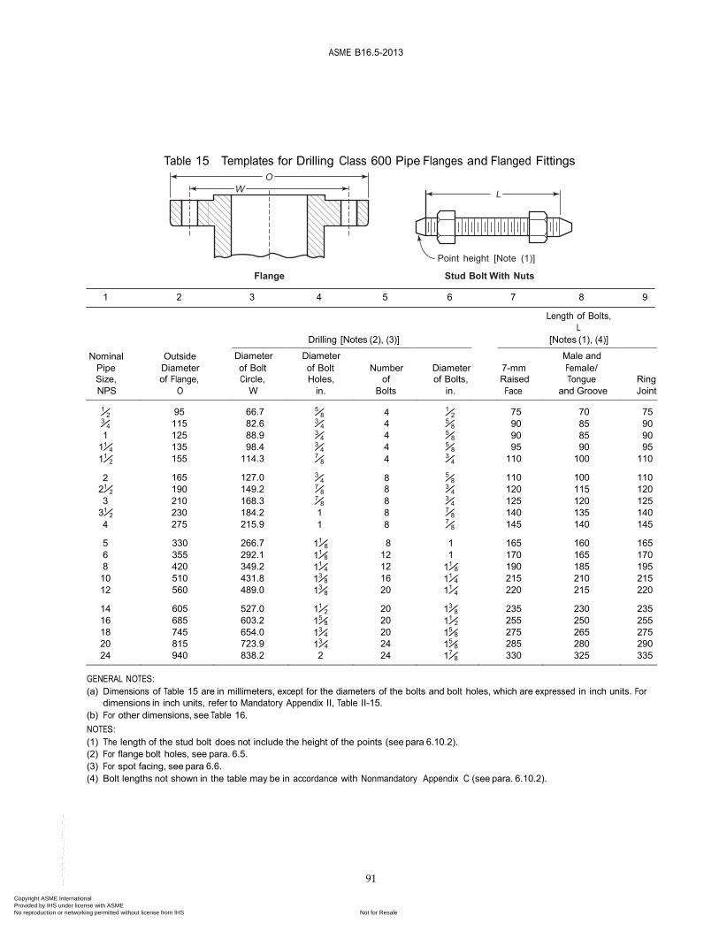
ASME B16.5-2013
91
Nominal Outside Diameter Diameter Male and Pipe Diameter of Bolt of Bolt Number Diameter 7-mm Female/ Size, of Flange, Circle, Holes, of of Bolts, Raised Tongue Ring NPS O W in. Bolts in. Face and Groove Joint
95
66.7
115 82.6 125 88.9 135 98.4 155 114.3 165 127.0 190 149.2 210 168.3 230 184.2 275 215.9
Table 15 Templates for Drilling Class 600 Pipe Flanges and Flanged Fittings O
L
Point height [Note (1)]
Flange Stud Bolt With Nuts
1 2 3 4 5 6 7 8 9
Length of Bolts, L
Drilling [Notes (2), (3)] [Notes (1), (4)]
1⁄2
5⁄8 4 1⁄2 3⁄4
3⁄4 4 5⁄8
1 3⁄4 4 5⁄8
11⁄4 3⁄4 4 5⁄8
11⁄2 7⁄8 4 3⁄4
2 3⁄4 8 5⁄8
21⁄2 7⁄8 8 3⁄4
3 7⁄8 8 3⁄4
31⁄2 1 8 7⁄8
4 1 8 7⁄8
75
70
75
90 85 90 90 85 90 95 90 95
110 100 110 110 100 110 120 115 120 125 120 125 140 135 140 145 140 145
5 330 266.7 11⁄8 8 1 165 160 165 6 355 292.1 11⁄8 12 1 170 165 170 8 420 349.2 11⁄4 12 11⁄8 190 185 195 10 510 431.8 13⁄8 16 11⁄4 215 210 215 12 560 489.0 13⁄8 20 11⁄4 220 215 220 14 605 527.0 11⁄2 20 13⁄8 235 230 235 16 685 603.2 15⁄8 20 11⁄2 255 250 255 18 745 654.0 13⁄4 20 15⁄8 275 265 275 20 815 723.9 13⁄4 24 15⁄8 285 280 290 24 940 838.2 2 24 17⁄8 330 325 335
GENERAL NOTES: (a) Dimensions of Table 15 are in millimeters, except for the diameters of the bolts and bolt holes, which are expressed in inch units. For
dimensions in inch units, refer to Mandatory Appendix II, Table II-15. (b) For other dimensions, see Table 16. NOTES: (1) The length of the stud bolt does not include the height of the points (see para 6.10.2). (2) For flange bolt holes, see para. 6.5. (3) For spot facing, see para 6.6. (4) Bolt lengths not shown in the table may be in accordance with Nonmandatory Appendix C (see para. 6.10.2).
Copyright ASME International Provided by IHS under license with ASME
Not for ResaleNo reproduction or networking permitted without license from IHS
--`,,```,,,,````-`-`,,`,,`,`,,`---
ASME B16.5-2013
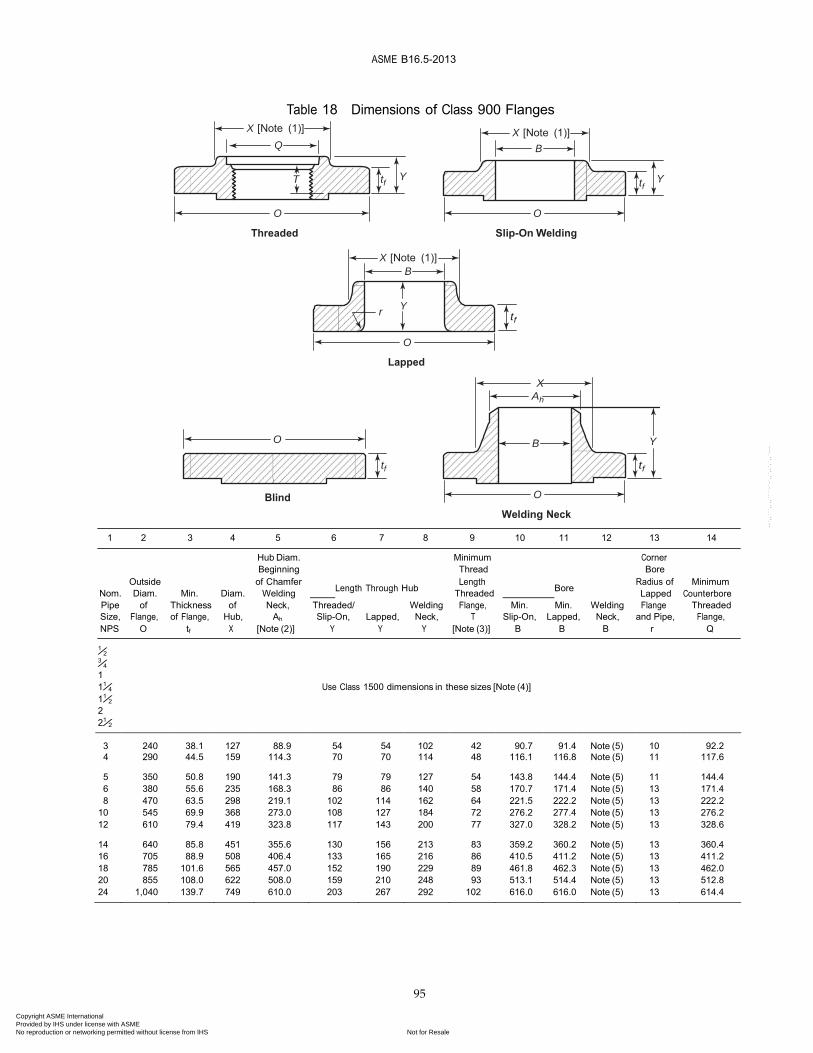
95
Table 18 Dimensions of Class 900 Flanges X [Note (1)]
Q
X [Note (1)]
B
T tf Y tf
Y
O
Threaded
O Slip-On Welding
X [Note (1)]
B
Y
r tf
O
Lapped
X
Ah
O B Y
tf tf
Blind O Welding Neck
1 2 3 4 5 6 7 8 9 10 11 12 13 14
Hub Diam. Minimum Corner Beginning Thread Bore
Outside of Chamfer Length Radius of Minimum Nom. Diam. Min. Diam. Welding Length Through Hub Threaded Bore Lapped Counterbore Pipe of Thickness of Neck, Threaded/ Welding Flange, Min. Min. Welding Flange Threaded Size, Flange, of Flange, Hub, Ah Slip-On, Lapped, Neck, T Slip-On, Lapped, Neck, and Pipe, Flange, NPS O tf X [Note (2)] Y Y Y [Note (3)] B B B r Q
1⁄2
3⁄4
1 11⁄4 Use Class 1500 dimensions in these sizes [Note (4)] 11⁄2
2 21⁄2
3
240 38.1
127 88.9
54 54
102 42
90.7 91.4
Note (5) 10
92.2 4 290 44.5 159 114.3 70 70 114 48 116.1 116.8 Note (5) 11 117.6 5 350 50.8 190 141.3 79 79 127 54 143.8 144.4 Note (5) 11 144.4 6 380 55.6 235 168.3 86 86 140 58 170.7 171.4 Note (5) 13 171.4 8 470 63.5 298 219.1 102 114 162 64 221.5 222.2 Note (5) 13 222.2
10 545 69.9 368 273.0 108 127 184 72 276.2 277.4 Note (5) 13 276.2 12 610 79.4 419 323.8 117 143 200 77 327.0 328.2 Note (5) 13 328.6 14 640 85.8 451 355.6 130 156 213 83 359.2 360.2 Note (5) 13 360.4 16 705 88.9 508 406.4 133 165 216 86 410.5 411.2 Note (5) 13 411.2 18 785 101.6 565 457.0 152 190 229 89 461.8 462.3 Note (5) 13 462.0 20 855 108.0 622 508.0 159 210 248 93 513.1 514.4 Note (5) 13 512.8 24 1,040 139.7 749 610.0 203 267 292 102 616.0 616.0 Note (5) 13 614.4
Copyright ASME International Provided by IHS under license with ASME
Not for ResaleNo reproduction or networking permitted without license from IHS
--`,,```,,,,````-`-`,,`,,`,`,,`---
ASME B16.5-2013
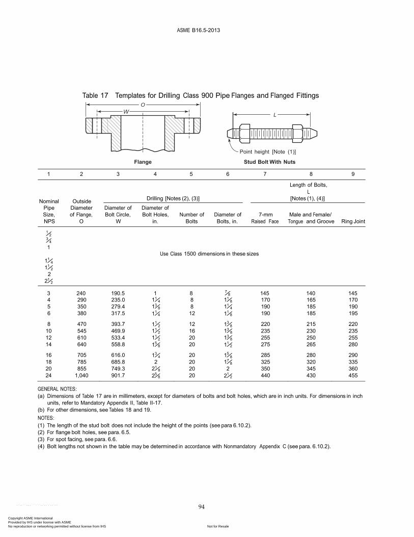
94
Table 17 Templates for Drilling Class 900 Pipe Flanges and Flanged Fittings O
L
Point height [Note (1)]
Flange Stud Bolt With Nuts
1 2 3 4 5 6 7 8 9
Length of Bolts, L
Nominal Outside Drilling [Notes (2), (3)] [Notes (1), (4)]
Pipe Diameter Diameter of Diameter of Size, of Flange, Bolt Circle, Bolt Holes, Number of Diameter of 7-mm Male and Female/ NPS O W in. Bolts Bolts, in. Raised Face Tongue and Groove Ring Joint
1⁄2 3⁄4
1
11⁄4
11⁄2
2 21⁄2
Use Class 1500 dimensions in these sizes
3 240 190.5 1 8 7⁄8 145 140 145 4 290 235.0 11⁄4 8 11⁄8 170 165 170 5 350 279.4 13⁄8 8 11⁄4 190 185 190 6 380 317.5 11⁄4 12 11⁄8 190 185 195 8 470 393.7 11⁄2 12 13⁄8 220 215 220
10 545 469.9 11⁄2 16 13⁄8 235 230 235 12 610 533.4 11⁄2 20 13⁄8 255 250 255 14 640 558.8 15⁄8 20 11⁄2 275 265 280 16 705 616.0 13⁄4 20 15⁄8 285 280 290 18 785 685.8 2 20 17⁄8 325 320 335 20 855 749.3 21⁄8 20 2 350 345 360 24 1,040 901.7 25⁄8 20 21⁄2 440 430 455
GENERAL NOTES: (a) Dimensions of Table 17 are in millimeters, except for diameters of bolts and bolt holes, which are in inch units. For dimensions in inch
units, refer to Mandatory Appendix II, Table II-17. (b) For other dimensions, see Tables 18 and 19. NOTES: (1) The length of the stud bolt does not include the height of the points (see para 6.10.2). (2) For flange bolt holes, see para. 6.5. (3) For spot facing, see para. 6.6. (4) Bolt lengths not shown in the table may be determined in accordance with Nonmandatory Appendix C (see para. 6.10.2).
Copyright ASME International Provided by IHS under license with ASME
Not for ResaleNo reproduction or networking permitted without license from IHS
--`,,```,,,,````-`-`,,`,,`,`,,`---
ASM
E B16.5-2013
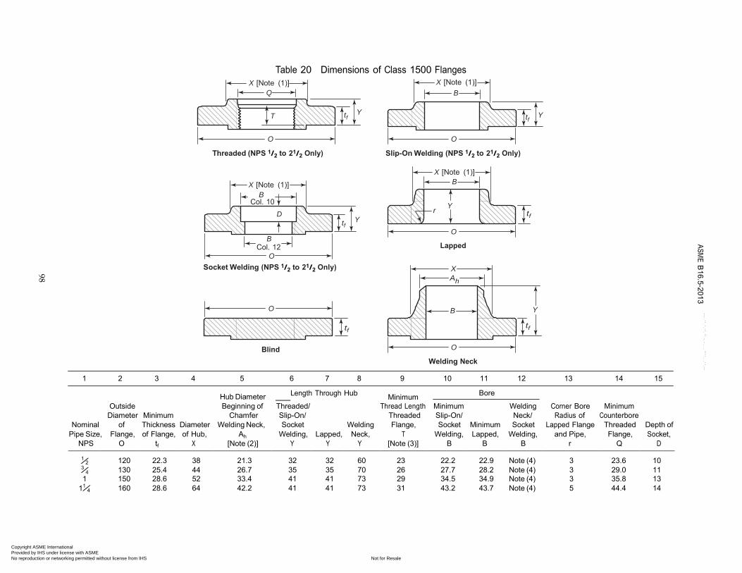
98
Table 20 Dimensions of Class 1500 Flanges
X [Note (1)] Q
T
tf
Y
X [Note (1)] B
tf
Y
O
Threaded (NPS 1/2 to 21/2 Only)
O Slip-On Welding (NPS 1/2 to 21/2 Only)
X [Note (1)]
B Col. 10
D tf
Y
B Col. 12
O Socket Welding (NPS 1/2 to 21/2 Only)
O
tf
X [Note (1)] B
r
Y tf
O
Lapped
X
Ah
B Y
tf
Blind O
Welding Neck
1 2 3 4 5 6 7 8 9 10 11 12 13 14 15
Hub Diameter Length Through Hub Minimum
Bore
Outside Beginning of Threaded/ Thread Length Minimum Welding Corner Bore Minimum Diameter Minimum Chamfer Slip-On/ Threaded Slip-On/ Neck/ Radius of Counterbore
Nominal of Thickness Diameter Welding Neck, Socket Welding Flange, Socket Minimum Socket Lapped Flange Threaded Depth of Pipe Size, Flange, of Flange, of Hub, Ah Welding, Lapped, Neck, T Welding, Lapped, Welding, and Pipe, Flange, Socket,
NPS O tf X [Note (2)] Y Y Y [Note (3)] B B B r Q D
1⁄2 3⁄4
120
22.3
38
21.3
32
32
60
23
22.2
22.9
Note (4)
3
23.6
10 130 25.4 44 26.7 35 35 70 26 27.7 28.2 Note (4) 3 29.0 11
1 150 28.6 52 33.4 41 41 73 29 34.5 34.9 Note (4) 3 35.8 13 11⁄4 160 28.6 64 42.2 41 41 73 31 43.2 43.7 Note (4) 5 44.4 14
Copyright ASME International Provided by IHS under license with ASME
Not for ResaleNo reproduction or networking permitted without license from IHS
--`,,```,,,,````-`-`,,`,,`,`,,`---

ASME B
16.5-2013
99
Table 20 Dimensions of Class 1500 Flanges (Cont’d)
1 2 3 4 5 6 7 8 9 10 11 12 13 14 15 Hub Diameter Length Through Hub
Minimum Bore
Outside Beginning of Threaded/ Thread Length Minimum Welding Corner Bore Minimum Diameter Minimum Chamfer Slip-On/ Threaded Slip-On/ Neck/ Radius of Counterbore
Nominal of Thickness Diameter Welding Neck, Socket Welding Flange, Socket Minimum Socket Lapped Flange Threaded Depth of Pipe Size, Flange, of Flange, of Hub, Ah Welding, Lapped, Neck, T Welding, Lapped, Welding, and Pipe, Flange, Socket,
NPS O tf X [Note (2)] Y Y Y [Note (3)] B B B r Q D
11⁄2 180 31.8 70 48.3 44 44 83 32 49.5 50.0 Note (4) 6 50.6 16 2 215 38.1 105 60.3 57 57 102 39 61.9 62.5 Note (4) 8 63.5 17
21⁄2 245 41.3 124 73.0 64 64 105 48 74.6 75.4 Note (4) 8 76.2 19 3 265 47.7 133 88.9 . . . 73 117 . . . . . . 91.4 Note (4) 10 . . . . . . 4 310 54.0 162 114.3 . . . 90 124 . . . . . . 116.8 Note (4) 11 . . . . . .
5 375 73.1 197 141.3 . . . 105 156 . . . . . . 144.4 Note (4) 11 . . . . . . 6 395 82.6 229 168.3 . . . 119 171 . . . . . . 171.4 Note (4) 13 . . . . . . 8 485 92.1 292 219.1 . . . 143 213 . . . . . . 222.2 Note (4) 13 . . . . . . 10 585 108.0 368 273.0 . . . 178 254 . . . . . . 277.4 Note (4) 13 . . . . . . 12 675 123.9 451 323.8 . . . 219 283 . . . . . . 328.2 Note (4) 13 . . . . . .
14 750 133.4 495 355.6 . . . 241 298 . . . . . . 360.2 Note (4) 13 . . . . . . 16 825 146.1 552 406.4 . . . 260 311 . . . . . . 411.2 Note (4) 13 . . . . . . 18 915 162.0 597 457.0 . . . 276 327 . . . . . . 462.3 Note (4) 13 . . . . . . 20 985 177.8 641 508.0 . . . 292 356 . . . . . . 514.4 Note (4) 13 . . . 24 1 170 203.2 762 610.0 . . . 330 406 . . . . . . 616.0 Note (4) 13 . . . . . .
GENERAL NOTES: (a) Dimensions of Table 20 are in millimeters. For dimensions in inch units, refer to Mandatory Appendix II, Table II-20. (b) For tolerances, see section 7. (c) For facings, see para. 6.4. (d) For flange bolt holes, see para. 6.5 and Table 19. (e) For spot facing, see para 6.6. (f) For reducing threaded and slip-on flanges, see Table 6. (g) Blind flanges may be made with or without hubs at the manufacturer’s option. (h) For reducing welding neck flanges, see para 6.8. NOTES: (1) This dimension is for the large end of the hub, which may be straight or tapered. Taper shall not exceed 7 deg on threaded, slip-on, socket-welding, and lapped flanges. This dimen-
sion is defined as the diameter at the intersection between the hub taper and back face of the flange. (2) For welding end bevel, see para. 6.7. (3) For thread of threaded flanges, see para. 6.9. (4) To be specified by the Purchaser.
Copyright ASME International Provided by IHS under license with ASME
Not for ResaleNo reproduction or networking permitted without license from IHS
--`,,```,,,,````-`-`,,`,,`,`,,`---

ASME B16.5-2013
97
120
82.6
130 88.9 150 101.6 160 111.1
Table 19 Templates for Drilling Class 1500 Pipe Flanges O
L
Point height [Note (1)]
Flange Stud Bolt With Nuts 1 2 3 4 5 6 7 8 9
Outside
Length of Bolts, L
Drilling [Notes (2), (3)] [Notes (1), (4)]
Nominal Diameter Diameter of Diameter of Diameter of Pipe Size, of Flange, Bolt Circle, Bolt Holes, Number of Bolts, 7-mm Male and Female/
NPS O W in. Bolts in. Raised Face Tongue and Groove Ring Joint 1⁄2 3⁄4
1 11⁄4
7⁄8 4 3⁄4 110 100 110 7⁄8 4 3⁄4 115 110 115 1 4 7⁄8 125 120 125 1 4 7⁄8 125 120 125
11⁄2 180 123.8 11⁄8 4 1 140 135 140 2 215 165.1 1 8 7⁄8 145 140 145
21⁄2 245 190.5 11⁄8 8 1 160 150 160 3 265 203.2 11⁄4 8 11⁄8 180 170 180 4 310 241.3 13⁄8 8 11⁄4 195 190 195
5 375 292.1 15⁄8 8 11⁄2 250 240 250 6 395 317.5 11⁄2 12 13⁄8 260 255 265 8 485 393.7 13⁄4 12 15⁄8 290 285 300 10 585 482.6 2 12 17⁄8 335 330 345 12 675 571.5 21⁄8 16 2 375 370 385
14 750 635.0 23⁄8 16 21⁄4 405 400 425 16 825 704.8 25⁄8 16 21⁄2 445 440 470 18 915 774.7 27⁄8 16 23⁄4 495 490 525 20 985 831.8 31⁄8 16 3 540 535 565 24 1 170 990.6 35⁄8 16 31⁄2 615 610 650
GENERAL NOTES: (a) Dimensions of Table 19 are in millimeters, except for the diameters of the bolts and bolt holes, which are in inch units. For dimensions
in inch units, refer to Mandatory Appendix II, Table II-19. (b) For other dimensions, see Table 20. NOTES: (1) The length of the stud bolt does not include the height of the points (see para. 6.10.2). (2) For flange bolt holes, see para. 6.5. (3) For spot facing, see para. 6.6. (4) Bolt lengths not shown in the table may be determined in accordance with Nonmandatory Appendix C (see para. 6.10.2).
Copyright ASME International Provided by IHS under license with ASME
Not for ResaleNo reproduction or networking permitted without license from IHS
--`,,```,,,,````-`-`,,`,,`,`,,`---
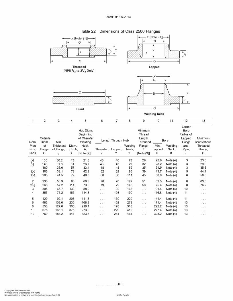
ASME B16.5-2013
101
Table 22 Dimensions of Class 2500 Flanges
X [Note (1)] Q
X [Note (1)]
B
T tf Y
r Y
tf
O
Threaded (NPS 1/2 to 21/2 Only)
O
Lapped
X
Ah
O B Y
tf tf
Blind O
Welding Neck
1 2 3 4 5 6 7 8 9 10 11 12 13
Corner
Hub Diam. Minimum Bore Beginning Thread Radius of
Outside of Chamfer Length Lapped Minimum Nom. Diam. Min. Welding Length Through Hub Threaded Bore Flange Counterbore Pipe of Thickness Diam. Neck, Welding Flange, Min. Welding and Threaded Size, Flange, of Flange, of Hub, Ah Threaded, Lapped, Neck, T Lapped, Neck, Pipe, Flange, NPS O tf X [Note (2)] Y Y Y [Note (3)] B B r Q
1⁄2 135 30.2 43 21.3 40 40 73 3⁄4 140 31.8 51 26.7 43 43 79
29
22.9
Note (4)
3
23.6 32 28.2 Note (4) 3 29.0
1 160 35.0 57 33.4 48 48 89 35 34.9 Note (4) 3 35.8 11⁄4 185 38.1 73 42.2 52 52 95 39 43.7 Note (4) 5 44.4 11⁄2 205 44.5 79 48.3 60 60 111 45 50.0 Note (4) 6 50.6 2 235 50.9 95 60.3 70 70 127 51 62.5 Note (4) 8 63.5
21⁄2 265 57.2 114 73.0 79 79 143 58 75.4 Note (4) 8 76.2 3 305 66.7 133 88.9 . . . 92 168 . . . 91.4 Note (4) 10 . . . 4 355 76.2 165 114.3 . . . 108 190 . . . 116.8 Note (4) 11 . . . 5 420 92.1 203 141.3 . . . 130 229 . . . 144.4 Note (4) 11 . . . 6 485 108.0 235 168.3 . . . 152 273 . . . 171.4 Note (4) 13 . . . 8 550 127.0 305 219.1 . . . 178 318 . . . 222.2 Note (4) 13 . . .
10 675 165.1 375 273.0 . . . 229 419 . . . 277.4 Note (4) 13 . . . 12 760 184.2 441 323.8 . . . 254 464 . . . 328.2 Note (4) 13 . . .
Copyright ASME International Provided by IHS under license with ASME
Not for ResaleNo reproduction or networking permitted without license from IHS
--`,,```,,,,````-`-`,,`,,`,`,,`---
ASME B16.5-2013
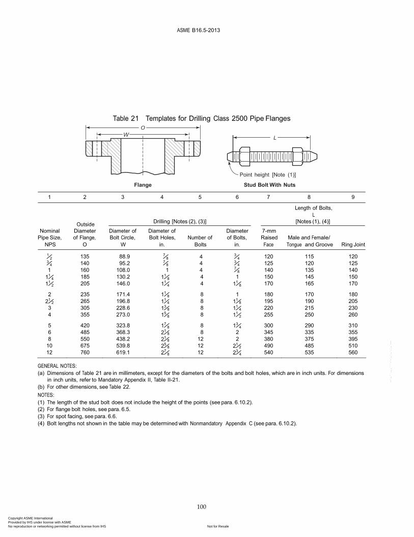
100
135
88.9
140 95.2 160 108.0
Table 21 Templates for Drilling Class 2500 Pipe Flanges O
L
Point height [Note (1)]
Flange Stud Bolt With Nuts
1 2 3 4 5 6 7 8 9
Length of Bolts, L
Outside Drilling [Notes (2), (3)] [Notes (1), (4)]
Nominal Diameter Diameter of Diameter of Diameter 7-mm Pipe Size, of Flange, Bolt Circle, Bolt Holes, Number of of Bolts, Raised Male and Female/
NPS O W in. Bolts in. Face Tongue and Groove Ring Joint
1⁄2 7⁄8 4 3⁄4
3⁄4 7⁄8 4 3⁄4
1 1 4 7⁄8
120
115
120
125 120 125 140 135 140
11⁄4 185 130.2 11⁄8 4 1 150 145 150 11⁄2 205 146.0 11⁄4 4 11⁄8 170 165 170 2 235 171.4 11⁄8 8 1 180 170 180
21⁄2 265 196.8 11⁄4 8 11⁄8 195 190 205 3 305 228.6 13⁄8 8 11⁄4 220 215 230 4 355 273.0 15⁄8 8 11⁄2 255 250 260 5 420 323.8 17⁄8 8 13⁄4 300 290 310 6 485 368.3 21⁄8 8 2 345 335 355 8 550 438.2 21⁄8 12 2 380 375 395
10 675 539.8 25⁄8 12 21⁄2 490 485 510 12 760 619.1 27⁄8 12 23⁄4 540 535 560
GENERAL NOTES: (a) Dimensions of Table 21 are in millimeters, except for the diameters of the bolts and bolt holes, which are in inch units. For dimensions
in inch units, refer to Mandatory Appendix II, Table II-21. (b) For other dimensions, see Table 22. NOTES: (1) The length of the stud bolt does not include the height of the points (see para. 6.10.2). (2) For flange bolt holes, see para. 6.5. (3) For spot facing, see para. 6.6. (4) Bolt lengths not shown in the table may be determined with Nonmandatory Appendix C (see para. 6.10.2).
Copyright ASME International Provided by IHS under license with ASME
Not for ResaleNo reproduction or networking permitted without license from IHS
--`,,```,,,,````-`-`,,`,,`,`,,`---
42
Siz
eB
olt
ing
Det
ails
Bo
ltin
g D
etai
lsW
eld
ing
Nec
kB
oss
Det
ails
DN
m
m
No
min
al
Pip
e S
ize
in
ch
Out
sid
eD
iam
eter
of
Flan
ge
A
Forg
ed
BC
DE
Met
ric
F
Wel
din
g
Nec
k F1
Tota
l Le
ngth
o
f N
eck
G
Dia
met
er
at S
mal
l E
nd o
f N
eck
H
Dia
met
er
at L
arg
e E
nd o
f N
eck
J
Leng
th
of
Bo
ss
Det
ails
K
Dia
met
er
of
Bo
ss
at S
mal
l E
nd
Min
. L
Dia
met
er
at R
oo
t o
f B
oss
M
ax.
M
151/
295
5*67
414
M12
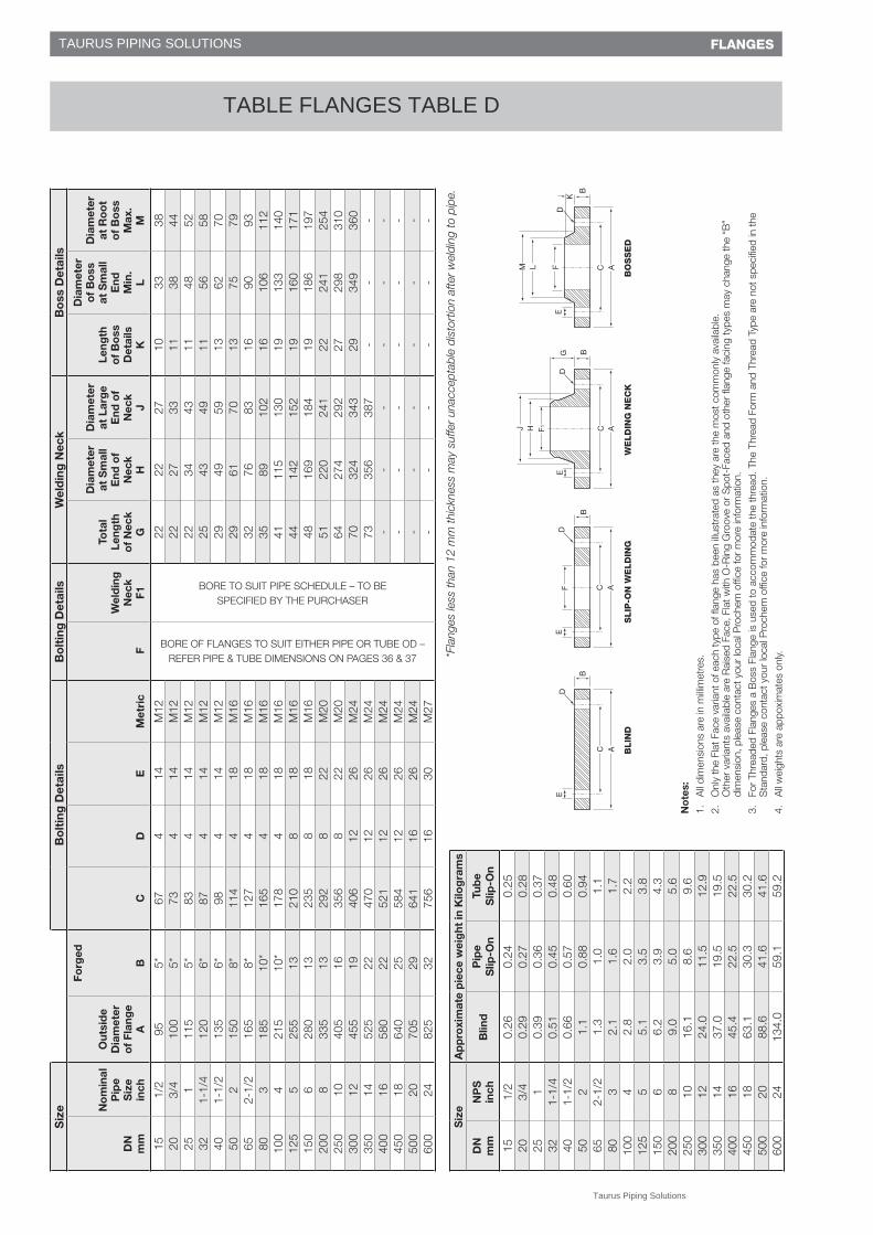
BORE OF FLANGES TO SUIT EITHER PIPE OR TUBE OD – REFER PIPE & TUBE DIMENSIONS ON PAGES 36 & 37
BORE TO SUIT PIPE SCHEDULE – TO BE SPECIFIED BY THE PURCHASER
2222
2710
3338
203/
410
05*
734
14M
1222
2733
1138
4425
111
55*
834
14M
1222
3443
1148
5232
1-1/
412
06*
874
14M
1225
4349
1156
5840
1-1/
213
56*
984
14M
1229
4959
1362
7050
215
08*
114
418
M16
2961
7013
7579
652-
1/2
165
8*12
74
18M
1632
7683
1690
9380
318
510
*16
54
18M
1635
8910
216
106
112
100
421
510
*17
84
18M
1641
115
130
1913
314
012
55
255
1321
08
18M
1644
142
152
1916
017
115
06
280
1323
58
18M
1648
169
184
1918
619
720
08
335
1329
28
22M
2051
220
241
2224
125
425
010
405
1635
68
22M
2064
274
292
2729
831
030
012
455
1940
612
26M
2470
324
343
2934
936
035
014
525
2247
012
26M
2473
356
387
--
-40
016
580
2252
112
26M
24-
--
--
-45
018
640
2558
412
26M
24-
--
--
-50
020
705
2964
116
26M
24-
--
--
-60
024
825
3275
616
30M
27-
--
--
-
*Fla
nges
less
than
12
mm
thic
knes
s m
ay s
uffe
r un
acce
ptab
le d
isto
rtio
n af
ter
wel
ding
to p
ipe.
Siz
eA
pp
roxi
mat
e p
iece
wei
ght
in K
ilog
ram
s
DN
m
mN
PS
in
chB
lind
Pip
e S
lip-O
nTu
be
Slip
-On
151/
20.
260.
240.
2520
3/4
0.29
0.27
0.28
251
0.39
0.36
0.37
321-
1/4
0.51
0.45
0.48
401-
1/2
0.66
0.57
0.60
502
1.1
0.88
0.94
652-
1/2
1.3
1.0
1.1
803
2.1
1.6
1.7
100
42.
82.
02.
212
55
5.1
3.5
3.8
150
66.
23.
94.
320
08
9.0
5.0
5.6
250
1016
.18.
69.
630
012
24.0
11.5
12.9
350
1437
.019
.519
.540
016
45.4
22.5
22.5
450
1863
.130
.330
.250
020
88.6
41.6
41.6
600
2413
4.0
59.1
59.2
No
tes:
1.
All
dim
ensi
ons
are
in m
illim
etre
s.
2.
Onl
y th
e Fl
at F
ace
varia
nt o
f eac
h ty
pe o
f flan
ge h
as b
een
illust
rate
d as
they
are
the
mos
t com
mon
ly a
vaila
ble.
O
ther
var
iant
s av
aila
ble
are
Rai
sed
Face
, Fla
t with
O-R
ing
Gro
ove
or S
pot-
Face
d an
d ot
her
flang
e fa
cing
type
s m
ay c
hang
e th
e “B
” di
men
sion
, ple
ase
cont
act y
our
loca
l Pro
chem
offi
ce fo
r m
ore
info
rmat
ion.
3.
For
Thre
aded
Fla
nges
a B
oss
Flan
ge is
use
d to
acc
omm
odat
e th
e th
read
. The
Thr
ead
Form
and
Thr
ead
Type
are
not
spe
cifie
d in
the
Sta
ndar
d, p
leas
e co
ntac
t you
r lo
cal P
roch
em o
ffice
for
mor
e in
form
atio
n.
4.
All
wei
ghts
are
app
oxim
ates
onl
y.
FLANGES
C BLIN
DS
LIP
-ON
WE
LD
ING
BO
SS
ED
WE
LD
ING
NE
CK
Taurus Piping Solutions
TAURUS PIPING SOLUTIONS
TABLE FLANGES TABLE D

43
Siz
eA
pp
roxi
mat
e p
iece
wei
ght
in K
ilog
ram
s
DN
m
mN
PS
in
chB
lind
Pip
e S
lip-O
nTu
be
Slip
-On
151/
20.
310.
290.
3020
3/4
0.35
0.32
0.33
251
0.55
0.50
0.52
321-
1/4
0.68
0.59
0.63
401-
1/2
0.99
0.85
0.90
502
1.3
1.1
1.2
652-
1/2
1.6
1.3
1.4
803
2.3
1.7
1.9
100
43.
62.
52.
712
55
5.5
3.7
4.1
150
68.
04.
95.
520
08
12.9
7.2
8.0
250
1021
.911
.613
.030
012
31.2
14.8
16.7
350
1448
.725
.725
.740
016
66.0
32.8
32.8
450
1887
.741
.841
.750
020
116.
154
.554
.560
024
200.
087
.887
.9
*Fla
nges
less
than
12
mm
thic
knes
s m
ay s
uffe
r un
acce
ptab
le d
isto
rtio
n af
ter
wel
ding
to p
ipe.
No
tes:
1.
All
dim
ensi
ons
are
in m
illim
etre
s.
2.
Onl
y th
e Fl
at F
ace
varia
nt o
f eac
h ty
pe o
f flan
ge h
as b
een
illust
rate
d as
they
are
the
mos
t com
mon
ly a
vaila
ble.
O
ther
var
iant
s av
aila
ble
are
Rai
sed
Face
, Fla
t with
O-R
ing
Gro
ove
or S
pot-
Face
d an
d ot
her
flang
e fa
cing
type
s m
ay c
hang
e th
e “B
” di
men
sion
, ple
ase
cont
act y
our
loca
l Pro
chem
offi
ce fo
r m
ore
info
rmat
ion.
3.
For
Thre
aded
Fla
nges
a B
oss
Flan
ge is
use
d to
acc
omm
odat
e th
e th
read
. The
Thr
ead
Form
and
Thr
ead
Type
are
not
spe
cifie
d in
the
Sta
ndar
d, p
leas
e co
ntac
t you
r lo
cal P
roch
em o
ffice
for
mor
e in
form
atio
n.
4.
All
wei
ghts
are
app
oxim
ates
onl
y.
Siz
eW
eld
ing
Nec
kB
oss
Det
ails
DN
m
m
No
min
al
Pip
e S
ize
inch
Out
sid
e D
iam
eter
o
f Fl
ang
e A
Forg
edo
r P
late
; T
hick
ness
o
f Fl
ang
e M
in.
B
Pit
ch
Cir
cle
D
iam
eter
C
Num
ber
o
f H
ole
s D
Dia
met
er
of
Ho
les
E
Dia
met
er
of
Bo
lts
Met
ric
Slip
-On
or
B
oss
ed
F
Wel
din
g
Nec
k F1
Tota
l Le
ngth
o
f N
eck
G
Dia
met
er
at S
mal
l E
nd o
f N
eck
H
Dia
met
er
at L
arg
e E
nd o
f N
eck
J
Leng
th
of
Bo
ss
Det
ails
K
Dia
met
er
of
Bo
ss
at S
mal
l E
nd
Min
. L
Dia
met
er
at R
oo
t o
f B
oss
M
ax.
M
151/
295
6*67
414
M12
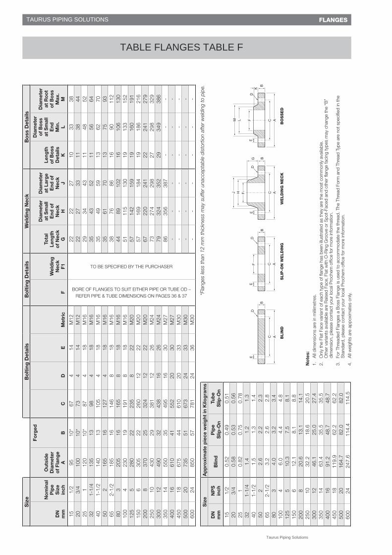
BORE OF FLANGES TO SUIT EITHER PIPE OR TUBE OD – REFER PIPE & TUBE DIMENSIONS ON PAGES 36 & 37
TO BE SPECIFIED BY THE PURCHASER
2222
2710
3338
203/
410
06*
734
14M
1222
2733
1138
4425
111
57*
834
14M
1222
3443
1148
5232
1-1/
412
08*
874
14M
1225
4349
1156
5840
1-1/
213
59*
984
14M
1229
4959
1362
7050
215
010
*11
44
18M
1629
6170
1375
7965
2-1/
216
510
*12
74
18M
1632
7683
1690
9380
318
511
*14
64
18M
1635
8910
216
106
112
100
421
513
178
818
M16
4110
213
019
133
140
125
525
514
210
818
M16
4414
215
219
160
171
150
628
017
235
822
M20
4816
918
419
186
191
200
833
519
292
822
M20
5122
024
122
241
249
250
1040
522
356
1222
M20
6427
429
227
298
310
300
1245
525
406
1226
M24
7032
434
329
349
354
350
1452
529
470
1226
M24
7335
638
7-
--
400
1658
032
521
1226
M24
--
--
--
450
1864
035
584
1626
M24
--
--
--
500
2070
538
641
1626
M24
--
--
--
600
2480
2548
756
1633
M30
--
--
--
FLANGES
C BLIN
DS
LIP
-ON
WE
LD
ING
BO
SS
ED
WE
LD
ING
NE
CK
Taurus Piping Solutions
TAURUS PIPING SOLUTIONS
TABLE FLANGES TABLE E
44
Siz
eB
olt
ing
Det
ails
Bo
ltin
g D
etai
lsW
eld
ing
Nec
kB
oss
Det
ails
DN
m
m
No
min
al
Pip
e S
ize
inch
Out
sid
eD
iam
eter
of
Flan
ge
A
Forg
ed
BC
DE
Met
ric
F
Wel
din
g
Nec
k F1
Tota
l Le
ngth
o
f N
eck
G
Dia
met
er
at S
mal
l E
nd o
f N
eck
H
Dia
met
er
at L
arg
e E
nd o
f N
eck
J
Leng
th
of
Bo
ss
Det
ails
K
Dia
met
er
of
Bo
ss
at S
mal
l E
nd
Min
. L
Dia
met
er
at R
oo
t o
f B
oss
M
ax.
M
151/
295
10*
674
14M
12
BORE OF FLANGES TO SUIT EITHER PIPE OR TUBE OD – REFER PIPE & TUBE DIMENSIONS ON PAGES 36 & 37
TO BE SPECIFIED BY THE PURCHASER
2222
2710
3338
203/
410
010
*73
414
M12
2227
3311
3844
251
120
10*
874
18M
1629
3443
1148
5232
1-1/
413
513
984
18M
1635
4352
1156
6440
1-1/
214
013
105
418
M16
3549
5913
6270
502
165
1612
74
18M
1635
6170
1375
9365
2-1/
218
516
146
818
M16
3876
8616
9011
280
320
516
165
818
M16
4489
102
1610
613
010
04
230
1919
18
18M
1651
115
130
1913
315
212
55
280
2223
58
22M
2057
142
159
1916
019
115
06
305
2226
012
22M
2057
169
184
1918
621
620
08
370
2532
412
22M
2067
220
241
2224
127
925
010
430
2938
112
26M
2473
274
298
2729
832
930
012
490
3243
816
26M
2479
324
352
2934
938
635
014
550
3549
516
30M
2786
356
387
--
-40
016
610
4155
220
30M
27-
--
--
-45
018
675
4461
020
33M
30-
--
--
-50
020
735
5167
324
33M
30-
--
--
-60
024
850
5778
124
36M
30-
--
--
-
FLANGES
*Fla
nges
less
than
12
mm
thic
knes
s m
ay s
uffe
r un
acce
ptab
le d
isto
rtio
n af
ter
wel
ding
to p
ipe.
No
tes:
1.
All
dim
ensi
ons
are
in m
illim
etre
s.
2.
Onl
y th
e Fl
at F
ace
varia
nt o
f eac
h ty
pe o
f flan
ge h
as b
een
illust
rate
d as
they
are
the
mos
t com
mon
ly a
vaila
ble.
O
ther
var
iant
s av
aila
ble
are
Rai
sed
Face
, Fla
t with
O-R
ing
Gro
ove
or S
pot-
Face
d an
d ot
her
flang
e fa
cing
type
s m
ay c
hang
e th
e “B
” di
men
sion
, ple
ase
cont
act y
our
loca
l Pro
chem
offi
ce fo
r m
ore
info
rmat
ion.
3.
For
Thre
aded
Fla
nges
a B
oss
Flan
ge is
use
d to
acc
omm
odat
e th
e th
read
. The
Thr
ead
Form
and
Thr
ead
Type
are
not
spe
cifie
d in
the
Sta
ndar
d, p
leas
e co
ntac
t you
r lo
cal P
roch
em o
ffice
for
mor
e in
form
atio
n.
4.
All
wei
ghts
are
app
oxim
ates
onl
y.
Siz
eA
pp
roxi
mat
e p
iece
wei
ght
in K
ilog
ram
s
DN
m
mN
PS
in
chB
lind
Pip
e S
lip-O
nTu
be
Slip
-On
151/
20.
520.
490.
5120
3/4
0.58
0.53
0.56
251
0.82
0.75
0.78
321-
1/4
1.4
1.2
1.3
401-
1/2
1.5
1.3
1.4
502
2.6
2.2
2.3
652-
1/2
3.2
2.6
2.8
803
4.0
3.2
3.4
100
46.
04.
44.
812
55
10.3
7.5
8.1
150
612
.18.
18.
820
08
20.6
13.1
14.1
250
1032
.218
.620
.530
012
46.1
25.0
27.4
350
1463
.435
.535
.540
016
91.2
48.7
48.7
450
1811
9.9
62.2
62.2
500
2016
4.7
82.0
82.0
600
2424
7.6
114.
411
4.5
C BLIN
DS
LIP
-ON
WE
LD
ING
BO
SS
ED
WE
LD
ING
NE
CK
Taurus Piping Solutions
TAURUS PIPING SOLUTIONS
TABLE FLANGES TABLE F
45© PROCHEM PIPELINE PRODUCTS – MAY 2013
Siz
eW
eld
ing
Nec
kB
oss
Det
ails
DN
(m
etri
c)
No
min
al
Pip
e S
ize
(inch
)
Out
sid
e D
iam
eter
o
f Fl
ang
e A
Forg
edo
r P
late
; T
hick
ness
o
f Fl
ang
e M
in.
B
Pit
ch
Cir
cle
D
iam
eter
C
Num
ber
o
f H
ole
s D
Dia
met
er
of
Ho
les
E
Dia
met
er
of
Bo
lts
Met
ric
Slip
-On
or
B
oss
ed
F
Wel
din
g
Nec
k F1
Tota
l Le
ngth
o
f N
eck
G
Dia
met
er
at S
mal
l E
nd o
f N
eck
H
Dia
met
er
at L
arg
e E
nd o
f N
eck
J
Leng
th
of
Bo
ss
Det
ails
K
Dia
met
er
of
Bo
ss
at S
mal
l E
nd
Min
. L
Dia
met
er
at R
oo
t o
f B
oss
M
ax.
M
151/
211
513
834
18M
16
BORE OF FLANGES TO SUIT EITHER PIPE OR TUBE OD – REFER PIPE & TUBE DIMENSIONS ON PAGES 36 & 37
TO BE SPECIFIED BY THE PURCHASER
2922
3010
3348
203/
411
513
834
18M
1629
2735
1138
4825
112
014
874
18M
1629
3443
1148
5232
1-1/
413
517
984
18M
1635
4352
1156
6440
1-1/
214
017
105
418
M16
3549
5913
6270
502
165
1912
74
18M
1635
6170
1375
9365
2-1/
218
519
146
818
M16
3876
8616
9011
280
320
522
165
818
M16
4489
102
1610
613
010
04
230
2519
18
18M
1651
115
130
1913
315
212
55
280
2923
58
22M
2057
142
159
1916
019
115
06
305
2926
012
22M
2057
169
184
1918
621
620
08
370
3232
412
22M
2067
220
241
2224
127
925
010
430
3537
112
26M
2473
274
298
2729
832
930
012
490
4143
816
26M
2479
324
352
2934
938
635
014
550
4849
516
30M
2786
356
387
--
-40
016
610
5455
220
30M
27-
--
--
-45
018
675
6061
020
33M
30-
--
--
-50
020
735
6767
324
33M
30-
--
--
-60
024
850
7678
124
36M
33-
--
--
-
FLANGES
No
tes:
1.
All
dim
ensi
ons
are
in m
illim
etre
s.
2.
Onl
y th
e Fl
at F
ace
varia
nt o
f eac
h ty
pe o
f flan
ge h
as b
een
illust
rate
d as
they
are
the
mos
t com
mon
ly a
vaila
ble.
O
ther
var
iant
s av
aila
ble
are
Rai
sed
Face
, Fla
t with
O-R
ing
Gro
ove
or S
pot-
Face
d an
d ot
her
flang
e fa
cing
type
s m
ay c
hang
e th
e “B
” di
men
sion
, ple
ase
cont
act y
our
loca
l Pro
chem
offi
ce fo
r m
ore
info
rmat
ion.
3.
For
Thre
aded
Fla
nges
a B
oss
Flan
ge is
use
d to
acc
omm
odat
e th
e th
read
. The
Thr
ead
Form
and
Thr
ead
Type
are
not
spe
cifie
d in
the
Sta
ndar
d, p
leas
e co
ntac
t you
r lo
cal P
roch
em o
ffice
for
mor
e in
form
atio
n.
4.
All
wei
ghts
are
app
oxim
ates
onl
y.
Siz
eA
pp
roxi
mat
e p
iece
wei
ght
in K
ilog
ram
s
DN
m
mN
PS
in
chB
lind
Pip
e S
lip-O
nTu
be
Slip
-On
151/
20.
970.
940.
9620
3/4
0.97
0.92
0.94
251
1.2
1.1
1.1
321-
1/4
1.8
1.6
1.7
401-
1/2
2.0
1.7
1.8
502
3.1
2.7
2.8
652-
1/2
3.8
3.1
3.3
803
5.5
4.4
4.6
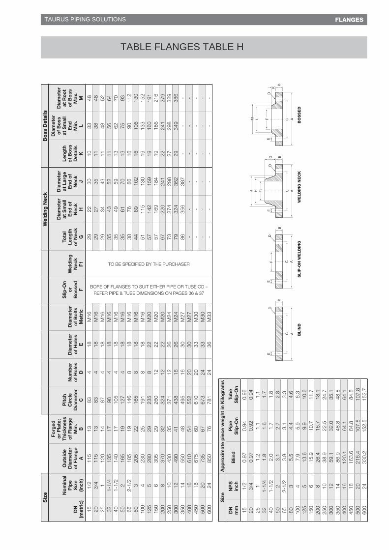
100
47.
95.
96.
312
55
13.6
9.9
10.6
150
615
.910
.711
.720
08
26.4
16.7
18.1
250
1038
.922
.524
.730
012
59.1
32.0
35.1
350
1486
.948
.848
.840
016
120.
164
.164
.145
018
163.
684
.884
.850
020
216.
410
7.8
107.
860
024
330.
215
2.5
152.
7
C BLIN
DS
LIP
-ON
WE
LD
ING
BO
SS
ED
WE
LD
ING
NE
CK
TAURUS PIPING SOLUTIONS
TABLE FLANGES TABLE H
47© PROCHEM PIPELINE PRODUCTS – MAY 2013
FLANGES
EN 1092-1 DIN FLANGES
PN 06
Size Bolting Details Bore Masses of flanges
DN mm
Nominal Pipe Size inch
Outside Diam.
of Flange
A
Forged or Plate;
Thickness of Flange
Min. B1-Type01
Forged or Plate;
Thickness of Flange
Min. B2-Type05
Pitch Circle Diam.
C
Number of
Holes D
Diam. of Holes
E
Diam. of Bolts
Bolts Metric
Diam. of
Raised Face
F
Height of
Raised Face
GSlip-On
HType 01
(kg)Type 05
(kg)
10 3/8 75 12 12 50 4 11 M10 35 2 BO
RE
OF FLA
NG
ES
TO S
UIT E
ITHE
R P
IPE
OR
TUB
E O
D -
RE
FER
PIP
E &
TUB
E D
IME
NS
ION
S O
N PA
GE
S 36 &
37
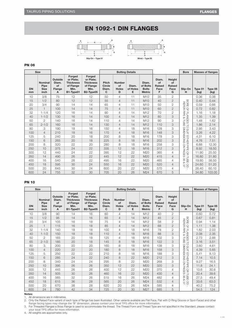
0.36 0.3815 1/2 80 12 12 55 4 11 M10 40 2 0.40 0.4420 3/4 90 14 14 65 4 11 M10 50 2 0.59 0.6625 1 100 14 14 75 4 11 M10 60 2 0.72 0.8232 1-1/4 120 16 14 90 4 14 M12 70 2 1.16 1.1840 1-1/2 130 16 14 100 4 14 M12 80 3 1.35 1.3950 2 140 16 14 110 4 14 M12 90 3 1.48 1.6265 2-1/2 160 16 14 130 4 14 M12 110 3 1.86 2.1480 3 190 18 16 150 4 18 M16 128 3 2.95 3.43100 4 210 18 16 170 4 18 M16 148 3 3.26 4.22125 5 240 20 18 200 8 18 M16 178 3 4.31 6.10150 6 265 20 18 225 8 18 M16 202 3 4.76 7.51200 8 320 22 20 280 8 18 M16 258 3 6.88 12.30250 10 375 24 22 335 12 18 M16 312 3 8.92 18.50300 12 440 24 22 395 12 22 M20 365 4 11.90 25.50350 14 490 26 22 445 12 22 M20 415 4 16.80 31.80400 16 540 28 22 495 16 22 M20 465 4 19.80 38.50450 18 595 30 24 550 16 22 M20 520 4 24.60 51.20500 20 645 30 24 600 20 22 M20 570 4 26.40 60.10600 24 755 32 30 705 20 26 M24 670 5 34.80 103.00
PN 10
Size Bolting Details Bore Masses of flanges
DN mm
Nominal Pipe Size inch
Outside Diam.
of Flange
A
Forged or Plate;
Thickness of Flange
Min. B1-Type01
Forged or Plate;
Thickness of Flange
Min. B2-Type05
Pitch Circle Diam.
C
Number of
Holes D
Diam. of Holes
E
Diam. of Bolts
Bolts Metric
Diam. of
Raised Face
F
Height of
Raised Face
GSlip-On
HType 01
(kg)Type 05
(kg)
10 3/8 90 14 16 60 4 14 M12 40 2 BO
RE
OF FLA
NG
ES
TO S
UIT E
ITHE
R P
IPE
OR
TUB
E O
D -
RE
FER
PIP
E &
TUB
E D
IME
NS
ION
S O
N PA
GE
S 36 &
37
0.60 0.7215 1/2 95 14 16 65 4 14 M12 45 2 0.67 0.8120 3/4 105 16 18 75 4 14 M12 58 2 0.94 1.1425 1 115 16 18 85 4 14 M12 68 2 1.11 1.3832 1-1/4 140 18 18 100 4 18 M16 78 2 1.82 2.0340 1-1/2 150 18 18 110 4 18 M16 88 3 2.08 2.3550 2 165 20 18 125 4 18 M16 102 3 2.73 2.8865 2-1/2 185 20 18 145 8 18 M16 122 3 3.16 3.5180 3 200 20 20 160 8 18 M16 138 3 3.60 4.61100 4 220 22 20 180 8 18 M16 158 3 4.39 5.65125 5 250 22 22 210 8 18 M16 188 3 5.41 8.13150 6 285 24 22 240 8 22 M20 212 3 7.14 10.5200 8 340 24 24 295 8 22 M20 268 3 9.27 16.5250 10 395 26 26 350 12 22 M20 320 3 11.8 24.1300 12 445 26 26 400 12 22 M20 370 4 13.6 30.8350 14 505 30 26 460 16 22 M20 430 4 20.4 39.6400 16 565 32 26 515 16 26 M24 482 4 27.5 49.4450 18 615 36 28 565 20 26 M24 532 4 33.6 63.0500 20 670 38 28 620 20 26 M24 585 4 40.2 75.2600 24 780 42 34 725 20 30 M27 685 5 54.5 124
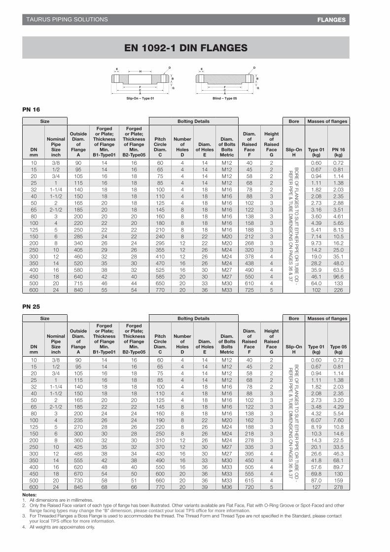
Notes:1. All dimensions are in millimetres.2. Only the Raised Face variant of each type of flange has been illustrated. Other variants available are Flat Face, Flat with O-Ring Groove or Spot-Faced and other
3. For Threaded Flanges a Boss Flange is used to accommodate the thread. The Thread Form and Thread Type are not specified in the Standard, please contact
4. All weights are appoximates only.
Blind – Type 05
B
D
G
A CF
E
Slip-On – Type 01
B
D
G
A CF
HE
flange facing types may change the “B” dimension, please contact your local TPS office for more information.
your local TPS office for more information.
TAURUS PIPING SOLUTIONS
48 © PROCHEM PIPELINE PRODUCTS – MAY 2013
FLANGES
PN 16
Size Bolting Details Bore Masses of flanges
DN mm
Nominal Pipe Size inch
Outside Diam.
of Flange
A
Forged or Plate;
Thickness of Flange
Min. B1-Type01
Forged or Plate;
Thickness of Flange
Min. B2-Type05
Pitch Circle Diam.
C
Number of
Holes D
Diam. of Holes
E
Diam. of Bolts
Bolts Metric
Diam. of
Raised Face
F
Height of
Raised Face
GSlip-On
HType 01
(kg)PN 16 (kg)
10 3/8 90 14 16 60 4 14 M12 40 2 BO
RE
OF FLA
NG
ES
TO S
UIT E
ITHE
R P
IPE
OR
TUB
E O
D -
RE
FER
PIP
E &
TUB
E D
IME
NS
ION
S O
N PA
GE
S 36 &
37
0.60 0.7215 1/2 95 14 16 65 4 14 M12 45 2 0.67 0.8120 3/4 105 16 18 75 4 14 M12 58 2 0.94 1.1425 1 115 16 18 85 4 14 M12 68 2 1.11 1.3832 1-1/4 140 18 18 100 4 18 M16 78 2 1.82 2.0340 1-1/2 150 18 18 110 4 18 M16 88 3 2.08 2.3550 2 165 20 18 125 4 18 M16 102 3 2.73 2.8865 2-1/2 185 20 18 145 8 18 M16 122 3 3.16 3.5180 3 200 20 20 160 8 18 M16 138 3 3.60 4.61100 4 220 22 20 180 8 18 M16 158 3 4.39 5.65125 5 250 22 22 210 8 18 M16 188 3 5.41 8.13150 6 285 24 22 240 8 22 M20 212 3 7.14 10.5200 8 340 26 24 295 12 22 M20 268 3 9.73 16.2250 10 405 29 26 355 12 26 M24 320 3 14.2 25.0300 12 460 32 28 410 12 26 M24 378 4 19.0 35.1350 14 520 35 30 470 16 26 M24 438 4 28.2 48.0400 16 580 38 32 525 16 30 M27 490 4 35.9 63.5450 18 640 42 40 585 20 30 M27 550 4 46.1 96.6500 20 715 46 44 650 20 33 M30 610 4 64.0 133600 24 840 55 54 770 20 36 M33 725 5 102 226
PN 25
Size Bolting Details Bore Masses of flanges
DN mm
Nominal Pipe Size inch
Outside Diam.
of Flange
A
Forged or Plate;
Thickness of Flange
Min. B1-Type01
Forged or Plate;
Thickness of Flange
Min. B2-Type05
Pitch Circle Diam.
C
Number of
Holes D
Diam. of Holes
E
Diam. of Bolts
Bolts Metric
Diam. of
Raised Face
F
Height of
Raised Face
GSlip-On
HType 01
(kg)Type 05
(kg)
10 3/8 90 14 16 60 4 14 M12 40 2 BO
RE
OF FLA
NG
ES
TO S
UIT E
ITHE
R P
IPE
OR
TUB
E O
D -
RE
FER
PIP
E &
TUB
E D
IME
NS
ION
S O
N PA
GE
S 36 &
37
0.60 0.7215 1/2 95 14 16 65 4 14 M12 45 2 0.67 0.8120 3/4 105 16 18 75 4 14 M12 58 2 0.94 1.1425 1 115 16 18 85 4 14 M12 68 2 1.11 1.3832 1-1/4 140 18 18 100 4 18 M16 78 2 1.82 2.0340 1-1/2 150 18 18 110 4 18 M16 88 3 2.08 2.3550 2 165 20 20 125 4 18 M16 102 3 2.73 3.2065 2-1/2 185 22 22 145 8 18 M16 122 3 3.48 4.2980 3 200 24 24 160 8 18 M16 138 3 4.32 5.54100 4 235 26 24 190 8 22 M20 162 3 6.07 7.60125 5 270 28 26 220 8 26 M24 188 3 8.19 10.8150 6 300 30 28 250 8 26 M24 218 3 10.3 14.6200 8 360 32 30 310 12 26 M24 278 3 14.3 22.5250 10 425 35 32 370 12 30 M27 335 3 20.1 33.5300 12 485 38 34 430 16 30 M27 395 4 26.6 46.3350 14 555 42 38 490 16 33 M30 450 4 41.8 68.1400 16 620 48 40 550 16 36 M33 505 4 57.6 89.7450 18 670 54 50 600 20 36 M33 555 4 69.8 130500 20 730 58 51 660 20 36 M33 615 4 87.0 159600 24 845 68 66 770 20 39 M36 720 5 127 278
Notes:1. All dimensions are in millimetres.2. Only the Raised Face variant of each type of flange has been illustrated. Other variants available are Flat Face, Flat with O-Ring Groove or Spot-Faced and other
3. For Threaded Flanges a Boss Flange is used to accommodate the thread. The Thread Form and Thread Type are not specified in the Standard, please contact
4. All weights are appoximates only.
EN 1092-1 DIN FLANGES
Blind – Type 05
B
D
G
A CF
E
Slip-On – Type 01
B
D
G
A CF
HE
flange facing types may change the “B” dimension, please contact your local TPS office for more information.
your local TPS office for more information.
TAURUS PIPING SOLUTIONS
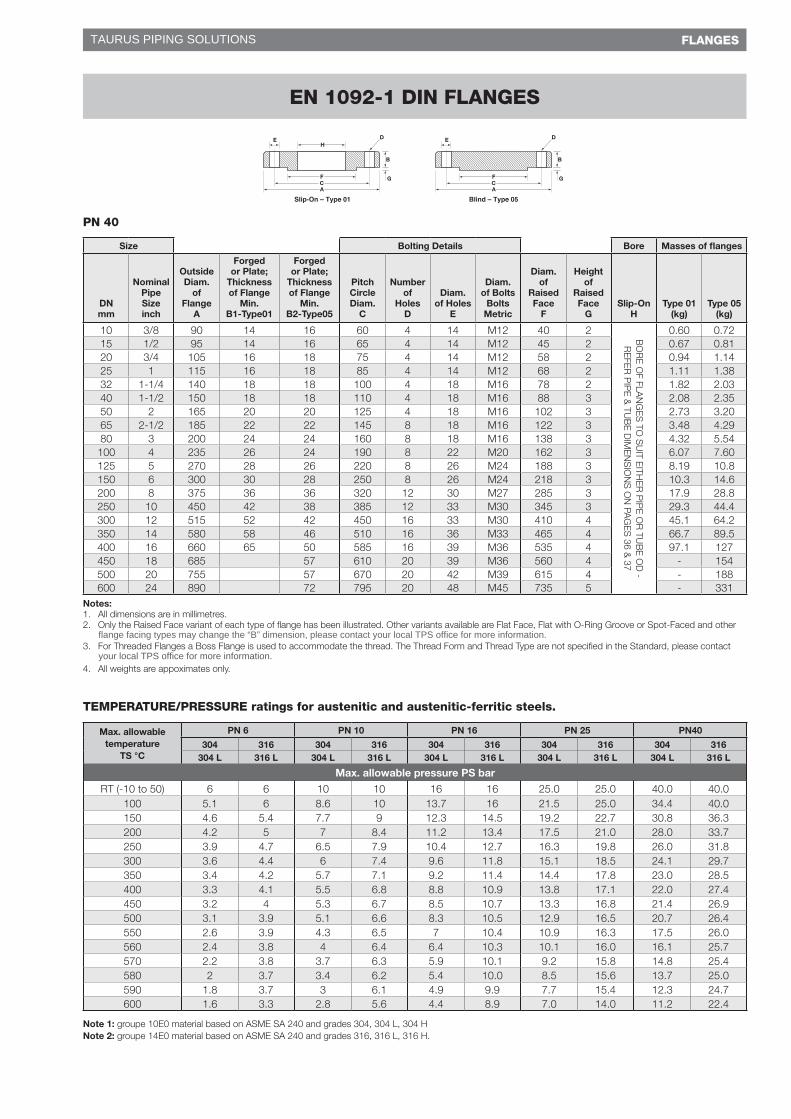
49© PROCHEM PIPELINE PRODUCTS – MAY 2013
FLANGES
PN 40
Size Bolting Details Bore Masses of flanges
DN mm
Nominal Pipe Size inch
Outside Diam.
of Flange
A
Forged or Plate;
Thickness of Flange
Min. B1-Type01
Forged or Plate;
Thickness of Flange
Min. B2-Type05
Pitch Circle Diam.
C
Number of
Holes D
Diam. of Holes
E
Diam. of Bolts
Bolts Metric
Diam. of
Raised Face
F
Height of
Raised Face
GSlip-On
HType 01
(kg)Type 05
(kg)
10 3/8 90 14 16 60 4 14 M12 40 2 BO
RE
OF FLA
NG
ES
TO S
UIT E
ITHE
R P
IPE
OR
TUB
E O
D -
RE
FER
PIP
E &
TUB
E D
IME
NS
ION
S O
N PA
GE
S 36 &
37
0.60 0.7215 1/2 95 14 16 65 4 14 M12 45 2 0.67 0.8120 3/4 105 16 18 75 4 14 M12 58 2 0.94 1.1425 1 115 16 18 85 4 14 M12 68 2 1.11 1.3832 1-1/4 140 18 18 100 4 18 M16 78 2 1.82 2.0340 1-1/2 150 18 18 110 4 18 M16 88 3 2.08 2.3550 2 165 20 20 125 4 18 M16 102 3 2.73 3.2065 2-1/2 185 22 22 145 8 18 M16 122 3 3.48 4.2980 3 200 24 24 160 8 18 M16 138 3 4.32 5.54100 4 235 26 24 190 8 22 M20 162 3 6.07 7.60125 5 270 28 26 220 8 26 M24 188 3 8.19 10.8150 6 300 30 28 250 8 26 M24 218 3 10.3 14.6200 8 375 36 36 320 12 30 M27 285 3 17.9 28.8250 10 450 42 38 385 12 33 M30 345 3 29.3 44.4300 12 515 52 42 450 16 33 M30 410 4 45.1 64.2350 14 580 58 46 510 16 36 M33 465 4 66.7 89.5400 16 660 65 50 585 16 39 M36 535 4 97.1 127450 18 685 57 610 20 39 M36 560 4 - 154500 20 755 57 670 20 42 M39 615 4 - 188600 24 890 72 795 20 48 M45 735 5 - 331
Notes:1. All dimensions are in millimetres.2. Only the Raised Face variant of each type of flange has been illustrated. Other variants available are Flat Face, Flat with O-Ring Groove or Spot-Faced and other
3. For Threaded Flanges a Boss Flange is used to accommodate the thread. The Thread Form and Thread Type are not specified in the Standard, please contact
4. All weights are appoximates only.
TEMPERATURE/PRESSURE ratings for austenitic and austenitic-ferritic steels.
Max. allowable temperature
TS °C
PN 6 PN 10 PN 16 PN 25 PN40
304 316 304 316 304 316 304 316 304 316304 L 316 L 304 L 316 L 304 L 316 L 304 L 316 L 304 L 316 L
Max. allowable pressure PS bar
RT (-10 to 50) 6 6 10 10 16 16 25.0 25.0 40.0 40.0100 5.1 6 8.6 10 13.7 16 21.5 25.0 34.4 40.0150 4.6 5.4 7.7 9 12.3 14.5 19.2 22.7 30.8 36.3200 4.2 5 7 8.4 11.2 13.4 17.5 21.0 28.0 33.7250 3.9 4.7 6.5 7.9 10.4 12.7 16.3 19.8 26.0 31.8300 3.6 4.4 6 7.4 9.6 11.8 15.1 18.5 24.1 29.7350 3.4 4.2 5.7 7.1 9.2 11.4 14.4 17.8 23.0 28.5400 3.3 4.1 5.5 6.8 8.8 10.9 13.8 17.1 22.0 27.4450 3.2 4 5.3 6.7 8.5 10.7 13.3 16.8 21.4 26.9500 3.1 3.9 5.1 6.6 8.3 10.5 12.9 16.5 20.7 26.4550 2.6 3.9 4.3 6.5 7 10.4 10.9 16.3 17.5 26.0560 2.4 3.8 4 6.4 6.4 10.3 10.1 16.0 16.1 25.7570 2.2 3.8 3.7 6.3 5.9 10.1 9.2 15.8 14.8 25.4580 2 3.7 3.4 6.2 5.4 10.0 8.5 15.6 13.7 25.0590 1.8 3.7 3 6.1 4.9 9.9 7.7 15.4 12.3 24.7600 1.6 3.3 2.8 5.6 4.4 8.9 7.0 14.0 11.2 22.4
Note 1: groupe 10E0 material based on ASME SA 240 and grades 304, 304 L, 304 HNote 2: groupe 14E0 material based on ASME SA 240 and grades 316, 316 L, 316 H.
EN 1092-1 DIN FLANGES
Blind – Type 05
B
D
G
A CF
E
Slip-On – Type 01
B
D
G
A CF
HE
flange facing types may change the “B” dimension, please contact your local TPS office for more information.
your local TPS office for more information.
TAURUS PIPING SOLUTIONS