tate automatic landings and to the horizontal - nasahistory.nasa.gov/asap/1976-2-3.pdf ·...
TRANSCRIPT

tate automatic landings and to the horizontal situation indicators
in the cockpit which are used as navigation aids for manual landings.
Manual landings are currently planned during ALT flights with temporary
engagement of the autoland system at higher altitudes.
vides elevation and azimuth angles within f 0.05 degrees and slant
range within -. 100 feet. Single MSBLS data is not used until after
separation, there are no concerns associated with mated flight activ-
ities.
The MSBLS pro-
+
The Safety Division has conducted a hazard analysis of the MSBLS
and conducted inspections of the DFRC facility.
being tracked as a result of these activities. These include (1) the
inability to verify antenna pointing and distance measurement accuracy
in the relatively short period between orbiter drops and shuttle train-
ing aircraft runs, (2) unexplained deviations in antenna pointing
accuracy which have occurred at DFRC, and (3) inability to verify the
MSBLS ground station accuracy because ground station errors cannot be
separated from overall system errors. Recommendations to resolve
Items 1 and 2 above have been submitted to the tracking and comni-
cations development division. Studies have been directed to resolve
the third issue as a result of several RID'S submitted at the ALT CDR
conducted in April 1976.
Several issues are
No issues have been identified relative to reliability of oper-
ation because of system redundancy, the short duration of the orbiter
free flight, and the various system verifications, including those per-
,formed during the captive/active flights.
10 1
Delivery of waveguides has been impaired because of poor quality
control. Rejection of waveguides has delayed start of qualification
tests. If problems continue, certification of wave-guides for ALT
may be impacted.
No issues have been identified relative to MSBLS integration in-
to a combined autoland with manual takeover. Since MSBLS data is al-
ways displayed in the cockpit, there is no real transition in MSBLS
when going from auto to manual.
Q. An ALT data-link systems review was conducted earlier at
Palmdale. It was to serve as the final review of the total ALT micro-
wave data system. What part was played by the s, R&QA people? A . JSC, DFRC and RI/SD R&OA were present at the review and Safety was
represented at the review. The review covered site activation planning
and results of recent tests of the microwave system. Presentations
were made by Pacific Telephone, GSFC and RI/SD. The minutes of the
review have not been released at the time this is written although
JSC ground data systems personnel have indicated that no major con-
straints were identified. This system is under contract to GSFC.
JSC, SR&QA personnel do, however, support activities such as the ALT
flight and ground operations planning group meetings where planning
and issues associated with the data-link system are discussed. Al-
though the system is required for integrated testing and system veri-
fication during ALT, it is not considered safety critical. Malfunction
of the microwave link or the complex at Palmdale prior to the GO/NO
'GO transmission from Palmdale would result in a mission scrub. The
10 2
system is not safety critical during Orbiter free flight.
Q. What tests are to be conducted to prove that'the tailcone
will stay affixed to the orbiter during mated flights? What would
happen if the tailcone were to become partially and/or totally de-
tached from the orbiter either during mated or during free flight?
A. The tailcone and its attach fittings are designed and certi-
fied for flight exactly like all other orbiter structure. All orbiter
structure for ALT is certified primarily by analysis such as flight
loads analysis, internal loads analysis, stress and fatigue life
analysis, and flutter analysis. Tests that will be conducted to
supplement these analyses include extensive wind tunnel tests and a
mated orbiter/SCA ground vibration test. Also, because structural
verification tests will not be conducted for ALT, the ALT flight
operations will be restricted to ensure that the maximum flight loads
on any portion of the orbiter structure do not exceed 75% of the limit
load predicted by analysis.
Q. Have you considered the use of instrumentation such as
simple bridging wires that would give you an early warning of a
possible separation of the tailcone so that you could get back safely?
A. This sounds like a reasonable approach and will now beinvestigated.
This was reviewed subsequently by RI/SD and determined not to be necessary because the analysis and ground testing were sufficient.
Q. If ammonia is being used anywhere on the Orbiter, is it
safely vented overboard to preclude injurious effects on the orbiter
or the 747?
A . The Ammonia Boiler System (ABS) for orbiter 101 consists of
103
two systems, designated "A" and rrBtr , each containing three K-bottles
each. The bottles in each system are manifolded into a single line
feeding through a solenoid isolation valve, a flow control valve, and
finally into the ammonia boiler. The boiler exhaust port is located
on the right aft fuselage at the base of the vertical tail and is
directed upward. Maximum flow rate through the boiler exhaust will
be approximately 2 . 2 5 pounds per minute.
An assessment of orbiter 101 materials compatibility with a m n i a
has been performed by Rockwell/Space Division.
ating conditions, (assuming no tank/line ruptures), the Orbiter will
be exposed to ammonia vapors only. Periodic inspections will be per-
formed to verify normal operation. The fuselage, wings, and vertical
tail are aluminum alloys containing less than 6% copper and are
generally unaffected by ammonia. The crew module aluminum contains
6.8% copper, but is primed and painted and is thus protected. Elec-
trical wiring and equipment are environmentally sealed.
Division's assessment of both the fused silica tiles and the poly-
urethane Simulated Reusable Surface Insulation shows no anticipated
incompatibility with ammonia.
Under normal oper-
Rockwell/Space
As a result of orbiter 101 delta PDR R I D 09.02.70, "Effects of
Orbiter exhausts on Carrier A/C and Crew," an assessment was made on
the 747 materials. The systems and components investigated included
engine, APU's, air conditioning system, vertical tail structure, wiring
and mechanical components, fuselage structure, and internal electrical
systems. A t the concentration of ammonia vapors predicted, no problems
104

are anticipated.
per year for exposure to moist ammonia gas up to 212
has no appreciable effect on aluminum.
Aluminum has a corrosion rate of less than 1 mil 0 F. Dry ammonia
7 . Additional items of interest.
Another area of interest was the position of the hydraulic
system lines, system-to-system, since the anomaly on the Orbiter 101
landing gear test proved that when hydraulic lines are positioned
near one another there is a chance that anything that causes line
failure in one can adversely affect others.
The program is reviewing the effectiveness of rudder and
elevon rates and aerodynamic control qualities at this time and this
will be followed by the Panel task teams.
Another area of continuing interest is the low APU fuel
capacity inherent in the Orbiter 101 which makes it necessary to
have the APU's turned off and on during the flight.
105

c . I.nhmE&io n update
A number of i t e m s have been of i n t e r e s t , e . g . , contingency
a b o r t c a p a b i l i t y and planning, l i g h t n i n g p r o t e c t i o n , e t c . , which
have been addressed s i n c e the t a s k team reviewed the s t a t u s of
t h e Sa fe ty and R e l i a b i l i t y a spec t s of OFT f l i g h t . This d a t a could
be placed under the OFT s e c t i o n of t h i s r e p o r t a s w e l l a s i n t h i s
s e c t ion.
I n cont inuing i t s review of a b o r t planning and c a p a b i l i t y ,
w i t h r e s u l t a n t r i s k o r no r i s k acceptance, t h e Panel f e e l s t h a t i t
would be worthwhile t o i d e n t i f y requirements f o r a b o r t s o t h e r than
those c u r r e n t l y s p e c i f i e d ... Abort t o o r b i t (ATO), r e t u r n t o launch
s i t e a b o r t (RTLS), and Abort once around (AOA).
Lightning p r o t e c t i o n has been d iscussed i n Sec t ion X I I , Ex terna l
Tank and So l id Rocket Booster, and has been a s u b j e c t of d i scuss ion i n
previous Panel r e p o r t s . Because of t h e number of program i n i t i a t e d
s t u d i e s and the d e s i r e t o make t h e S h u t t l e system a s independent of
environmental f a c t o r s a s p o s s i b l e , t h e pane l w i l l examine the
r e s u l t s of the many a c t i v i t i e s now i n process .
The emphasis being placed on t h e t e s t i n g of t h e hydraul ic system
a s a whole and t h e major components t o a s s u r e s a f e and r e l i a b l e ope ra t ion
du r ing t h e O r b i t e r 101 and 102 f l i g h t a c t i v i t i e s w i l l cont inue t o be
followed t o he lp a s s u r e t h a t no th ing fall$-through-the-crack. Areas
such a s the Dynatube connect ions which m u s t be l eak - t igh t (do you lock-wire
these connect ions o r n o t ? ) , t h e f i d e l i t y of t h e tes t conf igu ra t ions i n
regard t o t h e a c t u a l f l i g h t equipment ( c r e d i b i l i t y of tes t r e s u l t s ? ) ,
106

matur i ty of t he hydraul ic c i r c u l a t i o n pump ( i s t h e performance
r e a l l y known under o p e r a t i o n a l c o n d i t i o n s ? ) , and t h e degree of
ins t rumenta t ion on a c t u a l f i r s t f l i g h t s dur ing which the t o t a l
hydrau l i c system i s t o be opera ted .
107
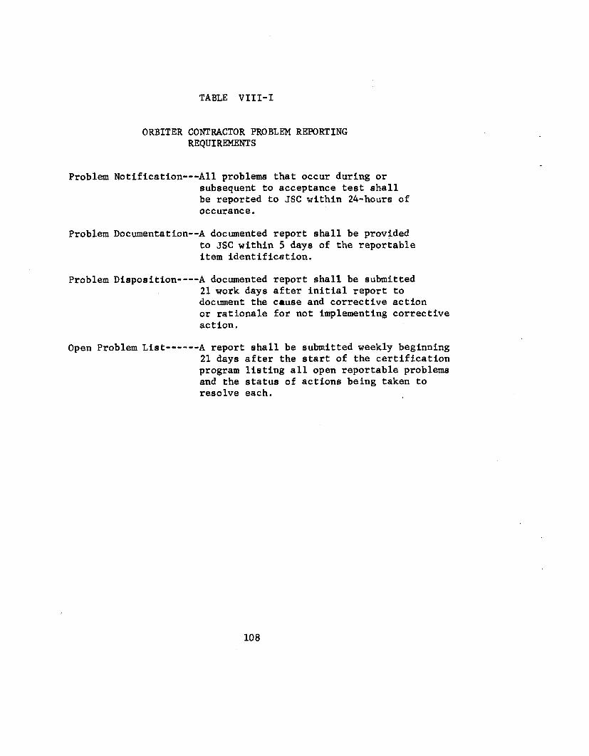
TABLE VIII-I
ORBITER CONTRACTOR PROBLEM REPORTING REQUIREMENTS
Problem Notification---All problems that occur during or subsequent to acceptance test shall be reported to JSC within 24-hours of occurance.
Problem Documentation--A documented report shall be provided to JSC within 5 days of the reportable item identificstion.
Problem Disposition----A documented report shall be submitted 21work days after initial report to document the cause and corrective action or rationale for not implementing corrective action.
Open Problem List------ A report shall be submitted weekly beginning 21 days after the start of the certification program listing all open reportable problems and the status of actions being taken to resolve each.
108

v)
e
U
-
$5 z 0
4
109

FIGURE V I I I - 2
SPACE SHUTTLE INTEGRATION PROBLEM REPORTING AND CORRECTIVE ACTION SYSTEM
OPENED RESOLVED . I a
CONTRACTOR CONTRACTOR EVALUATION/ 4 RECOMMENDS
PROBLEM i
I I ANALYSIS CORRECTIVE
ACTION
'~~ I b
ELEMENT +. PROJECT
OFFICE
T
i CONCURRENCE NOTIFIES 8 .
I I JSC PROBLEM I I' . I JSC I
8
I CONTROL SYSTEM . I
a
I ENG., - SR&QA,
i NOTIFIES
I JSC PROBLEM I
. I I JSC I I
CONTROL SYSTEM . I'
CONCURRENCE
I l i
I I NOTIFICATION I O F SYSTEMS
LEVEL PROBLEMS I
CONCURRENCE I I
1 SPACE SHUTTLE PROGRAM OFFICE

I / t l t 76 JSC SHUTTLE OPEN PRotnEn LIST-TECHNICAL ISSUES PACE 1 I DC ORBITER - DISPLAYS AND CONTROLS
(OBLEH I O f N 1 I F IC A 1 I OM I SSH/TMI FG2/A. J-FARKAS ACTIUI I ASSIGHEEI D.OUSTON
LEVEL 1 YPF VFHICLE ON CAUSE FAIL HOD€ lES l /OPER PREVAIL. COND. LOCATION OCCUWREO DATE REPORT NUHBER L L f H F l l I WSAT CONO i o i DES- * OUlPUT FALSE CKO FUNGI I ONAL R I P L H 0 5 / 2 0 / 7 6 A2766-01
AR D bl AF! E I ll EN T I F I C A T I ONI PART NUHefR PART NINE HFG SERIAL /LO l DATE/TIME UPDATED REFERENCE m9/t i /76 i3sas3 IFPIT ARTICLT VO 7 0-0 0 00 02- 1 0 1 ORBIIER GENFRAL RIDNV o i a i
t~OtlCOtIFOd 1ING ARTICLE VB 70-00 8002-101 o R e x r E R GENERAL RIONY 0101 HEX1 HIGHEv ASSEMBLY RESOLUTION DATE UORK UNIT CODE
MISSION NUHeFR AL 1 VEHICLF NUHPEH 1 0 1 C P I l - SlAIUS 3- FXPL
ROBLEH F F F E C l I V I T V I @ 9/17 / 76
RORLEH nL SCR TP 1 ION I DURING THE O V - 1 C l F I P S l POUER APPLICATION TO I N S l A L L E D FLT COMPONENTS* USING FLIGHT YIRE HARMESSES AND OURINC THE FIRST TEST
6SOSZ-SZOBlbl.33 FOQ f U F L CELL POWER PLANf NO. 2, HZ RFACTANT SUPPLY VALVE IHCZIS-0429-0200) ON COCKPIT 0 AN0 C PANEL RZ MOUE0 HALFUAY R f T U E E H G Y A V I N 0 R A W E R POLE INDICATION WtlEN THE VALVE WAS COHHANOEU FROM OPEN TO CLOSE RY SYITCH S-29~HE452-0102-6ZbS. THE
8NALYSISI A T O T A L O f 14 UII lOFF CYCLES. AFTER THE F I P S I CYCLf THE ANOHALV OISdPPEAREO AN0 010 NOT RFCUR. 2-NONE. S-THE ‘ANOMALY OCCUPRED OLSXNG r t E O V L C l F I D S I POYEP APPLICAI ION TO INSTALLED FLIGHT CONPONEHTS AND USING FLIGHT WIRE HARNFSSES. 4-ANALYSIS INOICA lEO THE HOST PROflARLf CAUSF IS INTERNAL STICKING OF THE INDICATORS MOVEMENT. CAUSE0 BY A FOREIGN PARTICLE* WHICH AFTER ONF CYCLE HAS DISPLACED P t R H I l T l N G TliF INDICAIOP T O FUNCTION NORMALLY. 5-LAST 1 E S l IS THE NORMAL PRE-FLIGHT SYSTE(I READINESS CHECKS. 6-ANOMALY C A M BE
CONOUCTFD PER ICP n~0~20-45oi-101. POWER REACTANT SUPPLY AND OIST. AIW POWER GEM. FUNCT. c/o THE ~ C S S Z - O Z Z Z - O O ~ ~ EVCHT o m / SH
FVEYI 1rin. SHOULD nE FULL BAReER POLE. i-rw SWITCH s29 W A S suesEauEhrt.r CYCLED i o OPEN AND CLOSE THE VALVE
w D6TFI;lEn ON T l i E GROUNI) V I A PCM DOYNLINK LND CQEW CAN ORSCftVE THE 0 2 REACTANT 7 lESOLUl loll1
VALVk I tNl ICATl lR 4COHPAPISONI 10 EVALUAIE THE CONDITION XN REAL TIME WHEN COHMAND I S SENT. I - H I S S I O N EFFECI-NONE. 1YERE ARE HO SLFETY tlL74ROF TNVOLVED U I T H A RECURRENCE OF THIS LNOHALY. I - A FAILURE OF THE INDICATOR WILL NO1 EFFECT THE OPERAIION OF THC FUEL CFLL POHCP PLANT. IT IS POSSIBLE THIT I H E FUEL CELL DAHAGE COULD OCCUR KF REACTANT I S SUPPLIED I C ON€ INLET ONLY1 HOUEVER. THIS WOULI) QEOUIPE A l l AClUAL V ILVE FAILURE I N ADDITION T O THIS ANOMALY (SECOND FAILUREJ THE CREY CAN EVALUITE THE CONDXTIOII REAL T IHE YNEN 1HE COHHIINU IS SFNT BV CWPARINC THE 0 2 AND fH€ HZ REACTAN1 VALVE INDICATIONo 9-NOM. IO-THE - 0 0 1 6 INDICATOR IS FOR O V l O l A L T USE ONLY.
MI I Q N ASSIGtlFE I C.FLE1 CHER S S M / l M l EGZ/&.J.FCRKAS PRORLEH l U f NTIF ICLT ION8
LEVFL TYPE VFHICLE ON CAUSE F A I L MODE TESl/OPER PRtVAIL. CONO. LOCATION OCCURRED OAT€ REPORT N?)HBER A(r543-01 06 /11 /76 ELFMCNI FA ILURt HFG- - F A I L S OPEN PAL L I F E EOISEL
HAPDUAPE IUEN 1 I F ICATIONt PART NUMBFR PART NAHE XFC SERIAL/LOl DATEITIME UPDATED RLFERC NCE VFSI A f t l I C L E ~ c ~ ~ ~ - o ~ s ~ - o o o ~ SUITCH TtIuneYHFEL os EOISEL 0001 0 9 / 0 9 / 1 6 1 6 5 4 1 6 HONCOHFllRHI #G APT ICLE HC 452-9 1 S 4 - 0 # 0 1 SYttCH fHUHRWHEEL OS EOfSZL 0001 N E Y l HIGHER ASSEHRLY RESOLUTION DATE now UNIT COUE
H l S S X O N IWYRFR A L r VFHICLE WYflER i a i i m i CRIT - SlATUS 3- OPEH I- OP€N
PROBCEH CFFECTTVITVI Esr 09/24/16
PRODLFH u w m p r I o i i * UIIhSLC TO CHTCK SYI ICM ELCCIPICALLY. UNARLE T O HAkF CONTLCT Y I T M SWITCH INTEPNALLY.
REFLPKS I
FIGURE V I I I - 3

s I GN I FI clvu- PROBLEMS DATE -tu f:
9 / 2 9 / 7 6 PRm REPOR iESPONSIB1 LITY: LIBSYSTEM MGR. w. SIMI.1ONs iR&QA ASSIGNEEnVEY
' A5098 . EST. R E S O L U T I O N 11,12,76
PART NUMBtR:
MC 325-0004-0012 '
CRIT ICAL ITZ .'2
'RO BLEM : DURING LOT ACCEPTANCE TEST FIRiNGS CF 0F.iE-WAY TRANSFER, ONE UNIT FAILED TO F IRE HIGH ORDER A i AXBIENT CONDITIONS (EXPLOSIVE M I X DEFLAGRATED OR BURNED INSTEAD OF DETONATED). AFTER A REBUILD DUE TO SIMILAR PqOBLEMS WHICH OCCURRED 6/9/76. I N FAILURE ANALYSISIBUT PRIMER PpCKET . ACT I ON.
THIS LOT WAS BEING RETESTED ORIGINAL- PROBLEM WAS NOT DUPLICATED
W A S REDESIGNED AND PRIMERS WERE 100% SCREENED AS A CORRECTIVE
EFFECIIVITY: ov-101 & ov-102
. I
S C H E D U L E IMPACT: - . SERIOUS IMPACT ON HARDWARE NEED DATE OF 10/25/76 FOR I CREW ESCAPE SYSTEM BREADBOARD TESTS AT ROCKWELL AND SLEC
STATUS: .d SEVERAL DESIGN INTERFACES HAVE BEEN CHANGED: (SEE ATTACHED DRAWING)
A PRIMER CHAfjGED TO SAME TYPE USED ON TIME DELAYS - M42C1 INSTEAD OF M42C2 . I
B 1 PRIMER FLASH HOLE DIAM. DECREASED C) D)
L / D COLUMN RATIO OF LEAD AZIDE REVISE0 TO 2.0 FROM 1.0 AND COLUMN LOAD PRESSURE REDUCED. HNS "PANCAKE" FOLLOWING HNS OUTPUT CHARGE INCREASED TO 0.09 IN. FROM 0.03 IN .
0 SECOND SOURCE VENWR UNDER CONTRACT - QUAL DATA FOR F-14 DEVICE UAS REVIEI.IE0 10/12/76 BY JSC & ROCKlJELL AND CONSIDERED ACCEPTABLE WITH EXCEPTION OF TWO DESIGN PARAMETERS WHICH WILL REQUIRE WAIVERS (SEE ACTION REOUIRED). R I HAS PURCHASED PARTS FOR BREADBOARD TESTS.
ACTION REQUIRED: b AT EXISTING VENDOR: REDESIGN DEVICE AS DESCRIBED ABOVE AND PERFORM LAT.
(ROCKWELL TO CONTINUE PARALLEL EFFORT UNTIL F-14 WAIVER APPROVAL I S IMMINENT).
R I TO REVIEW AND FORMALLY APPROVE DOCUMENTATION INCLUDING ATP & QTP, C) SUBMIT WAIVERS FOR NON-GFE HNS AND NON-APPROVED
fl AT SECOND SOURCE VENDOR: A) 6 ) REVISE-SPEC. TO REFLECT NEW CONFIGURATION, _ _ - * ... . !* . - (JSC 08060) PRIMERS U T I L I Z E D I N F-14 PART. . .. .. .
STATUS: AS OF 10/25/76.. N N : f7 OPEN: a CLOSED:
FIGURE VIII-4a

,
. . . I
0.003, 1100-0 FOIL 1)ISC 78 EIC HXS I 0.10 D I A . IN., 0.17 DIA COXSOLIDATED AT 32,000 PSI
M42C2 ?RI I IER
0.004, 304 CRES D I S C 0.125 f. 0.005 DIA. 0.03 COLUMN, HNS I, AT 32,000 PSI
47 MG LEAD A Z I D E 0.10 D I A . x 0.10 LONG 1 (L/D - 1.0) CONSOLIDATED 32,000 PSI, 1 INCRDIENT
PRESENT OPIE-WAY TRANSEER F I T T S G DESIGN
P F w
0.003, 1100-0 FOIL D I S C UNCHANGED HNS I CHARGE
-.
UNCW’GED D I S C
OLLm HNS I, AT FIGURE VIII-4b
.
,. OUT
._ .

TO FERSONNEL DUE TO
LOSS OR INJURY LOSS OR I N J U W TO PERSONNEL TO PERSONNEL
DUE TO DUE TO CAMIM/ACTIVE TESTS FREE RlGM TESTS
I
LOSS 0 5 INJURY TO PERSONNEL DUE TO FEW
VERIFICATION TESTS
LOSS OR INJURY TO PERSONNEL
DUE TO G W L M D OPERATIONS
IMPACT 0 IMPACT 0 FIRE 0 FIRE 0 ELECTRICAL SHOCK 0 CONTAMINATION CONTAMINATION
TOXKITY EXPLOSION
0 ELECTRICAL SHOCK
0 TOXlClTY
A
IMPACT FIRE
0 ELECTRICAL SHOCK 0 EXPLOSION 0 CONTAMINATION 0 TOXICITY
LOSS OR INJURY TO PERSONNEL
DUE TO CAMIWINERT TESTS
TO PERSONNEL DUE TO N G M
0 IMPACT 0 FIRE
EXPLOSION 0 CONTAMINATION 0 TOXICITY o PHYSIOLOGICAL VIBUTION/NOISE
THERMAL
+ \ -OR* GATE -'PERFOI(MS THE LOGIC FUNCTION THAT REWIRES ANY ONE OF THE GATE INPUTS TO OCCUR TO PLUIZE THE OUTPUT EVENT
IMPACT 0 IMPACT IMPACT FIRE FIRE 0 FIRE ELECTRICAL SHOCK 0 ELECTRICAL SHOCK EXPLOSION
0 EXPLOSION 0 EXPLOSION t C N i A i N A T l O N 0 CONTAMINATION 0 CONTAhVNATION 0 TOXICITY 0 TOXICIN 0 TOXlCllY PhYSlOLOGlCAL 0 PHYSIOLOGICAL PHYSIOLOGICAL 0 VIBRAIION/NOISE 0 VlBRATION/NOISE VlaRATION/NOISE THERMAL 0 THERMAL 0 THERMAL
Figure VIII-5a ALT Yission Operations F a u l t Tree
0 CONTAMfNATlON SHOCK
'OR' SATE - PERFOmS THE LOGIC FUNCTION "IT REQUIRES ANY ONE OF THE GATE INPUTS TO OCCUR TO REALIZE THE OLTWT EVENT
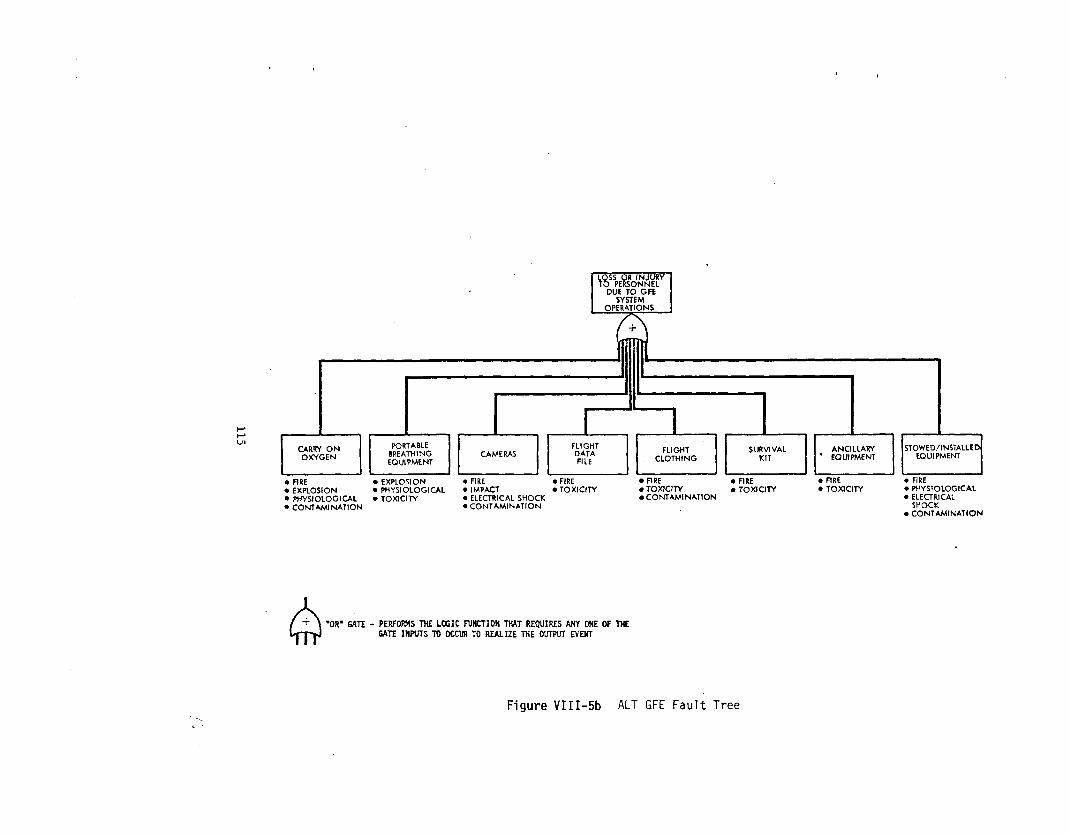
Figure VIII-5b ALT GFE F a u l t Tree
INJURY TO PERSONNEL
TO ORS!TER SYSTEM
LANDING/ STRUCTURES DECELERATION rz<F&
SUBSYSTEM
AEROFLIGHT I CONTROL SUBSYSTEM
CREW ESCAPE PYROTECHNIC GENElUL COMMAND PURPOSE
SYSTEM SYSTEM COMplJTER
*ELECTRICAL VIBRATION/ SHOCK NOISE
PROCESSING DATA AND SOFWAff SUBSYSTEM
SUaSYSTEM I PHYSIOLOGICAL FIRE FIRE *.FIRE IMPACT TOXICITY EXPLOSION EXPLOSION
IMPACT TOXICITY TOXICITY PHYSIOLOGICAL THERMAL THERMAL CONTAMINA- PHYSIOLOGICAL IMPACT TlON IMPACT
SYSTEM SUBSYSiEM TATION
FIRE FIRE FIRE FIRE RADIATION RADIATION RADIATION 0 RADIATION ELECTRICAL THERMAL THERMAL THERMAL
IMPACT SHOCK SHOCK SH3CK OUlQuT 0 IMPACT IMPACT IMPACT
SHOCK ELECTRICAL ELECTRICAL ELECTRICAL
I
‘OR’ GATE - P E R F W THE LffiIC “CTIO# TWIT R E W I R E S ANY ONE OF THE GATE INPUTS TO OCCUR TO REALIZE THE OUTPUT NENT Q
FIRE FIRE . FIRE RADIATION RADIATION RADIATION ELECTRICAL 0 ELECTRICAL ELEClRlCAL SHOCK SHOCK SHOCK IMPACT IMPACT IMPACT EXPLOSION
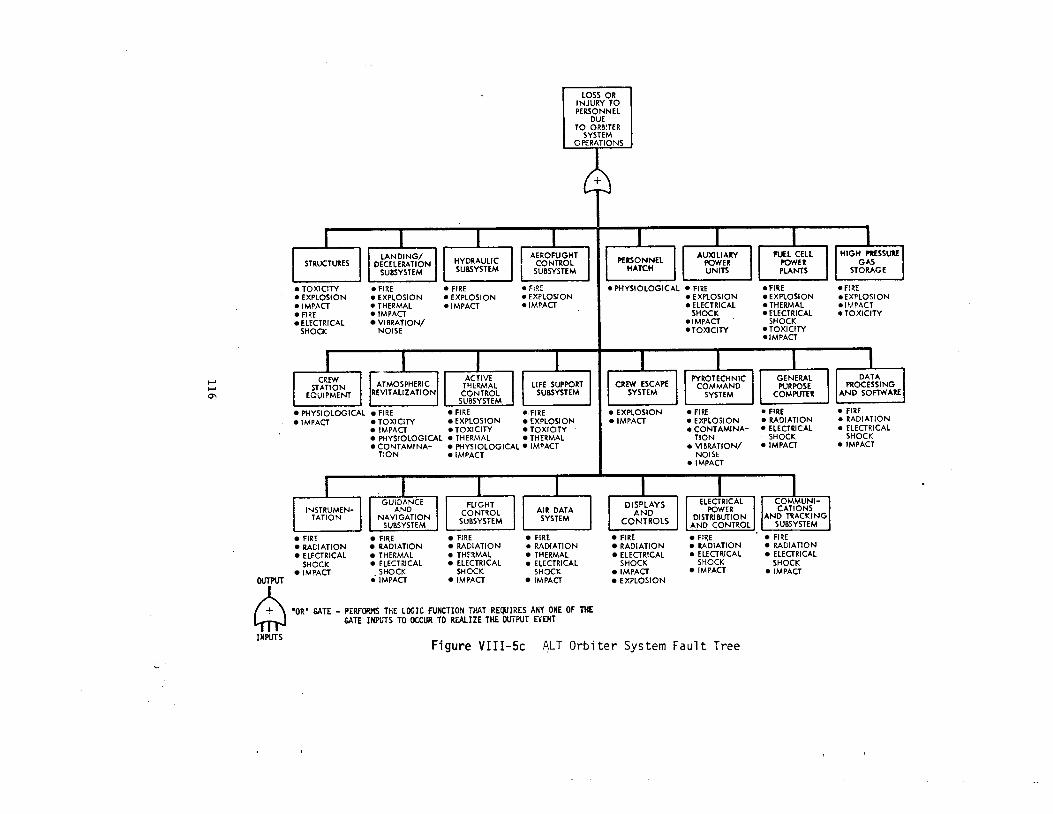
INWTS Figure VIII-5c ALT Orbiter System Fau l t Tree
4
LOSS OR INJURY TO PERSONNEL
DUE TO 747
LOSS OR INJURY TO PERSONNEL TO PERSONNEL
DUE TO DUE TO CARRIER AlRCRAFl am ESCAPE MODIFICATIONS HARWARE
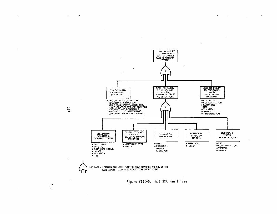
Figure VIII-5d ALT SCA Fau l t Tree

LOSS OR INJURY LOSS OR INJURY TO PERSONNEL TO PERSONNEL
DUE TO DUE TO ORBITER SYSTEM GFE SYSTEM
OPERATIONS OPERATIONS
I LOSS oa INJURY TO PERSONNEL
DUE TO
LOSS OR INJUw TO PERSONNEL
DUE TO
OPERATIONS GSE SYSTEM SHUTFLE CAW(IER AlRCRAFl SYSTEM I
OPERATIONS I
"OR" U T E - PERFORMS THE LOGIC NNCTION THAT REQUIRES ANY ONE OF THE Q GATE INPUTS TO OCCUR TO R W I Z E THE OUTPUT EVENT
Figure VIII-5e ALT System Operations Fault Tree

W W L
I
W
5 a 0
119
IX. CONFIGURATION MANAGEMENT AND INTERFACE CONTROL
A . Introduction
The general significance of the configuration management system
for the Panel is that it assures that the program knows what is in
fact being designed, built and tested so that the real risks are iden-
tified and dealt with.
every level of a complex program and thus is an inherant technical and
administrative activity of any NASA and DOD program. The system does
not force the use of unnecessary paper or levels of management but
does require that there be sufficient documentation to assure that
management, design and user organizations have timely information
necessary for effective decision making, risk assessment and program
control.
It forces a necessary degree of discipline on
Because of the significance of this system the Panel made it a
point to emphasize in its last Annual Report that the Pane1,had not
yet completed consideration of other important system integration
issues such as configuration management, interface control and inter-
action between Shuttle system elements but that it intended to do so
as soon as feasible in terms of its large workload. This section re-
ports on the Panel's review to meet this commitment before the ALT
flights. In fact the Panel felt that an examination and assessment
of the Configuration Management System as it is both documented and
implemented is one of the basic steps in assessing the adequacy of the
ALT management system in establishing a real basis for confidence in
'achieving mission success and flight safety.
120
The Panel in designing its review of this area considered the
demands the system must successfully meet.
1. The system must support the programs' ability to pro-
duce hardware and software that is capable of being qualified and cer-
tified for flight, and then can be maintained, replaced, or modified
as information on operational characteristics becomes available through
flight tests.
2. The Shuttle Program is ae diverse as its predecessors,
the Apo'Llo Program, Skylab, and the Apollo Soyuz Test Project. It has
numerous prime contractors and technical support spread all over the
country and there is bound to be some degree of non-standardization as
well as coordination problems. These will be difficult to overcome
even with the dedicated people known to be working these areas.
3 . Element and integrated system aggregate risk assess-
ments must be based on knowledge of the "as-built" and "as-tested"
hardware and software.
also be based on such known configurations.
Accepted risks and their justification must
4 . Development, qualification, and acceptance testing
schedules are extremely tight and overlap with manufacture and instal-
lation requirements. Therefore, hardware and software mismatches and
materiel problems, resulting from inadequate configuration management,
can lead to schedule and cost impacts. Inadequacies therefore must
be minimized.
Therefore, the Panel focused on the following elements of the
configuration management system:
1. The system as documented.
121

a. Level I, 11, 111 and IV requirements and procedures.
b. Organizational responsibilities and intercenter relationships.
c. Relationship with Master Verification Plan.
d. Configuration accounting system and repositories.
2. The system as implemented.
a. Degree of configuration control being applied to each element to determine current baselines.
b. The processing of actual hardware/software changes from inception to completion.
c. Documentation to relate the "as-designed" to the "as-built" to the "as-tested" hardware/sof tware.
d. Activities of the Space Shuttle Program Configur- ation Management Panel (SSPD # 6 ) , the Level I, I1 and 111 Program Requirements Control Boards (PRCB's) and the systems engineering support provided to these activities.
e. Use of Configuration Management products to support the Space Shuttle Review system, e.g., CDR'S, DCR's, and Flight Readiness Reviews.
f. The relationship between logistics (maintenance, spares, etc.) and the Configuration Management System.
g. Relationship between Safety, Reliability Quality Control and the Configuration Management System.
Since the following fundamental terms are used in this section
of the report, they are defined to avoid any confusion.
1. Configuration Management System. The total system to
(a) identify and document the functional and physical characteristics
of all program hardware and software and the major test operations on
them, and (b) control the processing of changes to the hardware, soft-
ware, test functional and physical characteristics.
1 2 2

2. Configuration Management. The s e t of po l i c i e s and pro-
cedures t o implement the system. These must cover requirements, iden-
t i f i c a t i o n , control , accounting and ve r i f i ca t ion .
3 . In te r face Control o r Management. The spec i f i c s e t of
po l i c i e s and procedures t o govern s i t u a t i o n s where one element, such
as the Orbi ter , i s dependent on another, such a s the External Tank.
The in t e r f ace o r two-dimensional plane between elements must be de-
signed and manufactured so t h a t when the elements come together they
match i n every d e t a i l physical ly and operat ional ly . The cont ro l of
the i n t e r n a l i n t e r f aces such as between the e l e c t r i c a l generating and
d i s t r i b u t i o n system and the f l i g h t cont ro l system within the Orbi ter
i s within a s ingle NASA Center and s ingle p r ime contractor . On the
o ther hand In te r face Control i s between elements which means between
prime contractors and NASA Centers. Thus a change considered by the
management of one element must be considered i n terms of i t s impact
on the o ther element and t h e i r integrated operation.
The observations t h a t follow a r e based on the program responses to
s p e c i f i c questions, d i r e c t quotes from b r i e f ing mater ia l and notes
made during discussions.
B. Observations
1. General Information.
The Space Shut t le program has streamlined the configur-
a t i o n management methodology which evolved through Apollo, Skylab and
Apollo Soyuz. Paperwork has been reduced, e f f ic iency increased and
changes made t o some bas ic operat ing pr inc ip les .
123
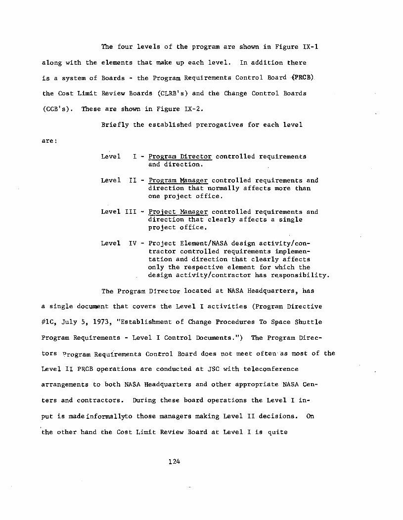
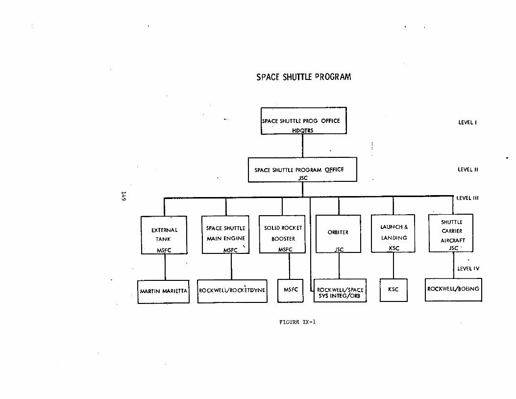
The four levels of the program are shown in Figure IX-1
along with the elements that make up each level. In addition there
is a system of Boards - the Program Requirements Control Board @RCB) the Cost Limit Review Boards (CLRB's) and the Change Control Boards
(CCB's). These are shown in Figure IX-2.
Briefly the established prerogatives for each level
are :
a sing1
Level I - Program Director controlled requirements and direction.
Level I1 - Propram Manager controlled requirements and direction that normally affects more than one project office.
Level I11 - Project Manager controlled requirements and direction that clearly affects a single project office.
Level IV - Project Element/NASA design activity/con- tractor controlled requirements implemen- tation and direction that clearly affects only the respective element for which the design activity/contractor has responsibility.
The Program Director located at NASA Headquarters, has
document that covers the Level I activities (Program Directive
#lC, July 5, 1973, "Establishment of Change Procedures To Space Shuttle
Program Requirements - Level I Control Documents.") The Program Direc-
tors Drogram Requirements Control Board doe$ not meet often.as most of the
Level I1 PRCB operations are conducted at JSC with teleconference
arrangements to both NASA Headquarters and other appropriate NASA Cen-
ters and contractors. During these board operations the Level I in-
put is madeinformallyto those managers making Level I1 decisions.
the other hand the Cost Limit Review Board at Level I is quite
On
124

ac t ive , meeting on the average of once eachmonth t o make decis ions -
t ransmit ted t o i t via Level I1 o r determined a s necessary a t Level I
i t s e l f . There i s no program d i r ec t ive es tab l i sh ing t h i s CLRB and
def ining i t s operation; but , s ince i t has been i n ac t ion fo r some
years , i t i s not expected t o require such documentation a t t h i s l a t e
s tage of the program. The Program Director i n Washington uses the CLRB
t o cont ro l cos t s and the PRCB t o control "reserves", %.e. , computer memory
reserve capacity o r e l e c t r i c a l power generation capacity reserves .
The workload a t Level I1 requires the serv ices of three
C iv i l Service persons and nine R I contractor support persons. The
nature of such work a l s o requi res the part-t ime use of technical per-
sonnel from other NASA d iv i s ions a t JSC.
In addi t ion there a r e Level111 and I V systems a t the
pro jec t l e v e l t h a t must function e f f ec t ive ly t o assure an adequate
t o t a l system fo r decis ions made here t h a t a r e not reviewed a t higher
management l eve l s .
In te r face cont ro ls a r e under the purview of the Systems
In tegra t ion Office a t Level I1 and t h e i r mode of cont ro l and use follow
tha t fo r normal Level I1 operat ions.
The operat ion of t h i s system i s discussed i n more de-
t a i l i n the following sec t ions .
2 . Configuration Management Requirements
The basic philosophy used i n developing the requirements
i s :
(Centers, and represents a carefu l appl ica t ion of the experience gained
i n previous NASA, mil i t a ry , and commercial space and a i r c r a f t programs."
"This document has been j o i n t l y developed by the Manned Spacefl ight
125

To be effective from the standpoint of producing hardware and soft-
ware in a timely, orderly manner within the cost constraints, con-
figuration control by NASA is established only "when and where it is
necessary and when it will tend to stabilize program efforts. Caution
must be taken to prevent premature control and control at too low a
level of detail."
These requirements are set forth in JSC 07700, Volume
IV, "Configuration Management Requirements," baselined March 2, 1973
and a Revision A issued in April 1974. Changes are made as required
by reorganizations, personnel changes or to meet the demands of the
ongoing Shuttle program. Through November 1976 sixteen changes to
this document have been processed and incorporated.
The additional documentation used by the program and
examined by the Panel are as follows:
a. "Level I1 Baseline Description and Status Re-
port," JSC 08102, published monthly and contains about 70 pages of
computer printout.
b. "Space Shuttle Orbiter/System Integration Con-
tractor Configuration Management Plan," SD73-SH-O22A, June 23, 1975
issued by Rockwe11 International, Space Division.
c. "Shuttle Carrier Aircraft Project, Configuration
Management Manual," JSC 08140, January 13, 1975.
d. "Space Shuttle Program Configuration Management
Panel," SSPM Directive No. 6A, July 3, 1974. This directive established
phis Panel as a mechanism for reviewing, assessing, advising and guiding
the proper integration of configuration management activities across
126

the program.
3 . Configuration Identification.
Identification refers to the manner and documentation
for describing in detail all program hardware and software. Require-
ments and configuration are identified in detail for the practical
purpose of producing hardware and software which meets or exceeds
specified requirements and is a baseline used for control and account-
ing of changes as they occur.
The baseline at each level of the program requires those
types of data shown in Table IX-I. Note that the interfaces are taken
into account in these listings.
An integral part of the identification process is the
assurance of hardware traceability. Traceability is the identification
technique of correlating historical records to each item. These re-
cords are valuable in resolving hardware problems, understanding age-
life characteristics and helping to assure reliable and safe flight
and ground equipment.
To illustrate the set of documentation required for a
project (Level 111) here is the documentation required for the Shuttle
Carrier Aircraft:
a. All the applicable requirements of the NASA Level I
and I1 baselines.
b. Specification MJ510-0001-1, "Shuttle Carrier Air-
craft Contract End Item Specification - Design and Performance Re- quirements." Baselined by the Shuttle Carrier Aircraft Project Manager
on April 9, 1976.
127

c. Specification JSC-08943, "Flight Test Requirements - Volume I - Shuttle Carrier Aircraft." Baselined by Orbiter and SCA
Projects on December 12, 1975.
Configuration Identification includes the Interface Con-
trol Documents (ICD'S) used to control interfaces between two or more
participating contractors and government agencies. In effect the ICD's
augment the contractural specifications by documenting the requirements
and agreements between interfacing contractors and/or NASA.
tent of these ICD'S can be seen on Table IX-I1 which is from ICD 412-17001,
"Orbiter/Carrier Aircraft, Ferry and ALT. This particular ICD is unique
in that two configurations are presented, both of which involve the
Orbiter and the 747 aircraft, that is, ferry flights and the ALT.
The con-
Identification also includes drawings - a drawing tree for both flight and ground systems (this is in effect a directory of
drawings), engineering drawings and a part number control system.
4 . Configuration Control.
The baseline as established at any given time must be
protected from inadvertant and/or unauthorized changes. The baseline
is normally a product of such configuration reviews as the Preliminary
Design Review (PDR) and the Critical Design Review (CDR). In addition
to these traditional reviews, the Space Shuttle program has added
a series of incremental design reviews. For instance there is a system
of reviews to consider the design in light of prior testing and before
proceeding to the next step of the program. These are called Customer
Pcceptance Readiness Reviews (CARR's) or Configuration Inspections (CI's)
Thus there was a Phase I configuration inspection in the Spring of
128
1976 which reviewed the design in light of testing and whether it was
ready to proceed through individual subsystem testing. Then a Phase I1
review was held in October 1976 to consider what had been learned about
the design from this individual subsystem testing. A Phase I11 review
in late January 1977 considered the proof of design in the light
of integrated testing. The Phase I11 review authorizes the program to
proceed with final testing and delivery of the vehicle.
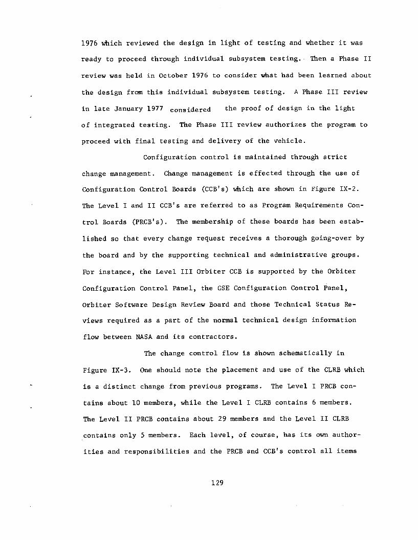
Configuration control is maintained through strict
change management. Change management is effected through the use of
Configuration Control Boards (CCB's) which are shown in Figure IX-2.
The Level I and I1 CCB's are referred to as Program Requirements Con-
trol Boards (PRCB's). The membership of these boards has been estab-
lished so that every change request receives a thorough going-over by
the board and by the supporting technical and administrative groups.
For instance, the Level I11 Orbiter CCB is supported by the Orbiter
Configuration Control Panel, the GSE Configuration Control Panel , Orbiter Software Design Review Board and those Technical Status Re-
views required as a part of the normal technical design information
flow between NASA and its contractors.
The change control flow is shown schematically in
Figure IX-3.
is a distinct change from previous programs. The Level I PRCB con-
tains about 10 members, while the Level I CLRB contains 6 members.
The Level I1 PRCB contains about 29 members and the Level I1 CLRB
contains only 5 members. Each level, of course, has its own author-
ities and responsibilities and the PRCB and CCB's control all items
One should note the placement and use of the CLRB which
129
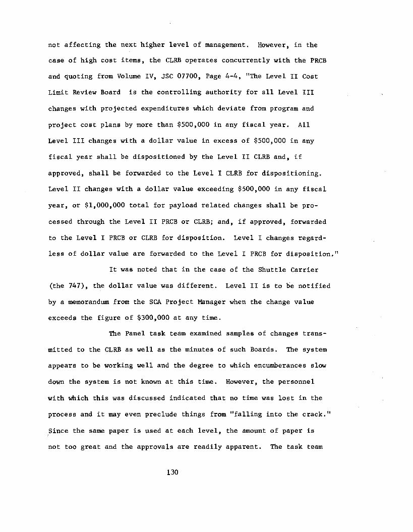
not a f f ec t ing the next higher l eve l of management.
case of high cos t items, the CLRB operates concurrently with the PRCB
and quoting from Volume I V , JSC 07700, Page 4 - 4 , "The Level I1 Cost
L i m i t Review Board i s the cont ro l l ing au tho r i ty f o r a l l Level I11
However, i n the
changes with projected expenditures which deviate from program and
pro jec t cos t plans by more than $500,000 i n any f i s c a l year.
Level I11 changes with a d o l l a r value i n excess of $500,000 i n any
f i s c a l year s h a l l be disposi t ioned by the Level I1 CLRB and, i f
approved, s h a l l be forwarded t o the Level I CLRB for disposi t ioning.
Level I1 changes with a d o l l a r value exceeding $500,000 i n any f i s c a l
year, o r $1,000,000 t o t a l fo r payload r e l a t ed changes s h a l l be pro-
cessed through the Level I1 PRCB o r CLRB; and, i f approved, forwarded
to the Level I PRCB o r CLRB fo r d i spos i t ion . Level I changes regard-
less of d o l l a r value are forwarded t o the Level I PRCB fo r d i spos i t i on , "
A l l
It w a s noted tha t i n the case of the Shut t le Carr ier
( the 747), the d o l l a r value was d i f f e r e n t .
by a memorandum from the SCA Project Manager when the change value
exceeds the f igure of $300,000 a t any t i m e .
Level I1 i s t o he n o t i f i e d
The Panel task t e a m examined samples of changes t rans-
mitted t o the CLRB a s w e l l as the minutes of such Boards. The system
appears t o be working w e l l and the degree t o which encumberances slow
down the system i s not known a t t h i s time. However, the personnel
with which t h i s was discussed indicated t h a t no time w a s l o s t i n the
process and i t may even preclude things from " fa l l i ng i n t o the crack."
Since the same paper i s used a t each l eve l , the amount of paper i s
not too grea t and the approvals a r e r ead i ly apparent. The task team
130

examined a number of PRCB Minutes and Directives to ascertain the
depth of material covered, action items and distribution. A sample
"change package" was selected (actually several were examined) at
random to provide an example of the system and how it worked in real
life. The change selected was identified by No. RO1911, "Gimbal
Actuators - 3 port versus 4 port." It affected the Orbiter and the
Space Shuttle Main Engine and the Solid Rocket Booster which use such
actuators.
JSC and superceded a previous change request. The paperwork indi-
cated that this was a mandatory change costing as much as four million
dollars during a four year period.
ized the forwarding of this change to Level I1 on August 5, 1975 since
the cost was over the $500K limit. The Level I1 CLRB approved the for-
warding of this change to Level I on August 29, 1975, and Level I
approval was given on October 16, 1975. The change was, at the same
time, undergoing assessment and impact analyses by the cognizant
technical organizations so that the change was fully evaluated in
terms of cost, schedule, engineering and safety, reliability and
quality assurance requirements. It was then reviewed and approved
by the Level I1 PRCB because it affects more than one project as well
as being a high-cost item. The directive to implement the change was
issued on October 21, 1975 with specific actions to be accomplished
by the end of November 1975. At that time an addendum to the original
directive was prepared and signed out February 28, 1976. The close
The change was originated in the engineering division at
Level 111 Orbiter CCB approved and author-
out paper shows the actions taken by the appropriate
offices and contractors. Direction was given to the
MSFC project
contractor and
131

NASA internal documentation was modified accordingly.
views assure that the change was made.
Project re-
A special effort was made to review the configuration control
as app:ied to the most significant items or elements of the Approach
and Landing Test Project. These elements included the test vehicles
and supporting GSE, support resources and the operating plans and pro-
cedures. Table IX-I11 succinctly shows the item, control mechanism
and the accounting. The activities are divided between JSC, DFRC,
KSC, and Rockwell International, Space Division.
4 . Configuration Accounting.
The accounting portion of the configuration management
system provides visibility to every level of management and working
organizations as to the status of the baseline, changes to the base-
line and actual hardware configurations and software posture.
addition, almost all of the myriad groups in the Space Shuttle program
require such data for safety analyses and assessment, reliability and
quality assurance assessment, weights, status reporting, logistics,
mission planning, etc.
In
Configuration accounting activities are divided into
two areas: (a) baseline accounting and reporting, and (b) config-
uration verification and accounting. Item (b) will be discussed
separately. Each NASA Center and their contractors utilize different
systems to provide the required data. These systems were developed
by each organization from their prior programs.
pecessary data is provided there is no need for uniformity in the
system. Because of the focus on ALT and Orbiter, this discussion will
Since the
132

center on Level I1 at JSC and their support by Rockwell, and the
Level I11 at JSC covering the Orbiter and the 747.
The current system at Program Level I1 and Orbiter
Level I11 is called the "Baseline Accounting and Reporting System"
(BARS). It uses the Rockwell International/Space Division computer
system and software. The BARS system has the capability of record-
ing, integrating, statusing, and reporting data for the NASA Levels
I, 11, and 111 baseline requirements. Rockwell, as the System Con-
tractor, has personnel located at JSC, MSFC and KSC to perform the re-
quired duties. NASA and other element contractors submit on a regular
basis to the System Contractor such information as:
a.
b.
C.
d.
e.
f.
g.
h.
i.
1.
Level I1 Change Requests
Level I1 Documentation Changes
Engineering Change Proposals (all projects, Level
NASA CCB and PRCB Directives
Level I1 Change Evaluations
Listings of ICD'S and specifications, and updates
NASA Technical Directives (all projects)
Contract Change Authorizations (all projects)
Other Closeout Documentation (Level 11, I11 and All Projects)
CCB Agenda and Minutes on All Projects
A good deal of this data from the NASA Centers is put into the system
through a remote terminal setup at JSC, KSC and NSFC which links them
to the Downey Computer Unit.
The output of this BARS setup can be formattedin any form required
111)
133

by management or the technical organizations. There are, of course,
many specifically identified reports produced because they fit a con-
tinuing real need by user groups.
listing noted before, Level I1 Change Status Reports each week, PRCB
Level I1 actions status reports each week, and so on.
For example, the baseline documents
5. Configuration Verification
Configuration verification is accomplished by Rockwell
International Space Division in support of Level I1 and I11 program
management. They use the data from the individual Prime Contractors
as well as the Configuration Accounting System and manufacturing and
quality control reporting systems. Thus they are able to provide:
a. Requirements verification used at all major re-
views of the hardware and software.
b. Verification of the original baseline configuration
and the changes to it.
c. Verification to ensure that the "as built" config-
uration is compatible with the "as designed" configuration and the "as
tested" configuration and that any differences are understood.
In addition to this work, a system level hardware/software verification
method is being developed to support the first OFT test, checkout and
flight programs.
The TRCB action items are closed by furnishing
the Level I1 PRCB secretary with the following types of documentation
to show the PRCB direction has been implemented:
a. Configuration Control Board Directives
b. Contract Change Authorizations
134

c. Change Orders
d. Supplemental Agreements
e. Technical Directions
f. Directive-Type Memo's or Letters.
When all actions on PRCB directives have been closed, the Level I1
PRCB secretary will sign a "closeout" block on the directive.
6. Ground Support Equipment Configuration Management
The "station set" concept has been used in managing
GSE. A "station set" is an integrated system of GSE units to accom-
plish a specific function or functions. Functional systems within a
station set are identified as "sub-sets."
management for these station sets is the same as described for other
elements of the Shuttle hardware and software. There is no require-
ment for traceability on GSE but much of this could be obtained through
the current accounting system.
The method of configuration
7. Major Ground Test Articles
Test articles required to support such tests as the
Ground Vibration Tests, Main Propulsion Tests, .and Vibzo Acoustic
Tests are essentially covered by the same configuration management
system described previously. This, of course, is necessary when
dealing with items of flight hardware being used in the tests to
assure that changes do not adversely effect the hardware.
8 . Interface Documents and Their Control
All ICD'S have been baselined. There are twenty-one
Level I1 ICD's which cover the interfaces between the major elements
of the Shuttle program, e.g., between Orbiter and External Tank, etc.
135

A list of these is shown in Table IX-IV. This does not include ICD's
which interface the Payloads, or the memorandum of understanding that
have been developed between such NASA Centers,as JSC/GSFC on conununi-
cations and computers, and DFRC/JSC on the operation of the ALT pro-
gram, Interface managers are assigned to each of nine interface areas.
They direct the continuing activities, coordinate accomplishment of
working group action items and manage preparation and maintenance of
the individual ICD'S. The top group that oversees all of this is the
"System Integration Review" or SIR group at Level 11.
9. Shuttle Software Configuration Management
Shuttle software is supplied to the Rockwell Inter-
national/Space Division as GFE (Government Furnished Equipment). The
types are:
a. Vehicle flight software
b. Vehicle ground test software
c. Laboratory software
d. Engineering design aids
e. Laboratory support software
For our purposes, the software follows the path noted below from in-
ception to validation:
Specified By Coded By Verified By Validated By
Rockwell Rockwell Rockwe l l Shuttle Avionic's Inte- NASA NASA Vendors gration Laboratory, Vendors Vendors IBM-Hous ton or SAIL in JSC IBM-Hous ton IBM- Hous ton G.E. Co. G.E. Co. G.E. Co. - Given its development cycle and end use software requires configuration
management controls similar to the ones for hardware. In sunrmary, the
136

Shuttle Software Operations Plan and functional directive are being
released to provide project-wide common procedures for software
similar to hardware procedures and current software is being controlled
like hardware through the engineering and quality assurance review
system.
Space Shuttle Configuration Management Panel at JSC.
These items are being followed to completion by the Level I1
10. Responses from Program/Project Personnel to Specific
Questions.
As a part of its examination of the Shuttle Configuration
Management system the task team, during this the first review of this
system, posed a series of questions which have been answered by JSC
as follows:
Q. What is the situation of the GSE re configuration
manage men t '?
A .
management after CDR baselining.
must come through the Orbiter change system for approval prior to
making the change. Major modifications come back through a CDR and
Design Review Board for approval. Orbiter 101 ALT utilizes certain
non-GSE items that are required for test and checkout but are below
the level of GSE.
scopes, etc. plus certain work stands and special test equipment used
in manufacturing that have application in the ALT program.
of these equipments are controlled by the test and checkout procedures
which are approved by the NASA. Also,periodic calibration is per-
formed on equipment which requires calibration, again the test and
All items of GSE are under strict configuration
Any changes other than "&ke work"
These are standard tool crib tools, such as wrenches,
The use
137
checkout procedure requires a current calibration on the equipment
prior to use in the tests.
Q. The Master Verification Plan and Requirements
Documents are many and detailed.
and/or in hardware or software, what concrete methods assure com-
patibility between these documents, changes, and the test program?
How close to flight configuration are the test items used for 114-
scale testing as well as the MPTA and so on?
When changes are made in the MVP
A . Shuttle development, as with past programs, is
success oriented with regards to development, qualification and
acceptance testing. This approach is necessary in order to meet
development schedules as well as to prevent excessive costs associated
with extension of hardware development schedules which would be re-
quired to allow full qualification prior to hardware delivery and
installation or qualification. While problems will be encountered,
such as the hydraulics problem, which will require rework/redesign,
the overall effect of the concurrent development/production is con-
sidered cost and schedule effective.
The conditions noted regarding potential failures of
hardware causing damage to flight and test hardware due to concurrent
development/test of the hardware can and has happened ;
development data used to confirm design concepts prior to hardware
production generally prevent catastrophic failure of the hardware
under test. In major tests, such as the MVGVT, MF'TA and FRF, the ele-
ment supplying the test article is required to establish capability
of the hardware to survive test conditions at the hardware acceptance
however, the
138

and test readiness reviews. While this cannot assure no failures,
particularly where test conditions have not been adequately estab-
lished, it is expected to greatly decrease risks of any major failures.
The master verification plans (Level 11) are used as
the basis for each sub-tier (element) verification plan, Deviations/
variations to the Level I1 requirements are negotiated with the ele-
ment project offices/contractors at the time of approval of the Level
I11 plan.
NASA CCB/PRCB approval. Detail test requirements for element hard-
ware are reviewed and approved under the umbrella of the Level I11
verification plan. If the Level I1 plan/requirements change, this
change requires Level 11 PRCB approval with appropriate direction
to the elements for their implementation. Deviation to Level I1
Master Verification Plans require Level I1 approval.
The Level I11 plans are Type I documentation, requiring
Q. GSE Preliminary Design and Critical Design Reviews
are conducted on a fairly continuous basis. How does configuration
management system keep up with these activities?
A. Approved changes from PDR's/CDR's are transmitted
to the contractor(s). For major impact changes, the contractor pre-
pares a Master Change Record (MCR) which is evaluated for ICD im-
pact by a systems integration and ICD group. The MCR then goes to a
contractor engineering change board at which time ICD impact is iden-
tified.
liminary Interface Revision Notice (PIRN) to change the ICD.
If a change affects an ICD the contractor prepares a Pre-
For minor impact changes, engineering orders (EO'S) are
139
prepared to change drawings.
by the System Integration and ICD Group. If the affected drawing is
identified as one which impacts an ICD per a master matrix, then a
PIRN is written.
The EO'S are evaluated for ICD impact
PIRN's are technically coordinated and submitted into
the appropriate Level I1 or Level I11 configuration change system.
Q. What is the program posture on application of con-
trols to documents/hardware/softvare which must be adequate and timely?
A . While the ICD'S themselves are Class I documents,
during this phase of the Shuttle program the design drawings have not
been baselined as Level I1 or I11 documents requiring Class I con-
trols. Design changes reflecting ICD requirements are subject to
RI/SD program manager's control utilizing the Master Change Record
(MCR) system. During Orbiter/Shuttle formal design review, the de-
sign is jointly validated to contract requirements, including ICD'S,
by NASA and RI/SD.
Q. To what degree are test conductors being confronted
by "red- lined" drawings ?
A. Test conductors functionto procedures (i.e., test
and checkout procedures, TCP's) rather than drawings. Test variances,
TVAR'S, are the primary means of documenting changes after TCP release.
Redlining of TCP's during test are incorporated and authorized by
TVAR which reflect the required NASA approvals. Minimal redlining
of drawings for manufacture/assembly are authorized.
drawings are impounded by Quality Assurance and verified to subse-
quently released updated drawings.
Such redlined
140
Q. For those areas under Class I control, are you
running into the age-old problem of making the paper look like the
hardware ?
A. Make-work design changes during manufacture/assem-
bly/test are strictly controlled by the R I / S D nonconformance system
as documented by Standard Operating Procedure Series 5-04. In. practice,
the system requires the implementing paperwork to remain open until
the design change (i.ee, EO) is released and verified.
Q. What is the situation with GSE controls versus
past practices?
A. On the Shuttle program the pendulum was swung to
the extreme in the other direction and even items that are normally
classified as "factory equipment" are identified and controlled as
GSE. All non-GSE items, especially GFE, are identified and con-
trolled at the GSE station set level.
Q. Are there any EO problems and drawing revisions?
A. The only drawings with more than 10 EO'S out-
standing are structure drawings which are primarily multi-sheet
drawings. Engineering Release Operations continuously monitors this
requirement and keeps the responsible senior project engineers in-
formed of such items.
Q. Sunnnarize what the Shuttle Configuration Manage-
ment system provides.
A. The Space Shuttle system:
1. Provides a systematic approach to the defi- nition of the program management, technical and cost baselines.
141

2. Provides the Space Shuttle Program Manager with the required visibility (in concert with all program/pro ject management representatives) to make decisions that change the program base- lines.
3 . Insures that all affected program/project ele- ments have reviewed and evaluated the proposed changes to the program baseline.
4 . Identifies to program manager the cost; schedule, weight, etc., impacts of such changes.
5. Precludes unauthorized change to the program baseline.
6 . Provides visibility of the changing baseline.
7. Provides the mechanism to insure proper communi- cation and implementation of baseline change decisions.
8 . Provides a structured approach to program direction.
9. Provides the mechanism for positive verification of the implementation of the program baseline and changes to it.
14 2

C . Information Update
A memorandum of agreement i s i n process t o cover the Range
Sa fe ty System hardware and c o n t r o l documentation, t o provide a
b a s i s f o r t h e o r d e r l y process ing of changes and t h e maintenance
of conf igu ra t ion c o n t r o l over t he commonality hardware d e l i v e r y
d a t e s , a l lowable temperatures f o r t he system, q u a l i f i c a t i o n tes t
requirements and so on. This i s being done a t MSFC t o cover
the e x t e r n a l tank and t h e s o l i d rocke t boos t e r p r o j e c t s t h a t a r e
under t h e i r management . There is a c u r r e n t e f f o r t t o a s s u r e management t h a t a l l of t he
i n t e r f a c e areas a re being covered by t h e proper t e c h n i c a l and management
personnel . As an example t h e fo l lowing i n t e r f a c e s which a f f e c t t h e
O r b i t e r are being examined t o assure t h e i r proper r e s o l u t i o n :
1. T-0 umbi l ica l d i sconnec t bending loads
2 . O r b i t e r r o l l c o n t r o l dur ing v e r t i c a l mate
3 . SRB i g n i t i o n ove rp res su re measurements
4 .
5. A l l of t h e Payload t o O r b i t e r t o Ground i n t e r f a c e s
6. O r b i t e r / = i c e a c c r e t i o n i n the umbi l ica l door c a v i t y
OMS pod and payload bay door g r a p h i t e epoxy water abso rp t ion
143

TABLE IX-I
The NASA Space Shuttle Baselines
Level I
Level I1
Level I11
a. b.
d.
a. b.
d. e. f. g* h.
i. 1. k.
1. m.
a. b.
d. e. f. g*
h.
C.
C.
C.
Program definition Program characteristics Program interface requirements Program verification requirements
Level I requirements System responsibility allocations System schedules System budget and cost allocations Management System requirements Information requirements System design and performance requirements System interface requirements, excluding interfaces to be controlled by a single project office. System verification (acceptance, certification) requirements Commonality requirements Standard design and construction requirements applicable to the total system Other applicable allocated requirements Training requirements
Level I and I1 requirements Design and performance requirements Interface requirements Verification requirements Design and construction standards and specifications Training requirements Design concepts, approaches, and solutions at the appropriate t ime Product configuration descriptions at the appropriate time.
NOTES: 1. Level I documents include Program Directive #lC, the Program
2. Level I1 baseline is best described in the Volumes I through Approval Document (PAD), and other applicable Headquarters input.
XVIII of JSC 07700, "Space Shuttle Level I1 Program Definition and Requirements.
to a particular project or element of the total system, e.g., Solid Rocket Booster, Orbiter, External Tank, Space Shuttle Main Engine, Launch Support System.
3 . Level I11 baseline contains specific requirements applicable
144

TABLE I X - I 1
P a r t A
S e c t i o n 1.
Sec t ion 2.
Sec t ion 3. 3 .1 3 . 2 3.3 3.4
Sec t ion 4 .
P a r t B
Sec t ion 1.
S e c t i o n 2.
Sec t ion 3 . 3.1 3.2 3.3 3.4
S e c t i o n 4.
I C D TABLE OF CONTENTS, ICD-2-17001
Scope ( O r b i t e r / C a r r i e r Aircraft , Fe r ry )
App 1 i c a b l e Doc umen t s
I n t e r f a c e Requirements Phys ica l I n t e r f a c e s S t r u c t u r a l Loads (5 s e c t i o n s included here) Environmental C h a r a c t e r i s t i c s (3 s e c t i o n s included here) E l e c t r i c a l ( 2 s e c t i o n s included here)
(7 s e c t i o n s included here)
Abbreviat ions and Acronyms
Scope ( O r b i t e r / C a r r i e r A i r c r a f t , ALT)
Applicable Documents
I n t e r f a c e Requirements Phys ica l I n t e r f a c e s (13 s e c t i o n s included here) S t r u c t u r a l Loads (5 s e c t i o n s included here) Environmental C h a r a c t e r i s t i c s ( 3 s e c t i o n s included here) E l e c t r i c a l (12 s e c t i o n s included here)
Abbreviat ions and Acronyms
145

TABLE I X - I 1 1
APPROACH AND LANDING TEST CONFIGURATION CONTROL
Control led I t e m Control Mechanism
O r b i t e r 101 and Rockwell O r b i t e r manager's CCB meeting a t JSC provided ground support equipment o r DFRC, and when necessary de l ega t ing
such a u t h o r i t y t o a CCR meeting a t DFRC. Expedited changes t o be d e a l t w i t h by ALT O f f i c e Representat ive a t DFRC. A l l changes must pass CCB. The GSE w i l l be handled by Senior KSC person r e s i d e n t a t DFRC.
S h u t t l e C a r r i e r A i r c r a f t , a i r c r a f t modif icat ions and a . pre-ALT changes through SCA modi f i ca t ion - re l a t ed s p e c i a l GSE
S h u t t l e Carrier A i r c r a f t CCB.
p r o j e c t manager's CCB
s p e c i f i c func t ions during ALT. b. APD No. 1300, Rm.1 d e f i n e s t h e
+ c S h u t t l e Carrier A i r c r a f t , JSC A i r c r a f t Operations Divis ion b a s i c a i r c r a f t and s tandard GSE
Mateidemate Device (MDD), Hanger KSC Level I11 and TV C C B ' s and mission o r i en ted equipment. Also secondary landing s i te f a c i l - i t i es .
Mission Control Center-JSC, network The Data Systems Analysis D i r e c t o r a t e and da ta processing f a c i l i t i e s a t JSC w i l l c o n t r o l through i t s own
CCB.
DFRC Control Room and support ing DFRC Line management. d a t a rooms. P a r t i c u l a r l y t o tes t t h e i n e r t Orbiter1747
Configuration Accounting
Rockwell/NASA ALT O r b i t e r t e a m using RI/SD computer system.
Rockwell/NASA ALT O r b i t e r t e a m using Manual system.
DFRC Maintenance Divis ion, manual sys t e m . American A i r l i n e s as f a r as poss ib l e .
KSC accounting system
Data Systems Analysis D i rec to ra t e i n combination w i t h i ts own system
DFRC own system De l ive r d a t a base t o JSC's "Active O r b i t e r Team''

TABLE I X - I 1 1 Continued
Control led I t e m Control Mechanism Configurat ion Accounting
S p e c i a l Equipment, e.g. , KSC provided ground support equipment, t h e MSBLS, crew procedures, etc. a r e handled by t h e o rgan iza t ion d i r e c t l y involved i n providing such items. Turn-around support f o r t he O r b i t e r and S h u t t l e Carrier A i r c r a f t i s under the c o n t r o l of t he ALT T e s t Support Coordination Group.
Documentation such as: a . Mission Object ives and F l i g h t ALT P r o j e c t Managerb CCB. The c o s t s
T e s t Requirements involved come from O r b i t e r . This w i l l
b. T e s t S p e c i f i c a t i o n Require- O r b i t e r CCB has approval a u t h o r i t y on probably be t h e same f o r O F T .
ments Document used f o r f l i g h t t h i s i tems. test v e h i c l e tes t and checkout
documentation (mission r u l e s , review and approval (F l igh t Operations e t c . ) D iv i s ion a t JSC)
t o items i n (c) above. Management review and approval
(management p l ans and agreements) Checkout procedures, T e s t and Checkout Procedures, T e s t Methods)
c . Mission Plans and Operat ional ALT Organizat ion and l i n e management
d . F l i g h t crew plans (subordinate C r e w Procedures Change Board and Line
w .l FI e. Turnaround plans, ope ra t ions , ALT Organizat ion CCR
Act ive O r b i t e r and 747 F l i g h t T e s t Teams w i l l do t h i s . JSC Program Operations O f f i c e
Act ive O r b i t e r and SCA Test Teams
F l i g h t Operations D i r e c t o r a t e ,crew and Procedures d i v i s i o n ALT O r b i t e r Ground T e a m
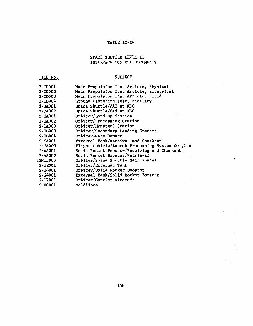
TABLE I X - N
ICD No.
2-CD001 2-CD00 2 2-CD003 2-CD004 2-moo 1 2-OAOO 2 2-u001 2- MOO 2 2- lA00 3 2-1D003 2- 10004 2-2Aoo1 2- 2A003 2-4AOO1 2-4AO0 2 13M15000 2-12001 2- 14001 2- 24001 2- 17001 2-00001
SPACE SHUTTLE LEVEL I1 INTERFACE CONTROL DOCUMENTS
Main Propulsion Test Article, Physical Main Propulsion Test Article, Electrical Main Propulsion Test Article, Fluid Ground Vibration Test, Facility Space ShuttlehAB a t KSC Space Shuttle/Pad at KSC Orbiter /Landing Stat ion Orbiter/Processing Stat ion Orbiter/Hypergol Station Orbiter/Secondary Landing Station Orbiter-Mate-Demate External Tank/Receive and Checkout Flight Vehicle/Launch Processing System Complex Solid Rocket Booster /Receiving and Checkout Solid Rocket Booeter/Retrieval Orbiter/Space Shuttle Main Engine Orbiter /External Tank OrbiterjSolid Rocket Booster External Tank/Solid Rocket Booster Orbiter/Carrier Aircraft Mo Id 1 inee
,
148
SPACE SHUTTLE PROG OFFICE
HDQTRS LEVEL I
SPAC€ SHUTTLE PROGRAM
. LEVEL I I
LEVEL Ill
SHUTTLE
CARRIER
AIRCRAFT
I - LEVEL I V
FIGURE I X - 1

PRCBIGUIBlCCB STRUCTURE
C M S T L I M I T S REVIEW BOARD
, LEVEL I LEVEL I
CLRB PRCB PROGRAM REQUIREMENTS CONTROL BDARD
FIGURE IX-2
........... ...........- ...................... GFE CCB
.
,
SPACE SOLID SHUTTLE ROCK ET ORB1 TER
ENGINE
EXTERNAL
? BOOSTER TANK MA1 N
SHUTTLE K SC C A R R l ER
AIRCRAFT L