task & evaluation outlines
TRANSCRIPT

1-i
Virginia Defense Force
Task & Evaluation Outlines
(T&EO’s)
Change 3
Headquarters Virginia Defense Force
5001 Waller Road Richmond, VA 23230
01 Nov 2017

1-ii
Change 3 Modifications 1. Added: Place PittPak into Service 2. Deleted: Place Vertex Standard VX-410 Radio into Service. This radio has been removed from VDF inventory. 3. Deleted: Place Icom F3/S Radio into Service. This radio has been removed from VDF inventory
1-iii
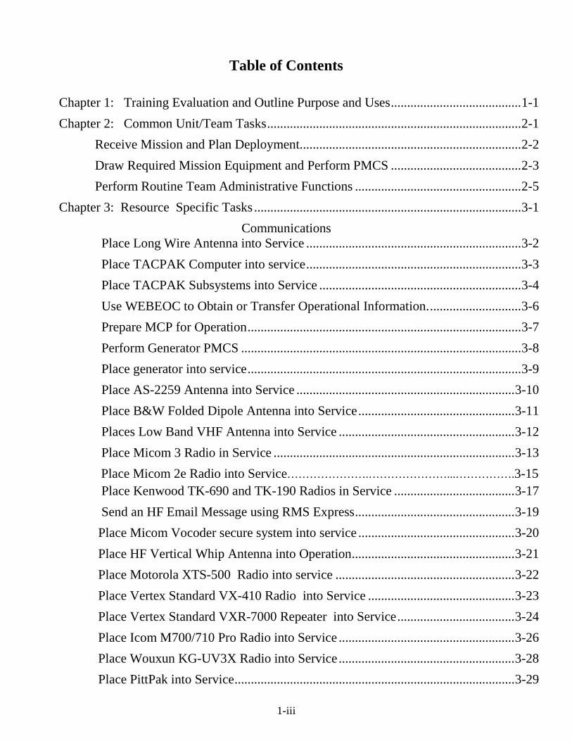
Table of Contents
Chapter 1: Training Evaluation and Outline Purpose and Uses ........................................ 1-1 Chapter 2: Common Unit/Team Tasks .............................................................................. 2-1 Receive Mission and Plan Deployment .................................................................... 2-2 Draw Required Mission Equipment and Perform PMCS ........................................ 2-3 Perform Routine Team Administrative Functions ................................................... 2-5 Chapter 3: Resource Specific Tasks .................................................................................. 3-1
Communications Place Long Wire Antenna into Service .................................................................. 3-2 Place TACPAK Computer into service .................................................................. 3-3 Place TACPAK Subsystems into Service .............................................................. 3-4 Use WEBEOC to Obtain or Transfer Operational Information. ............................ 3-6 Prepare MCP for Operation .................................................................................... 3-7 Perform Generator PMCS ...................................................................................... 3-8 Place generator into service .................................................................................... 3-9 Place AS-2259 Antenna into Service ................................................................... 3-10 Place B&W Folded Dipole Antenna into Service ................................................ 3-11 Places Low Band VHF Antenna into Service ...................................................... 3-12 Place Micom 3 Radio in Service .......................................................................... 3-13 Place Micom 2e Radio into Service………………….…………………...…………….3-15 Place Kenwood TK-690 and TK-190 Radios in Service ..................................... 3-17 Send an HF Email Message using RMS Express ................................................. 3-19 Place Micom Vocoder secure system into service ................................................ 3-20 Place HF Vertical Whip Antenna into Operation .................................................. 3-21 Place Motorola XTS-500 Radio into service ....................................................... 3-22 Place Vertex Standard VX-410 Radio into Service ............................................. 3-23 Place Vertex Standard VXR-7000 Repeater into Service .................................... 3-24 Place Icom M700/710 Pro Radio into Service ...................................................... 3-26 Place Wouxun KG-UV3X Radio into Service ...................................................... 3-28 Place PittPak into Service ...................................................................................... 3-29

1-iv
Place Icom A-110 Radio into Service ................................................................... 3-32 Place Juicebox G2 Power Supply into Service ..................................................... 3-33
Place Verizon MiFi Device into Service ………...……………………….……. 3-35
Driver Training Complete DTC Pre-Training Requirements ............................................................. 3-37 Perform Vehicle Preventative Maintenance Checks and Services (PMCS) ............ 3-38 Perform Vehicle Administrative Functions .............................................................. 3-39 Demonstrate Safe Vehicle Operating Practices........................................................ 3-40
Access Control
Plan and Conduct Access Control Operations ......................................................... 3-41 Plan and Conduct TCP Operations ........................................................................... 3-43
Chapter 4: NGCS Resource Task Situational Training Exercises (STX)
Deploy and Place HFRT into Service .......................................................................... 4-2 Deploy and Place IMAT (TACPAK) Team into Service ............................................ 4-4 Deploy and Place MCP into Service ............................................................................ 4-7 Perform Access Control Duties .................................................................................. 4-10 Deploy and Place STARS Radio Team into Service ................................................. 4-12 Driver Certification.................................................................................................... 4-14 Perform Traffic Control Point Operation ................................................................... 4-17
Appendix A: Forms ........................................................................................................... A-1 Appendix B: Glossary ....................................................................................................... B-1

1-1
Chapter 1
Training Evaluation and Outline Purpose and Uses

1-2
Training and Evaluation Outline Purpose and Uses
1. Purpose: The content of the Training and Evacuation Outline (T&EO) program is intended to provide using personnel with the basic knowledge of their responsibilities while conducting missions in support of the Virginia National Guard. In addition, T&EO’s also provide the VDF leaders and trainers the necessary information required to adequately plan training to support the National Guard Civil Support missions. 2. Scope: The enclosed T&EO’s are applicable for all VDF personnel who are assigned to support Virginia National Guard Civil Support resource teams.
3. Use of T&EO’s: A. Personnel who are responsible for training or deploying VDF resource teams should review the applicable T&EO’s to determine if their teams are properly trained and equipped. Only after a thoughtful and honest evaluation, the leadership can make plans to request the necessary equipment and then schedule the necessary training. This will require cooperation of leaders and NCO’s at all levels of the VDF training system.
B. Chapter 2 contains those T&EO’s which are common to all VDF resource teams. While these are primary “leader” tasks, all team personnel need to be familiar with them and be able to step in and complete these tasks as required. C. Chapter 3, while primarily populated with resource team specific tasks, also contain tasks that are not applicable to any resource teams. These are included because the equipment or task may be useful at a later date.
D. Once the team has been trained, the final Situational Training Exercise (STX) (Chapter 4) will serve as the “beta test” that the team is ready for deployment. If any STX task steps are scored a “No-Go” this serves as a sign that further training is necessary for the team to be ready to be deployed.
1. Suggestions for Corrections: Training programs which are not continuously updated are programs
which will not be meeting the needs of our troops. To this end, suggestions for improvement are encouraged from all users of the VDF T&EO training program. Please send any comments to the ACofS, G3 (ATTN: PME Officer), Waller Depot, 5001 Waller Road, Richmond VA. Suggestions concerning specialized skills can also be sent to the responsible staff section for their review.

2-3
Chapter 2
Common Unit/Team Tasks

2-4
T&EO TASK: Receive Mission and Plan Deployment
ITERATION: 1 2 3 4 5 M (Circle) COMMANDER/LEADER ASSESSMENT: T P U (Circle)
CONDITIONS: The team is conducting support as part of National Guard Civil Support mission and has received an operation order (OPORD) or fragmentary order (FRAGO) in addition to confirmed SAD orders. All necessary personnel and equipment are available. The team has been provided guidance on the required Signal Operating Instructions (SOI) of the supported agency. Strip map and contact information of the supported agency OIC has been provided. Some iterations of this task should be conducted during limited visibility conditions. TASK STANDARDS: The team OIC/NCOIC will, within six (6) hours of receiving mission parameters, reporting locations and reporting contact, contact the team members and prepare deployment plans.
TASK STEPS AND PERFORMANCE MEASURES GO NO-GO This task is a Leader Skill Task to be performed by the team OIC with assistance of the NCOIC. As a
matter of training all subordinate officers and NCO's should be cross trained on these task steps. 1. Activates the team phone tree and gives activation FRAGO. Specify: a. Assembly Point (AP) b. Time of assembly. c. Anticipated mission length d. Other pertinent mission details required
2. Review Operation Order (OPORD) received. (Note that it is rare that a full written OPORD will be received. Usually a verbal WARNO followed by a FRAGO will be received. The OIC must request additional instructions if the required information are not supplied. At a minimum he must receive:
a. Date/Time/Group (DTG) that activation orders are effective. b. Exact location to report to. c. Person to report to. d. Contact information of the person reporting to. e. Reporting DTG f. Changes/additions to published Signal Operating Instructions (SOI)
3. Perform map recon of the route march. Prepare strip maps to be given to all vehicles in the movement
serial.
4. Review Risk Assessment Worksheets. Have any conditions/events altered the prepared risk assessment? If so, revise the Risk Assessment Worksheet. Have unit commander approve if the residual risk is upgraded.
5. Develops and gives safety briefing to team members before leaving home station. 6. 72 Hour Basic Load is checked. Shortages are remedied.
TASK PERFORMANCE / EVALUATION SUMMARY BLOCK
ITERATION 1 2 3 4 5 M TOTAL TOTAL TASK STEPS EVALUATED TOTAL TASK STEPS “GO” TRAINING STATUS “GO”/“NO-GO” “*” indicates a leader task step.
2-5
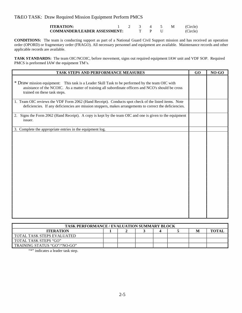
T&EO TASK: Draw Required Mission Equipment Perform PMCS
ITERATION: 1 2 3 4 5 M (Circle) COMMANDER/LEADER ASSESSMENT: T P U (Circle)
CONDITIONS: The team is conducting support as part of a National Guard Civil Support mission and has received an operation order (OPORD) or fragmentary order (FRAGO). All necessary personnel and equipment are available. Maintenance records and other applicable records are available. TASK STANDARDS: The team OIC/NCOIC, before movement, signs out required equipment IAW unit and VDF SOP. Required PMCS is preformed IAW the equipment TM’s.
TASK STEPS AND PERFORMANCE MEASURES GO NO-GO * Draw mission equipment: This task is a Leader Skill Task to be performed by the team OIC with
assistance of the NCOIC. As a matter of training all subordinate officers and NCO's should be cross trained on these task steps.
1. Team OIC reviews the VDF Form 2062 (Hand Receipt). Conducts spot check of the listed items. Note deficiencies. If any deficiencies are mission stoppers, makes arrangements to correct the deficiencies.
2. Signs the Form 2062 (Hand Receipt). A copy is kept by the team OIC and one is given to the equipment issuer.
3. Complete the appropriate entries in the equipment log.
TASK PERFORMANCE / EVALUATION SUMMARY BLOCK
ITERATION 1 2 3 4 5 M TOTAL TOTAL TASK STEPS EVALUATED TOTAL TASK STEPS “GO” TRAINING STATUS “GO”/“NO-GO” “*” indicates a leader task step.
2-6
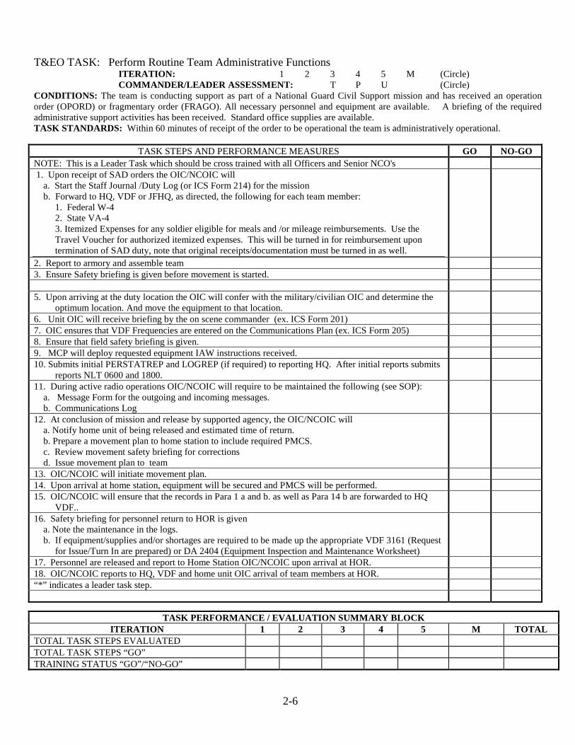
T&EO TASK: Perform Routine Team Administrative Functions
ITERATION: 1 2 3 4 5 M (Circle) COMMANDER/LEADER ASSESSMENT: T P U (Circle)
CONDITIONS: The team is conducting support as part of a National Guard Civil Support mission and has received an operation order (OPORD) or fragmentary order (FRAGO). All necessary personnel and equipment are available. A briefing of the required administrative support activities has been received. Standard office supplies are available. TASK STANDARDS: Within 60 minutes of receipt of the order to be operational the team is administratively operational.
TASK STEPS AND PERFORMANCE MEASURES GO NO-GO NOTE: This is a Leader Task which should be cross trained with all Officers and Senior NCO's 1. Upon receipt of SAD orders the OIC/NCOIC will a. Start the Staff Journal /Duty Log (or ICS Form 214) for the mission b. Forward to HQ, VDF or JFHQ, as directed, the following for each team member: 1. Federal W-4 2. State VA-4 3. Itemized Expenses for any soldier eligible for meals and /or mileage reimbursements. Use the
Travel Voucher for authorized itemized expenses. This will be turned in for reimbursement upon termination of SAD duty, note that original receipts/documentation must be turned in as well.
2. Report to armory and assemble team 3. Ensure Safety briefing is given before movement is started. 5. Upon arriving at the duty location the OIC will confer with the military/civilian OIC and determine the
optimum location. And move the equipment to that location.
6. Unit OIC will receive briefing by the on scene commander (ex. ICS Form 201) 7. OIC ensures that VDF Frequencies are entered on the Communications Plan (ex. ICS Form 205) 8. Ensure that field safety briefing is given. 9. MCP will deploy requested equipment IAW instructions received. 10. Submits initial PERSTATREP and LOGREP (if required) to reporting HQ. After initial reports submits
reports NLT 0600 and 1800.
11. During active radio operations OIC/NCOIC will require to be maintained the following (see SOP): a. Message Form for the outgoing and incoming messages. b. Communications Log
12. At conclusion of mission and release by supported agency, the OIC/NCOIC will a. Notify home unit of being released and estimated time of return. b. Prepare a movement plan to home station to include required PMCS. c. Review movement safety briefing for corrections d. Issue movement plan to team
13. OIC/NCOIC will initiate movement plan. 14. Upon arrival at home station, equipment will be secured and PMCS will be performed. 15. OIC/NCOIC will ensure that the records in Para 1 a and b. as well as Para 14 b are forwarded to HQ
VDF..
16. Safety briefing for personnel return to HOR is given a. Note the maintenance in the logs. b. If equipment/supplies and/or shortages are required to be made up the appropriate VDF 3161 (Request
for Issue/Turn In are prepared) or DA 2404 (Equipment Inspection and Maintenance Worksheet)
17. Personnel are released and report to Home Station OIC/NCOIC upon arrival at HOR. 18. OIC/NCOIC reports to HQ, VDF and home unit OIC arrival of team members at HOR. “*” indicates a leader task step.
TASK PERFORMANCE / EVALUATION SUMMARY BLOCK ITERATION 1 2 3 4 5 M TOTAL
TOTAL TASK STEPS EVALUATED TOTAL TASK STEPS “GO” TRAINING STATUS “GO”/“NO-GO”
3-1
Chapter 3
Skill Specific Tasks

3-2
T&EO TASK: Place Long Wire Antenna into Service.
ITERATION: 1 2 3 4 5 M (Circle) COMMANDER/LEADER ASSESSMENT: T P U (Circle)
CONDITIONS: The team is conducting communications support as part of a National Guard Civil Support mission and has received an operation order (OPORD) or fragmentary order (FRAGO). All necessary personnel and equipment are available. The team has been moved to the desired location and orders to deploy a long wire antenna have been issued by the team OIC/NCOIC. TASK STANDARDS: The team will, within 30 minutes, safely deploy the long wire antenna and connect the operational antenna to the HF radio tuner.
TASK STEPS AND PERFORMANCE MEASURES GO NO-GO Safety: Antennas must be separated from power lines by a distance equal to twice the height of the antenna.
Antenna contact with power lines may cause serious injury or even death to the operator. Be sure transmitter power is off. Contacting the antenna when the transmitter is keyed will cause electrical burns
NOTE: There are many different ways to erect this type of antenna. The evaluator should be familiar with the technique in order to be able to render an objective evaluation of the teams’ antenna. The following directions are for an “L” configuration. This type of antenna does not have to be high off the ground; a couple of feet will do.
1. Locate the long wire antenna, grounding stakes, hammer, and paracord. 2. Determine the location of the tuner. Drive a grounding stake into the ground. 3. Unroll the long wire antenna, advoiding kinks. Connect one end of the antenna paracord to the
grounding stake. Note: Attach the paracord, not the spade terminal to the grounding stake.
4. Using the plastic insulator and para cord, attach the insulator to a support (tree, mast, or other support) at the middle of the antenna.
5. Stretch out the antenna 90 degrees to initial run of the antenna. 6. Secure the 90 degree run to the antenna to a support (tree, mast, or any other available support). 7. Connect the spade terminal to the tuner high tension lead. (the other end spade terminal is not
connected to anything, but make sure it is not grounded)
8. Flag guy ropes or barricade to prevent tripping hazard. Use chem lights, if available, during night operations.
9. To secure antenna, reverse the above steps.
TASK PERFORMANCE / EVALUATION SUMMARY BLOCK
ITERATION 1 2 3 4 5 M TOTAL TOTAL TASK STEPS EVALUATED TOTAL TASK STEPS “GO” TRAINING STATUS “GO”/“NO-GO” “*” indicates a leader task step.
3-3
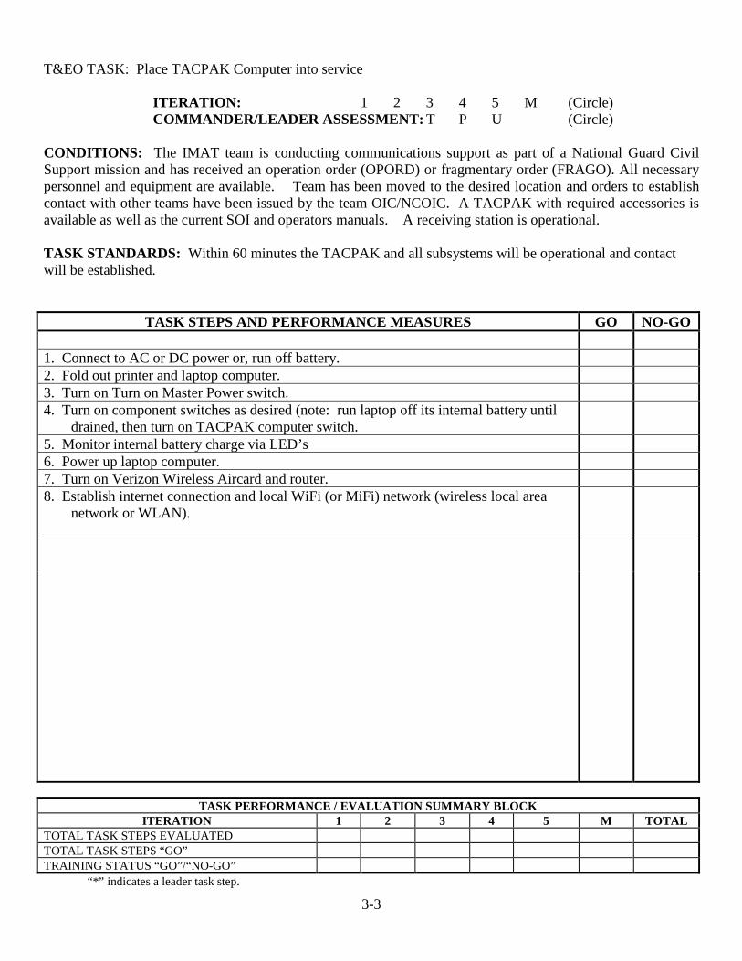
T&EO TASK: Place TACPAK Computer into service
ITERATION: 1 2 3 4 5 M (Circle) COMMANDER/LEADER ASSESSMENT: T P U (Circle)
CONDITIONS: The IMAT team is conducting communications support as part of a National Guard Civil Support mission and has received an operation order (OPORD) or fragmentary order (FRAGO). All necessary personnel and equipment are available. Team has been moved to the desired location and orders to establish contact with other teams have been issued by the team OIC/NCOIC. A TACPAK with required accessories is available as well as the current SOI and operators manuals. A receiving station is operational. TASK STANDARDS: Within 60 minutes the TACPAK and all subsystems will be operational and contact will be established.
TASK STEPS AND PERFORMANCE MEASURES GO NO-GO 1. Connect to AC or DC power or, run off battery. 2. Fold out printer and laptop computer. 3. Turn on Turn on Master Power switch. 4. Turn on component switches as desired (note: run laptop off its internal battery until
drained, then turn on TACPAK computer switch.
5. Monitor internal battery charge via LED’s 6. Power up laptop computer. 7. Turn on Verizon Wireless Aircard and router. 8. Establish internet connection and local WiFi (or MiFi) network (wireless local area
network or WLAN).
TASK PERFORMANCE / EVALUATION SUMMARY BLOCK
ITERATION 1 2 3 4 5 M TOTAL TOTAL TASK STEPS EVALUATED TOTAL TASK STEPS “GO” TRAINING STATUS “GO”/“NO-GO” “*” indicates a leader task step.

3-4
T&EO TASK: Place TACPAK Subsystems into Service
ITERATION: 1 2 3 4 5 M (Circle) COMMANDER/LEADER ASSESSMENT: T P U (Circle)
CONDITIONS: The team is conducting communications support as part of a National Guard Civil Support mission and has received an operation order (OPORD) or fragmentary order (FRAGO). All necessary personnel and equipment are available. The team has been moved to the desired location and orders to deploy the TACPAK have been issued by the team OIC/NCOIC. TASK STANDARDS: Within 60 minutes the TACPAK and all subsystems will be operational and contact will be established.
TASK STEPS AND PERFORMANCE MEASURES GO NO-GO Note: This may be considered a sub task of “Placing TACPAK into Use”. It has been
separated for ease of training/evaluation.
Place Scanner into Operation 1. Insert scanner USB cable into laptop port. 2.Wait for scanner to be recognized by computer 3.Insert page face down into scanner. Page will be automatically pulled through
scanner and image displayed on laptop. 4.If scanned document is poor quality, recalibrate scanner by selecting Start/Devices
and Printers on laptop. Right click on XP100 and select ”Calibrate”.
Copier 1. Scan the document and print multiple copies. (note: this is not intended for large
numbers of copies)
GPS/Mapping Operation 1. Mount Garmin AERO GPS (or comparable) unit, with sky view, to TACPAK case or
use vehicle mount. 2. Turn on and select ground/air mode from screen by touching the associated airplane or
car icon at top of the screen. 3. Create routes using screen icons. 4. Charge GPS by removing battery cover and inserting 12v USB cable into USB port, or
use DC cigarette socket charger which connects to the side of the ball mount. Note: USB port visible on back of GPS is for an external antenna connection and will
NOT charge the battery.
Sony Video Camera Operation 1. Charge video camera battery by plugging AC charger between TACPAK and video
camera obtaining separate (optional) AC battery charging cradle. 2. Insert SD card. 3. Create and review video. 4. Video transfer to TACPAK by removing SD card from camera and inserting into
laptop SD card reader slot.
Page 1 of 2
3-5
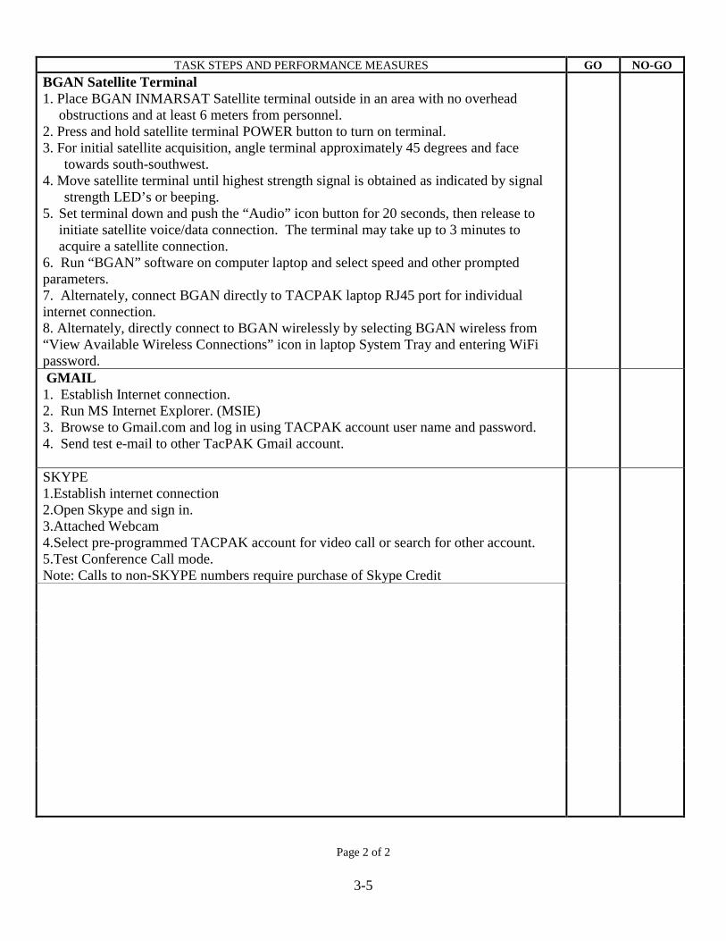
TASK STEPS AND PERFORMANCE MEASURES GO NO-GO
BGAN Satellite Terminal 1. Place BGAN INMARSAT Satellite terminal outside in an area with no overhead
obstructions and at least 6 meters from personnel. 2. Press and hold satellite terminal POWER button to turn on terminal. 3. For initial satellite acquisition, angle terminal approximately 45 degrees and face
towards south-southwest. 4. Move satellite terminal until highest strength signal is obtained as indicated by signal
strength LED’s or beeping. 5. Set terminal down and push the “Audio” icon button for 20 seconds, then release to
initiate satellite voice/data connection. The terminal may take up to 3 minutes to acquire a satellite connection.
6. Run “BGAN” software on computer laptop and select speed and other prompted parameters. 7. Alternately, connect BGAN directly to TACPAK laptop RJ45 port for individual internet connection. 8. Alternately, directly connect to BGAN wirelessly by selecting BGAN wireless from “View Available Wireless Connections” icon in laptop System Tray and entering WiFi password.
GMAIL 1. Establish Internet connection. 2. Run MS Internet Explorer. (MSIE) 3. Browse to Gmail.com and log in using TACPAK account user name and password. 4. Send test e-mail to other TacPAK Gmail account.
SKYPE 1.Establish internet connection 2.Open Skype and sign in. 3.Attached Webcam 4.Select pre-programmed TACPAK account for video call or search for other account. 5.Test Conference Call mode. Note: Calls to non-SKYPE numbers require purchase of Skype Credit
Page 2 of 2
3-6
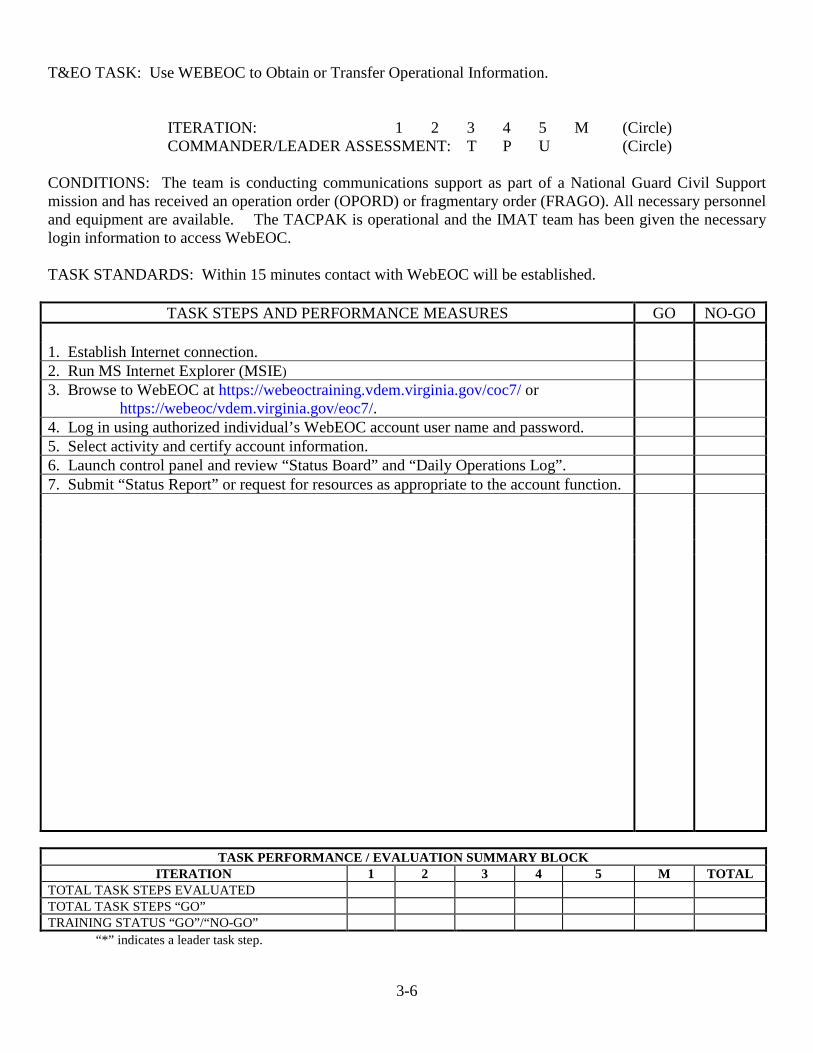
T&EO TASK: Use WEBEOC to Obtain or Transfer Operational Information.
ITERATION: 1 2 3 4 5 M (Circle) COMMANDER/LEADER ASSESSMENT: T P U (Circle)
CONDITIONS: The team is conducting communications support as part of a National Guard Civil Support mission and has received an operation order (OPORD) or fragmentary order (FRAGO). All necessary personnel and equipment are available. The TACPAK is operational and the IMAT team has been given the necessary login information to access WebEOC. TASK STANDARDS: Within 15 minutes contact with WebEOC will be established.
TASK STEPS AND PERFORMANCE MEASURES GO NO-GO 1. Establish Internet connection. 2. Run MS Internet Explorer (MSIE) 3. Browse to WebEOC at https://webeoctraining.vdem.virginia.gov/coc7/ or
https://webeoc/vdem.virginia.gov/eoc7/.
4. Log in using authorized individual’s WebEOC account user name and password. 5. Select activity and certify account information. 6. Launch control panel and review “Status Board” and “Daily Operations Log”. 7. Submit “Status Report” or request for resources as appropriate to the account function.
TASK PERFORMANCE / EVALUATION SUMMARY BLOCK
ITERATION 1 2 3 4 5 M TOTAL TOTAL TASK STEPS EVALUATED TOTAL TASK STEPS “GO” TRAINING STATUS “GO”/“NO-GO” “*” indicates a leader task step.

3-7
T&EO TASK: Prepare MCP for Operation
ITERATION: 1 2 3 4 5 M (Circle) COMMANDER/LEADER ASSESSMENT: T P U (Circle)
CONDITIONS: The MCP is conducting communications support as part of a National Guard Civil Support mission and has received an operation order (OPORD) or fragmentary order (FRAGO). All necessary personnel and equipment are available. The MCP has been provided guidance on Signal Operating Instructions (SOI) of the supported agency. Strip map and contact information of the supported agency OIC has been provided. MCP has been moved to the desired location. TASK STANDARDS: MCP team will within 60 minutes of reaching the desired duty site complete the required measures to place the MCP into operation.
TASK STEPS AND PERFORMANCE MEASURES GO NO-GO 1. Conduct safety brief 2. Remove MCP from truck by lowering tongue leg. Use a wooden block to support
tongue weight. Disconnect trailer from truck.
3. Lower front and rear leveling legs. Use wooden block under leveling leg. 4. Prepare genset. Follow safety procedures for genset PCMS. Refuel a cool genset only. 5. Ground MCP from the frame to an earth ground rod. Run the panel ground to the earth
ground rod.
6. Start genset. Follow genset procedures. 7. To power trailer, turn on each main, then each branch breaker. To power down, turn
off branches first then main.
7. Lower tailgate if desired. Place warning ribbons on the tailgate cables. 8. Erect/Install antennas as required by the mission. 9. Erect tarps as required to keep MCP comfortable 10. To secure from mission, follow steps 2 thru 9 in reverse order.
TASK PERFORMANCE / EVALUATION SUMMARY BLOCK
ITERATION 1 2 3 4 5 M TOTAL TOTAL TASK STEPS EVALUATED TOTAL TASK STEPS “GO” TRAINING STATUS “GO”/“NO-GO” “*” indicates a leader task step.
3-8
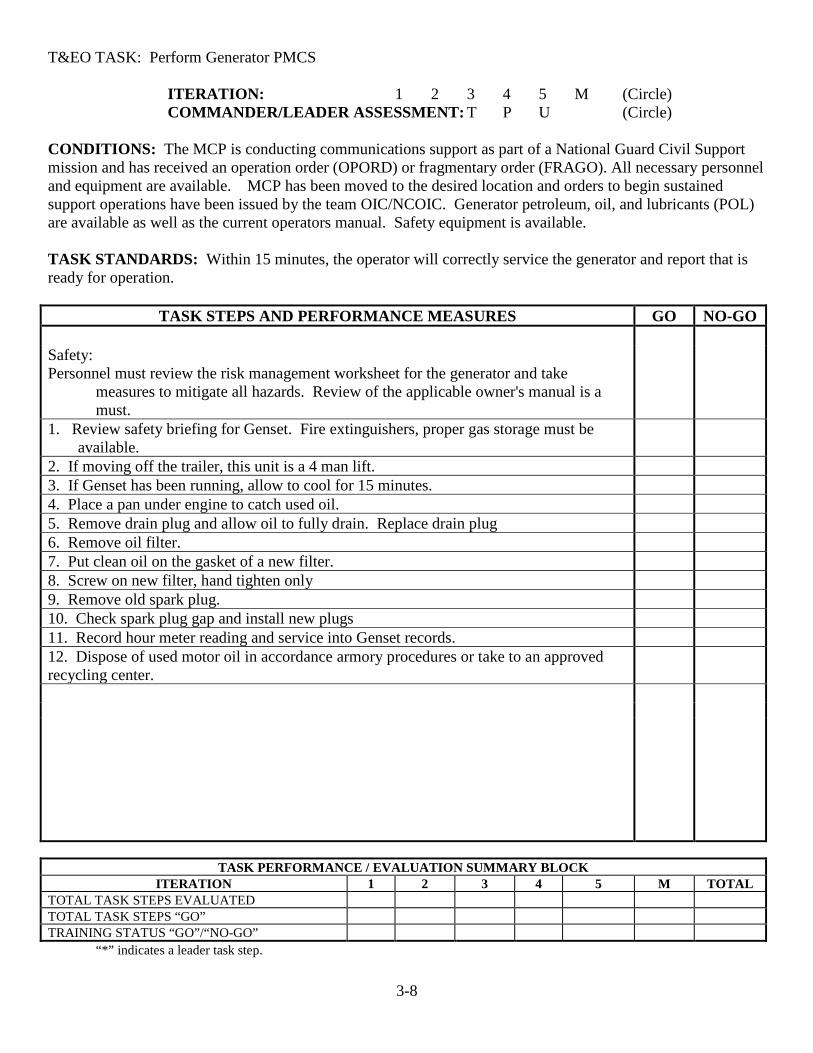
T&EO TASK: Perform Generator PMCS
ITERATION: 1 2 3 4 5 M (Circle) COMMANDER/LEADER ASSESSMENT: T P U (Circle)
CONDITIONS: The MCP is conducting communications support as part of a National Guard Civil Support mission and has received an operation order (OPORD) or fragmentary order (FRAGO). All necessary personnel and equipment are available. MCP has been moved to the desired location and orders to begin sustained support operations have been issued by the team OIC/NCOIC. Generator petroleum, oil, and lubricants (POL) are available as well as the current operators manual. Safety equipment is available. TASK STANDARDS: Within 15 minutes, the operator will correctly service the generator and report that is ready for operation.
TASK STEPS AND PERFORMANCE MEASURES GO NO-GO Safety: Personnel must review the risk management worksheet for the generator and take
measures to mitigate all hazards. Review of the applicable owner's manual is a must.
1. Review safety briefing for Genset. Fire extinguishers, proper gas storage must be available.
2. If moving off the trailer, this unit is a 4 man lift. 3. If Genset has been running, allow to cool for 15 minutes. 4. Place a pan under engine to catch used oil. 5. Remove drain plug and allow oil to fully drain. Replace drain plug 6. Remove oil filter. 7. Put clean oil on the gasket of a new filter. 8. Screw on new filter, hand tighten only 9. Remove old spark plug. 10. Check spark plug gap and install new plugs 11. Record hour meter reading and service into Genset records. 12. Dispose of used motor oil in accordance armory procedures or take to an approved recycling center.
TASK PERFORMANCE / EVALUATION SUMMARY BLOCK
ITERATION 1 2 3 4 5 M TOTAL TOTAL TASK STEPS EVALUATED TOTAL TASK STEPS “GO” TRAINING STATUS “GO”/“NO-GO” “*” indicates a leader task step.
3-9
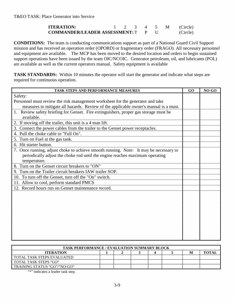
T&EO TASK: Place Generator into Service
ITERATION: 1 2 3 4 5 M (Circle) COMMANDER/LEADER ASSESSMENT: T P U (Circle)
CONDITIONS: The team is conducting communications support as part of a National Guard Civil Support mission and has received an operation order (OPORD) or fragmentary order (FRAGO). All necessary personnel and equipment are available. The MCP has been moved to the desired location and orders to begin sustained support operations have been issued by the team OIC/NCOIC. Generator petroleum, oil, and lubricants (POL) are available as well as the current operators manual. Safety equipment is available TASK STANDARDS: Within 10 minutes the operator will start the generator and indicate what steps are required for continuous operation.
TASK STEPS AND PERFORMANCE MEASURES GO NO-GO Safety: Personnel must review the risk management worksheet for the generator and take
measures to mitigate all hazards. Review of the applicable owner's manual is a must.
1. Review safety briefing for Genset. Fire extinguishers, proper gas storage must be available.
2. If moving off the trailer, this unit is a 4 man lift. 3. Connect the power cables from the trailer to the Genset power receptacles. 4. Pull the choke cable to "Full On". 5. Turn on Fuel at the gas tank. 6. Hit starter button. 7. Once running, adjust choke to achieve smooth running. Note: It may be necessary to
periodically adjust the choke rod until the engine reaches maximum operating temperature.
8. Turn on the Genset circuit breakers to "ON" 9. Turn on the Trailer circuit breakers IAW trailer SOP. 10. To turn off the Genset, turn off the "On" switch. 11. Allow to cool, perform standard PMCS 12. Record hours run on Genset maintenance record.
TASK PERFORMANCE / EVALUATION SUMMARY BLOCK
ITERATION 1 2 3 4 5 M TOTAL TOTAL TASK STEPS EVALUATED TOTAL TASK STEPS “GO” TRAINING STATUS “GO”/“NO-GO” “*” indicates a leader task step.
3-10
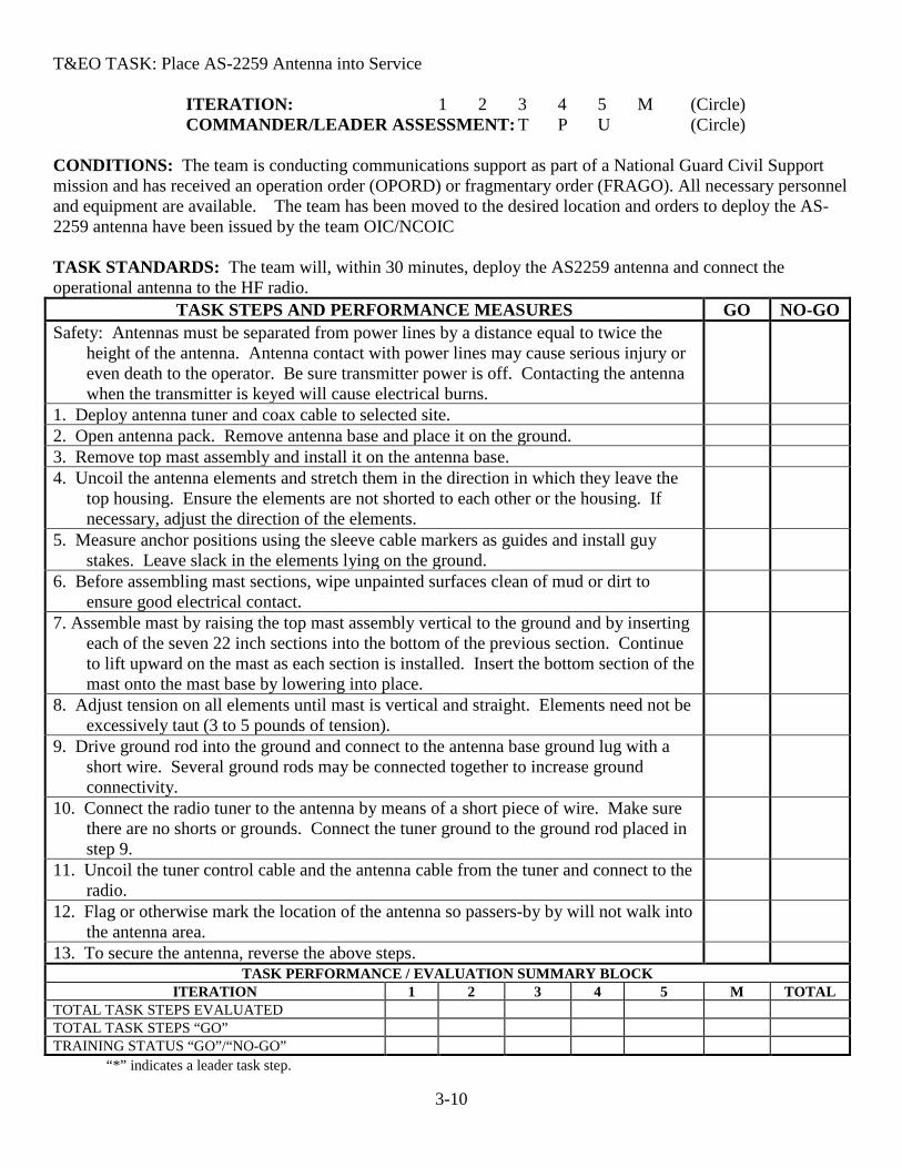
T&EO TASK: Place AS-2259 Antenna into Service
ITERATION: 1 2 3 4 5 M (Circle) COMMANDER/LEADER ASSESSMENT: T P U (Circle)
CONDITIONS: The team is conducting communications support as part of a National Guard Civil Support mission and has received an operation order (OPORD) or fragmentary order (FRAGO). All necessary personnel and equipment are available. The team has been moved to the desired location and orders to deploy the AS-2259 antenna have been issued by the team OIC/NCOIC TASK STANDARDS: The team will, within 30 minutes, deploy the AS2259 antenna and connect the operational antenna to the HF radio.
TASK STEPS AND PERFORMANCE MEASURES GO NO-GO Safety: Antennas must be separated from power lines by a distance equal to twice the
height of the antenna. Antenna contact with power lines may cause serious injury or even death to the operator. Be sure transmitter power is off. Contacting the antenna when the transmitter is keyed will cause electrical burns.
1. Deploy antenna tuner and coax cable to selected site. 2. Open antenna pack. Remove antenna base and place it on the ground. 3. Remove top mast assembly and install it on the antenna base. 4. Uncoil the antenna elements and stretch them in the direction in which they leave the
top housing. Ensure the elements are not shorted to each other or the housing. If necessary, adjust the direction of the elements.
5. Measure anchor positions using the sleeve cable markers as guides and install guy stakes. Leave slack in the elements lying on the ground.
6. Before assembling mast sections, wipe unpainted surfaces clean of mud or dirt to ensure good electrical contact.
7. Assemble mast by raising the top mast assembly vertical to the ground and by inserting each of the seven 22 inch sections into the bottom of the previous section. Continue to lift upward on the mast as each section is installed. Insert the bottom section of the mast onto the mast base by lowering into place.
8. Adjust tension on all elements until mast is vertical and straight. Elements need not be excessively taut (3 to 5 pounds of tension).
9. Drive ground rod into the ground and connect to the antenna base ground lug with a short wire. Several ground rods may be connected together to increase ground connectivity.
10. Connect the radio tuner to the antenna by means of a short piece of wire. Make sure there are no shorts or grounds. Connect the tuner ground to the ground rod placed in step 9.
11. Uncoil the tuner control cable and the antenna cable from the tuner and connect to the radio.
12. Flag or otherwise mark the location of the antenna so passers-by by will not walk into the antenna area.
13. To secure the antenna, reverse the above steps. TASK PERFORMANCE / EVALUATION SUMMARY BLOCK
ITERATION 1 2 3 4 5 M TOTAL TOTAL TASK STEPS EVALUATED TOTAL TASK STEPS “GO” TRAINING STATUS “GO”/“NO-GO” “*” indicates a leader task step.

3-11
T&EO TASK: Place B&W Folded Dipole Antenna into Service.
ITERATION: 1 2 3 4 5 M (Circle) COMMANDER/LEADER ASSESSMENT: T P U (Circle)
CONDITIONS: The team is conducting communications support as part of a National Guard Civil Support mission and has received an operation order (OPORD) or fragmentary order (FRAGO). All necessary personnel and equipment are available. The team has been moved to the desired location and orders to deploy the B&W Long wire antenna have been issued by the team OIC/NCOIC. TASK STANDARDS: The team will, within 30 minutes, erect the B&W folded dipole antenna and connect the operational antenna to the MCP HF radio.
TASK STEPS AND PERFORMANCE MEASURES GO NO-GO
1. Locate the B&W antenna. 2. Locate two (2) mast assemblies, stakes, and guy ropes. 3. Erect mast and attach insulator to mast eyelet with short rope. Secure the mast
with appropriate guy wire/ropes.
4. Connect end of antenna coax cable to the coax terminal at the mid point of the antenna.
5. Erect mast at the distal end of the antenna and use guy wire/ropes to secure it plumb
6. Pull attachment rope down through eyelet and secure on clevis on mast. (not all masts have this feature)
NOTE: Antenna insulator should be several feet away from mast when installed. 7. Attach antenna coax to the radio antenna connection. 8. Flag all guy ropes or barricade to prevent tripping hazard. 9. To secure antenna, reverse the above steps.
TASK PERFORMANCE / EVALUATION SUMMARY BLOCK
ITERATION 1 2 3 4 5 M TOTAL TOTAL TASK STEPS EVALUATED TOTAL TASK STEPS “GO” TRAINING STATUS “GO”/“NO-GO” “*” indicates a leader task step.
3-12
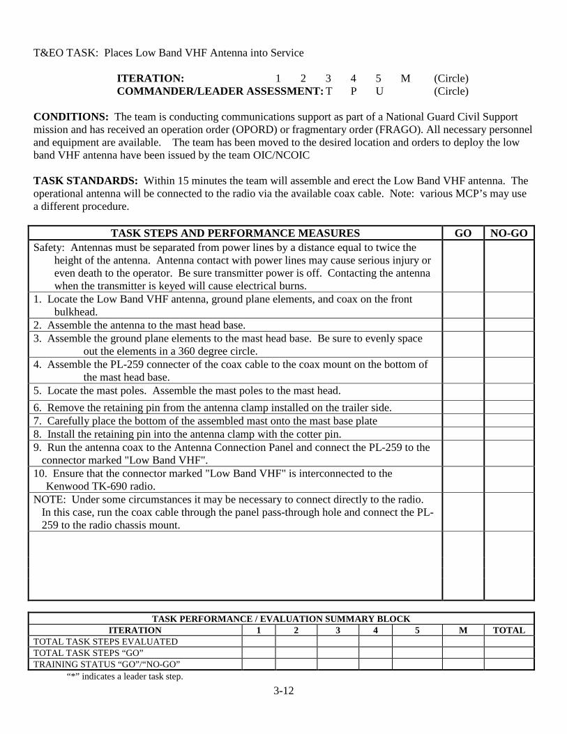
T&EO TASK: Places Low Band VHF Antenna into Service
ITERATION: 1 2 3 4 5 M (Circle) COMMANDER/LEADER ASSESSMENT: T P U (Circle)
CONDITIONS: The team is conducting communications support as part of a National Guard Civil Support mission and has received an operation order (OPORD) or fragmentary order (FRAGO). All necessary personnel and equipment are available. The team has been moved to the desired location and orders to deploy the low band VHF antenna have been issued by the team OIC/NCOIC TASK STANDARDS: Within 15 minutes the team will assemble and erect the Low Band VHF antenna. The operational antenna will be connected to the radio via the available coax cable. Note: various MCP’s may use a different procedure.
TASK STEPS AND PERFORMANCE MEASURES GO NO-GO Safety: Antennas must be separated from power lines by a distance equal to twice the
height of the antenna. Antenna contact with power lines may cause serious injury or even death to the operator. Be sure transmitter power is off. Contacting the antenna when the transmitter is keyed will cause electrical burns.
1. Locate the Low Band VHF antenna, ground plane elements, and coax on the front bulkhead.
2. Assemble the antenna to the mast head base. 3. Assemble the ground plane elements to the mast head base. Be sure to evenly space
out the elements in a 360 degree circle.
4. Assemble the PL-259 connecter of the coax cable to the coax mount on the bottom of the mast head base.
5. Locate the mast poles. Assemble the mast poles to the mast head. 6. Remove the retaining pin from the antenna clamp installed on the trailer side. 7. Carefully place the bottom of the assembled mast onto the mast base plate 8. Install the retaining pin into the antenna clamp with the cotter pin. 9. Run the antenna coax to the Antenna Connection Panel and connect the PL-259 to the
connector marked "Low Band VHF".
10. Ensure that the connector marked "Low Band VHF" is interconnected to the Kenwood TK-690 radio.
NOTE: Under some circumstances it may be necessary to connect directly to the radio. In this case, run the coax cable through the panel pass-through hole and connect the PL-259 to the radio chassis mount.
TASK PERFORMANCE / EVALUATION SUMMARY BLOCK
ITERATION 1 2 3 4 5 M TOTAL TOTAL TASK STEPS EVALUATED TOTAL TASK STEPS “GO” TRAINING STATUS “GO”/“NO-GO” “*” indicates a leader task step.
3-13
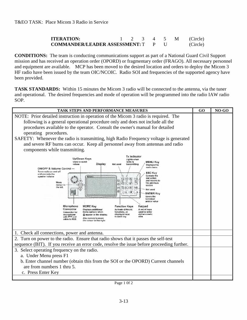
T&EO TASK: Place Micom 3 Radio in Service
ITERATION: 1 2 3 4 5 M (Circle) COMMANDER/LEADER ASSESSMENT: T P U (Circle)
CONDITIONS: The team is conducting communications support as part of a National Guard Civil Support mission and has received an operation order (OPORD) or fragmentary order (FRAGO). All necessary personnel and equipment are available. MCP has been moved to the desired location and orders to deploy the Micom 3 HF radio have been issued by the team OIC/NCOIC. Radio SOI and frequencies of the supported agency have been provided. TASK STANDARDS: Within 15 minutes the Micom 3 radio will be connected to the antenna, via the tuner and operational. The desired frequencies and mode of operation will be programmed into the radio IAW radio SOP.
TASK STEPS AND PERFORMANCE MEASURES GO NO-GO NOTE: Prior detailed instruction in operation of the Micom 3 radio is required. The
following is a general operational procedure only and does not include all the procedures available to the operator. Consult the owner's manual for detailed operating procedures.
SAFETY: Whenever the radio is transmitting, high Radio Frequency voltage is generated and severe RF burns can occur. Keep all personnel away from antennas and radio components while transmitting.
1. Check all connections, power and antenna. 2. Turn on power to the radio. Ensure that radio shows that it passes the self-test sequence (BIT). If you receive an error code, resolve the issue before proceeding further.
3. Select operating frequency on the radio. a. Under Menu press F1 b. Enter channel number (obtain this from the SOI or the OPORD) Current channels
are from numbers 1 thru 5. c. Press Enter Key
Page 1 0f 2

3-14
TASK STEPS AND PERFORMANCE MEASURES GO NO-GO
4. Use microphone to conduct voice communications. When using secure communications, you must use the microphone attached to the vocoder unit. (Military classified traffic cannot be transmitted over this secure system). You can transfer the radio microphone to the Vocoder if necessary.
5. To access HF email: A computer must be connected to the radio and loaded with the appropriate software. See the unit S6 if this has not been done.
a. Turn on Power strip to apply power to modem, vocoder, fax modem, and Motorola data modem.
b. .Open RMS Express on computer- allow to initialize c. Select MARS station with a 600 mile or less distance when using the AS-2259 or
similar NVIS antenna d. Select center frequency with (13) next to the frequency. e. Dial in the USB frequency. f. Connect to send and receive traffic.
6. To remove from service, turn off power. NOTE: The Micom 3t radio is a software defined radio. This means that you must enter commands via the front panel keys. The following are some of the most common used key commands. The radio manual lists all the options available.
Select Channel Mode Menu.>CHAN(F1)>Select Channel>ENTER
To Change Current Frequency MENU>FREQ(F2)>MORE>T/R(F1)>Type the frequency you desire>ENTER
Use BIT Mode (checks for malfunctions) MENU>BITE>FULL(F1)
Select Transmitting Power MENU>CHAN(F1)>MORE>F1>Select power range>ENTER
Enter ALE Mode MENU>ALE(F3)>Select desired net>ENTER
Turn Tuner Control Off/On. NOTE: When using the AS-2259 or long wire antenna with the external tuner, the tuner option MUST be turned ON. This sets the radio to pass power and control data to the tuner via the coaxial cable. When using the B&W antenna the internal option must be OFF.
MENU>MORE>PROG(F2)>RAD(F1)> OPTS(F3)>TUNE >Toggle to the desired condition>ENTER
TASK PERFORMANCE / EVALUATION SUMMARY BLOCK ITERATION 1 2 3 4 5 M TOTAL
TOTAL TASK STEPS EVALUATED TOTAL TASK STEPS “GO” TRAINING STATUS “GO”/“NO-GO” “*” indicates a leader task step.
Page 2 of 2
3-15
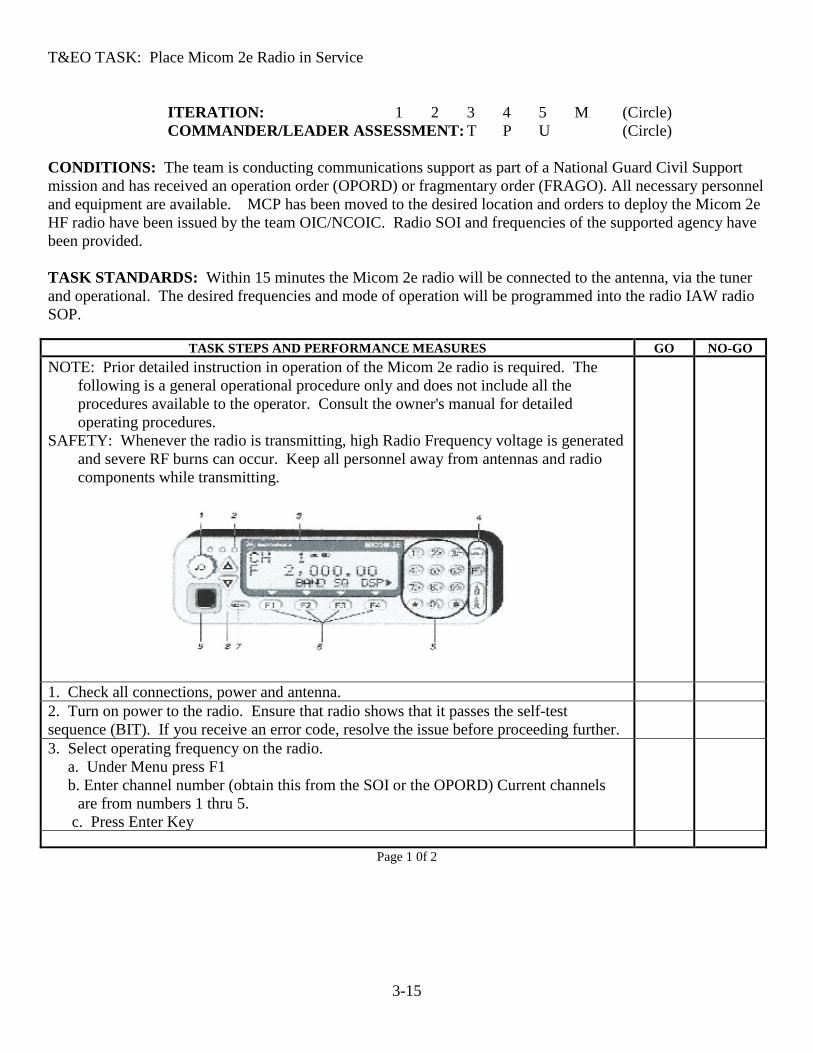
T&EO TASK: Place Micom 2e Radio in Service
ITERATION: 1 2 3 4 5 M (Circle) COMMANDER/LEADER ASSESSMENT: T P U (Circle)
CONDITIONS: The team is conducting communications support as part of a National Guard Civil Support mission and has received an operation order (OPORD) or fragmentary order (FRAGO). All necessary personnel and equipment are available. MCP has been moved to the desired location and orders to deploy the Micom 2e HF radio have been issued by the team OIC/NCOIC. Radio SOI and frequencies of the supported agency have been provided. TASK STANDARDS: Within 15 minutes the Micom 2e radio will be connected to the antenna, via the tuner and operational. The desired frequencies and mode of operation will be programmed into the radio IAW radio SOP.
TASK STEPS AND PERFORMANCE MEASURES GO NO-GO NOTE: Prior detailed instruction in operation of the Micom 2e radio is required. The
following is a general operational procedure only and does not include all the procedures available to the operator. Consult the owner's manual for detailed operating procedures.
SAFETY: Whenever the radio is transmitting, high Radio Frequency voltage is generated and severe RF burns can occur. Keep all personnel away from antennas and radio components while transmitting.
1. Check all connections, power and antenna. 2. Turn on power to the radio. Ensure that radio shows that it passes the self-test sequence (BIT). If you receive an error code, resolve the issue before proceeding further.
3. Select operating frequency on the radio. a. Under Menu press F1 b. Enter channel number (obtain this from the SOI or the OPORD) Current channels
are from numbers 1 thru 5. c. Press Enter Key
Page 1 0f 2

3-16
TASK STEPS AND PERFORMANCE MEASURES GO NO-GO
4. Use microphone to conduct voice communications. When using secure communications, you must use the microphone attached to the vocoder unit. (Military classified traffic cannot be transmitted over this secure system). You can transfer the radio microphone to the Vocoder if necessary.
5. To access HF email: A computer must be connected to the radio and loaded with the appropriate software. See the unit S6 if this has not been done.
a. Turn on Power strip to apply power to modem, vocoder, fax modem, and Motorola data modem.
b. .Open RMS Express on computer- allow to initialize c. Select MARS station with a 600 mile or less distance when using the AS-2259 or
similar NVIS antenna d. Select center frequency with (13) next to the frequency. e. Dial in the USB frequency. f. Connect to send and receive traffic.
6. To remove from service, turn off power. NOTE: The Micom 2e radio is a software defined radio. This means that you must enter commands via the front panel keys. The following are some of the most common used key commands. The radio manual lists all the options available.
Select Preprogrammed Channel Menu.>CHAN(F1)>Select Channel>ENTER
To Change Current Frequency MENU>FREQ(F2)> Type the frequency you desire using the front keypad>ENTER
Use BIT Mode (checks for malfunctions) MENU>BITE(F4)>FULL(F1)
Enter ALE Mode MENU>ALE(F3)>Select desired net>ENTER
Select Transmitting Power MENU>FREQ(F2)>MORE>F1>Select power range>ENTER
Turn Tuner Control Off/On. NOTE: When using the AS-2259 or long wire antenna with the external tuner, the tuner option MUST be turned ON. This sets the radio to pass power and control data to the tuner via the coaxial cable. When using the B&W antenna the internal option must be OFF.
MENU>MORE>PROG>RAD> OPTS>ACC>TUNE >Toggle to the desired condition>ENTER
TASK PERFORMANCE / EVALUATION SUMMARY BLOCK ITERATION 1 2 3 4 5 M TOTAL
TOTAL TASK STEPS EVALUATED TOTAL TASK STEPS “GO” TRAINING STATUS “GO”/“NO-GO” “*” indicates a leader task step.
Page 2 of 2

3-17
T&EO TASK: Place Kenwood TK-690 and TK-190 Radios in Service
ITERATION: 1 2 3 4 5 M (Circle) COMMANDER/LEADER ASSESSMENT: T P U (Circle)
CONDITIONS: The team is conducting communications support as part of a National Guard Civil Support mission and has received an operation order (OPORD) or fragmentary order (FRAGO). All necessary personnel and equipment are available. The team has been moved to the desired location and orders to deploy the low band VHF radios have been issued by the team OIC/NCOIC. All radios have been properly programmed IAW issued SOI and are operational. TASK STANDARDS: The team will, on arrival at the duty site, prepare the TK-690 to be operational and that the TK-190 radios are ready for use/issue and maintain accountability for the radios.
TASK STEPS AND PERFORMANCE MEASURES GO NO-GO Safety: Be sure that the antenna is installed correctly and is well away from any power
lines. Make sure that the polarity of the power supply is correct and the voltage available is within specification of the radio. Personnel must not be in contact with antennas during transmission or serious RF burns may occur.
Place Kenwood TK-690 into service 1. Make power connection to the radio. Double check polarity (negative ground). 2. Make ground connection to the radio. 3. Connect antenna PL-259 to a radio antenna connector 4. Connect microphone. Insert the microphone plug into the connector and secure it
using the attached screw. 4. Press power switch to On 5. Turn volume control clockwise to increase the volume, and counterclockwise to
decrease the volume. 6. Channel Control: Turn clockwise to increase the channel selection and
counterclockwise to decrease. Consult the published SOI to determine the specific channel to be operating on.
Current VDF Channel selections are: Yankee - only use by Air and within 20 miles of Ft. Pickett. Alpha Bravo Romeo X-Ray
Place Kenwood TK-190 into service Safety: Do not recharge the battery pack if it is fully charged. After recharging the
battery pack, remove it from the charger. If the charger power is reset (turned on after being turned off), recharging will commence and the battery pack will become overcharged.
*1. Person to whom the radio is issued will sign a Request for Issue/Turn in (VDF Form 3161) or local equalivent. Accountability for all radios must be maintained at all times. Missing and/or damaged equipment must be reported through to the Property Book officer and/the unit commander.
Page 1 of 2
3-18
TASK STEPS AND PERFORMANCE MEASURES GO NO-GO
2. Turn Power switch/Volume Control clockwise to switch the transceiver on. Turn
counterclockwise until click sounds, to switch the transceiver OFF. Rotate to adjust the volume level. Clockwise increases the volume and counterclockwise decreases it.
3. Channel selector. Obtain the authorized channel by consulting the SOI or the communications section. Rotate the channel selector to select a channel. Clockwise increases the channel number and counterclockwise decreases it.
4. Make sure the toggle switch is to the left. 5. Press and hold the PTT (Push to Talk) switch, then speak into the microphone to call a
station. Release to hear. For best results, hold the microphone 1 1/2 inches from your lips.
6. To set squelch, press the XX key (squelch level appears on the display). Press the side keys to adjust the squelch. Top key to increase and bottom key to decrease squelch. Press any other key to exit squelch.
7. When finished, place in charger until a full charge is achieved, then remove from charger.
TASK PERFORMANCE / EVALUATION SUMMARY BLOCK
ITERATION 1 2 3 4 5 M TOTAL TOTAL TASK STEPS EVALUATED TOTAL TASK STEPS “GO” TRAINING STATUS “GO”/“NO-GO”
Page 2 of 2

3-19
T&EO TASK: Send an HF Email Message using Winlink
ITERATION: 1 2 3 4 5 M (Circle) COMMANDER/LEADER ASSESSMENT: T P U (Circle)
CONDITIONS: The MCP/HFRR is deployed as part of a NGCS mission. All necessary personnel and equipment are available, up and running properly. You have received an order to transmit an email message to a given email address by the team OIC/NCOIC. You have been given the current guard chart to include the email addresses of net participants. TASK STANDARDS: Successfully operate the Winlink software and Micom 3T radio to transmit the message.
TASK STEPS AND PERFORMANCE MEASURES GO NO-GO 1. Locate and execute the Winlink software on the computer. 2. .In the top menu, select Message. Then select New Message in the drop down menu. 3. When the Enter New Message box appears, fill out the address boxes and type message
text as you would any regular email. NOTE you may also attach items to this email.
4..When finished typing your message, select Post to Outbox. 5.You are now back to the RMS Express main menu page. 6..In the box next to Open Session, select Pactor WL2K. Now click Open Session. 7. When the session window opens, select Channel Selection. 8.The next window will display the best channels based on propagation conditions. 9. Click on the top listed channel. This will return you to the session window. 10. Program the Dial Frequency into the Micom 3T. 11.Select START. If the link is successful, your traffic will be sent automatically. If not,
go back to the Channel Selection and choose the next channel down and repeat until you establish a link.
TASK PERFORMANCE / EVALUATION SUMMARY BLOCK
ITERATION 1 2 3 4 5 M TOTAL TOTAL TASK STEPS EVALUATED TOTAL TASK STEPS “GO” TRAINING STATUS “GO”/“NO-GO” “*” indicates a leader task step.

3-20
T&EO TASK: Places Micom Vocoder system into service
ITERATION: 1 2 3 4 5 M (Circle) COMMANDER/LEADER ASSESSMENT: T P U (Circle)
CONDITIONS: The MCP is conducting communications support as part of a National Guard Civil Support mission and has received an operation order (OPORD) or fragmentary order (FRAGO). All necessary personnel and equipment are available. MCP has been moved to the desired location and orders to deploy the Micom 3 HF radio in secure voice mode have been issued by the team OIC/NCOIC. Radio SOI and frequencies of the supported agency have been provided. A Micom 3 radio and all required accessories is available. TASK STANDARDS: Within 10 minutes the operator will correctly power up the Micron 3 radio and enable the secure voice equipment.
TASK STEPS AND PERFORMANCE MEASURES GO NO-GO Note: Prior coordination of receiving and sending stations is required as the "channel
number" must be identical on sending and receiving stations for intelligible communications to be achieved. The channel number should be noted in the SOI or the OPORD. While the communication is encrypted, military classified information is not to be transmitted using this encryption system.
1. Set desired frequency on the radio. 2. With small screwdriver set the channel switch to the previously coordinated channel.
NOTE: Do NOT turn switch to the "C" setting.
3. Use the attached microphone. Secure communications is only available through the attached microphone.
4. To return to "clear" communications, simply use the regular microphone. 5. No shut-down procedure is required.
TASK PERFORMANCE / EVALUATION SUMMARY BLOCK
ITERATION 1 2 3 4 5 M TOTAL TOTAL TASK STEPS EVALUATED TOTAL TASK STEPS “GO” TRAINING STATUS “GO”/“NO-GO” “*” indicates a leader task step.

3-21
T&EO TASK: Place HF Vertical Whip Antenna into Operation
ITERATION: 1 2 3 4 5 M (Circle) COMMANDER/LEADER ASSESSMENT: T P U (Circle)
CONDITIONS: The team is conducting communications support as part of a National Guard Civil Support mission and has received an operation order (OPORD) or fragmentary order (FRAGO). All necessary personnel and equipment are available. Section has been moved to the desired location and orders to establish voice HF contact have been issued by the team OIC/NCOIC. TASK STANDARDS: Within 15 minutes the selected HF radio will be operational utilizing the vertical whip antennal and contact will be established. Note: Not all MCP’s have been equipped with this antenna system. Disregard this task if the MCP assigned to the unit does not have the antenna.
TASK STEPS AND PERFORMANCE MEASURES GO NO-GO Safety: Antennas must be separated from power lines by a distance equal to twice the
height of the antenna. Antenna contact with power lines may cause serious injury or even death to the operator. Be sure transmitter power is off. Contacting the antenna when the transmitter is keyed will cause electrical burns
Note: Use the vertical position for long distance communications. The horizontal position may be attempted for Near Vertical Instance Skywave (NVIS) propagation.
1. Remove tuner from the storage rack on inside the MCP trailer. 2/. Install the tuner on the rack near the whip antenna. Be sure to secure the mounting
clips.
3. Connect the wire from the vertical whip to the tuner 4. Connect the ground braid from the trailer chassis to the tuner body. 5. Connect the antenna cable from the Micom 3 radio set to the tuner. The cable must
pass through the "pass through" opening on the antenna panel. Note that this cable has the ferrite beads on the outside of the cable.
6. Screw the two mast sections together and then install into the vertical whip base. 7. Loosen the vertical whip clamp lever and then raise the antenna to a vertical position. 8. Tighten the clamp lever to secure the whip in the vertical position. 9. Operate/tune the Micom 3 radio as per regular operating specifications.
“*” indicates a leader task step.
TASK PERFORMANCE / EVALUATION SUMMARY BLOCK ITERATION 1 2 3 4 5 M TOTAL
TOTAL TASK STEPS EVALUATED TOTAL TASK STEPS “GO” TRAINING STATUS “GO”/“NO-GO”

3-22
T&EO TASK: STARS-- Place Motorola XTS-500 Radio into service
ITERATION: 1 2 3 4 5 M (Circle) COMMANDER/LEADER ASSESSMENT: T P U (Circle)
CONDITIONS: The team is conducting communications support as part of a National Guard Civil Support mission and has received an operation order (OPORD) or fragmentary order (FRAGO). All necessary personnel and equipment are available. Team has been moved to the desired location and orders to establish contact with other teams have been issued by the team OIC/NCOIC. A STARS radio with required accessories is available as well as the current SOI and operators manuals. A receiving station is operational. Team has been given the correct Zone and Talk group information. TASK STANDARDS: Within 30 minutes the STARS radio will be operational and contact will be established.
TASK STEPS AND PERFORMANCE MEASURES GO NO-GO 1. Turn the mobile radio on. 2. Press the ZONE soft key 3. Change to Zone 30 using the 4-way pad then back to Zone 1 4. Press the HOME button to lock in the Zone 1 (DMA 5. .Remember Talk group or Channel 5 DMA_OPS_C is generally DMA’s primary talk/monitor channel from Sandston JOC.
6. Talk 7. Typical day-to-day operation only involves the last 2-steps: Turn the knob and talk.
TASK PERFORMANCE / EVALUATION SUMMARY BLOCK
ITERATION 1 2 3 4 5 M TOTAL TOTAL TASK STEPS EVALUATED TOTAL TASK STEPS “GO” TRAINING STATUS “GO”/“NO-GO”
3-23
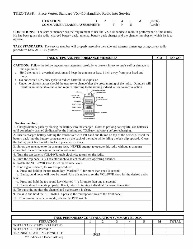
T&EO TASK : Place Vertex Standard VX-410 Handheld Radio into Service
ITERATION: 1 2 3 4 5 M (Circle) COMMANDER/LEADER ASSESSMENT: T P U (Circle)
CONDITIONS: The service member has the requirement to use the VX-410 handheld radio in performance of his duties. He has been given the radio, charged battery pack, antenna, battery pack charger and the channel number on which he is to operate. TASK STANDARDS: The service member will properly assemble the radio and transmit a message using correct radio procedures IAW ACP-125 protocol.
TASK STEPS AND PERFORMANCE MEASURES GO NO-GO CAUTION: Follow the following caution statements carefully to prevent injury to one’s self or damage to
the equipment: a. Hold the radio in a vertical position and keep the antenna at least 1 inch away from your head and
body. b. Do not exceed 50% duty cycle to reduce harmful RF exposure. c. Under no circumstances should the user try to change/alter the programming of the radio. Doing so will
result in an inoperative radio and require returning to the issuing individual for corrective action.
Service member:
1. Charges battery pack by placing the battery into the charger. Note: to prolong battery life, use batteries until completely drained (indicated by the blinking red TX/Busy indicator) before recharging. 2. Inserts charged battery holding the transceiver with left hand and thumb on top of the belt clip. Insert the battery pack into the battery compartment on the back of the radio while titling the belt clip upward. Close the battery pack latch until it locks in place with a click. 3. Screw the antenna onto the antenna jack. NEVER attempt to operate this radio without an antenna connected. Severe damage to the radio will result. 4. Turn the top panel’s VOL/PWR knob clockwise to turn on the radio. 5. Turn the top panel’s CH selector knob to select the desired operating channel. 6. Rotate the VOL/PWR knob to set the volume level. 7. If no signal is heard, follow this procedure: a. Press and hold in the top round key (Marked “-“) for more than one (1) second. b. Background noise will now be heard. Use this noise to set the VOL/PWR knob for the desired audio level. c. Press and hold the top round key (Marked “-“) for more than one (1) second d. Radio should operate properly. If not, return to issuing individual for corrective action. 8. To transmit, monitor the channel and make sure it is clear. 9. Press in and hold the PTT switch. Speak in the microphone area of the front panel. 10. To return to the receive mode, release the PTT switch.
TASK PERFORMANCE / EVALUATION SUMMARY BLOCK ITERATION 1 2 3 4 5 M TOTAL
TOTAL TASK STEPS EVALUATED TOTAL TASK STEPS “GO” TRAINING STATUS “GO”/“NO-GO” “*” indicates a leader task step.

3-24

3-25
T&EO TASK : Place Vertex Standard VXR-7000 Repeater into Service
ITERATION: 1 2 3 4 5 M (Circle) COMMANDER/LEADER ASSESSMENT: T P U (Circle)
CONDITIONS: The communications team has the mission to place the VXR-1000 repeater into service to support field operations. The team has been given a repeater, necessary accessories, coax cable, grounding cable and stakes, antenna, antenna base, and access to a power supply. The team has been given the communications CEOI for the mission. TASK STANDARDS: The communications team will within 1 and ½ hours’ time have the repeater installed and handling operational message traffic.
TASK STEPS AND PERFORMANCE MEASURES GO NO-GO CAUTION: Follow the following caution statements carefully to prevent injury to
one’s self or damage to the equipment: a. Use extreme care in siting the antennas so as to be 2 times the antenna height away from
energized power lines. b. All equipment must be grounded to an earth ground IAW SOP. c. Use only”N” coax connecters/or adapters between the antennas and the repeater.
Attempting to use a PL-259 connector will damage the repeater and antenna.
Task Steps- Setup *1. Site antennas giving consideration to antenna cable length, location of power sources, and shelter. Make sure that the antenna is two times its length away from any power lines. Separate the receiving and transmitting antennas as far apart as possible. 2. Erect antenna masts, attaching the antenna. Erecting the antennas as high as possible will ensure maximum effectiveness from the system. 3. Connect the coax cable between the receiving antenna and repeater connecter marked “TX” (#2 on the rear panel drawing). Note: A “N” type connecter is required between the coax cable the repeater. Note: Duplexers have been installed in all UHF repeaters. Only one antenna is required for operation. 5. Connect the ground wire between a good earth ground and repeater connecter marked “GND” (#6 on the rear panel drawing). 6. Connect the microphone to connector #3 on the front panel.

3-26
TASK STEPS AND PERFORMANCE MEASURES GO NO-GO 7. Connect the power source to the receiver. a. DC (12v, 55Ah) power: Connect the battery leads (observe polarity) to the connector 8 on the rear panel. Note: 1. A small trickle current is present at these terminals to maintain battery charge when operating from AC current. Do not short these terminals. 2. Connecting a 12v battery while using 120v as the primary source will allow repeater operations to continue for a short time in cases of power outages. b. AC (120v), Use the issued power cable to connect connector 7 (rear panel) to the 120v source. Task Steps- Operation 1. Turn on the repeater by pressing Switch #1 on front panel. 2. Set the repeater /base mode. Pressing Switch #4 on front panel allows the repeater to be used as a transceiver using the microphone. For normal operation press switch #4 so the green LED is on, indicating it is in “Repeater Mode”. 3. Press switch #5 until the green lite is OFF. Equipment to use this feature is not installed in the repeater. 4. Press switch #6 to set the squelch mode. When the green light is off, “tone” or “Coded” squelch is active. When you press switch #6 momentarily the green LED will glow steadily and any signal present on the channel will be heard. If you press and hold the switch for more than two (2) seconds, background noise will be heard if no signal is present. 5. Switch #7 is not used. 6. Set volume (Knob #8) to desired level. If repeater monitoring is not desired,
turn fully counter clockwise 7. Set Squelch (Knob #9) to the desired squelch threshold. 8. Push Channel Selector buttons (#10) to select the required operating channel. Repeater should be operational. Note: Do NOT attempt to change or alter the internal programming of the
repeater.
“*” indicates a leader task step.
TASK PERFORMANCE / EVALUATION SUMMARY BLOCK ITERATION 1 2 3 4 5 M TOTAL
TOTAL TASK STEPS EVALUATED TOTAL TASK STEPS “GO” TRAINING STATUS “GO”/“NO-GO”
3-27
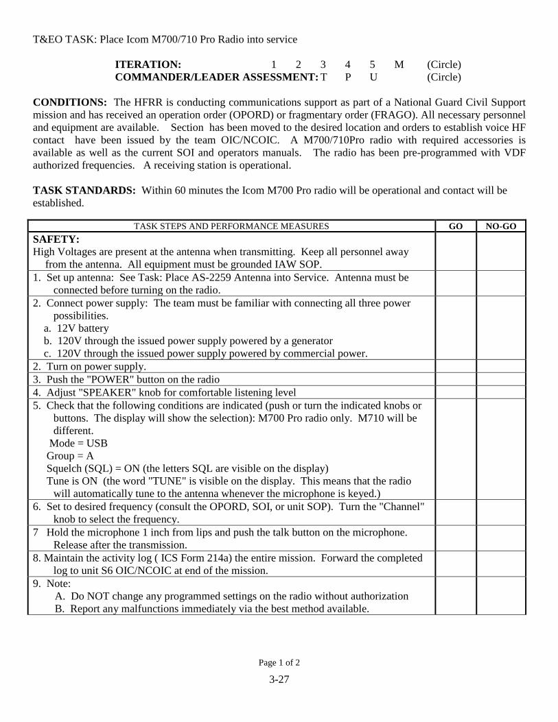
T&EO TASK: Place Icom M700/710 Pro Radio into service
ITERATION: 1 2 3 4 5 M (Circle) COMMANDER/LEADER ASSESSMENT: T P U (Circle)
CONDITIONS: The HFRR is conducting communications support as part of a National Guard Civil Support mission and has received an operation order (OPORD) or fragmentary order (FRAGO). All necessary personnel and equipment are available. Section has been moved to the desired location and orders to establish voice HF contact have been issued by the team OIC/NCOIC. A M700/710Pro radio with required accessories is available as well as the current SOI and operators manuals. The radio has been pre-programmed with VDF authorized frequencies. A receiving station is operational. TASK STANDARDS: Within 60 minutes the Icom M700 Pro radio will be operational and contact will be established.
TASK STEPS AND PERFORMANCE MEASURES GO NO-GO SAFETY: High Voltages are present at the antenna when transmitting. Keep all personnel away
from the antenna. All equipment must be grounded IAW SOP.
1. Set up antenna: See Task: Place AS-2259 Antenna into Service. Antenna must be connected before turning on the radio.
2. Connect power supply: The team must be familiar with connecting all three power possibilities.
a. 12V battery b. 120V through the issued power supply powered by a generator c. 120V through the issued power supply powered by commercial power.
2. Turn on power supply. 3. Push the "POWER" button on the radio 4. Adjust "SPEAKER" knob for comfortable listening level 5. Check that the following conditions are indicated (push or turn the indicated knobs or
buttons. The display will show the selection): M700 Pro radio only. M710 will be different.
Mode = USB Group = A Squelch (SQL) = ON (the letters SQL are visible on the display) Tune is ON (the word "TUNE" is visible on the display. This means that the radio
will automatically tune to the antenna whenever the microphone is keyed.)
6. Set to desired frequency (consult the OPORD, SOI, or unit SOP). Turn the "Channel" knob to select the frequency.
7 Hold the microphone 1 inch from lips and push the talk button on the microphone. Release after the transmission.
8. Maintain the activity log ( ICS Form 214a) the entire mission. Forward the completed log to unit S6 OIC/NCOIC at end of the mission.
9. Note: A. Do NOT change any programmed settings on the radio without authorization B. Report any malfunctions immediately via the best method available.
Page 1 of 2
3-28
b
TASK STEPS AND PERFORMANCE MEASURES GO NO-GO 10. To prepare the radio for transport reverse steps. NOTE: Some units have been issued the M710Pro radio. While the radios are virtually
identical, the team must modify the procedures to account for their particular radio.
TASK PERFORMANCE / EVALUATION SUMMARY BLOCK ITERATION 1 2 3 4 5 M TOTAL
TOTAL TASK STEPS EVALUATED TOTAL TASK STEPS “GO” TRAINING STATUS “GO”/“NO-GO” “*” indicates a leader task step.
Page 2 of 2

3-29
T&EO TASK: Place Wouxun KG-UV3X Radio into Service
ITERATION: 1 2 3 4 5 M (Circle) COMMANDER/LEADER ASSESSMENT: T P U (Circle)
CONDITIONS: The service member has the requirement to use the KG-UV3X handheld radio in performance of his duties. He has been given a programmed radio, charged battery pack, antenna, battery pack charger, and the channel number(s) on which he is to operate. TASK STANDARDS: The service member will properly assemble the radio and transmit a message using correct radio procedures IAW ACP-125 protocol.
TASK STEPS AND PERFORMANCE MEASURES GO NO-GO Caution: Following the following caution statements carefully to prevent injury to one’s
self or damage to the equipment. a. Do not exceed 50% duty cycle to reduce harmful RF exposure. b. Hold the radio in a vertical position and keep the antenna at least 1 inch away from
your head and body. c. Under no circumstances should the user try to change/alter the programming of the
radio. Doing so will result in an inoperative radio and require returning the radio to the issuing individual for corrective action.
1. Installs Battery: Match the guides on the bottom of the battery pack with the back side bottom of the radio. Press on the battery (bottom first). It will latch as you press downward on the top of the battery pack. Press down on the side latches and pull out to release the battery pack.
3. Screw in the antenna on top to the radio. Do not overtighten. 3. Turn the Power/Volume switch clockwise to turn on the radio. The radio will display
the battery voltage. If the voltage is 7.4 or less, recharge the battery.
4. Turn the channel selector to the indicated channel. 5. Push the PTT key to transmit and release to listen. Red light indicates transmitting,
green light indicates receiving transmissions.
6. At end of mission, recharge battery and return to issuing individual.
“*” indicates a leader task step.
TASK PERFORMANCE / EVALUATION SUMMARY BLOCK ITERATION 1 2 3 4 5 M TOTAL
TOTAL TASK STEPS EVALUATED TOTAL TASK STEPS “GO” TRAINING STATUS “GO”/“NO-GO”
3-30
T&EO TASK: Place PittPak into Service
ITERATION: 1 2 3 4 5 M (Circle) COMMANDER/LEADER ASSESSMENT: T P U (Circle)
CONDITIONS: The service member has the requirement to use the PittPak as a training medium for the Guard issued TacPak communications system. He has been given a complete PittPak system, programmed Icom M700/710 radio, charged battery, antenna, battery pack charger, and the applicable guard chart. TASK STANDARDS: The service member will properly assemble the PittPak, MiFi, and HF radio and antenna. Without using “shore” power he/she will successfully log onto the WebEOC account using the WiFi device. He/she will also successfully send an HF email message using the Icom IC-M700/710 radio. Note: This T&EO task utilizes several tasks from other systems. Personnel will need to be trained on all the tasks from the applicable systems as indicated.
TASK STEPS AND PERFORMANCE MEASURES GO NO-GO Caution: Following the following caution statements carefully to prevent injury to one’s
self or damage to the equipment. a. Do not exceed 50% duty cycle to reduce harmful RF exposure. b. Follow all safety procedures when erecting the antenna c. Under no circumstances should the user try to change/alter the programming of the radio or computer. Doing so will result in an inoperative radio/or computer and require returning the equipment to the issuing unit for corrective action.
1. Place the cases near where they will be placed into service. Note that the length of the antenna coax and power cord determines the location of the PittPak.
2. Unpack and place the battery power supply (Juicebox), Icom M700/710, printer, computer, and other supplied parts as needed in the desired location.
3. Complete the task “Place Juicebox G2 into Service” 4. Complete the task “Place M700/710 Radio into Service 5. Powerup the laptop. Note: Run laptop off its internal battery until it is drained, then connect to shore power, or the JuiceBox G2 system.
6. Complete the task “Place Verizon MiFi into Service. 7. Make sure the MiFi is turned on and establish internet connection. 8. Use Gmail to send/retrieve information. a. Browse to Gmail.com and log in using the PittPak account user name and password. b. Send test email to another email account as specified by the trainer.
9. Use SKYPE to send Video Conferencing. Note: Usually prior arrangements will have been made to schedule the Skype conference. a. Establish internet connection. b. Select pre-programmed TACPAK account for video call or search for other account. c. Test Conference Call mode. Note: Calls to non-Skype numbers require purchase of Skype credit. This will need to be established beforehand. Unauthorized expenditures will NOT be reimbursed.
10. Complete the task: “Send an HF Email Message using RMS Express /Winlink.” 11. Complete the task: “Use WEBEOC to Obtain or Transfer Operational Information” 12. At end of mission, recharge batteries and return to issuing individual.

3-31
“*” indicates a leader task step.
TASK PERFORMANCE / EVALUATION SUMMARY BLOCK ITERATION 1 2 3 4 5 M TOTAL
TOTAL TASK STEPS EVALUATED TOTAL TASK STEPS “GO” TRAINING STATUS “GO”/“NO-GO”
3-32
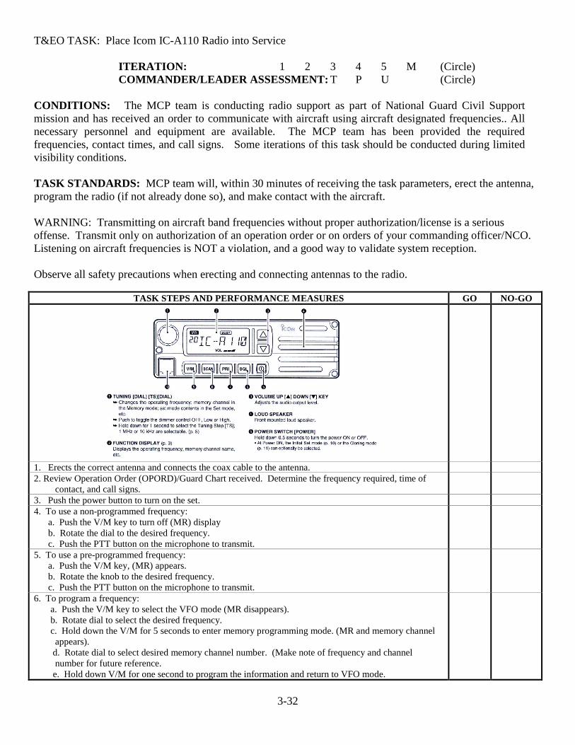
T&EO TASK: Place Icom IC-A110 Radio into Service
ITERATION: 1 2 3 4 5 M (Circle) COMMANDER/LEADER ASSESSMENT: T P U (Circle)
CONDITIONS: The MCP team is conducting radio support as part of National Guard Civil Support mission and has received an order to communicate with aircraft using aircraft designated frequencies.. All necessary personnel and equipment are available. The MCP team has been provided the required frequencies, contact times, and call signs. Some iterations of this task should be conducted during limited visibility conditions. TASK STANDARDS: MCP team will, within 30 minutes of receiving the task parameters, erect the antenna, program the radio (if not already done so), and make contact with the aircraft.
WARNING: Transmitting on aircraft band frequencies without proper authorization/license is a serious offense. Transmit only on authorization of an operation order or on orders of your commanding officer/NCO. Listening on aircraft frequencies is NOT a violation, and a good way to validate system reception.
Observe all safety precautions when erecting and connecting antennas to the radio.
TASK STEPS AND PERFORMANCE MEASURES GO NO-GO
1. Erects the correct antenna and connects the coax cable to the antenna. 2. Review Operation Order (OPORD)/Guard Chart received. Determine the frequency required, time of
contact, and call signs.
3. Push the power button to turn on the set. 4. To use a non-programmed frequency: a. Push the V/M key to turn off (MR) display b. Rotate the dial to the desired frequency. c. Push the PTT button on the microphone to transmit.
5. To use a pre-programmed frequency: a. Push the V/M key, (MR) appears. b. Rotate the knob to the desired frequency. c. Push the PTT button on the microphone to transmit.
6. To program a frequency: a. Push the V/M key to select the VFO mode (MR disappears). b. Rotate dial to select the desired frequency. c. Hold down the V/M for 5 seconds to enter memory programming mode. (MR and memory channel
appears). d. Rotate dial to select desired memory channel number. (Make note of frequency and channel
number for future reference. e. Hold down V/M for one second to program the information and return to VFO mode.

3-33
T&EO TASK: Place Icom IC-A110 Radio into Service
TASK PERFORMANCE / EVALUATION SUMMARY BLOCK ITERATION 1 2 3 4 5 M TOTAL
TOTAL TASK STEPS EVALUATED TOTAL TASK STEPS “GO” TRAINING STATUS “GO”/“NO-GO”
3-34
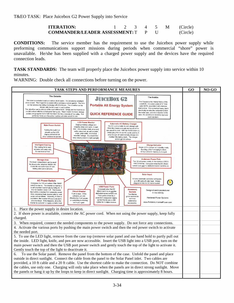
T&EO TASK: Place Juicebox G2 Power Supply into Service
ITERATION: 1 2 3 4 5 M (Circle) COMMANDER/LEADER ASSESSMENT: T P U (Circle)
CONDITIONS: The service member has the requirement to use the Juicebox power supply while preforming communications support missions during periods when commercial “shore” power is unavailable. He/she has been supplied with a charged power supply and the devices have the required connection leads. TASK STANDARDS: The team will properly place the Juicebox power supply into service within 10 minutes. WARNING: Double check all connections before turning on the power.
TASK STEPS AND PERFORMANCE MEASURES GO NO-GO
1. Place the power supply in desire location. 2. If shore power is available, connect the AC power cord. When not using the power supply, keep fully charged.
3. When required, connect the needed components to the power supply. Do not force any connections. 4. Activate the various ports by pushing the main power switch and then the red power switch to activate the needed port.
5. To use the LED light, remove from the case top (remove solar panel and use hand hold to partly pull out the inside. LED light, knife, and pen are now accessible. Insert the USB light into a USB port, turn on the main power switch and then the USB port power switch and gently touch the top of the light to activate it. Gently touch the top of the light to deactivate it.
6. To use the Solar panel. Remove the panel from the bottom of the case. Unfold the panel and place outside in direct sunlight. Connect the cable from the panel to the Solar Panel inlet. Two cables are provided, a 10 ft cable and a 20 ft cable. Use the shortest cable to make the connection. Do NOT combine the cables, use only one. Charging will only take place when the panels are in direct strong sunlight. Move the panels or hang it up by the loops to keep in direct sunlight. Charging time is approximately 8 hours.

3-35
T&EO TASK: Place Juicebox G2 Power Supply into Service
TASK PERFORMANCE / EVALUATION SUMMARY BLOCK ITERATION 1 2 3 4 5 M TOTAL
TOTAL TASK STEPS EVALUATED TOTAL TASK STEPS “GO” TRAINING STATUS “GO”/“NO-GO”

3-36
T&EO TASK: Place Verizon MiFi Device into Service
ITERATION: 1 2 3 4 5 M (Circle) COMMANDER/LEADER ASSESSMENT: T P U (Circle)
CONDITIONS: The service member has the requirement to use the Verizon MiFi communications device while preforming communications support missions with the PittPak. He/she has been supplied with a complete PittPak, a fully charged MiFi device, and a requirement to send an email message via the internet to a specified address . TASK STANDARDS: Service member will, within 15 minutes of receiving the task parameters, connect the device to the laptop, log onto the Gmail system and send the required message. Warning: Do NOT change any settings and passwords set on the MiFi.
TASK STEPS AND PERFORMANCE MEASURES GO NO-GO
1. Assembles the PittPak components per other task sheets. 2. Connects the MiFi to the laptop with the USB cable 3. Push the Power button for 2 seconds to turn on the MiFi 4. Connect to Internet: a. Open the Wi-Fi application on the computer. Select the Jetpack’s WiFi name from
the list of available networks. b. Enter the Wi-Fi password when prompted. c. You are now connected to the internet.
5. Up to 15 devices may be connected via this device. Warning: these devices must be used in support of the mission only.

3-37
T&EO TASK: Place Verizon MiFi Device into Service
TASK PERFORMANCE / EVALUATION SUMMARY BLOCK ITERATION 1 2 3 4 5 M TOTAL
TOTAL TASK STEPS EVALUATED TOTAL TASK STEPS “GO” TRAINING STATUS “GO”/“NO-GO”

3-38
T&EO TASK : Complete DTC Pre-Training Requirements
ITERATION: 1 2 3 4 5 M (Circle) COMMANDER/LEADER ASSESSMENT: T P U (Circle)
CONDITIONS: Personnel have been notified that they are designated as possible VDF vehicle drivers. They have been notified that they must complete the required training to be considered as operational as the designated vehicle driver and/or assistant driver. TASK STANDARDS: The designated personnel will complete the required training and maintain the standard to be considered as deployable for State Active Duty (SAD).
TASK STEPS AND PERFORMANCE MEASURES GO NO-GO 1. Provides, prior to training, a copy of his/her Virginia Driving Record showing zero (0)
points. a. This is obtained free of charge from DMV at: Virginia Department of Motor
Vehicles
b. Just the printout is required for the above. 2. Provides a photocopy of a valid Virginia Driver’s License 3. Completes the DGS Fleet Driver Safety and Policy Lesson on VKO. Turn in a copy of the completion certificate to the testing individual.
“*” indicates a leader task step.
TASK PERFORMANCE / EVALUATION SUMMARY BLOCK ITERATION 1 2 3 4 5 M TOTAL TOTAL TASK STEPS EVALUATED TOTAL TASK STEPS “GO” TRAINING STATUS “GO”/“NO-GO”

3-39
T&EO TASK: Perform Vehicle Preventative Maintenance Checks and Services (PMCS)
ITERATION: 1 2 3 4 5 M (Circle) COMMANDER/LEADER ASSESSMENT: T P U (Circle),,
CONDITIONS: The VDF vehicle driver is conducting support as part of a Mobile Communications Platform (MCP) Direct Support to Civil Authorities mission and has received an operation order (OPORD) or fragmentary order (FRAGO). All necessary personnel and equipment are available. Maintenance records and other applicable records are available.
TASK STANDARDS: The VDF vehicle driver will perform required PMCS before, during, and after motor marches.
TASK STEPS AND PERFORMANCE MEASURES GO NO-GO 1. Reviews vehicle log for the following:
a. Has the last vehicle use been properly entered in the log? b. Were any maintenance issues entered in the log? c. If so, does the log indicate that they have been resolved? d. If maintenance issues are still present, are they mission stoppers? If so, then
immediate action is taken to resolve the issues.
2. Conducts visual inspection of vehicle. a. Are license plates present and with current tags? b. Are the state inspection stickers of both truck and trailer current? c. Is there sufficient tread remaining on the tires? d. Are there any dents/scratches on the truck and trailer bodies which are not noted in
the vehicle log? e. Are the trailer hitch and electrical connections serviceable? f. Are all the glass surfaces clean? g) Battery connections are clean and tight. h) Are trailer wheels chalked while stationary?
3. Conducts Technical Inspection of Truck Systems a. All fluids are checked and up to owner’s manual specifications? 1) Engine Oil 2) Transmission Fluid 3) Windshield Washer 4) Radiator Coolant 5) Are the vehicle tires properly inflated to the recommended pressure? (including
the spare) 6) Are the trailer tires properly inflated to the recommended pressure? (including the
spare) b. Are electrical systems functioning properly? 1) Turn Signals (both truck and trailer) 2) Parking Lights 3) Headlights (High and Low beam) 4) Brake lights (both truck and trailer)
“*” indicates a leader task step.
TASK PERFORMANCE / EVALUATION SUMMARY BLOCK ITERATION 1 2 3 4 5 M TOTAL
TOTAL TASK STEPS EVALUATED TOTAL TASK STEPS “GO” TRAINING STATUS “GO”/“NO-GO”

3-40
T&EO TASK: Perform Vehicle Administrative Functions
ITERATION: 1 2 3 4 5 M (Circle) COMMANDER/LEADER ASSESSMENT: T P U (Circle)
CONDITIONS: The VDF vehicle driver is conducting support as part of a Mobile Communications Platform (MCP) Direct Support to Civil Authorities mission and has received an operation order (OPORD) or fragmentary order (FRAGO). All necessary personnel and equipment are available. Maintenance records and other applicable records are available. This task will be completed in conjunction with the administrative functions of the MCP team, with the vehicle driver being responsible for the administrative functions relating to the vehicle itself. TASK STANDARDS: The VDF vehicle driver will ensure the required administrative functions are completed before, during, and after motor marches.
TASK STEPS AND PERFORMANCE MEASURES GO NO-GO 1. Demonstrate the proper procedure of completing the trip voucher. 2. Demonstrate proper procedure for keeping the vehicle log book up to date. 3. Fuel Card: a) Be able to state the procedure on how to properly use the Fuel Card. b) Be able to state the restrictions on what the Fuel Card cannot be used for. c) Identify the procedure to obtain fuel in event of Fuel Card failure.
4. Accident Reporting: a) Be able state the accident reporting procedure. 1) Stop, render First Aid to all injured parties. 2) Notify local law enforcement immediately. 3) Trade vehicle and driver information with the other vehicle drivers. 4) Up channel SIR report immediately to JFHQ and destination reporting officer. If unable to complete mission, state this in the SIR report. b) Complete Workman’s Compensation Employers First Report of Accident if any injured. c) Complete state vehicle accident report and forward to JFHQ.
5. Paperwork Administration- Be able to state the purpose and use of the following forms. a) SF 91- Motor Vehicle Accident Report b) DD518 Accident ID Card c) MCTS 270- Mileage Log d) Maintenance Log
TASK PERFORMANCE / EVALUATION SUMMARY BLOCK
ITERATION 1 2 3 4 5 M TOTAL TOTAL TASK STEPS EVALUATED TOTAL TASK STEPS “GO” TRAINING STATUS “GO”/“NO-GO” “*” indicates a leader task step.
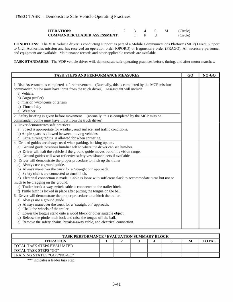
3-41
T&EO TASK: - Demonstrate Safe Vehicle Operating Practices
ITERATION: 1 2 3 4 5 M (Circle) COMMANDER/LEADER ASSESSMENT: T P U (Circle)
CONDITIONS: The VDF vehicle driver is conducting support as part of a Mobile Communications Platform (MCP) Direct Support to Civil Authorities mission and has received an operation order (OPORD) or fragmentary order (FRAGO). All necessary personnel and equipment are available. Maintenance records and other applicable records are available. TASK STANDARDS: The VDF vehicle driver will, demonstrate safe operating practices before, during, and after motor marches.
TASK STEPS AND PERFORMANCE MEASURES GO NO-GO 1. Risk Assessment is completed before movement. (Normally, this is completed by the MCP mission commander, but he must have input from the truck driver). Assessment will include: a) Vehicle. b) Cargo (trailer) c) mission w/concerns of terrain d) Time of day e) Weather 2. Safety briefing is given before movement. (normally, this is completed by the MCP mission commander, but he must have input from the truck driver)
3. Driver demonstrates safe practices. a) Speed is appropriate for weather, road surface, and traffic conditions. b) Ample space is allowed between moving vehicles c) Extra turning radius is allowed for when cornering
4. Ground guides are always used when parking, backing up, etc. a) Ground guide positions him/her self to where the driver can see him/her. b) Driver will halt the vehicle if the ground guide moves out of his vision range. c) Ground guides will wear reflective safety vests/bandoleers if available
5. Driver will demonstrate the proper procedure to hitch up the trailer. a) Always use a ground guide. b) Always maneuver the truck for a “straight on” approach. c) Safety chains are connected to truck hitch. d) Electrical connection is made. Cable is loose with sufficient slack to accommodate turns but not so much to be dragging on the ground. e) Trailer break-a-way switch cable is connected to the trailer hitch. f) Pintle hitch is locked in place after putting the tongue on the ball.
6. Driver will demonstrate the proper procedure to unhitch the trailer. a) Always use a ground guide. b) Always maneuver the truck for a “straight on” approach. c) Chalk the wheels of the trailer. c) Lower the tongue stand onto a wood block or other suitable object. d) Release the pintle hitch lock and raise the tongue off the ball. e) Remove the safety chains, break-a-away cable, and electrical connection.
TASK PERFORMANCE / EVALUATION SUMMARY BLOCK ITERATION 1 2 3 4 5 M TOTAL
TOTAL TASK STEPS EVALUATED TOTAL TASK STEPS “GO” TRAINING STATUS “GO”/“NO-GO” “*” indicates a leader task step.

3-42
T&EO TASK: Plan and Conduct Access Control Operations
ITERATION: 1 2 3 4 5 M (Circle) COMMANDER/LEADER ASSESSMENT: T P U (Circle)
CONDITIONS: The Access Control Resource team is conducting support as part of a National Guard Civil Support mission and has received an operation order (OPORD) or fragmentary order (FRAGO). All necessary personnel and equipment are available. The team has been moved to the duty location and the team OIC/NCOIC has been briefed by proper authorities on the team’s mission. The team has been furnished the current access roster by the facility OIC. TASK STANDARDS: Within 30 minutes VDF Access Control team will be operational.
TASK STEPS AND PERFORMANCE MEASURES
GO NO-GO
SAFETY: Team members must be cognizant that they must be alert at all times while conducting access control operations.
Task Steps: 1. Team leader/NCO conducts a site reconnaissance and determines: a. If and where warning signage will be placed. b. Where team rest area will be. c. Location of fallback position in case of emergencies/unusual situations. d. Operational times of the access control point. e. Scheduled times for relief and subsistence deliveries. f. Insures that reliable communications with higher HQ are in place before activation
of access control point. g. Obtains mission parameters and rules of engagement (ROE) with the civilian
populace (note: written permission must be obtained if locations are on private property)
2. Team leader back briefs incident OIC and obtains authorization to initiate plan. 3. Challenges individuals approaching restricted areas. 3. Checks ID card of all personnel entering the facility. 4. Verifies name against the access roster. 5. Issues facility pass to visitors. 6. If name does not appear on the access roster, contacts the facility activity that the
individual wants to go to and requests an escort from the facility activity.
7. Ensures that the individual signs in on Form 27 (Personnel Register) noting both in and out times.
(note: the facility may use their own form in lieu of Form 27)
8. Provides escort if required by facility SOP. 9. Assures that movement of property being brought into the facility is in accordance
with facility SOP.
10. Checks all outgoing material for misappropriation or theft. 11. Maintain visual check of material entering and exiting facility. 12. Controls property as required. 13. Controls vehicle movement as specified in facility SOP. 14. Collects and issues documents required for vehicle movement. 15. Examines vehicles contents as required by facility SOP

3-43
TASK PERFORMANCE / EVALUATION SUMMARY BLOCK ITERATION 1 2 3 4 5 M TOTAL
TOTAL TASK STEPS EVALUATED TOTAL TASK STEPS “GO” TRAINING STATUS “GO”/“NO-GO”
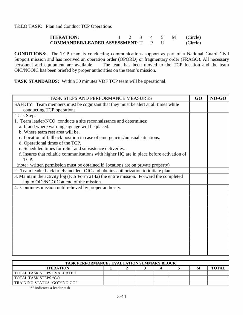
3-44
T&EO TASK: Plan and Conduct TCP Operations
ITERATION: 1 2 3 4 5 M (Circle) COMMANDER/LEADER ASSESSMENT: T P U (Circle)
CONDITIONS: The TCP team is conducting communications support as part of a National Guard Civil Support mission and has received an operation order (OPORD) or fragmentary order (FRAGO). All necessary personnel and equipment are available. The team has been moved to the TCP location and the team OIC/NCOIC has been briefed by proper authorities on the team’s mission. TASK STANDARDS: Within 30 minutes VDF TCP team will be operational.
TASK STEPS AND PERFORMANCE MEASURES GO NO-GO SAFETY: Team members must be cognizant that they must be alert at all times while
conducting TCP operations.
Task Steps: 1. Team leader/NCO conducts a site reconnaissance and determines: a. If and where warning signage will be placed. b. Where team rest area will be. c. Location of fallback position in case of emergencies/unusual situations. d. Operational times of the TCP. e. Scheduled times for relief and subsistence deliveries. f. Insures that reliable communications with higher HQ are in place before activation of
TCP. (note: written permission must be obtained if locations are on private property)
2. Team leader back briefs incident OIC and obtains authorization to initiate plan. 3. Maintain the activity log (ICS Form 214a) the entire mission. Forward the completed
log to OIC/NCOIC at end of the mission.
4. Continues mission until relieved by proper authority.
TASK PERFORMANCE / EVALUATION SUMMARY BLOCK ITERATION 1 2 3 4 5 M TOTAL
TOTAL TASK STEPS EVALUATED TOTAL TASK STEPS “GO” TRAINING STATUS “GO”/“NO-GO” “*” indicates a leader task

A-1
Chapter 4
Situational Training Exercises (STX)
A-2
High Frequency Radio Team Task & Evaluation Outline
1. Purpose: This T&EO booklet will provide the leaders and HFRT team members a concise listing of the currently authorized task lists for this National Guard Civil Support (NGCS) mission. Use of this booklet will also provide unit leaders with a teaching tool as it lists out in a convenient form the necessary tasks required to complete the mission successfully.
2. Changes: The end user is encouraged to submit recommendations for improvement of this T&EO booklet. Please submit the recommendation to HQ, VDF at the Waller Depot address, ATTN: G-6. Please key the suggestions to the specific task as well as the line number of the task step being referenced to.
3. Training: HFRT team leaders should review this T&EO and determine where their team is weak. After the leader review, schedule with the company leader the necessary time in the training schedule to correct the identified deficiencies. It will be necessary to schedule use of the equipment as well because there are more teams than radio sets available.
4. Evaluation: The last T&EO is the Situational Training Exercise (STX) which should be used for the “show down” inspection of the HFRT team. This format will be used by higher headquarters when planning combined teams training MUTA’s. Use of the same format will better prepare your HFRT team for these “show down” inspections as well as for their deployment in an active duty environment.
5. Tasks:
1. Receive Mission and Plan Deployment 2. Draw Required Mission Equipment and Perform PMCS 3. Place Icom M700/710 Pro Radio into Service 4. Place AS-2259 Antenna into Service 5. Perform Radio Station Administrative Functions 6. Place Long Wire Antenna into Service 7. STX Training: Place HF Radio into Service.
6. Changes: Future changes will be indicated on the Division Website with successive editions of this booklet being indicated by their change number and date. If the team leader is in question as to the current T&EO edition he should contact his regimental S6 for determination of the correct edition. 7. Equipment: There are currently two versions of the Icom Marine Pro radio in VDF service, being the M700 and the M710. These radios have few differences between them; however the service members and evaluators should take the model differences into consideration during training and evaluations. Use of other make/model of HF radios should pose no problem after the initial transition training on the use of the different radio.
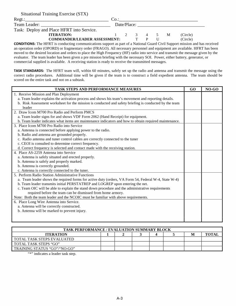
A-3
Situational Training Exercise (STX) Regt.:____________________________________ Co.:__________________________________ Team Leader: ______________________________ Date/Place: _____________________________ Task: Deploy and Place HFRT into Service.
ITERATION: 1 2 3 4 5 M (Circle) COMMANDER/LEADER ASSESSMENT: T P U (Circle)
CONDITIONS: The HFRT is conducting communications support as part of a National Guard Civil Support mission and has received an operation order (OPORD) or fragmentary order (FRAGO). All necessary personnel and equipment are available. HFRT has been moved to the desired location and orders to place the High Frequency (HF) radio into service and transmit the message given by the evaluator. The team leader has been given a pre mission briefing with the necessary SOI. Power, either battery, generator, or commercial supplied is available. A receiving station is ready to receive the transmitted messages. TASK STANDARDS: The HFRT team will, within 60 minutes, safely set up the radio and antenna and transmit the message using the correct radio procedures. Additional time will be given if the team is to construct a field expedient antenna. The team should be scored on the entire task and not on a subtask.
TASK STEPS AND PERFORMANCE MEASURES GO NO-GO 1. Receive Mission and Plan Deployment a. Team leader explains the activation process and shows his team’s movement and reporting details. b. Risk Assessment worksheet for the mission is conducted and safety briefing is conducted by the team
leader
2. Draw Icom M700 Pro Radio and Perform PMCS a. Team leader signs for and shows VDF Form 2062 (Hand Receipt) for equipment. b. Team leader indicates what items are maintenance indicators and how to obtain required maintenance.
3. Place Icom M700 Pro Radio into Service a. Antenna is connected before applying power to the radio. b. Radio and antenna are grounded properly. c. Radio antenna and tuner control cables are correctly connected to the tuner c. CEOI is consulted to determine correct frequency. d. Correct frequency is selected and contact made with the receiving station.
4. Place AS-2259 Antenna into Service a. Antenna is safely situated and erected properly. b. Antenna is safely and properly marked. b. Antenna is correctly grounded. c. Antenna is correctly connected to the tuner.
5. Perform Radio Station Administrative Functions a. Team leader shows the required forms for active duty (orders, VA Form 54, Federal W-4, State W-4) b. Team leader transmits initial PERSTATREP and LOGREP upon entering the net. c. Team OIC will be able to explain the stand down procedure and the administrative requirements
required before the team can be dismissed from home armory. Note: Both the team leader and the NCOIC must be familiar with above requirements.
6. Place Long Wire Antenna into Service. a. Antenna will be correctly constructed. b. Antenna will be marked to prevent injury.
TASK PERFORMANCE / EVALUATION SUMMARY BLOCK ITERATION 1 2 3 4 5 M TOTAL
TOTAL TASK STEPS EVALUATED TOTAL TASK STEPS “GO” TRAINING STATUS “GO”/“NO-GO” “*” indicates a leader task step.
A-4
Incident Management Assistance Team (TACPAK)
Task & Evaluation Outline
1. Purpose: This T&EO booklet will provide to the leaders and IMAT service members a concise listing of the currently authorized task lists for this National Guard Civil Support (NGCS) mission. Use of this booklet will also provide unit leaders with a teaching tool as it lists out in a convenient form the necessary tasks required to complete the mission successfully.
2. Changes: The end user is encouraged to submit recommendations for improvement of this IMAT T&EO booklet. Please submit the recommendation to HQ, VDF at the Waller Depot address, ATTN: G-3. Please key the suggestions to the specific task as well as the line number of the task step being referenced to.
3. Training: IMAT team leaders should review this T&EO and determine where their team is weak. After the leader review, schedule with the MRG leader the necessary time in the training schedule to correct the identified deficiencies. It will be necessary to schedule use of the equipment as well because there are more teams than TACPAK sets available.
4. Evaluation: The last task is the Situational Training Exercise (STX) which should be used for the “show down” inspection of the IMAT team. This format will be used by higher headquarters when planning combined teams training MUTA’s. Use of the same format will better prepare your IMAT team for these “show down” inspections as well as for their deployment in an active duty environment.
5. Tasks:
1. Receive Mission and Plan Deployment 2. Perform IMAT Team administrative functions 3. Draw the TACPAK and Perform PMCS 4. Place TACPAK and Computer into Service 5. Place TACPAK Subsystems into Service 6. Use WEBEOC to Obtain or Transfer Operational Information 7. STX Training: IMAT Team (TACPAK)
6. Changes: Future changes will be indicated on the Division Website with successive editions of this booklet being indicated by their change number and date. If the team leader is in question as to the current METL edition he should contact his regimental S3 for determination of the correct edition. 7. Equipment: There may be different versions of the TACPAK kit issued. The service members and evaluators should take the model differences into consideration during training and evaluations. 8. WebEOC: WebEOC accounts may not be available for routine training situations. If this is the case, an alternate internet web address may be substituted to add realism to the task. In any event, the team must demonstrate knowledge of the necessary requirements and procedures to log on to the website.
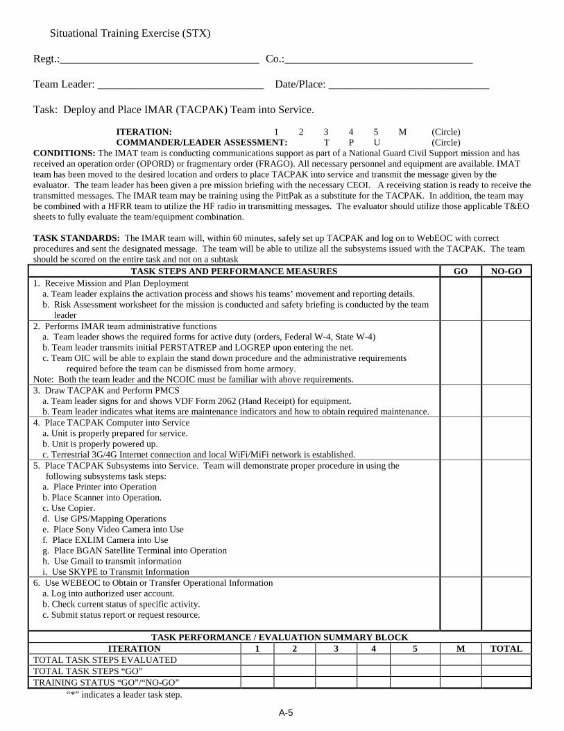
A-5
Situational Training Exercise (STX)
Regt.:____________________________________ Co.:__________________________________ Team Leader: ______________________________ Date/Place: _____________________________
Task: Deploy and Place IMAR (TACPAK) Team into Service.
ITERATION: 1 2 3 4 5 M (Circle) COMMANDER/LEADER ASSESSMENT: T P U (Circle)
CONDITIONS: The IMAT team is conducting communications support as part of a National Guard Civil Support mission and has received an operation order (OPORD) or fragmentary order (FRAGO). All necessary personnel and equipment are available. IMAT team has been moved to the desired location and orders to place TACPAK into service and transmit the message given by the evaluator. The team leader has been given a pre mission briefing with the necessary CEOI. A receiving station is ready to receive the transmitted messages. The IMAR team may be training using the PittPak as a substitute for the TACPAK. In addition, the team may be combined with a HFRR team to utilize the HF radio in transmitting messages. The evaluator should utilize those applicable T&EO sheets to fully evaluate the team/equipment combination. TASK STANDARDS: The IMAR team will, within 60 minutes, safely set up TACPAK and log on to WebEOC with correct procedures and sent the designated message. The team will be able to utilize all the subsystems issued with the TACPAK. The team should be scored on the entire task and not on a subtask
TASK STEPS AND PERFORMANCE MEASURES GO NO-GO 1. Receive Mission and Plan Deployment a. Team leader explains the activation process and shows his teams’ movement and reporting details. b. Risk Assessment worksheet for the mission is conducted and safety briefing is conducted by the team
leader
2. Performs IMAR team administrative functions a. Team leader shows the required forms for active duty (orders, Federal W-4, State W-4) b. Team leader transmits initial PERSTATREP and LOGREP upon entering the net. c. Team OIC will be able to explain the stand down procedure and the administrative requirements
required before the team can be dismissed from home armory. Note: Both the team leader and the NCOIC must be familiar with above requirements.
3. Draw TACPAK and Perform PMCS a. Team leader signs for and shows VDF Form 2062 (Hand Receipt) for equipment. b. Team leader indicates what items are maintenance indicators and how to obtain required maintenance.
4. Place TACPAK Computer into Service a. Unit is properly prepared for service. b. Unit is properly powered up. c. Terrestrial 3G/4G Internet connection and local WiFi/MiFi network is established.
5. Place TACPAK Subsystems into Service. Team will demonstrate proper procedure in using the following subsystems task steps:
a. Place Printer into Operation b. Place Scanner into Operation. c. Use Copier. d. Use GPS/Mapping Operations e. Place Sony Video Camera into Use f. Place EXLIM Camera into Use g. Place BGAN Satellite Terminal into Operation h. Use Gmail to transmit information i. Use SKYPE to Transmit Information
6. Use WEBEOC to Obtain or Transfer Operational Information a. Log into authorized user account. b. Check current status of specific activity. c. Submit status report or request resource.
TASK PERFORMANCE / EVALUATION SUMMARY BLOCK ITERATION 1 2 3 4 5 M TOTAL
TOTAL TASK STEPS EVALUATED TOTAL TASK STEPS “GO” TRAINING STATUS “GO”/“NO-GO” “*” indicates a leader task step.

A-6
Mobile Communications Platform
Training & Evaluation Outline
1. Purpose: This T&EO booklet will provide to the leaders and MCP team service members a concise listing of the currently authorized task lists for this National Guard Civil Support (NGCS) mission. Use of this booklet will also provide unit leaders with a teaching tool as it lists out in a convenient form the necessary tasks required to complete the mission successfully. 2. Changes: The end user is encouraged to submit recommendations for improvement of this MCP T&EO booklet. Please submit the recommendation to HQ, VDF at the Waller Depot address, ATTN: G-6. Please key the suggestions to the specific task as well as the line number of the task step being referenced to. 3. Training: MCP team leaders should review this T&EO and determine where their team is weak. After the leader review, schedule with the MRG leader the necessary time in the training schedule to correct the identified deficiencies. It will be necessary to schedule use of the equipment as well because there are more teams than MCP’s available. 4. Evaluation: The last task is the Situational Training Exercise (STX) which should be used for the “show down” inspection of the MCP team. This format will be used by higher headquarters when planning combined teams training MUTA’s. Use of the same format will better prepare your MCP team for these “show down” inspections as well as for their deployment in an active duty environment.
5. Tasks: 1. Receive Mission and Plan Deployment 2. Draw MCP and Prime Mover 3. Prepare MCP for Operation 4. Perform Generator PMCS 5. Place Generator into Service 6. Place AS-2259 Antenna into Service 7. Place Longwire Antenna into Service 8. Place Lowband VHF Antenna into Service 9. Place Micom 3T radio into Service 10. Place Micom 2e radio into Service 11. Place Kenwood TK690 and TK190 Radios into Service 12. Place Icom IC-A110 Radio into Service 13. Send an HF Email Message using RMS Express 14. Perform Radio Station Administrative Functions 15. Place Micom Secure System into Service 16. Place Vertical Whip Antenna into Service 17. STX Training: Place MCP into Service.
6. Changes: Future changes will be indicated on the Division Website with successive editions of this booklet being indicated by their change number and date. If the team leader is in question as to the current T&EO edition he should contact his regimental S6 for determination of the correct edition. 7. Equipment: In as much as possible, the MCP’s have been equipped identically. However, some differences in equipment and layout will be noted. Team leaders and evaluators should allow for these differences; but the task standards for the equipment that is present should be required to be trained on.
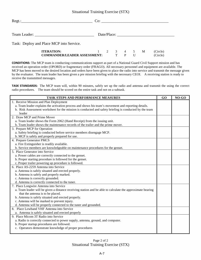
A-7
Situational Training Exercise (STX)
Regt.:____________________________________ Co: __________________________________ Team Leader: ______________________________ Date/Place: _____________________________
Task: Deploy and Place MCP into Service.
ITERATION: 1 2 3 4 5 M (Circle) COMMANDER/LEADER ASSESSMENT: T P U (Circle)
CONDITIONS: The MCP team is conducting communications support as part of a National Guard Civil Support mission and has received an operation order (OPORD) or fragmentary order (FRAGO). All necessary personnel and equipment are available. The MCP has been moved to the desired location and orders have been given to place the radio into service and transmit the message given by the evaluator. The team leader has been given a pre mission briefing with the necessary CEOI. A receiving station is ready to receive the transmitted messages. TASK STANDARDS: The MCP team will, within 90 minutes, safely set up the radio and antenna and transmit the using the correct radio procedures. The team should be scored on the entire task and not on a subtask.
TASK STEPS AND PERFORMANCE MEASURES GO NO-GO 1. Receive Mission and Plan Deployment a. Team leader explains the activation process and shows his team’s movement and reporting details. b. Risk Assessment worksheet for the mission is conducted and safety briefing is conducted by the team
leader
2. Draw MCP and Prime Mover a. Team leader shows the Form 2062 (Hand Receipt) from the issuing unit. b. Team leader shows the maintenance records of the trailer and the prime mover.
3. Prepare MCP for Operation a. Safety briefing is conducted before service members disengage MCP. b. MCP is safely and properly prepared for use.
4. Prepare Generator PMCS a. Fire Extinguisher is readily available. b. Service members are knowledgeable on maintenance procedures for the genset.
5. Place Generator into Service a. Power cables are correctly connected to the genset. b. Proper starting procedure is followed for the genset. c. Proper trailer powering up procedure is followed.
6. Place AS-2259 Antenna into Service a. Antenna is safely situated and erected properly. b. Antenna is safely and properly marked. c. Antenna is correctly grounded. d. Antenna is correctly connected to the tuner.
7. Place Longwire Antenna into Service a. Team leader will be given a distance receiving station and be able to calculate the approximate bearing
that the antenna is to be placed. b. Antenna is safely situated and erected properly. c. Antenna will be marked to prevent injury. d. Antenna will be properly connected to the tuner and grounded.
8. Place Lowband VHF Antenna into Service a. Antenna is safely situated and erected properly
9. Place Micom 3T Radio into Service a. Radio is correctly connected to power supply, antenna, ground, and computer. b. Proper startup procedures are followed. c. Operators demonstrate knowledge of proper procedures
Page 2 of 2
Situational Training Exercise (STX)
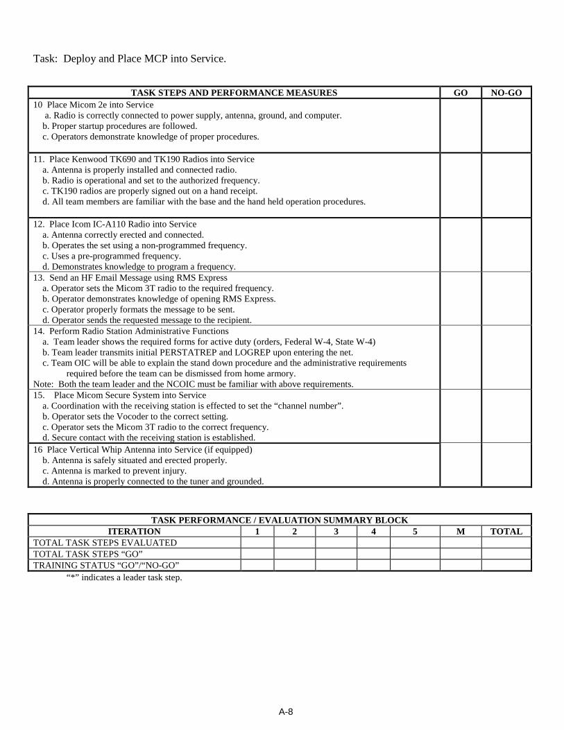
A-8
Task: Deploy and Place MCP into Service.
TASK STEPS AND PERFORMANCE MEASURES GO NO-GO 10 Place Micom 2e into Service a. Radio is correctly connected to power supply, antenna, ground, and computer. b. Proper startup procedures are followed. c. Operators demonstrate knowledge of proper procedures.
11. Place Kenwood TK690 and TK190 Radios into Service a. Antenna is properly installed and connected radio. b. Radio is operational and set to the authorized frequency. c. TK190 radios are properly signed out on a hand receipt. d. All team members are familiar with the base and the hand held operation procedures.
12. Place Icom IC-A110 Radio into Service a. Antenna correctly erected and connected. b. Operates the set using a non-programmed frequency. c. Uses a pre-programmed frequency. d. Demonstrates knowledge to program a frequency.
13. Send an HF Email Message using RMS Express a. Operator sets the Micom 3T radio to the required frequency. b. Operator demonstrates knowledge of opening RMS Express. c. Operator properly formats the message to be sent. d. Operator sends the requested message to the recipient.
14. Perform Radio Station Administrative Functions a. Team leader shows the required forms for active duty (orders, Federal W-4, State W-4) b. Team leader transmits initial PERSTATREP and LOGREP upon entering the net. c. Team OIC will be able to explain the stand down procedure and the administrative requirements
required before the team can be dismissed from home armory. Note: Both the team leader and the NCOIC must be familiar with above requirements.
15. Place Micom Secure System into Service a. Coordination with the receiving station is effected to set the “channel number”. b. Operator sets the Vocoder to the correct setting. c. Operator sets the Micom 3T radio to the correct frequency. d. Secure contact with the receiving station is established.
16 Place Vertical Whip Antenna into Service (if equipped) b. Antenna is safely situated and erected properly. c. Antenna is marked to prevent injury. d. Antenna is properly connected to the tuner and grounded.
TASK PERFORMANCE / EVALUATION SUMMARY BLOCK ITERATION 1 2 3 4 5 M TOTAL
TOTAL TASK STEPS EVALUATED TOTAL TASK STEPS “GO” TRAINING STATUS “GO”/“NO-GO” “*” indicates a leader task step.

A-9
Access Control Resource Task & Evaluation Outline
1. Purpose: This T&EO booklet will provide the leaders and Access Control resource members a concise listing of the currently authorized task lists for this National Guard Civil Support (NGCS) mission. Use of this booklet will also provide unit leaders with a teaching tool as it lists out in a convenient form the necessary tasks required to complete the mission successfully.
2. Changes: The end user is encouraged to submit recommendations for improvement of this T&EO booklet. Please submit the recommendation to HQ, VDF at the Waller Depot address, ATTN: G-3. Please key the suggestions to the specific task as well as the line number of the task step being referenced to.
3. Training: TCP team leaders should review this T&EO and determine where their team is weak. After the leader review, schedule with the MRG leader the necessary time in the training schedule to correct the identified deficiencies. It will be necessary to schedule use of the equipment to ensure that it is available when needed.
4. Evaluation: The last T&EO is the Situational Training Exercise (STX) which should be used for the “show down” inspection of the Access Control Resource team. This format will be used by higher headquarters when planning combined teams training MUTA’s. Use of the same format will better prepare your team for these “show down” inspections as well as for their deployment in an active duty environment.
5. Tasks:
a. Receive Mission and Plan Deployment b. Draw Equipment and perform PMCS c. Plan and Conduct Access Control Operations d. Perform Access Control Resource Administrative Functions e. STX Training: Perform Access Control Duties
6. Changes: Future changes will be indicated on the Division Website with successive editions of this booklet being indicated by their change number and date. If the team leader is in question as to the current T&EO edition he should contact his regimental S6 for determination of the correct edition.
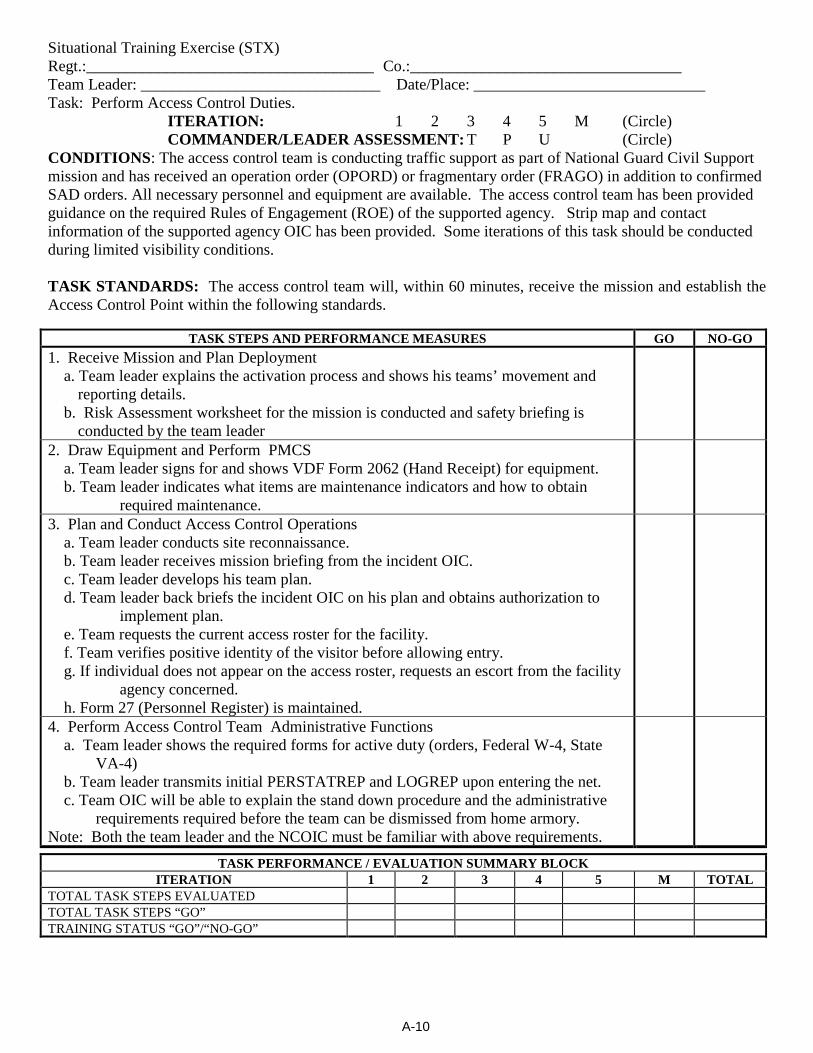
A-10
Situational Training Exercise (STX) Regt.:____________________________________ Co.:__________________________________ Team Leader: ______________________________ Date/Place: _____________________________ Task: Perform Access Control Duties.
ITERATION: 1 2 3 4 5 M (Circle) COMMANDER/LEADER ASSESSMENT: T P U (Circle)
CONDITIONS: The access control team is conducting traffic support as part of National Guard Civil Support mission and has received an operation order (OPORD) or fragmentary order (FRAGO) in addition to confirmed SAD orders. All necessary personnel and equipment are available. The access control team has been provided guidance on the required Rules of Engagement (ROE) of the supported agency. Strip map and contact information of the supported agency OIC has been provided. Some iterations of this task should be conducted during limited visibility conditions. TASK STANDARDS: The access control team will, within 60 minutes, receive the mission and establish the Access Control Point within the following standards.
TASK STEPS AND PERFORMANCE MEASURES GO NO-GO 1. Receive Mission and Plan Deployment a. Team leader explains the activation process and shows his teams’ movement and
reporting details. b. Risk Assessment worksheet for the mission is conducted and safety briefing is
conducted by the team leader
2. Draw Equipment and Perform PMCS a. Team leader signs for and shows VDF Form 2062 (Hand Receipt) for equipment. b. Team leader indicates what items are maintenance indicators and how to obtain
required maintenance.
3. Plan and Conduct Access Control Operations a. Team leader conducts site reconnaissance. b. Team leader receives mission briefing from the incident OIC. c. Team leader develops his team plan. d. Team leader back briefs the incident OIC on his plan and obtains authorization to
implement plan. e. Team requests the current access roster for the facility. f. Team verifies positive identity of the visitor before allowing entry. g. If individual does not appear on the access roster, requests an escort from the facility
agency concerned. h. Form 27 (Personnel Register) is maintained.
4. Perform Access Control Team Administrative Functions a. Team leader shows the required forms for active duty (orders, Federal W-4, State
VA-4) b. Team leader transmits initial PERSTATREP and LOGREP upon entering the net. c. Team OIC will be able to explain the stand down procedure and the administrative
requirements required before the team can be dismissed from home armory. Note: Both the team leader and the NCOIC must be familiar with above requirements.
TASK PERFORMANCE / EVALUATION SUMMARY BLOCK ITERATION 1 2 3 4 5 M TOTAL
TOTAL TASK STEPS EVALUATED TOTAL TASK STEPS “GO” TRAINING STATUS “GO”/“NO-GO”

A-11
Statewide Agency Radio System
(STARS) Radio Team Mission Essential Task List
1. Purpose: This T&EO booklet will provide to the leaders and STARS team members a concise listing of the currently authorized task lists for this National Guard Civil Support (NGCS) mission. Use of this booklet will also provide unit leaders with a teaching tool as it lists out in a convenient form the necessary tasks required to complete the mission successfully.
2. Changes: The end user is encouraged to submit recommendations for improvement of this IMAT T&EO booklet. Please submit the recommendation to HQ, VDF at the Waller Depot address, ATTN: G-3. Please key the suggestions to the specific task as well as the line number of the task step being referenced to.
3. Training: STARS team leaders should review this T&EO and determine where their team is weak. After the leader review, schedule with the MRG leader the necessary time in the training schedule to correct the identified deficiencies. It will be necessary to schedule use of the equipment thru higher headquarters as the actual STARS radios are not an item of VDF issue. Team members may use other available types of radio systems to practice RTO procedures and protocols.
4. Evaluation: The last task is the Situational Training Exercise (STX) which should be used for the “show down” inspection of the STARS team. This format will be used by higher headquarters when planning combined teams training MUTA’s. Use of the same format will better prepare your IMAT team for these “show down” inspections as well as for their deployment in an active duty environment.
5. Tasks:
1. Receive Mission and Plan Deployment 2. Perform STARS Team Administrative Functions 3. Draw the STARS radio and Perform PMCS 4. Place STARS radio into Service 5. STX Training: STARS Team
6. Changes: Future changes will be indicated on the Division Website with successive editions of this booklet being indicated by their change number and date. If the team leader is in question as to the current METL edition he should contact his regimental S3 for determination of the correct edition. 7. Equipment: There may be different versions of the STARS radio issued. The service members and evaluators should take the model differences into consideration during training and evaluations. 8. Important Notice: STARS team members must be cognizant that the radio system they are using is a state wide system being used by several important commonwealth agencies to include law enforcement. Strict adherence to radio protocol (ACP 125, etc.) is required at all times.
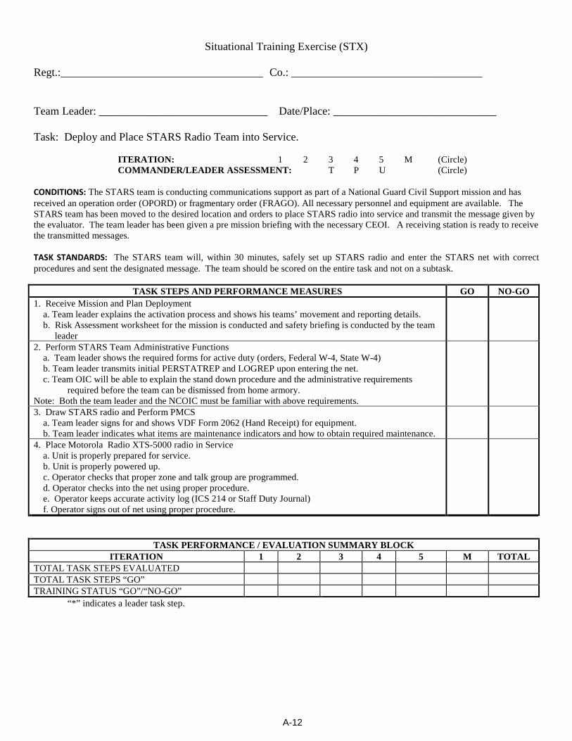
A-12
Situational Training Exercise (STX)
Regt.:____________________________________ Co.: __________________________________ Team Leader: ______________________________ Date/Place: _____________________________
Task: Deploy and Place STARS Radio Team into Service.
ITERATION: 1 2 3 4 5 M (Circle) COMMANDER/LEADER ASSESSMENT: T P U (Circle)
CONDITIONS: The STARS team is conducting communications support as part of a National Guard Civil Support mission and has received an operation order (OPORD) or fragmentary order (FRAGO). All necessary personnel and equipment are available. The STARS team has been moved to the desired location and orders to place STARS radio into service and transmit the message given by the evaluator. The team leader has been given a pre mission briefing with the necessary CEOI. A receiving station is ready to receive the transmitted messages. TASK STANDARDS: The STARS team will, within 30 minutes, safely set up STARS radio and enter the STARS net with correct procedures and sent the designated message. The team should be scored on the entire task and not on a subtask.
TASK STEPS AND PERFORMANCE MEASURES GO NO-GO 1. Receive Mission and Plan Deployment a. Team leader explains the activation process and shows his teams’ movement and reporting details. b. Risk Assessment worksheet for the mission is conducted and safety briefing is conducted by the team
leader
2. Perform STARS Team Administrative Functions a. Team leader shows the required forms for active duty (orders, Federal W-4, State W-4) b. Team leader transmits initial PERSTATREP and LOGREP upon entering the net. c. Team OIC will be able to explain the stand down procedure and the administrative requirements
required before the team can be dismissed from home armory. Note: Both the team leader and the NCOIC must be familiar with above requirements.
3. Draw STARS radio and Perform PMCS a. Team leader signs for and shows VDF Form 2062 (Hand Receipt) for equipment. b. Team leader indicates what items are maintenance indicators and how to obtain required maintenance.
4. Place Motorola Radio XTS-5000 radio in Service a. Unit is properly prepared for service. b. Unit is properly powered up. c. Operator checks that proper zone and talk group are programmed. d. Operator checks into the net using proper procedure. e. Operator keeps accurate activity log (ICS 214 or Staff Duty Journal) f. Operator signs out of net using proper procedure.
TASK PERFORMANCE / EVALUATION SUMMARY BLOCK ITERATION 1 2 3 4 5 M TOTAL
TOTAL TASK STEPS EVALUATED TOTAL TASK STEPS “GO” TRAINING STATUS “GO”/“NO-GO” “*” indicates a leader task step.
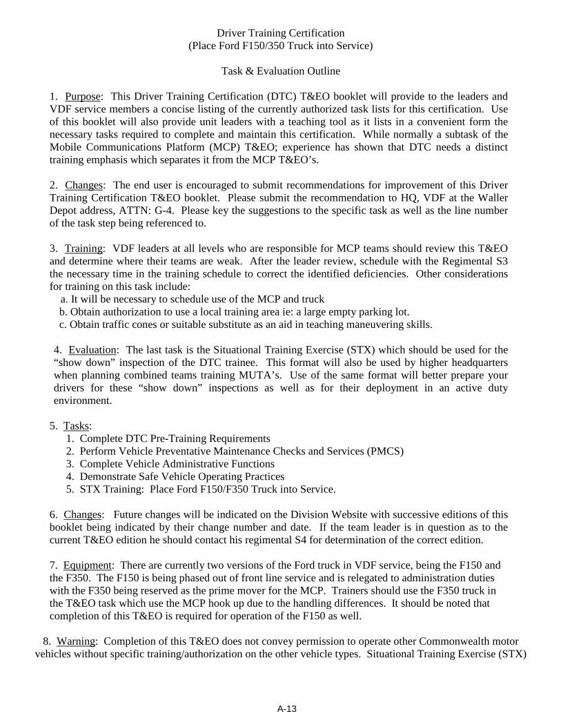
A-13
Driver Training Certification (Place Ford F150/350 Truck into Service)
Task & Evaluation Outline
1. Purpose: This Driver Training Certification (DTC) T&EO booklet will provide to the leaders and VDF service members a concise listing of the currently authorized task lists for this certification. Use of this booklet will also provide unit leaders with a teaching tool as it lists in a convenient form the necessary tasks required to complete and maintain this certification. While normally a subtask of the Mobile Communications Platform (MCP) T&EO; experience has shown that DTC needs a distinct training emphasis which separates it from the MCP T&EO’s.
2. Changes: The end user is encouraged to submit recommendations for improvement of this Driver Training Certification T&EO booklet. Please submit the recommendation to HQ, VDF at the Waller Depot address, ATTN: G-4. Please key the suggestions to the specific task as well as the line number of the task step being referenced to.
3. Training: VDF leaders at all levels who are responsible for MCP teams should review this T&EO and determine where their teams are weak. After the leader review, schedule with the Regimental S3 the necessary time in the training schedule to correct the identified deficiencies. Other considerations for training on this task include: a. It will be necessary to schedule use of the MCP and truck
b. Obtain authorization to use a local training area ie: a large empty parking lot. c. Obtain traffic cones or suitable substitute as an aid in teaching maneuvering skills.
4. Evaluation: The last task is the Situational Training Exercise (STX) which should be used for the “show down” inspection of the DTC trainee. This format will also be used by higher headquarters when planning combined teams training MUTA’s. Use of the same format will better prepare your drivers for these “show down” inspections as well as for their deployment in an active duty environment.
5. Tasks: 1. Complete DTC Pre-Training Requirements
2. Perform Vehicle Preventative Maintenance Checks and Services (PMCS) 3. Complete Vehicle Administrative Functions 4. Demonstrate Safe Vehicle Operating Practices 5. STX Training: Place Ford F150/F350 Truck into Service.
6. Changes: Future changes will be indicated on the Division Website with successive editions of this booklet being indicated by their change number and date. If the team leader is in question as to the current T&EO edition he should contact his regimental S4 for determination of the correct edition. 7. Equipment: There are currently two versions of the Ford truck in VDF service, being the F150 and the F350. The F150 is being phased out of front line service and is relegated to administration duties with the F350 being reserved as the prime mover for the MCP. Trainers should use the F350 truck in the T&EO task which use the MCP hook up due to the handling differences. It should be noted that completion of this T&EO is required for operation of the F150 as well.
8. Warning: Completion of this T&EO does not convey permission to operate other Commonwealth motor vehicles without specific training/authorization on the other vehicle types. Situational Training Exercise (STX)
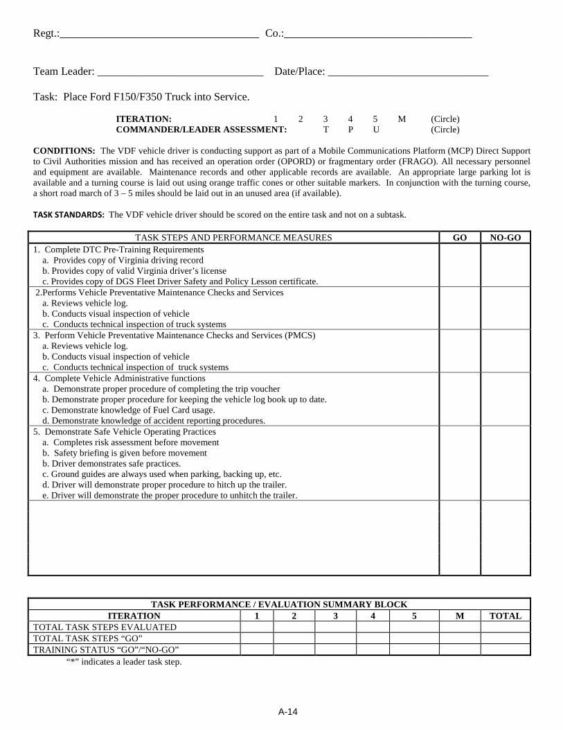
A-14
Regt.:____________________________________ Co.:__________________________________ Team Leader: ______________________________ Date/Place: _____________________________
Task: Place Ford F150/F350 Truck into Service.
ITERATION: 1 2 3 4 5 M (Circle) COMMANDER/LEADER ASSESSMENT: T P U (Circle)
CONDITIONS: The VDF vehicle driver is conducting support as part of a Mobile Communications Platform (MCP) Direct Support to Civil Authorities mission and has received an operation order (OPORD) or fragmentary order (FRAGO). All necessary personnel and equipment are available. Maintenance records and other applicable records are available. An appropriate large parking lot is available and a turning course is laid out using orange traffic cones or other suitable markers. In conjunction with the turning course, a short road march of 3 – 5 miles should be laid out in an unused area (if available). TASK STANDARDS: The VDF vehicle driver should be scored on the entire task and not on a subtask.
TASK STEPS AND PERFORMANCE MEASURES GO NO-GO 1. Complete DTC Pre-Training Requirements a. Provides copy of Virginia driving record b. Provides copy of valid Virginia driver’s license c. Provides copy of DGS Fleet Driver Safety and Policy Lesson certificate.
2.Performs Vehicle Preventative Maintenance Checks and Services a. Reviews vehicle log. b. Conducts visual inspection of vehicle c. Conducts technical inspection of truck systems
3. Perform Vehicle Preventative Maintenance Checks and Services (PMCS) a. Reviews vehicle log. b. Conducts visual inspection of vehicle c. Conducts technical inspection of truck systems
4. Complete Vehicle Administrative functions a. Demonstrate proper procedure of completing the trip voucher b. Demonstrate proper procedure for keeping the vehicle log book up to date. c. Demonstrate knowledge of Fuel Card usage. d. Demonstrate knowledge of accident reporting procedures.
5. Demonstrate Safe Vehicle Operating Practices a. Completes risk assessment before movement b. Safety briefing is given before movement b. Driver demonstrates safe practices. c. Ground guides are always used when parking, backing up, etc. d. Driver will demonstrate proper procedure to hitch up the trailer. e. Driver will demonstrate the proper procedure to unhitch the trailer.
TASK PERFORMANCE / EVALUATION SUMMARY BLOCK ITERATION 1 2 3 4 5 M TOTAL
TOTAL TASK STEPS EVALUATED TOTAL TASK STEPS “GO” TRAINING STATUS “GO”/“NO-GO” “*” indicates a leader task step.
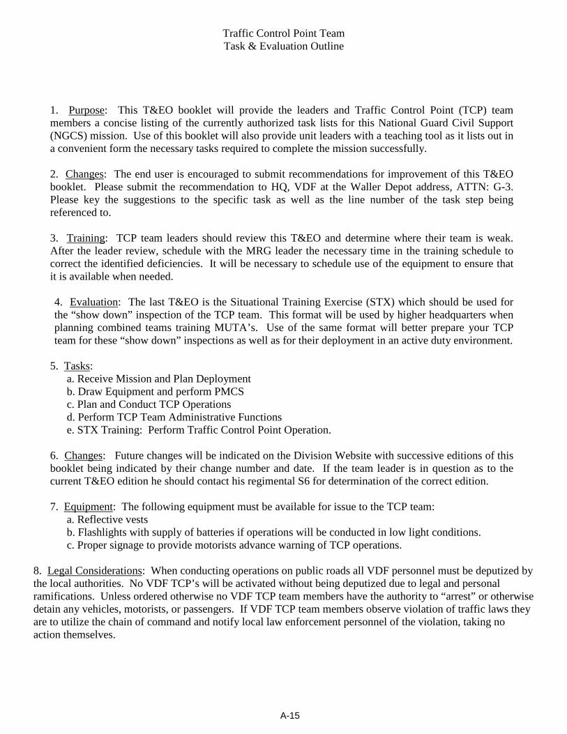
A-15
Traffic Control Point Team Task & Evaluation Outline
1. Purpose: This T&EO booklet will provide the leaders and Traffic Control Point (TCP) team members a concise listing of the currently authorized task lists for this National Guard Civil Support (NGCS) mission. Use of this booklet will also provide unit leaders with a teaching tool as it lists out in a convenient form the necessary tasks required to complete the mission successfully.
2. Changes: The end user is encouraged to submit recommendations for improvement of this T&EO booklet. Please submit the recommendation to HQ, VDF at the Waller Depot address, ATTN: G-3. Please key the suggestions to the specific task as well as the line number of the task step being referenced to.
3. Training: TCP team leaders should review this T&EO and determine where their team is weak. After the leader review, schedule with the MRG leader the necessary time in the training schedule to correct the identified deficiencies. It will be necessary to schedule use of the equipment to ensure that it is available when needed.
4. Evaluation: The last T&EO is the Situational Training Exercise (STX) which should be used for the “show down” inspection of the TCP team. This format will be used by higher headquarters when planning combined teams training MUTA’s. Use of the same format will better prepare your TCP team for these “show down” inspections as well as for their deployment in an active duty environment.
5. Tasks:
a. Receive Mission and Plan Deployment b. Draw Equipment and perform PMCS c. Plan and Conduct TCP Operations d. Perform TCP Team Administrative Functions e. STX Training: Perform Traffic Control Point Operation.
6. Changes: Future changes will be indicated on the Division Website with successive editions of this booklet being indicated by their change number and date. If the team leader is in question as to the current T&EO edition he should contact his regimental S6 for determination of the correct edition. 7. Equipment: The following equipment must be available for issue to the TCP team: a. Reflective vests b. Flashlights with supply of batteries if operations will be conducted in low light conditions. c. Proper signage to provide motorists advance warning of TCP operations.
8. Legal Considerations: When conducting operations on public roads all VDF personnel must be deputized by the local authorities. No VDF TCP’s will be activated without being deputized due to legal and personal ramifications. Unless ordered otherwise no VDF TCP team members have the authority to “arrest” or otherwise detain any vehicles, motorists, or passengers. If VDF TCP team members observe violation of traffic laws they are to utilize the chain of command and notify local law enforcement personnel of the violation, taking no action themselves.
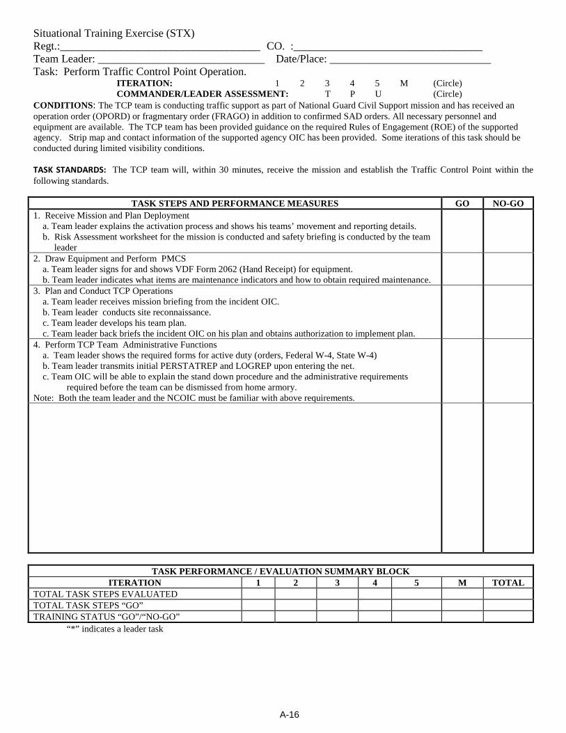
A-16
Situational Training Exercise (STX) Regt.:____________________________________ CO. :__________________________________ Team Leader: ______________________________ Date/Place: _____________________________ Task: Perform Traffic Control Point Operation.
ITERATION: 1 2 3 4 5 M (Circle) COMMANDER/LEADER ASSESSMENT: T P U (Circle)
CONDITIONS: The TCP team is conducting traffic support as part of National Guard Civil Support mission and has received an operation order (OPORD) or fragmentary order (FRAGO) in addition to confirmed SAD orders. All necessary personnel and equipment are available. The TCP team has been provided guidance on the required Rules of Engagement (ROE) of the supported agency. Strip map and contact information of the supported agency OIC has been provided. Some iterations of this task should be conducted during limited visibility conditions.
TASK STANDARDS: The TCP team will, within 30 minutes, receive the mission and establish the Traffic Control Point within the following standards.
TASK STEPS AND PERFORMANCE MEASURES GO NO-GO 1. Receive Mission and Plan Deployment a. Team leader explains the activation process and shows his teams’ movement and reporting details. b. Risk Assessment worksheet for the mission is conducted and safety briefing is conducted by the team
leader
2. Draw Equipment and Perform PMCS a. Team leader signs for and shows VDF Form 2062 (Hand Receipt) for equipment. b. Team leader indicates what items are maintenance indicators and how to obtain required maintenance.
3. Plan and Conduct TCP Operations a. Team leader receives mission briefing from the incident OIC. b. Team leader conducts site reconnaissance. c. Team leader develops his team plan. c. Team leader back briefs the incident OIC on his plan and obtains authorization to implement plan.
4. Perform TCP Team Administrative Functions a. Team leader shows the required forms for active duty (orders, Federal W-4, State W-4) b. Team leader transmits initial PERSTATREP and LOGREP upon entering the net. c. Team OIC will be able to explain the stand down procedure and the administrative requirements
required before the team can be dismissed from home armory. Note: Both the team leader and the NCOIC must be familiar with above requirements.
TASK PERFORMANCE / EVALUATION SUMMARY BLOCK
ITERATION 1 2 3 4 5 M TOTAL TOTAL TASK STEPS EVALUATED TOTAL TASK STEPS “GO” TRAINING STATUS “GO”/“NO-GO” “*” indicates a leader task
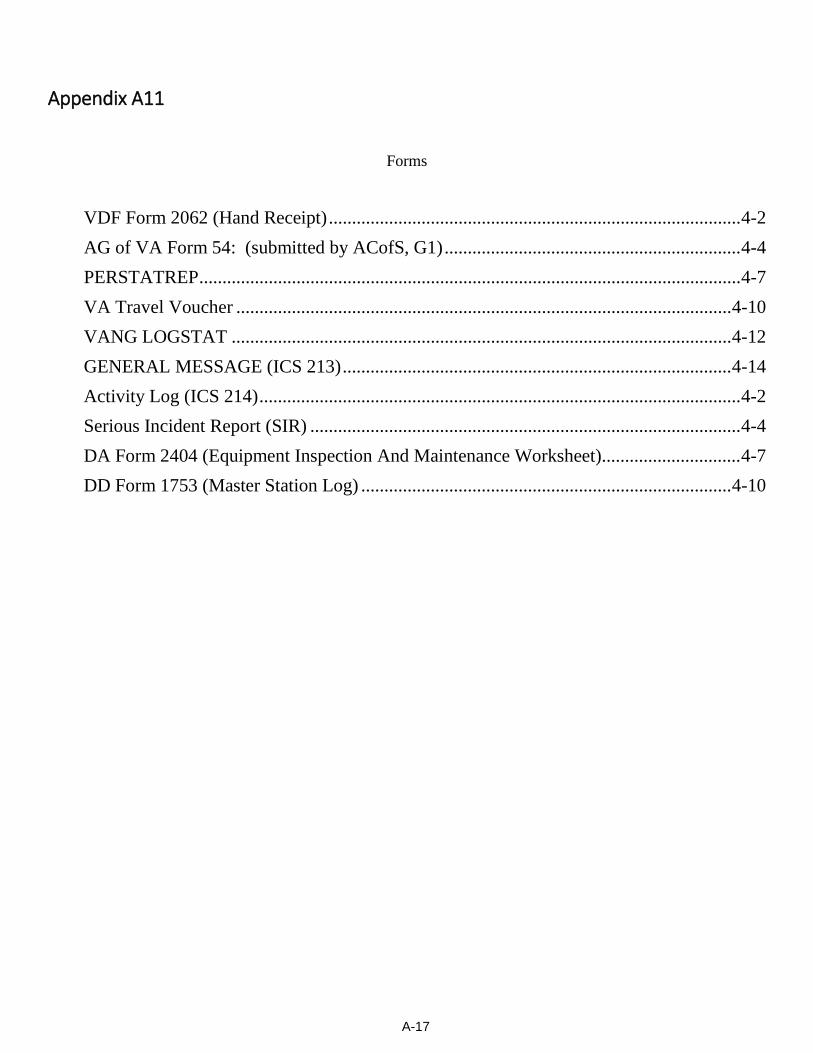
A-17
Appendix A11
Forms
VDF Form 2062 (Hand Receipt) ......................................................................................... 4-2 AG of VA Form 54: (submitted by ACofS, G1) ................................................................ 4-4 PERSTATREP ..................................................................................................................... 4-7 VA Travel Voucher ........................................................................................................... 4-10 VANG LOGSTAT ............................................................................................................ 4-12 GENERAL MESSAGE (ICS 213) .................................................................................... 4-14 Activity Log (ICS 214) ........................................................................................................ 4-2 Serious Incident Report (SIR) ............................................................................................. 4-4 DA Form 2404 (Equipment Inspection And Maintenance Worksheet) .............................. 4-7 DD Form 1753 (Master Station Log) ................................................................................ 4-10
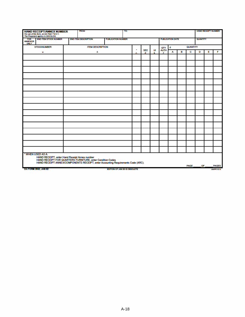
A-18
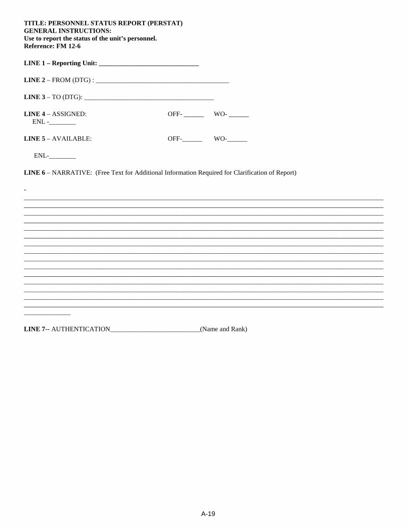
A-19
TITLE: PERSONNEL STATUS REPORT (PERSTAT) GENERAL INSTRUCTIONS: Use to report the status of the unit’s personnel. Reference: FM 12-6
LINE 1 – Reporting Unit: ______________________________
LINE 2 – FROM (DTG) : ________________________________________
LINE 3 – TO (DTG): _______________________________________
LINE 4 – ASSIGNED: OFF- ______ WO- ______ ENL -________
LINE 5 – AVAILABLE: OFF-______ WO-______
ENL-________
LINE 6 – NARRATIVE: (Free Text for Additional Information Required for Clarification of Report)
-__________________________________________________________________________________________________________________________________________________________________________________________________________________________________________________________________________________________________________________________________________________________________________________________________________________________________________________________________________________________________________________________________________________________________________________________________________________________________________________________________________________________________________________________________________________________________________________________________________________________________________________________________________________________________________________________________________________________________________________________________________________________________________________________________________________________________________________________________________________________________________________________________________________________________________________________________________________________________________________________________________________________________________________________________________________________________________________________________________________________________________________________________________________________________________________________________________________________________________________________________________________________________
LINE 7-- AUTHENTICATION___________________________(Name and Rank)
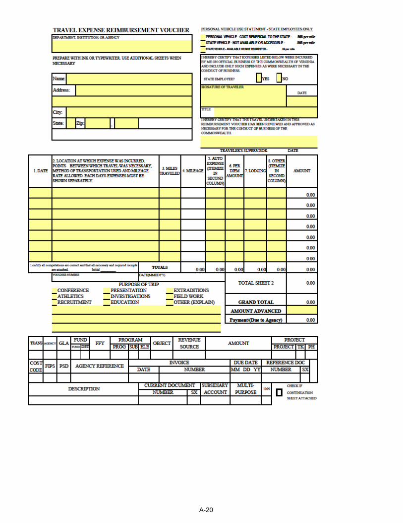
A-20
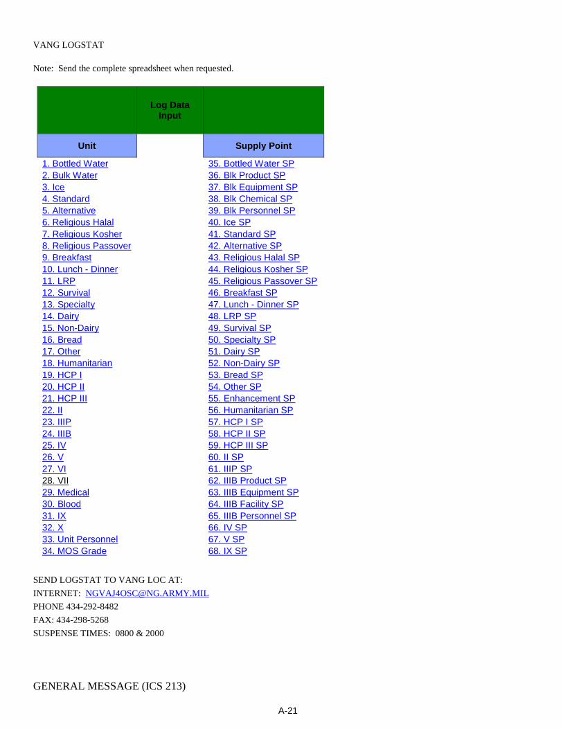
A-21
VANG LOGSTAT
Note: Send the complete spreadsheet when requested.
Log Data Input
Unit
Supply Point
1. Bottled Water
35. Bottled Water SP
2. Bulk Water
36. Blk Product SP
3. Ice
37. Blk Equipment SP
4. Standard
38. Blk Chemical SP
5. Alternative
39. Blk Personnel SP
6. Religious Halal
40. Ice SP
7. Religious Kosher
41. Standard SP
8. Religious Passover
42. Alternative SP
9. Breakfast
43. Religious Halal SP
10. Lunch - Dinner
44. Religious Kosher SP
11. LRP
45. Religious Passover SP
12. Survival
46. Breakfast SP
13. Specialty
47. Lunch - Dinner SP
14. Dairy
48. LRP SP
15. Non-Dairy
49. Survival SP
16. Bread
50. Specialty SP
17. Other
51. Dairy SP
18. Humanitarian
52. Non-Dairy SP
19. HCP I
53. Bread SP
20. HCP II
54. Other SP
21. HCP III
55. Enhancement SP
22. II
56. Humanitarian SP
23. IIIP
57. HCP I SP
24. IIIB
58. HCP II SP
25. IV
59. HCP III SP
26. V
60. II SP
27. VI
61. IIIP SP
28. VII
62. IIIB Product SP
29. Medical
63. IIIB Equipment SP
30. Blood
64. IIIB Facility SP
31. IX
65. IIIB Personnel SP
32. X
66. IV SP
33. Unit Personnel
67. V SP
34. MOS Grade
68. IX SP
SEND LOGSTAT TO VANG LOC AT: INTERNET: [email protected] PHONE 434-292-8482 FAX: 434-298-5268 SUSPENSE TIMES: 0800 & 2000
GENERAL MESSAGE (ICS 213)
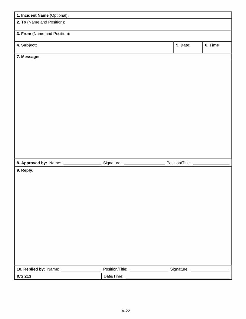
A-22
1. Incident Name (Optional): 2. To (Name and Position): 3. From (Name and Position): 4. Subject:
5. Date:
6. Time
7. Message:
8. Approved by: Name: Signature: Position/Title:
9. Reply:
10. Replied by: Name: Position/Title: Signature:
ICS 213 Date/Time:
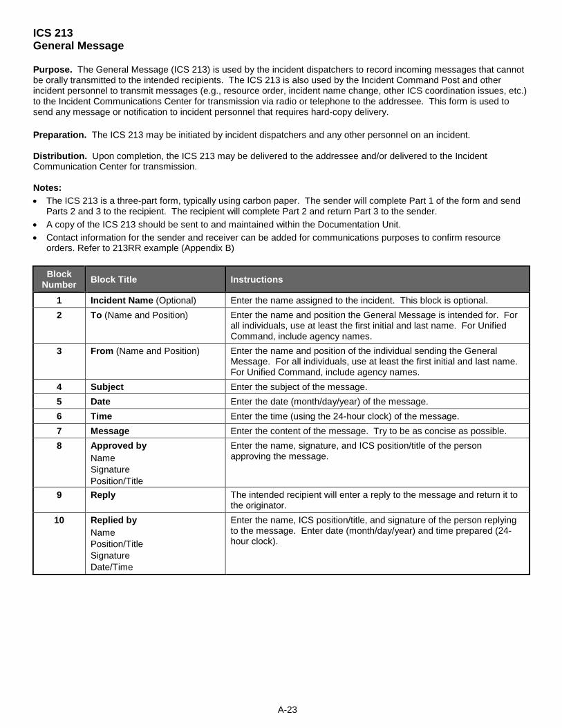
A-23
ICS 213 General Message Purpose. The General Message (ICS 213) is used by the incident dispatchers to record incoming messages that cannot be orally transmitted to the intended recipients. The ICS 213 is also used by the Incident Command Post and other incident personnel to transmit messages (e.g., resource order, incident name change, other ICS coordination issues, etc.) to the Incident Communications Center for transmission via radio or telephone to the addressee. This form is used to send any message or notification to incident personnel that requires hard-copy delivery. Preparation. The ICS 213 may be initiated by incident dispatchers and any other personnel on an incident. Distribution. Upon completion, the ICS 213 may be delivered to the addressee and/or delivered to the Incident Communication Center for transmission. Notes: • The ICS 213 is a three-part form, typically using carbon paper. The sender will complete Part 1 of the form and send
Parts 2 and 3 to the recipient. The recipient will complete Part 2 and return Part 3 to the sender. • A copy of the ICS 213 should be sent to and maintained within the Documentation Unit. • Contact information for the sender and receiver can be added for communications purposes to confirm resource
orders. Refer to 213RR example (Appendix B)
Block Number Block Title Instructions
1 Incident Name (Optional) Enter the name assigned to the incident. This block is optional. 2 To (Name and Position) Enter the name and position the General Message is intended for. For
all individuals, use at least the first initial and last name. For Unified Command, include agency names.
3 From (Name and Position) Enter the name and position of the individual sending the General Message. For all individuals, use at least the first initial and last name. For Unified Command, include agency names.
4 Subject Enter the subject of the message. 5 Date Enter the date (month/day/year) of the message. 6 Time Enter the time (using the 24-hour clock) of the message. 7 Message Enter the content of the message. Try to be as concise as possible. 8 Approved by
Name Signature Position/Title
Enter the name, signature, and ICS position/title of the person approving the message.
9 Reply The intended recipient will enter a reply to the message and return it to the originator.
10 Replied by Name Position/Title Signature Date/Time
Enter the name, ICS position/title, and signature of the person replying to the message. Enter date (month/day/year) and time prepared (24-hour clock).
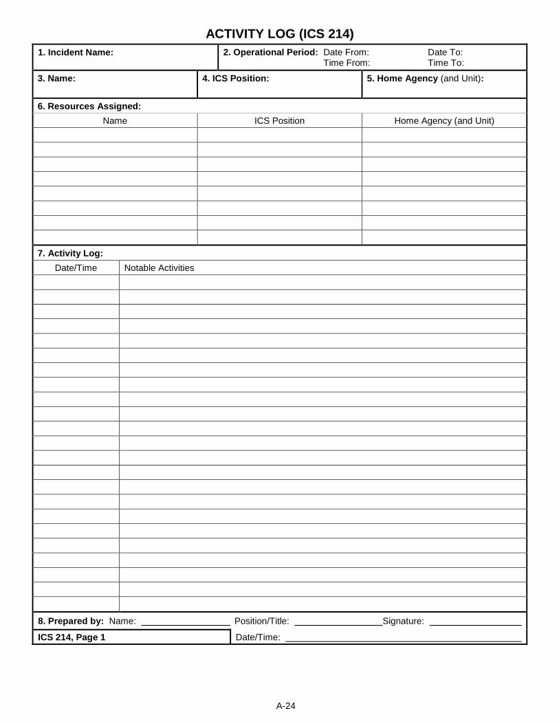
A-24
ACTIVITY LOG (ICS 214) 1. Incident Name: 2. Operational Period: Date From: Date To:
Time From: Time To:
3. Name:
4. ICS Position:
5. Home Agency (and Unit):
6. Resources Assigned: Name ICS Position Home Agency (and Unit)
7. Activity Log: Date/Time Notable Activities
8. Prepared by: Name: Position/Title: Signature:
ICS 214, Page 1 Date/Time:
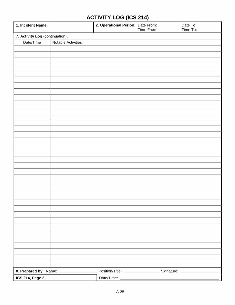
A-25
ACTIVITY LOG (ICS 214) 1. Incident Name: 2. Operational Period: Date From: Date To:
Time From: Time To:
7. Activity Log (continuation): Date/Time Notable Activities
8. Prepared by: Name: Position/Title: Signature:
ICS 214, Page 2 Date/Time:
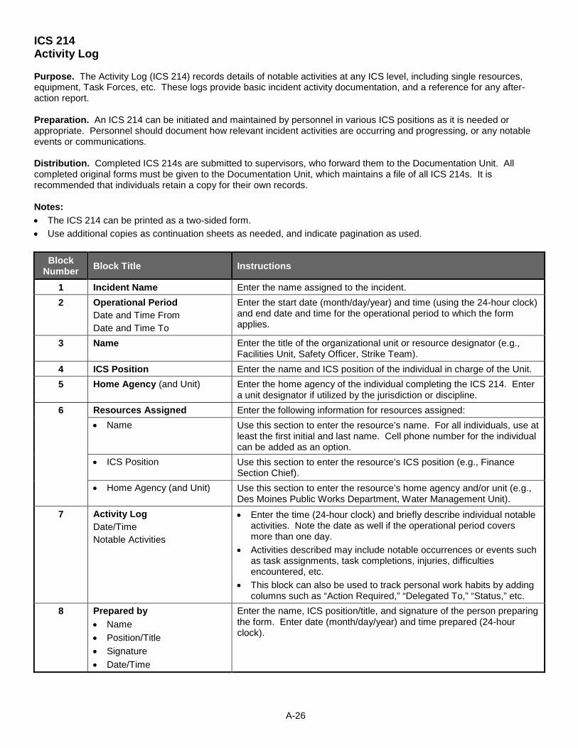
A-26
ICS 214 Activity Log Purpose. The Activity Log (ICS 214) records details of notable activities at any ICS level, including single resources, equipment, Task Forces, etc. These logs provide basic incident activity documentation, and a reference for any after-action report. Preparation. An ICS 214 can be initiated and maintained by personnel in various ICS positions as it is needed or appropriate. Personnel should document how relevant incident activities are occurring and progressing, or any notable events or communications. Distribution. Completed ICS 214s are submitted to supervisors, who forward them to the Documentation Unit. All completed original forms must be given to the Documentation Unit, which maintains a file of all ICS 214s. It is recommended that individuals retain a copy for their own records. Notes: • The ICS 214 can be printed as a two-sided form. • Use additional copies as continuation sheets as needed, and indicate pagination as used.
Block Number Block Title Instructions
1 Incident Name Enter the name assigned to the incident. 2 Operational Period
Date and Time From Date and Time To
Enter the start date (month/day/year) and time (using the 24-hour clock) and end date and time for the operational period to which the form applies.
3 Name Enter the title of the organizational unit or resource designator (e.g., Facilities Unit, Safety Officer, Strike Team).
4 ICS Position Enter the name and ICS position of the individual in charge of the Unit. 5 Home Agency (and Unit) Enter the home agency of the individual completing the ICS 214. Enter
a unit designator if utilized by the jurisdiction or discipline. 6 Resources Assigned Enter the following information for resources assigned:
• Name Use this section to enter the resource’s name. For all individuals, use at least the first initial and last name. Cell phone number for the individual can be added as an option.
• ICS Position Use this section to enter the resource’s ICS position (e.g., Finance Section Chief).
• Home Agency (and Unit) Use this section to enter the resource’s home agency and/or unit (e.g., Des Moines Public Works Department, Water Management Unit).
7 Activity Log Date/Time Notable Activities
• Enter the time (24-hour clock) and briefly describe individual notable activities. Note the date as well if the operational period covers more than one day.
• Activities described may include notable occurrences or events such as task assignments, task completions, injuries, difficulties encountered, etc.
• This block can also be used to track personal work habits by adding columns such as “Action Required,” “Delegated To,” “Status,” etc.
8 Prepared by • Name • Position/Title • Signature • Date/Time
Enter the name, ICS position/title, and signature of the person preparing the form. Enter date (month/day/year) and time prepared (24-hour clock).
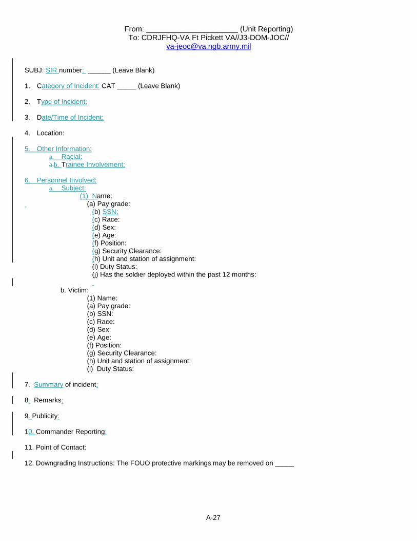
A-27
From: ______________________ (Unit Reporting) To: CDRJFHQ-VA Ft Pickett VA//J3-DOM-JOC//
SUBJ: SIR number: ______ (Leave Blank) 1. Category of Incident: CAT _____ (Leave Blank) 2. Type of Incident: 3. Date/Time of Incident: 4. Location: 5. Other Information:
a. Racial: a.b. Trainee Involvement:
6. Personnel Involved: a. Subject:
(1) Name: (a) Pay grade:
(b) SSN: (c) Race: (d) Sex: (e) Age: (f) Position: (g) Security Clearance: (h) Unit and station of assignment: (i) Duty Status: (j) Has the soldier deployed within the past 12 months:
b. Victim: (1) Name: (a) Pay grade: (b) SSN: (c) Race: (d) Sex: (e) Age: (f) Position: (g) Security Clearance: (h) Unit and station of assignment: (i) Duty Status: 7. Summary of incident: 8. Remarks: 9. Publicity: 10. Commander Reporting: 11. Point of Contact: 12. Downgrading Instructions: The FOUO protective markings may be removed on _____

A-28

A-29
B-1
Glossary
A AC-Alternating Current AP- Assembly Point
B
C C2- Command & Control C3- Command & Conrol & Communications CEOI-Communications Electronics Operating Instructions
D DC- Direct Current DGS- DMA-Department of Military Affairs DMV-Department of Motor Vehicles DTC- Driver Training Certification DTG-Date/Time Group
E
F FRAGO- Fragmentary Order
G GENSET-Generator set GND: Ground GPS-Global Positioning Satellite
H HF-High Frequency HFRR- High Frequency Radio Resource HOR-Home of Record HQ-Head Quarters HS-Home Station
I IAW-In Accordance With ICS-Incident Command System ID-Identfication IMAT- Incident Management Assistance Team
J JFHQ-Joint Forces Head Quarters
K
L LED-Light Emitting Diode LOGREP- Logistics Report LSB-Lower Side Band
M MARS-Military Affiliate Radio System MCP-Mobile Communications Platform

B-2
MSIE- Microsoft Internet Explorer N
NCOIC- Non Commissioned Officer In Charge NGCS- National Guard Civil Support operations NLT-No Later Than NVIS-Near Vertical Incidence Skywave
O OIC-Officer in Charge OPORD- Operations Order
P PERSTATREP- Personnel Status Report PL-259- Metal connector used to connect antenna cables to electronic devices PMCS- Preventative Maintenance Checks & Service PME- Professional Military Education PTT- Push to Talk PWR- Power
Q
R RF-Radio Frequency ROE-Rules of Engagement RX-Receiver
S SAD- State Active Duty SD Card- Small size memory card used in electronic devices SIR-Serious Incident Report SOI- Signal Operating Instructions SOP- Standard Operating Procedure SQL-Squelch STARS- State Agency Radio System STX- Situational Training Exercise
T T&EO-Training & Evaluation Outline TACPAK- Long range communications suite deployed by VDF personnel in support of VANG operations. TCP- Traffic Control Point TM- Training Manual TX-Transmitter
U UHF-Ultra High Frequency USB-Upper Side Band
V V-Volt VANG-Virginia Army National Guard VDEM- Virginia Department of Emergency Management VDF-Virginia Defense Force VHF-Very High Frequency VFO- Variable Frequency Oscilator VKO-Virginia Knowledge Online VOL- Volume
W WARNO- Warning Order

B-3
WebEOC-C2 software utilized by VDEM WLAN-Wireless Local Area Network
X
Y
Z