taper splice method for single-mode fibers
TRANSCRIPT

Taper splice method for single-mode fibers
Akihiko Ishikura, Yasuyuki Kato, and Mitsuru Miyauchi
A low-loss splice method which processes a splice point to a taper shape is investigated for use in subscribersingle-mode fiber cables. An average splice loss, taking into account the fiber parameter deviations andradiation loss in the taper portion, is estimated statistically and experimentally. The optimum value of thetaper ratio is determined to be 0.55. A new processing method for gradual tapers, by pulling fibers andmoving a pair of discharged electrodes, is presented. It is clear that radiation loss due to waveguidemetamorphosis is the dominant cause of taper loss, which is influenced by fiber structures. It is also clear thatthe quick fusion method, with a discharge duration of 1 s, is desirable for the taper splice method. Further-more, it is confirmed that for splicing two fibers having core eccentricities of 1.5 and c0 /im, splice loss can beimproved from 0.4 to 0.25 dB by processing the splice point to a taper shape.
1. Introduction
Various splice methods for single-mode fibers havebeen proposed both theoretically and experimental-ly.'1- In some of these methods, a splice loss of <0.1dB was attained on an average. 5-1" However, becausecore axis misalignment and tilt bring about high spliceloss, these methods have essential handicaps, whichrequire the selection of fibers without core eccentrici-ties,5 a precise core axis alignment mechanism, 7 11 andso on. Core axis alignment mechanisms make splicemachines expensive, while much time is wasted on theprecise core axis alignment. Therefore, these methodsare not suitable for subscriber single-mode fiber opti-cal lines.12 Moreover, they cannot be applied to themass splicing of single-mode fiber ribbons,'3 which willbe introduced in subscriber optical lines in the future.A simple and reliable splice method without core axisalignment which can be applied to subscriber opticalfibers with large core eccentricities is now impatientlyawaited.
This paper describes a taper splice method, whichprocesses the splice point to a taper shape'4 and de-creases splice loss by the relative decrease of misalign-ment and spot size magnification. In the first section,optimum taper parameters are discussed theoretically.Next, a taper process method at a splice point is pre-sented. Then, the cause of splice loss after the taper
The authors are with NTT Ibaraki Electrical Communication Lab-oratories, Tokai, Ibaraki-ken 319-11, Japan.
Received 6 February 1986.0003-6935/86/193460-06$02.00/0.© 1986 Optical Society of America.
process, dependence of taper loss on effective cutoffwavelength and fiber structures, and an optimum fu-sion condition are investigated experimentally.
11. Optimum Taper Structure for Low-Loss Splice
It is known that the mode field spot size is an impor-tant quantity for describing the splice loss of single-mode fibers. The spot size is changed by processing afusion splice point to a gradual taper shape. Spot sizechanges differ with different fiber parameters. Pa-rameters of subscriber single-mode fibers have not yetbeen clarified, so conventional parameters15 for fibersin a 400-Mbit/s transmission system are used in thisinvestigation.
The standardized fiber parameters are shown in thehatched rectangular region in the before-taper processplane in Fig. 1, and the parameter values are listed inTable I. Figure 1 schematically shows changes in thefiber parameters (effective cutoff wavelength and spotsize) at the splice point from before to after the taperprocess. The spot size changes with the taper ratio(Tr), which is the ratio of the taper waist (the narrow-est part of the taper) to the original fiber diameter, arecalculated4 and shown in Fig. 2. Curves a-d corre-spond with points A-D in Fig. 1. From the calcula-tions in Fig. 2, the fiber parameter region, after thetaper process, approaches a parallelogram in shape.To simplify splice loss calculation, three assumptionswere made:
(1) The fiber parameters of the two fibers (P and Q)to be spliced are distributed with uniform probabilityin the optimum fiber-parameter region in Fig. 1.
(2) A maximum core eccentricity e of 1.9 ,gm is per-mitted; it is uniformly distributed in the allowed re-gion.
3460 APPLIED OPTICS / Vol. 25, No. 19 / 1 October 1986

0.2 0.4 0.6TAPER RATIO Tr
SPOT SIZE
Fig. 1. Changes in the fiber-parameter region at splice point beforeand after the taper process.
Table I. Structural Fiber Parameters for the 400-Mbit/s TransmissionSystem
Effectivecutoff
Points in wavelength Spot sizeFig. 1 (Am) (m)
A 1.1 4.5B 1.1 5.5C 1.29 4.5D 1.29 5.5
Fig. 2. Dependence of field spot size on taper ratio.
Spot sizes from Wa to Wd correspond to those in theparallelogram region of the after-taper process planein Fig. 1. To avoid complication of the misalignmentloss calculation, by using an average core misalignmentd, the am is expressed as
f=wb 2a'am = 10 loge 2j 2~,w P(wp)P(wQ)dwpdwQ, (7
where core misalignment is caused by core eccentrici-ties of fibers P and Q, and d is given by
2Eo [E+ - 2epcQ
X cos(Op - Q)]12dEpdeQdOpdOQ,
(3) Core deformation loss and radiation loss causedby the taper shape are disregarded.
Therefore, it is assumed that after the taper process,the fiber parameters are uniformly distributed in theparallelogram region, as shown in Fig. 1.
The transmission coefficient T, of optical power at asplice point with field mismatch and core axis mis-alignment, is given by4
T= 2 wPwQ / -2d 2(1)2T 2exp,
where wp and WQ indicate the spot sizes of the fibers tobe spliced, and d indicates the amount of core axismisalignment. Splice loss a can be described as thesum of field mismatch loss af, and core axis misalign-ment loss am, shown in the (dB) expression below, is
a = -10 log(T) = f + am (dB).
Thus, the average splice loss a is expressed as
a = af + am (dB).
af is given by
_ff-40 log H(-y)dy,
where
H(,y) =W JP(w)P(-yw)dw,WQ
WQW=_
(2)
(3)
(8)
where o = 1.9 m. From the parallelogram assump-tions, the probability density function of the spot sizeis required as follows:
If Wa < Wd,
P(w) =
W -w
(Wa - WC)(Wd - W)
1
Wd -W,
Wb - W
(Wb - Wd)(Wd - W)
0
and if Wa > Wd,
w-w.(Wd - Wc)(Wa - W)
1
P(w) = Wa -Wc| Wb - W
| (Wb - Wa)(Wa - W)
0
(Wc < W < We)
(Wa < W < Wd)
(9a)
(Wd < W < Wb)
(Wb < W),
(W, < W < Wd)
(Wd < W < W)
(9b)
(Wa < W < Wb)
(Wb < W).
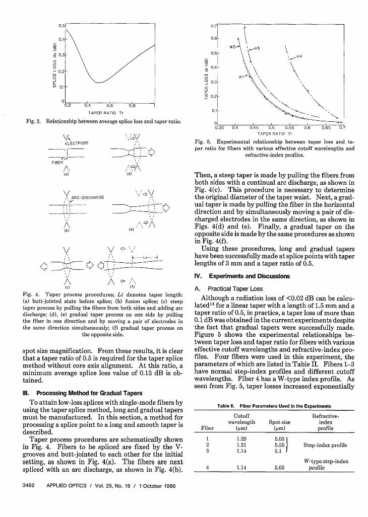
(4) The results of the average splice loss calculations areshown in Fig. 3. The calculated results shown in thefigure indicate that an optimum taper ratio exists andis determined to be 0.5. The average splice loss de-creases in the 1 > Tr > 0.5 range due to relative coremisalignment decrease vs the spot size. In the Tr < 0.5region, the average splice loss increases again due to
(6) the field mismatch, which is caused by the difference of
1 October 1986 / Vol. 25, No. 19 / APPLIED OPTICS 3461
AFTERTAPER PROCESSPLANEI
(Dz
U-
0
to Xcm.
>
w XcminLLU-C)
'U
8
Tr d
/ , W Wd WbI I
C '0'/8EFORETAPER PROCESSPLANE
A' B/ Il ,
w
dC
2.
UJ
0a-
6
4
2
Wmin Wmax w
00.8
nor l l t l
(7)
m
l)Cl)0-J
_Ja-L'
0.7
0.6
0.5
TAPER RATIO Tr
Fig. 3. Relationship between average splice loss and taper ratio.
VIELECTRODE
IFIBER
A(a)
," ARC-DISCHARGE_ _ , '
I, I
A
(b)
1\
"7\(d)
Ce) "
A,FCc) Ci')
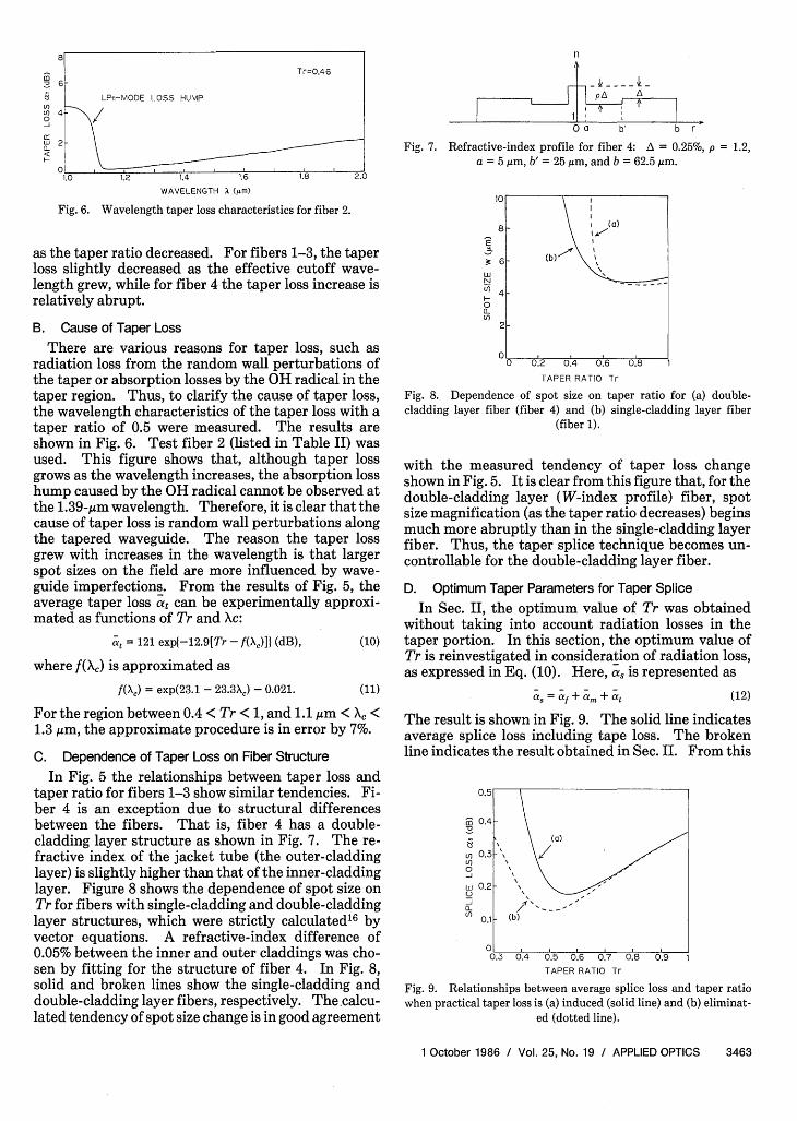
Fig. 4. Taper process procedures; Lt denotes taper length:(a) butt-jointed state before splice; (b) fusion splice; (c) steeptaper process by pulling the fibers from both sides and adding arcdischarge; (d), (e) gradual taper process on one side by pullingthe fiber in one direction and by moving a pair of electrodes inthe same direction simultaneously; (f) gradual taper process on
the opposite side.
spot size magnification. From these results, it is clearthat a taper ratio of 0.5 is required for the taper splicemethod without core axis alignment. At this ratio, aminimum average splice loss value of 0.13 dB is ob-tained.
111. Processing Method for Gradual Tapers
To attain low-loss splices with single-mode fibers byusing the taper splice method, long and gradual tapersmust be manufactured. In this section, a method forprocessing a splice point to a long and smooth taper isdescribed.
Taper process procedures are schematically shownin Fig. 4. Fibers to be spliced are fixed by the V-grooves and butt-jointed to each other for the initialsetting, as shown in Fig. 4(a). The fibers are nextspliced with an arc discharge, as shown in Fig. 4(b).
m
enCl)(
0-J
I0-
0.4L
4fl
0.3 0
0.2' .
0.1-
0.35 0.4 0.45 0.5 0.55 0.6 0.65 0.7TAPER RATIO Tr
Fig. 5. Experimental relationship between taper loss and ta-per ratio for fibers with various effective cutoff wavelengths and
refractive-index profiles.
Then, a steep taper is made by pulling the fibers fromboth sides with a continual arc discharge, as shown inFig. 4(c). This procedure is necessary to determinethe original diameter of the taper waist. Next, a grad-ual taper is made by pulling the fiber in the horizontaldirection and by simultaneously moving a pair of dis-charged electrodes in the same direction, as shown inFigs. 4(d) and (e). Finally, a gradual taper on theopposite side is made by the same procedures as shownin Fig. 4(f).
Using these procedures, long and gradual tapershave been successfully made at splice points with taperlengths of 3 mm and a taper ratio of 0.5.
IV. Experiments and Discussions
A. Practical Taper Loss
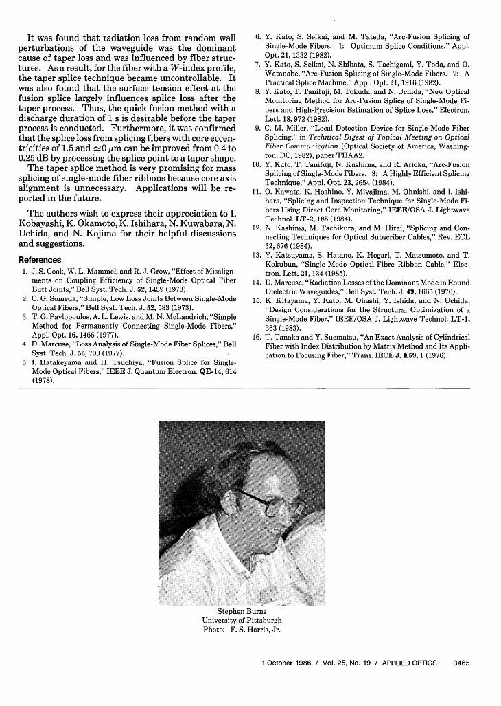
Although a radiation loss of <0.02 dB can be calcu-lated 4 for a linear taper with a length of 1.5 mm and ataper ratio of 0.5, in practice, a taper loss of more than0.1 dB was obtained in the current experiments despitethe fact that gradual tapers were successfully made.Figure 5 shows the experimental relationships be-tween taper loss and taper ratio for fibers with variouseffective cutoff wavelengths and refractive-index pro-files. Four fibers were used in this experiment, theparameters of which are listed in Table II. Fibers 1-3have normal step-index profiles and different cutoffwavelengths. Fiber 4 has a W-type index profile. Asseen from Fig. 5, taper losses increased exponentially
Table II. Fiber Parameters Used in the Experiments
Cutoff Refractive-wavelength Spot size index
Fiber (m) (m) profile
1 1.29 5.052 1.21 5.55 Step-index profile3 1.14 5.1
W-type step-index4 1.14 5.05 profile
3462 APPLIED OPTICS / Vol. 25, No. 19 / 1 October 1986
U)U)0
a-
1.0 1.2 1.4 1.6 1.8
WAVELENGTH X (im)
Fig. 6. Wavelength taper loss characteristics for fiber 2.
as the taper ratio decreased. For fibers 1-3, the taperloss slightly decreased as the effective cutoff wave-length grew, while for fiber 4 the taper loss increase isrelatively abrupt.
B. Cause of Taper Loss
There are various reasons for taper loss, such asradiation loss from the random wall perturbations ofthe taper or absorption losses by the OH radical in thetaper region. Thus, to clarify the cause of taper loss,the wavelength characteristics of the taper loss with ataper ratio of 0.5 were measured. The results areshown in Fig. 6. Test fiber 2 (listed in Table II) wasused. This figure shows that, although taper lossgrows as the wavelength increases, the absorption losshump caused by the OH radical cannot be observed atthe 1.39-/im wavelength. Therefore, it is clear that thecause of taper loss is random wall perturbations alongthe tapered waveguide. The reason the taper lossgrew with increases in the wavelength is that largerspot sizes on the field are more influenced by wave-guide imperfections. From the results of Fig. 5, theaverage taper loss at can be experimentally approxi-mated as functions of Tr and Xc:
at = 121 expl-12.9[Tr - f(X,)] (dB), (10)
where f(Xc) is approximated as
f(X,) = exp(23.1 - 23.3X,) - 0.021. (11)
For the region between 0.4 < Tr < 1, and 1.1 ,gm < X, <1.3 ,um, the approximate procedure is in error by 7%.
C. Dependence of Taper Loss on Fiber Structure
In Fig. 5 the relationships between taper loss andtaper ratio for fibers 1-3 show similar tendencies. Fi-ber 4 is an exception due to structural differencesbetween the fibers. That is, fiber 4 has a double-cladding layer structure as shown in Fig. 7. The re-fractive index of the jacket tube (the outer-claddinglayer) is slightly higher than that of the inner-claddinglayer. Figure 8 shows the dependence of spot size onTr for fibers with single-cladding and double-claddinglayer structures, which were strictly calculatedl6 byvector equations. A refractive-index difference of0.05% between the inner and outer claddings was cho-sen by fitting for the structure of fiber 4. In Fig. 8,solid and broken lines show the single-cladding anddouble-cladding layer fibers, respectively. The calcu-lated tendency of spot size change is in good agreement
n
PA A
a b' b r
Fig. 7. Refractive-index profile for fiber 4: A = 0.25%, p = 1.2,a = 5 um, b' = 25 Am, and b = 62.5,um.
U.
L
N
Cl)
0a-Cl)
TAPER RATIO Tr
Fig. 8. Dependence of spot size on taper ratio for (a) double-cladding layer fiber (fiber 4) and (b) single-cladding layer fiber
(fiber 1).
with the measured tendency of taper loss changeshown in Fig. 5. It is clear from this figure that, for thedouble-cladding layer (W-index profile) fiber, spotsize magnification (as the taper ratio decreases) beginsmuch more abruptly than in the single-cladding layerfiber. Thus, the taper splice technique becomes un-controllable for the double-cladding layer fiber.
D. Optimum Taper Parameters for Taper SpliceIn Sec. II, the optimum value of Tr was obtained
without taking into account radiation losses in thetaper portion. In this section, the optimum value ofTr is reinvestigated in consideration of radiation loss,as expressed in Eq. (10). Here, a, is represented as
a. = a + m + at (12)
The result is shown in Fig. 9. The solid line indicatesaverage splice loss including tape loss. The brokenline indicates the result obtained in Sec. II. From this
m
Cl)U)0-J
C)C)a-u)
U.D
0.4
0.3
0.1
0.5 0.6 0.7 0.8 0.9TAPER RATIO Tr
Fig. 9. Relationships between average splice loss and taper ratiowhen practical taper loss is (a) induced (solid line) and (b) eliminat-
ed (dotted line).
1 October 1986 / Vol. 25, No. 19 / APPLIED OPTICS 3463
eTr=0.46
6
LPii-MODE LOSS HUMP
4
2
/I -
(b)
oL0.3 0.4
I
0.2F

(1) BEFOREFUSION f f i
(2) AFTER SUFFICIENTFUSION
ID
(3) AFTER TAPERPROCESS
(a)
2
m
(2) AFTER QUICK FUSION
(3) AFTER TAPERPROCESS
(b)
°0 0.5 b} 0
0.3-
A0.2 -
0.1 H 0 0.5 1.5 3
DISCHARGE DURATION Td s)
Fig.11. Influence of surface tension effect on splice losses after thetaper process. Stages (1)-(3) indicate the same status as in Fig. 10.
Fig. 10. Schematic views of splice points for the taper process: (a)sufficient fusion method; (b) quick fusion method. Stages (1)-(3)indicate the status before fusion, after fusion, and after-taper pro-
cess, respectively.
figure, the practical optimum value of Tr which mini-mizes the splice loss is found to be 0.55.
E. Optimum Fusion Condition for the Taper Splice Method
Two methods for single-mode fiber splicing havebeen reported. One is the sufficient fusion method,based on the surface tension effect of melted silicawhich reduces misalignment of the fiber axis.5 Anoth-er is the narrow, quick fusion method which reducesthe surface tension effect.6 In this section, the appli-cabilities of the two methods for taper splice are inves-tigated. Figures 10(a) and (b) schematically show thefusion processes for the sufficient fusion method andthe quick fusion method, respectively. Stages (1), (2),and (3) in Fig. 10 show the status before fusion, afterfusion, and after-taper process, respectively. Here,attention should be paid to the longitudinal core defor-mation in the taper portions for both methods. Coredeformation for the sufficient fusion method is gradu-al, while, for the quick fusion method, core deforma-tion is apparently sharp. These core deformationswere observed by a differential-interference-contrastmicroscope.
Figure 11 shows the differences in both methodswith respect to splice loss as a function of dischargeduration Td. Stages (1)-(3) in Fig. 11 show the samesplice status as in Fig. 10. A quick fusion is performedfor the Td < 1.5-s region. The circles in the figurerepresent the mean value of splice loss for ten samples.A test fiber without core eccentricity was used, and aninitial core misalignment of 3 ,im was set in the experi-ment. The figure shows that splice loss after the taperprocess for the quick fusion method is smaller thanthat for the sufficient fusion method, because, for thesufficient fusion method, core deformation after fusionis extended when the taper process is performed.Consequently, the quick fusion method is desirable forthe taper splice, and a discharge duration of 1 s (whichcorresponds to the duration in Ref. 6) was chosen asthe optimum value.
m 2
I
u) 07-° 0.5LUU 0.3J(/0.2
11n
(1) (2) (3)
SPLICE STATUS
Fig. 12. Splice loss change for two fibers with core eccentricities of1.5 and 0 Mm for the splice status stages (1)-(3) which are the same
as in Fig. 10.
Next, two fibers with core eccentricities of 1.5 andc±,0 gim were prepared and spliced together by usingthe optimum discharge condition and the optimumtaper parameters. The results are shown in Fig. 12.Vertical segments represent the range of values fortwelve splices. Splice status stages (1)-(3) are thesame as those in Fig. 11. Average splice loss beforefusion, after fusion, and after-taper process were foundto be 0.79,0.4, and 0.25 dB, respectively. As a result, itwas confirmed that splice loss for fibers with large coreeccentricities can be improved by processing the splicepoint to a taper shape.
V. Conclusion
A low-loss splice method for single-mode fiberswithout core axis alignment has been investigated.This method is based on processing the splice point toa taper shape and improving the coupling efficiency ofoptical power by decreasing core axis misalignment.The average splice loss, taking into account the fiberparameter deviations and radiation loss in the taperportion, has been estimated statistically and experi-mentally. The optimum value of the taper ratio whichminimizes taper loss was determined to be 0.55. A newprocessing method for gradual tapers by pulling fibersand moving a pair of discharged electrodes was pre-sented. Using this technique, gradual tapers weresuccessfully made at splice points with taper lengths of3 mm and a taper ratio of 0.5.
3464 APPLIED OPTICS / Vol. 25, No. 19 / 1 October 1986
(1)
Il
X I
It was found that radiation loss from random wallperturbations of the waveguide was the dominantcause of taper loss and was influenced by fiber struc-tures. As a result, for the fiber with a W-index profile,the taper splice technique became uncontrollable. Itwas also found that the surface tension effect at thefusion splice largely influences splice loss after thetaper process. Thus, the quick fusion method with adischarge duration of 1 s is desirable before the taperprocess is conducted. Furthermore, it was confirmedthat the splice loss from splicing fibers with core eccen-tricities of 1.5 and 0 gim can be improved from 0.4 to0.25 dB by processing the splice point to a taper shape.
The taper splice method is very promising for masssplicing of single-mode fiber ribbons because core axisalignment is unnecessary. Applications will be re-ported in the future.
The authors wish to express their appreciation to I.Kobayashi, K. Okamoto, K. Ishihara, N. Kuwabara, N.Uchida, and N. Kojima for their helpful discussionsand suggestions.
References
1. J. S. Cook, W. L. Mammel, and R. J. Grow, "Effect of Misalign-ments on Coupling Efficiency of Single-Mode Optical FiberButt Joints," Bell Syst. Tech. J. 52, 1439 (1973).
2. C. G. Someda, "Simple, Low Loss Joints Between Single-ModeOptical Fibers," Bell Syst. Tech. J. 52, 583 (1973).
3. T. G. Pavlopoulos, A. L. Lewis, and M. N. McLandrich, "SimpleMethod for Permanently Connecting Single-Mode Fibers,"Appl. Opt. 16, 1466 (1977).
4. D. Marcuse, "Loss Analysis of Single-Mode Fiber Splices," BellSyst. Tech. J. 56, 703 (1977).
5. I. Hatakeyama and H. Tsuchiya, "Fusion Splice for Single-Mode Optical Fibers," IEEE J. Quantum Electron. QE-14, 614(1978).
6. Y. Kato, S. Seikai, and M. Tateda, "Arc-Fusion Splicing ofSingle-Mode Fibers. 1: Optimum Splice Conditions," Appl.Opt. 21, 1332 (1982).
7. Y. Kato, S. Seikai, N. Shibata, S. Tachigami, Y. Toda, and 0.Watanabe, "Arc-Fusion Splicing of Single-Mode Fibers. 2: APractical Splice Machine," Appl. Opt. 21, 1916 (1982).
8. Y. Kato, T. Tanifuji, M. Tokuda, and N. Uchida, "New OpticalMonitoring Method for Arc-Fusion Splice of Single-Mode Fi-bers and High-Precision Estimation of Splice Loss," Electron.Lett. 18, 972 (1982).
9. C. M. Miller, "Local Detection Device for Single-Mode FiberSplicing," in Technical Digest of Topical Meeting on OpticalFiber Communication (Optical Society of America, Washing-ton, DC, 1982), paper THAA2.
10. Y. Kato, T. Tanifuji, N. Kashima, and R. Arioka, "Arc-FusionSplicing of Single-Mode Fibers. 3: A Highly Efficient SplicingTechnique," Appl. Opt. 23, 2654 (1984).
11. 0. Kawata, K. Hoshino, Y. Miyajima, M. Ohnishi, and I. Ishi-hara, "Splicing and Inspection Technique for Single-Mode Fi-bers Using Direct Core Monitoring," IEEE/OSA J. LightwaveTechnol. LT-2, 185 (1984).
12. N. Kashima, M. Tachikura, and M. Hirai, "Splicing and Con-necting Techniques for Optical Subscriber Cables," Rev. ECL32, 676 (1984).
13. Y. Katsuyama, S. Hatano, K. Hogari, T. Matsumoto, and T.Kokubun, "Single-Mode Optical-Fibre Ribbon Cable," Elec-tron. Lett. 21, 134 (1985).
14. D. Marcuse, "Radiation Losses of the Dominant Mode in RoundDielectric Waveguides," Bell Syst. Tech. J. 49, 1665 (1970).
15. K. Kitayama, Y. Kato, M. Ohashi, Y. Ishida, and N. Uchida,"Design Considerations for the Structural Optimization of aSingle-Mode Fiber," IEEE/OSA J. Lightwave Technol. LT-1,363 (1983).
16. T. Tanaka and Y. Suematsu, "An Exact Analysis of CylindricalFiber with Index Distribution by Matrix Method and Its Appli-cation to Focusing Fiber," Trans. IECE J. E59, 1 (1976).
Stephen BurnsUniversity of PittsburghPhoto: F. S. Harris, Jr.
1 October 1986 / Vol. 25, No. 19 / APPLIED OPTICS 3465