tankless gas water heaters -
TRANSCRIPT

R
Tankless Gas Water Heaters
High Effi ciency Condensing ModelsPHH-25ROFN & PHH-32ROFN (Outdoor Natural Gas Models)PHH-25ROFP & PHH-32ROFP (Outdoor L.P. Gas Models)PHH-25RDVN & PHH-32RDVN (Indoor Direct Vent Natural Gas Models)PHH-25RDVP & PHH-32RDVP (Indoor Direct Vent L.P. Gas Models)
Engineering Handbook
DESIGN
CERTIFIED ®
CERTIFIED
R
Mid Effi ciency ModelsPH2-20R OFN, PH2-25R OFN & PH2-28R OFN (Outdoor Natural Gas Models)PH2-20R OFP, PH2-25R OFP & PH2-28R OFP (Outdoor L.P. Gas Models)PH2-20R DVSN, PH2-25R DVSN & PH2-28R DVSN(Indoor Direct Vent Natural Gas Models)PH2-20R DVSP, PH2-25R DVSP & PH2-28R DVSP(Indoor Direct Vent L.P. Gas Models)
Outdoor Water HeaterPH2-20, 25 & 28ROF Indoor Direct Vent Water Heater
PH2-20, 25 & 28RDVS
Outdoor Water HeaterPHH-25ROF & PHH-32ROF
Indoor Direct Vent Water HeaterPHH-25RDV & PHH-32RDV
2 | Page SVC 820 Tankless Gas Trouble Shooting Manual
2
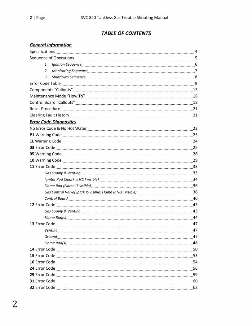
TABLE OF CONTENTS
General Information Specifications 4 Sequence of Operations 5
1. Ignition Sequence 6 2. Monitoring Sequence 7 3. Shutdown Sequence 8
Error Code Table 9 Components “Callouts” 15 Maintenance Mode “How To” 16 Control Board “Callouts” 18 Reset Procedure 21 Clearing Fault History 21
Error Code Diagnostics No Error Code & No Hot Water 22 P1 Warning Code 23 1L Warning Code 24 03 Error Code 25 05 Warning Code 26 10 Warning Code 29 11 Error Code 33 Gas Supply & Venting 33 Igniter Rod (Spark is NOT visible) 34
Flame Rod (Flame IS visible) 36
Gas Control Valve (Spark IS visible; Flame is NOT visible) 38
Control Board 40
12 Error Code 43 Gas Supply & Venting 43 Flame Rod(s) 44 13 Error Code 47 Venting 47 Ground 47 Flame Rod(s) 48 14 Error Code 50 15 Error Code 53 16 Error Code 54 24 Error Code 56 29 Error Code 59 31 Error Code 60 32 Error Code 62
SVC 820-Tankless Gas Trouble Shooting Manual Page | 3
3
TABLE OF CONTENTS
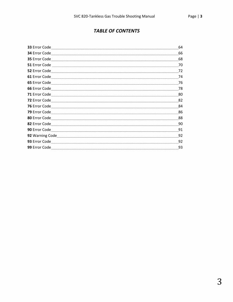
33 Error Code 64 34 Error Code 66 35 Error Code 68 51 Error Code 70 52 Error Code 72 61 Error Code 74 65 Error Code 76 66 Error Code 78 71 Error Code 80 72 Error Code 82 76 Error Code 84 79 Error Code 86 80 Error Code 88 82 Error Code 90 90 Error Code 91 92 Warning Code 92 93 Error Code 92 99 Error Code 93
4 | Page SVC 820 Tankless Gas Trouble Shooting Manual
4
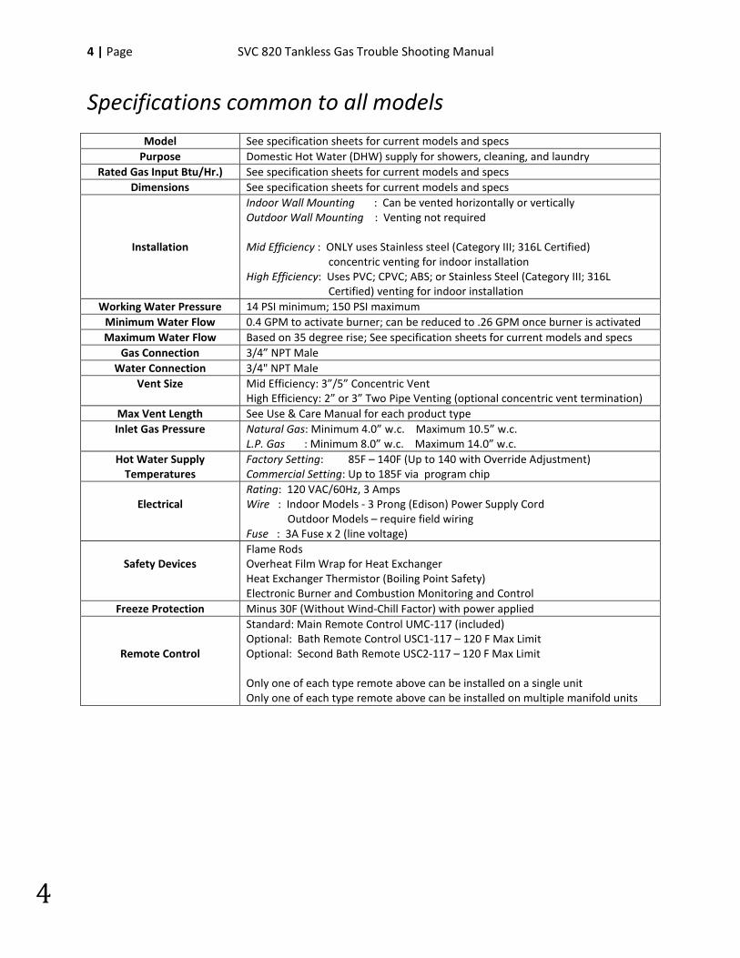
Specifications common to all models
Model See specification sheets for current models and specs Purpose Domestic Hot Water (DHW) supply for showers, cleaning, and laundry
Rated Gas Input Btu/Hr.) See specification sheets for current models and specs Dimensions See specification sheets for current models and specs
Installation
Indoor Wall Mounting : Can be vented horizontally or vertically Outdoor Wall Mounting : Venting not required Mid Efficiency : ONLY uses Stainless steel (Category III; 316L Certified) concentric venting for indoor installation High Efficiency: Uses PVC; CPVC; ABS; or Stainless Steel (Category III; 316L Certified) venting for indoor installation
Working Water Pressure 14 PSI minimum; 150 PSI maximum Minimum Water Flow 0.4 GPM to activate burner; can be reduced to .26 GPM once burner is activated Maximum Water Flow Based on 35 degree rise; See specification sheets for current models and specs
Gas Connection 3/4” NPT Male Water Connection 3/4" NPT Male
Vent Size Mid Efficiency: 3”/5” Concentric Vent High Efficiency: 2” or 3” Two Pipe Venting (optional concentric vent termination)
Max Vent Length See Use & Care Manual for each product type Inlet Gas Pressure Natural Gas: Minimum 4.0” w.c. Maximum 10.5” w.c.
L.P. Gas : Minimum 8.0” w.c. Maximum 14.0” w.c. Hot Water Supply
Temperatures Factory Setting: 85F – 140F (Up to 140 with Override Adjustment) Commercial Setting: Up to 185F via program chip
Electrical
Rating: 120 VAC/60Hz, 3 Amps Wire : Indoor Models - 3 Prong (Edison) Power Supply Cord Outdoor Models – require field wiring Fuse : 3A Fuse x 2 (line voltage)
Safety Devices
Flame Rods Overheat Film Wrap for Heat Exchanger Heat Exchanger Thermistor (Boiling Point Safety) Electronic Burner and Combustion Monitoring and Control
Freeze Protection Minus 30F (Without Wind-Chill Factor) with power applied
Remote Control
Standard: Main Remote Control UMC-117 (included) Optional: Bath Remote Control USC1-117 – 120 F Max Limit Optional: Second Bath Remote USC2-117 – 120 F Max Limit Only one of each type remote above can be installed on a single unit Only one of each type remote above can be installed on multiple manifold units
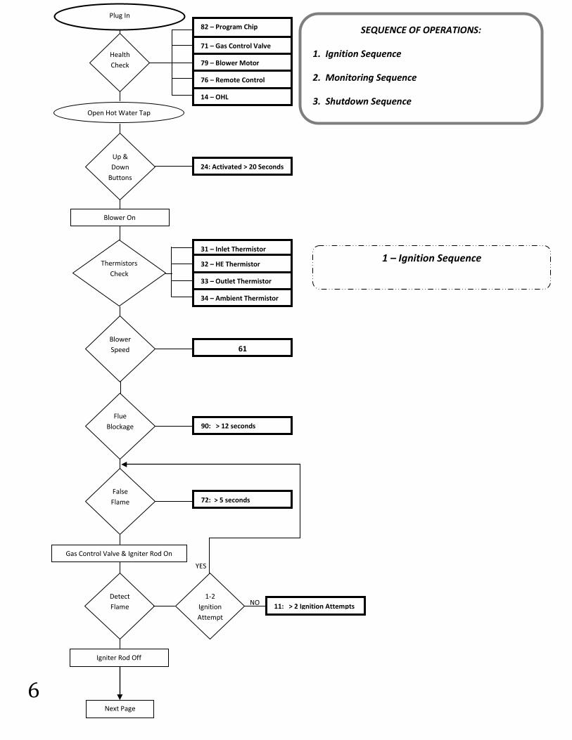
SVC 820-Tankless Gas Trouble Shooting Manual Page | 5
5
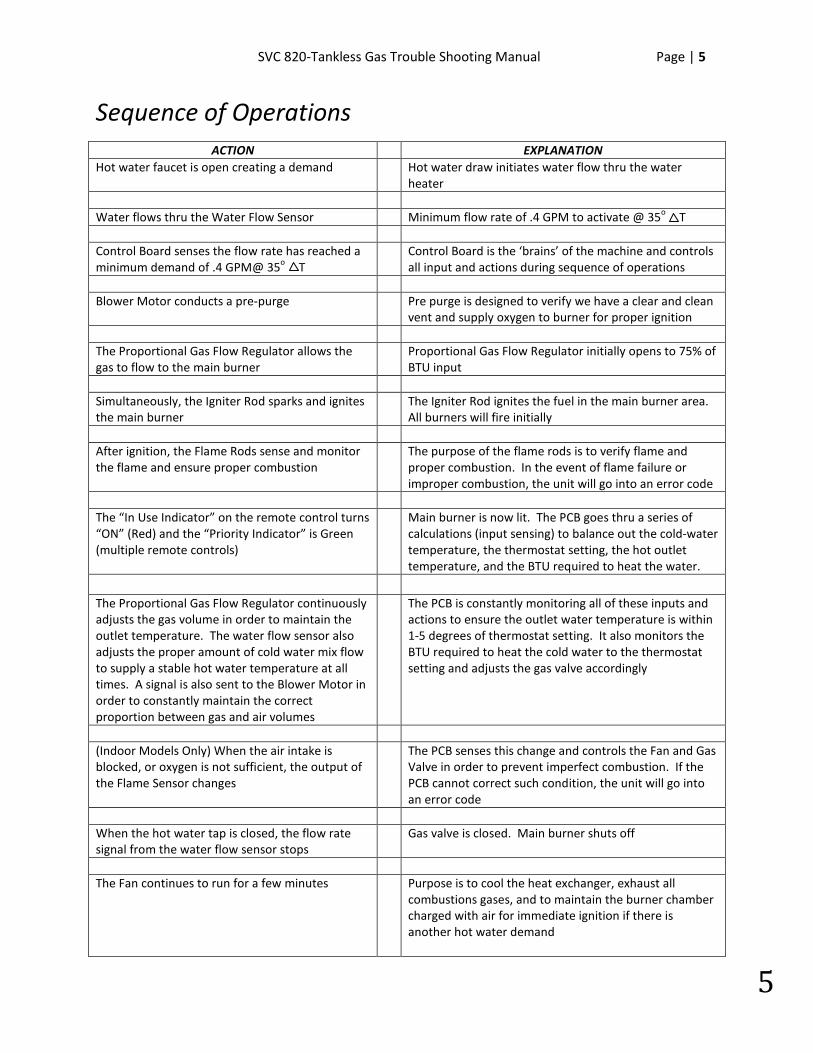
Sequence of Operations ACTION EXPLANATION
Hot water faucet is open creating a demand Hot water draw initiates water flow thru the water heater
Water flows thru the Water Flow Sensor Minimum flow rate of .4 GPM to activate @ 35o T Control Board senses the flow rate has reached a minimum demand of .4 GPM@ 35o T
Control Board is the ‘brains’ of the machine and controls all input and actions during sequence of operations
Blower Motor conducts a pre-purge Pre purge is designed to verify we have a clear and clean
vent and supply oxygen to burner for proper ignition The Proportional Gas Flow Regulator allows the gas to flow to the main burner
Proportional Gas Flow Regulator initially opens to 75% of BTU input
Simultaneously, the Igniter Rod sparks and ignites the main burner
The Igniter Rod ignites the fuel in the main burner area. All burners will fire initially
After ignition, the Flame Rods sense and monitor the flame and ensure proper combustion
The purpose of the flame rods is to verify flame and proper combustion. In the event of flame failure or improper combustion, the unit will go into an error code
The “In Use Indicator” on the remote control turns “ON” (Red) and the “Priority Indicator” is Green (multiple remote controls)
Main burner is now lit. The PCB goes thru a series of calculations (input sensing) to balance out the cold-water temperature, the thermostat setting, the hot outlet temperature, and the BTU required to heat the water.
The Proportional Gas Flow Regulator continuously adjusts the gas volume in order to maintain the outlet temperature. The water flow sensor also adjusts the proper amount of cold water mix flow to supply a stable hot water temperature at all times. A signal is also sent to the Blower Motor in order to constantly maintain the correct proportion between gas and air volumes
The PCB is constantly monitoring all of these inputs and actions to ensure the outlet water temperature is within 1-5 degrees of thermostat setting. It also monitors the BTU required to heat the cold water to the thermostat setting and adjusts the gas valve accordingly
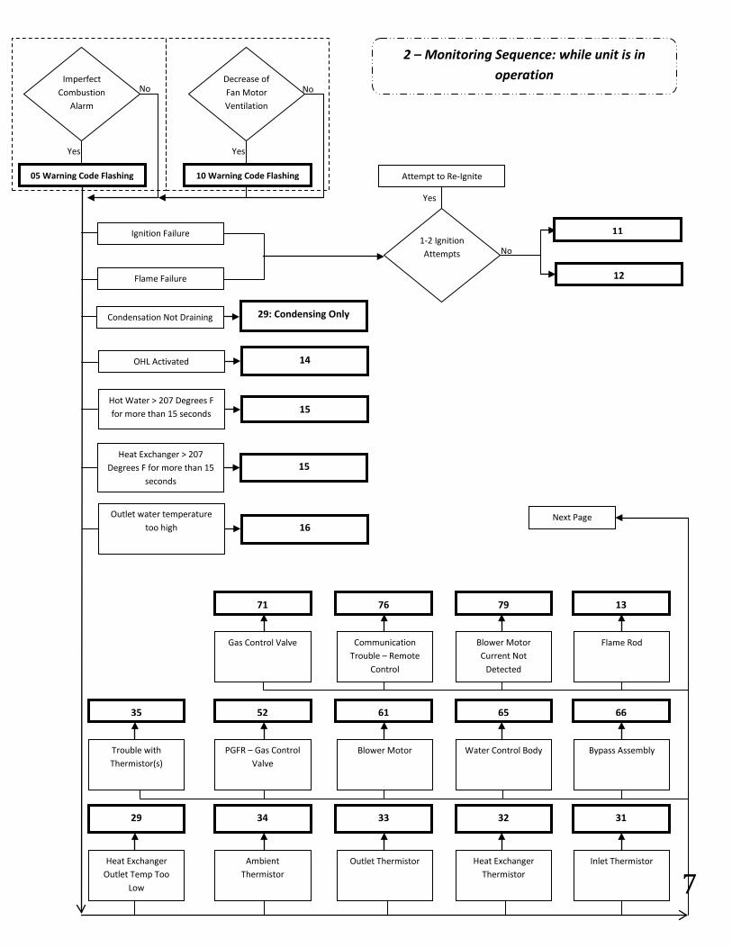
(Indoor Models Only) When the air intake is blocked, or oxygen is not sufficient, the output of the Flame Sensor changes
The PCB senses this change and controls the Fan and Gas Valve in order to prevent imperfect combustion. If the PCB cannot correct such condition, the unit will go into an error code
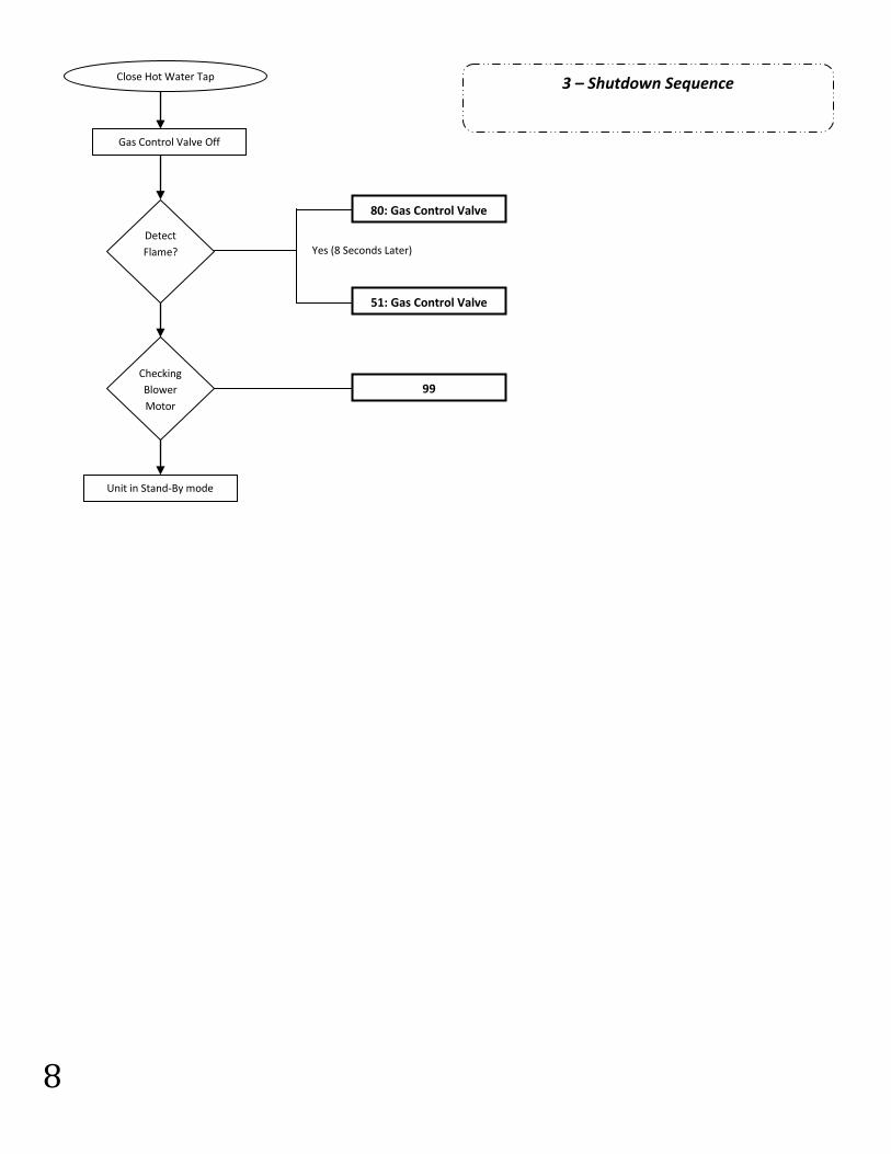
When the hot water tap is closed, the flow rate signal from the water flow sensor stops
Gas valve is closed. Main burner shuts off
The Fan continues to run for a few minutes Purpose is to cool the heat exchanger, exhaust all
combustions gases, and to maintain the burner chamber charged with air for immediate ignition if there is another hot water demand
6 | Page SVC 820 Tankless Gas Trouble Shooting Manual
6
YES
NO
Health Check
82 – Program Chip
79 – Blower Motor
71 – Gas Control Valve
76 – Remote Control
14 – OHL
Open Hot Water Tap
Up & Down
Buttons
24: Activated > 20 Seconds
Thermistors Check
Blower Speed
Flue Blockage
Detect Flame
False Flame
1-2 Ignition Attempt
31 – Inlet Thermistor
33 – Outlet Thermistor
32 – HE Thermistor
34 – Ambient Thermistor
61
90: > 12 seconds
72: > 5 seconds
11: > 2 Ignition Attempts
Igniter Rod Off
Gas Control Valve & Igniter Rod On
Blower On
Next Page
1 – Ignition Sequence
SEQUENCE OF OPERATIONS:
1. Ignition Sequence
2. Monitoring Sequence
3. Shutdown Sequence
Plug In
SVC 820-Tankless Gas Trouble Shooting Manual Page | 7
7
Flow Chart
No
Flame Failure
Ignition Failure
10 Warning Code Flashing 05 Warning Code Flashing
Yes Yes
No No Decrease of Fan Motor Ventilation
Imperfect Combustion
Alarm
Attempt to Re-Ignite
11
12
Yes
1-2 Ignition Attempts
Condensation Not Draining 29: Condensing Only
OHL Activated 14
Outlet water temperature too high 16
Hot Water > 207 Degrees F for more than 15 seconds 15
Heat Exchanger > 207 Degrees F for more than 15
seconds
15
Heat Exchanger Outlet Temp Too
Low
Ambient Thermistor
Outlet Thermistor Heat Exchanger Thermistor
Inlet Thermistor
29 34 33 32 31
Trouble with Thermistor(s)
PGFR – Gas Control Valve
Blower Motor Water Control Body Bypass Assembly
35 52 61 65 66
Gas Control Valve Communication Trouble – Remote
Control
Blower Motor Current Not
Detected
Flame Rod
71 76 79 13
Next Page
2 – Monitoring Sequence: while unit is in operation
8 | Page SVC 820 Tankless Gas Trouble Shooting Manual
8
Close Hot Water Tap
Checking Blower Motor
Detect Flame?
Gas Control Valve Off
Unit in Stand-By mode
80: Gas Control Valve
51: Gas Control Valve
Yes (8 Seconds Later)
99
3 – Shutdown Sequence
SVC 820-Tankless Gas Trouble Shooting Manual Page | 9
9
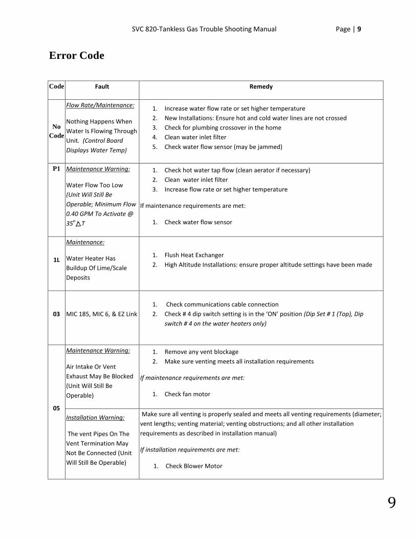
Error Code
Code Fault Remedy
No Code
Flow Rate/Maintenance:
Nothing Happens When Water Is Flowing Through Unit. (Control Board Displays Water Temp)
1. Increase water flow rate or set higher temperature 2. New Installations: Ensure hot and cold water lines are not crossed 3. Check for plumbing crossover in the home 4. Clean water inlet filter 5. Check water flow sensor (may be jammed)
P1 Maintenance Warning:
Water Flow Too Low (Unit Will Still Be Operable; Minimum Flow 0.40 GPM To Activate @ 35o ) T
1. Check hot water tap flow (clean aerator if necessary) 2. Clean water inlet filter 3. Increase flow rate or set higher temperature
If maintenance requirements are met:
1. Check water flow sensor
1L
Maintenance:
Water Heater Has Buildup Of Lime/Scale Deposits
1. Flush Heat Exchanger 2. High Altitude Installations: ensure proper altitude settings have been made
03 MIC 185, MIC 6, & EZ Link 1. Check communications cable connection 2. Check # 4 dip switch setting is in the ‘ON’ position (Dip Set # 1 (Top), Dip
switch # 4 on the water heaters only)
05
Maintenance Warning:
Air Intake Or Vent Exhaust May Be Blocked (Unit Will Still Be Operable)
1. Remove any vent blockage 2. Make sure venting meets all installation requirements
If maintenance requirements are met:
1. Check fan motor
Installation Warning:
The vent Pipes On The Vent Termination May Not Be Connected (Unit Will Still Be Operable)
Make sure all venting is properly sealed and meets all venting requirements (diameter; vent lengths; venting material; venting obstructions; and all other installation requirements as described in installation manual)
If installation requirements are met:
1. Check Blower Motor
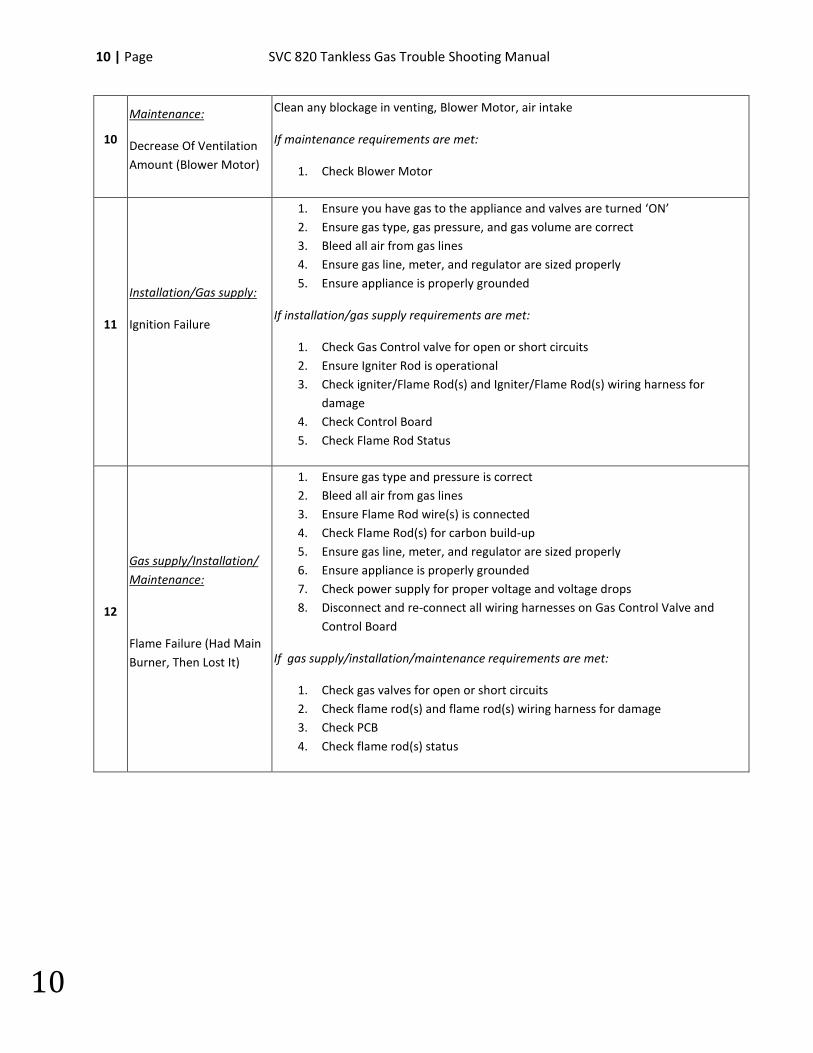
10 | Page SVC 820 Tankless Gas Trouble Shooting Manual
10
10
Maintenance:
Decrease Of Ventilation Amount (Blower Motor)
Clean any blockage in venting, Blower Motor, air intake
If maintenance requirements are met:
1. Check Blower Motor
11
Installation/Gas supply:
Ignition Failure
1. Ensure you have gas to the appliance and valves are turned ‘ON’ 2. Ensure gas type, gas pressure, and gas volume are correct 3. Bleed all air from gas lines 4. Ensure gas line, meter, and regulator are sized properly 5. Ensure appliance is properly grounded
If installation/gas supply requirements are met:
1. Check Gas Control valve for open or short circuits 2. Ensure Igniter Rod is operational 3. Check igniter/Flame Rod(s) and Igniter/Flame Rod(s) wiring harness for
damage 4. Check Control Board 5. Check Flame Rod Status
12
Gas supply/Installation/ Maintenance:
Flame Failure (Had Main Burner, Then Lost It)
1. Ensure gas type and pressure is correct 2. Bleed all air from gas lines 3. Ensure Flame Rod wire(s) is connected 4. Check Flame Rod(s) for carbon build-up 5. Ensure gas line, meter, and regulator are sized properly 6. Ensure appliance is properly grounded 7. Check power supply for proper voltage and voltage drops 8. Disconnect and re-connect all wiring harnesses on Gas Control Valve and
Control Board
If gas supply/installation/maintenance requirements are met:
1. Check gas valves for open or short circuits 2. Check flame rod(s) and flame rod(s) wiring harness for damage 3. Check PCB 4. Check flame rod(s) status
SVC 820-Tankless Gas Trouble Shooting Manual Page | 11
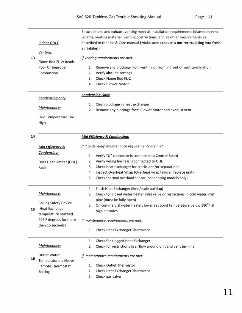
11
13
Indoor ONLY
Venting:
Flame Rod FL-2: Reads Poor Or Improper Combustion
Ensure intake and exhaust venting meet all installation requirements (diameter; vent lengths; venting material; venting obstructions; and all other requirements as described in the Use & Care manual {Make sure exhaust is not recirculating into fresh air intake})
If venting requirements are met:
1. Remove any blockage from venting or from in front of vent termination 2. Verify altitude settings 3. Check Flame Rod FL-2 4. Check Blower Motor
14
Condensing only:
Maintenance:
Flue Temperature Too High
Condensing Only:
1. Clean blockage in heat exchanger 2. Remove any blockage from Blower Motor and exhaust vent
Mid Efficiency & Condensing:
Over Heat Limiter (OHL) Fault
Mid Efficiency & Condensing:
If ‘Condensing’ maintenance requirements are met:
1. Verify “U” connector is connected to Control Board 2. Verify wiring harness is connected to OHL 3. Check heat exchanger for cracks and/or separations 4. Inspect Overheat Wrap (Overheat wrap failure: Replace unit) 5. Check thermal overload sensor (condensing models only)
15
Maintenance:
Boiling Safety Device (Heat Exchanger temperature reached 207 F degrees for more than 15 seconds)
1. Flush Heat Exchanger (lime/scale buildup) 2. Check for closed water heater inlet valve or restrictions in cold water inlet
pipe (must be fully open) 3. On commercial water heater, lower set point temperature below 1800F at
high altitudes
If maintenance requirements are met:
1. Check Heat Exchanger Thermistor
16
Maintenance:
Outlet Water Temperature Is Above Remote Thermostat Setting
1. Check for clogged Heat Exchanger 2. Check for restrictions in airflow around unit and vent terminal
If maintenance requirements are met:
1. Check Outlet Thermistor 2. Check Heat Exchanger Thermistor 3. Check gas valve
12 | Page SVC 820 Tankless Gas Trouble Shooting Manual
12
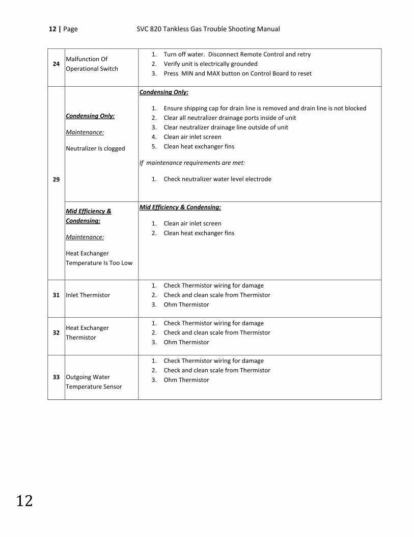
24 Malfunction Of Operational Switch
1. Turn off water. Disconnect Remote Control and retry 2. Verify unit is electrically grounded 3. Press MIN and MAX button on Control Board to reset
29
Condensing Only:
Maintenance:
Neutralizer Is clogged
Condensing Only:
1. Ensure shipping cap for drain line is removed and drain line is not blocked 2. Clear all neutralizer drainage ports inside of unit 3. Clear neutralizer drainage line outside of unit 4. Clean air inlet screen 5. Clean heat exchanger fins
If maintenance requirements are met:
1. Check neutralizer water level electrode
Mid Efficiency & Condensing:
Maintenance:
Heat Exchanger Temperature Is Too Low
Mid Efficiency & Condensing:
1. Clean air inlet screen 2. Clean heat exchanger fins
31 Inlet Thermistor 1. Check Thermistor wiring for damage 2. Check and clean scale from Thermistor 3. Ohm Thermistor
32 Heat Exchanger Thermistor
1. Check Thermistor wiring for damage 2. Check and clean scale from Thermistor 3. Ohm Thermistor
33
Outgoing Water Temperature Sensor
1. Check Thermistor wiring for damage 2. Check and clean scale from Thermistor 3. Ohm Thermistor
SVC 820-Tankless Gas Trouble Shooting Manual Page | 13
13
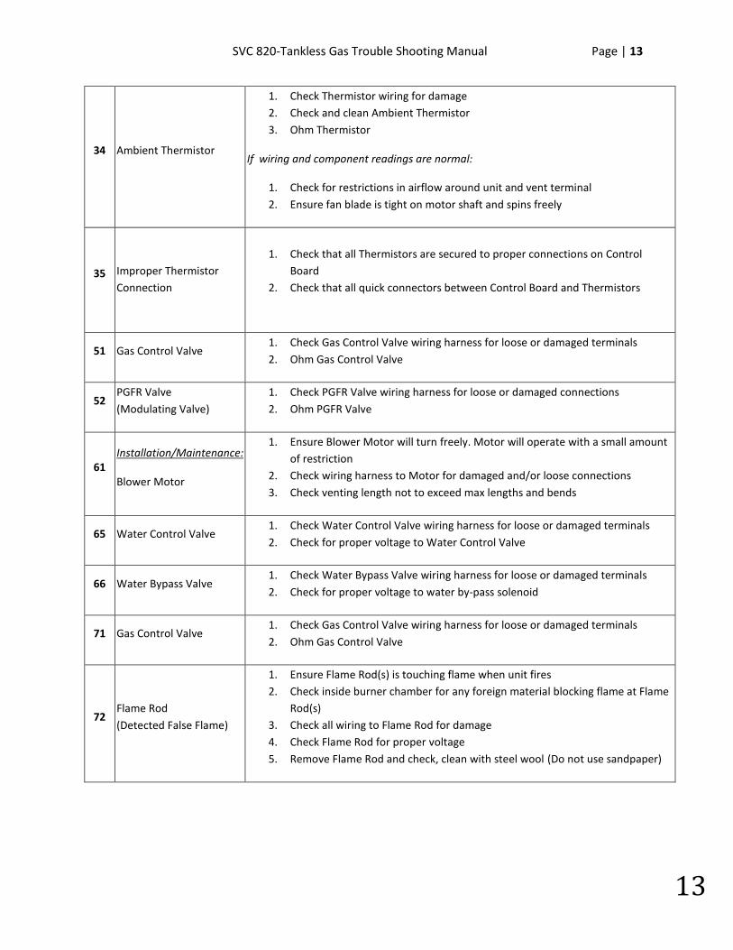
34 Ambient Thermistor
1. Check Thermistor wiring for damage 2. Check and clean Ambient Thermistor 3. Ohm Thermistor
If wiring and component readings are normal:
1. Check for restrictions in airflow around unit and vent terminal 2. Ensure fan blade is tight on motor shaft and spins freely
35 Improper Thermistor Connection
1. Check that all Thermistors are secured to proper connections on Control
Board 2. Check that all quick connectors between Control Board and Thermistors
51 Gas Control Valve 1. Check Gas Control Valve wiring harness for loose or damaged terminals 2. Ohm Gas Control Valve
52 PGFR Valve (Modulating Valve)
1. Check PGFR Valve wiring harness for loose or damaged connections 2. Ohm PGFR Valve
61 Installation/Maintenance:
Blower Motor
1. Ensure Blower Motor will turn freely. Motor will operate with a small amount of restriction
2. Check wiring harness to Motor for damaged and/or loose connections 3. Check venting length not to exceed max lengths and bends
65 Water Control Valve 1. Check Water Control Valve wiring harness for loose or damaged terminals 2. Check for proper voltage to Water Control Valve
66 Water Bypass Valve 1. Check Water Bypass Valve wiring harness for loose or damaged terminals 2. Check for proper voltage to water by-pass solenoid
71 Gas Control Valve 1. Check Gas Control Valve wiring harness for loose or damaged terminals 2. Ohm Gas Control Valve
72 Flame Rod (Detected False Flame)
1. Ensure Flame Rod(s) is touching flame when unit fires 2. Check inside burner chamber for any foreign material blocking flame at Flame
Rod(s) 3. Check all wiring to Flame Rod for damage 4. Check Flame Rod for proper voltage 5. Remove Flame Rod and check, clean with steel wool (Do not use sandpaper)
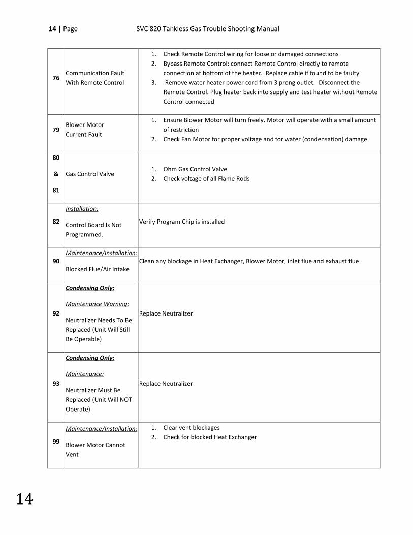
14 | Page SVC 820 Tankless Gas Trouble Shooting Manual
14
76 Communication Fault With Remote Control
1. Check Remote Control wiring for loose or damaged connections 2. Bypass Remote Control: connect Remote Control directly to remote
connection at bottom of the heater. Replace cable if found to be faulty 3. Remove water heater power cord from 3 prong outlet. Disconnect the
Remote Control. Plug heater back into supply and test heater without Remote Control connected
79 Blower Motor Current Fault
1. Ensure Blower Motor will turn freely. Motor will operate with a small amount of restriction
2. Check Fan Motor for proper voltage and for water (condensation) damage
80
&
81
Gas Control Valve 1. Ohm Gas Control Valve 2. Check voltage of all Flame Rods
82
Installation:
Control Board Is Not Programmed.
Verify Program Chip is installed
90 Maintenance/Installation:
Blocked Flue/Air Intake Clean any blockage in Heat Exchanger, Blower Motor, inlet flue and exhaust flue
92
Condensing Only:
Maintenance Warning:
Neutralizer Needs To Be Replaced (Unit Will Still Be Operable)
Replace Neutralizer
93
Condensing Only:
Maintenance:
Neutralizer Must Be Replaced (Unit Will NOT Operate)
Replace Neutralizer
99
Maintenance/Installation:
Blower Motor Cannot Vent
1. Clear vent blockages 2. Check for blocked Heat Exchanger
SVC 820-Tankless Gas Trouble Shooting Manual Page | 15
15
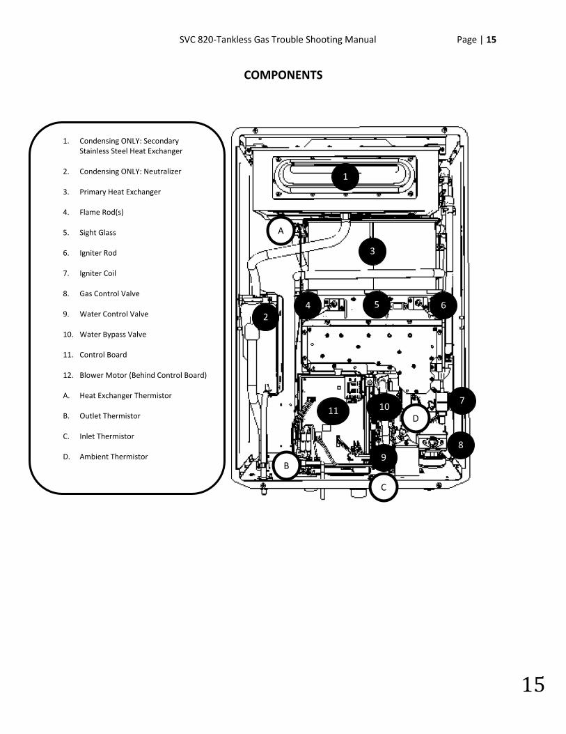
COMPONENTS
B
3
2 4 5
9
10 7
6
11
8
1
D
A
1. Condensing ONLY: Secondary Stainless Steel Heat Exchanger
2. Condensing ONLY: Neutralizer
3. Primary Heat Exchanger
4. Flame Rod(s)
5. Sight Glass
6. Igniter Rod
7. Igniter Coil
8. Gas Control Valve
9. Water Control Valve
10. Water Bypass Valve
11. Control Board
12. Blower Motor (Behind Control Board)
A. Heat Exchanger Thermistor
B. Outlet Thermistor
C. Inlet Thermistor
D. Ambient Thermistor
C
16 | Page SVC 820 Tankless Gas Trouble Shooting Manual
16
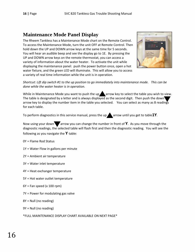
Maintenance Mode Panel Display The Rheem Tankless has a Maintenance Mode chart on the Remote Control. To access the Maintenance Mode, turn the unit OFF at Remote Control. Then hold down the UP and DOWN arrow keys at the same time for 5 seconds. You will hear an audible beep and see the display go to 1E. By pressing the UP and DOWN arrow keys on the remote thermostat, you can access a variety of information about the water heater. To activate the unit while displaying the maintenance panel: push the power button once, open a hot water fixture, and the green LED will illuminate. This will allow you to access a variety of real time information while the unit is in operation.
Shortcut: Lift dip switch #1 to the up position to go immediately into maintenance mode. This can be done while the water heater is in operation.
While in Maintenance Mode you want to push the up arrow key to select the table you wish to view. The table is designated by a letter and is always displayed as the second digit. Then push the down arrow key to display the number item in the table you selected. You can select as many as 8 readings for each table.
To perform diagnostics in this service manual, press the up arrow until you get to table1Y.
Now using your down arrow you can change the number in front of Y. As you move through the diagnostic readings, the selected table will flash first and then the diagnostic reading. You will see the
following as you navigate the Y table:
0Y = Flame Rod Status
1Y = Water Flow in gallons per minute
2Y = Ambient air temperature
3Y = Water inlet temperature
4Y = Heat exchanger temperature
5Y = Hot water outlet temperature
6Y = Fan speed (x 100 rpm)
7Y = Power for modulating gas valve
8Y = Null (no reading)
9Y = Null (no reading)
*FULL MAINTENANCE DISPLAY CHART AVAILABLE ON NEXT PAGE*
SVC 820-Tankless Gas Trouble Shooting Manual Page | 17
17
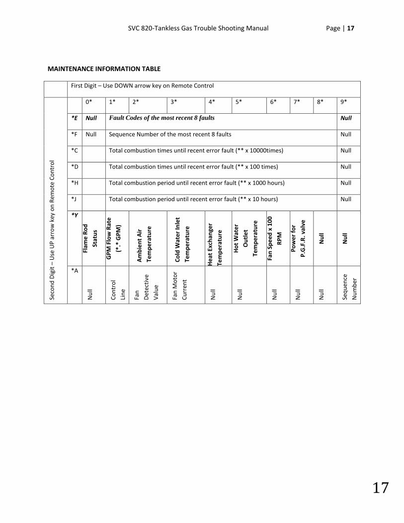
MAINTENANCE INFORMATION TABLE
First Digit – Use DOWN arrow key on Remote Control
Seco
nd D
igit
– U
se U
P ar
row
key
on
Rem
ote
Cont
rol
0* 1* 2* 3* 4* 5* 6* 7* 8* 9*
*E Null Fault Codes of the most recent 8 faults Null
*F Null Sequence Number of the most recent 8 faults Null
*C Total combustion times until recent error fault (** x 10000times) Null
*D Total combustion times until recent error fault (** x 100 times) Null
*H Total combustion period until recent error fault (** x 1000 hours) Null
*J Total combustion period until recent error fault (** x 10 hours) Null
*Y
Flam
e Ro
d
Stat
us
GPM
Flo
w R
ate
(*.*
GPM
)
Am
bien
t A
ir
Tem
pera
ture
Cold
Wat
er In
let
Tem
pera
ture
Hea
t Ex
chan
ger
Tem
pera
ture
Hot
Wat
er
Out
let
Tem
pera
ture
Fan
Spee
d x
100
RPM
Pow
er fo
r
P.G
.F.R
. val
ve
Nul
l
Nul
l
*A
Nul
l
Cont
rol
Line
Fa
n
Det
ectiv
e
Valu
e
Fan
Mot
or
Curr
ent
Nul
l
Nul
l
Nul
l
Nul
l
Nul
l
Sequ
ence
Num
ber

18 | Page SVC 820 Tankless Gas Trouble Shooting Manual
18
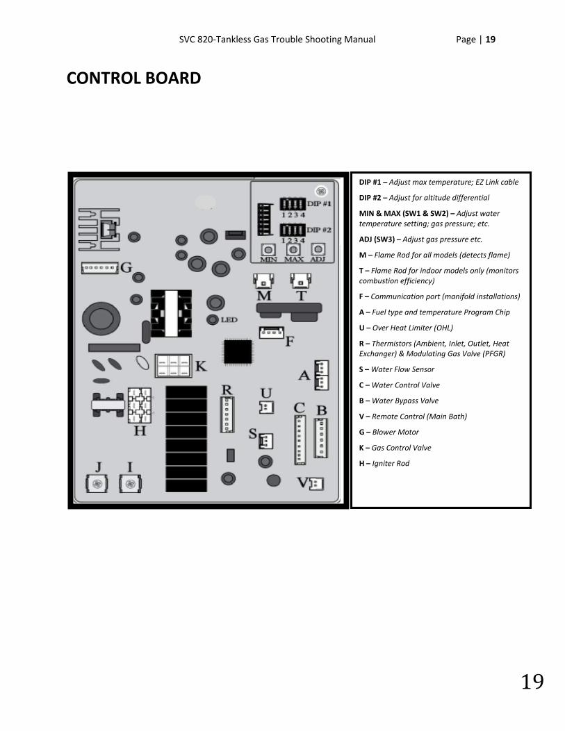
CONTROL BOARD – Color Picture • Each letter indicates the connector identifier
es ood. Proceed to your error code to resolve the sue. The error codes are listed in the table of ontents.
M T
MIN MAX ADJ
SVC 820-Tankless Gas Trouble Shooting Manual Page | 19
19
CONTROL BOARD
DIP #1 – Adjust max temperature; EZ Link cable
DIP #2 – Adjust for altitude differential
MIN & MAX (SW1 & SW2) – Adjust water temperature setting; gas pressure; etc.
ADJ (SW3) – Adjust gas pressure etc.
M – Flame Rod for all models (detects flame)
T – Flame Rod for indoor models only (monitors combustion efficiency)
F – Communication port (manifold installations)
A – Fuel type and temperature Program Chip
U – Over Heat Limiter (OHL)
R – Thermistors (Ambient, Inlet, Outlet, Heat Exchanger) & Modulating Gas Valve (PFGR)
S – Water Flow Sensor
C – Water Control Valve
B – Water Bypass Valve
V – Remote Control (Main Bath)
G – Blower Motor
K – Gas Control Valve
H – Igniter Rod

20 | Page SVC 820 Tankless Gas Trouble Shooting Manual
20
NOTES:
________________________________________________________________________________________________________________________________________________________________________________________________________________________________________________________________________________________________________________________________________________________________________________________________________________________________________________________________________________________________________________________________________________________________________________________________________________________________________________________________________________________________________________________________________________________________________________________________________________________________________________________________________________________________________________________________________________________
SVC 820-Tankless Gas Trouble Shooting Manual Page | 21
21
RESET PROCEDURE:
1. Turn unit OFF. Remove Front Cover. Locate the Dip Switches on the Control Board.
2. Make sure all the Dip Switches are OFF (down position). 3. Locate the #2 Dip Switch and turn it ON (up position) then
immediately turn it off. 4. Within 5 seconds, press and hold the MIN and MAX button for at
least 2 seconds. 5. The Remote Control will flash briefly. 6. You can operate unit.
CLEARING FAULT HISTORY PROCEDURE:
1. Turn unit OFF. Remove Front Cover. Locate the Dip Switches on the Control Board.
2. Make sure all the Dip Switches are OFF (down position). 3. Locate the #1 Dip Switch and turn it ON (up position) then
immediately turn it off. 4. Within 5 seconds, press and hold the MIN and MAX button for at
least 2 seconds. 5. The Remote Control will flash briefly. This indicated the fault
history has been cleared. 6. You can verify clearing history by entering Maintenance Mode
and check the code at location 1E. Should read NULL.
22 | Page SVC 820 Tankless Gas Trouble Shooting Manual
22
No Error Code & No Hot Water (Remote Control Displays Hot Water Temperature Setting)
Explanation: No hot water is delivered when water is flowing through unit and Remote Control displays the hot water temperature setting.
Possible Causes:
• Water Flow
• DIP 1 Setting On Main Control Board (PCB)
• Water flow sensor
Water Flow:
1. Turn OFF water supply to unit. Turn Remote Control OFF; unplug power cord at wall outlet. Wait 10 seconds; plug power cord back into outlet; wait 20 seconds; turn the Remote Control ON. Turn water supply ON; check the nearest hot water fixture for hot water. If you have hot water, then the unit needed to be reset.
2. Water flow might be too low. Open multiple hot water fixtures. If unit fires then there is not enough water flow to engage the unit at a particular fixture. Check your fixture aerator screen(s) for debris. Clean if necessary.
3. Your water lines might be crossed. Make sure your hot and cold water supply lines are connected to the appropriate hot and cold water assembly connections on the unit.
4. Your water flow may be restricted by a debris in Water Filter. Remove the water filter and inspect. Clean if necessary.
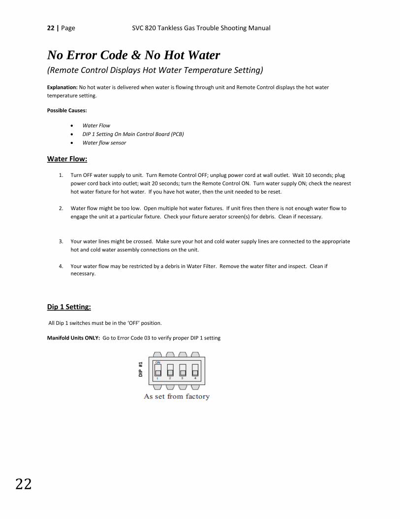
Dip 1 Setting:
All Dip 1 switches must be in the ‘OFF’ position.
Manifold Units ONLY: Go to Error Code 03 to verify proper DIP 1 setting
DIP
#1
SVC 820-Tankless Gas Trouble Shooting Manual Page | 23
23
P1 - Warning Code Explanation: No hot water is delivered when water is flowing through unit and Remote Control displays P1. When water flow does not reach a minimum 0.4 GPM rate @ 35o T, for five seconds, P1 warning code is displayed.
Possible Causes:
• Not Enough Water Flow
Water Flow:
Turn the water supply to the unit off. Turn the remote thermostat off, wait 10 seconds and turn the remote thermostat on. Turn the water supply to the unit on and check the nearest hot water fixture for hot water. If you have hot water, then the unit needed to be reset.
Your water lines might be crossed. Make sure your hot and cold water supply lines are connected to the appropriate hot and cold water connections on the unit.
Water flow might be too low. Open multiple hot water fixtures. If unit fires then there is not enough water flow to engage the unit at a particular fixture. Check your fixture aerator screen(s) for debris. Clean if necessary.
Your water flow may be restricted by a dirty In-Line Water Filter. Remove the water filter and inspect. Clean if necessary.
24 | Page SVC 820 Tankless Gas Trouble Shooting Manual
24
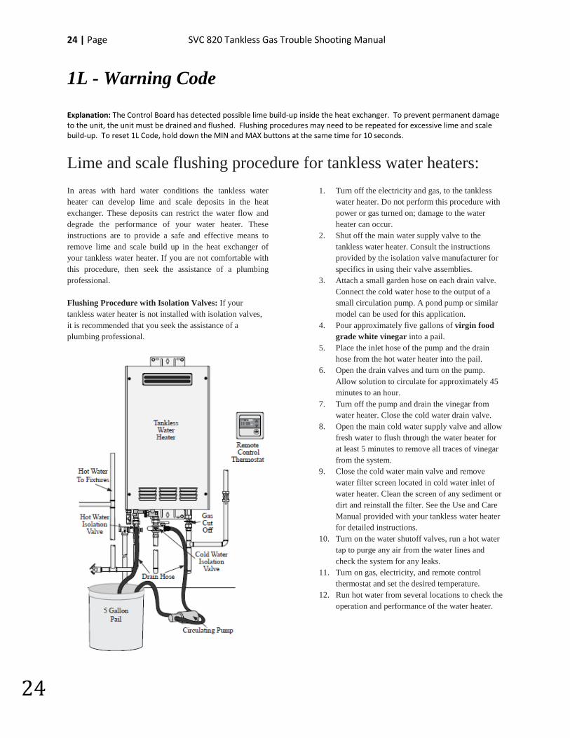
1L - Warning Code Explanation: The Control Board has detected possible lime build-up inside the heat exchanger. To prevent permanent damage to the unit, the unit must be drained and flushed. Flushing procedures may need to be repeated for excessive lime and scale build-up. To reset 1L Code, hold down the MIN and MAX buttons at the same time for 10 seconds.
Lime and scale flushing procedure for tankless water heaters: In areas with hard water conditions the tankless water heater can develop lime and scale deposits in the heat exchanger. These deposits can restrict the water flow and degrade the performance of your water heater. These instructions are to provide a safe and effective means to remove lime and scale build up in the heat exchanger of your tankless water heater. If you are not comfortable with this procedure, then seek the assistance of a plumbing professional. Flushing Procedure with Isolation Valves: If your tankless water heater is not installed with isolation valves, it is recommended that you seek the assistance of a plumbing professional.
1. Turn off the electricity and gas, to the tankless water heater. Do not perform this procedure with power or gas turned on; damage to the water heater can occur.
2. Shut off the main water supply valve to the tankless water heater. Consult the instructions provided by the isolation valve manufacturer for specifics in using their valve assemblies.
3. Attach a small garden hose on each drain valve. Connect the cold water hose to the output of a small circulation pump. A pond pump or similar model can be used for this application.
4. Pour approximately five gallons of virgin food grade white vinegar into a pail.
5. Place the inlet hose of the pump and the drain hose from the hot water heater into the pail.
6. Open the drain valves and turn on the pump. Allow solution to circulate for approximately 45 minutes to an hour.
7. Turn off the pump and drain the vinegar from water heater. Close the cold water drain valve.
8. Open the main cold water supply valve and allow fresh water to flush through the water heater for at least 5 minutes to remove all traces of vinegar from the system.
9. Close the cold water main valve and remove water filter screen located in cold water inlet of water heater. Clean the screen of any sediment or dirt and reinstall the filter. See the Use and Care Manual provided with your tankless water heater for detailed instructions.
10. Turn on the water shutoff valves, run a hot water tap to purge any air from the water lines and check the system for any leaks.
11. Turn on gas, electricity, and remote control thermostat and set the desired temperature.
12. Run hot water from several locations to check the operation and performance of the water heater.
SVC 820-Tankless Gas Trouble Shooting Manual Page | 25
25
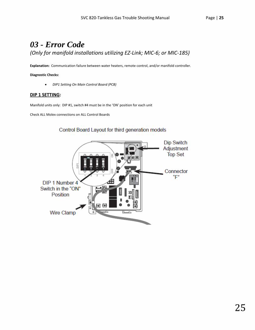
03 - Error Code (Only for manifold installations utilizing EZ-Link; MIC-6; or MIC-185) Explanation: Communication failure between water heaters, remote control, and/or manifold controller. Diagnostic Checks:
• DIP1 Setting On Main Control Board (PCB)
DIP 1 SETTING:
Manifold units only: DIP #1, switch #4 must be in the ‘ON’ position for each unit
Check ALL Molex connections on ALL Control Boards
26 | Page SVC 820 Tankless Gas Trouble Shooting Manual
26
05 – Warning Code Explanation: The Flame Rod has detected improper burner combustion. The unit is NOT able to maintain the proper fuel/air mixture for proper combustion. This warning code is commonly caused by VENTING and/or GAS SUPPLY. The unit will continue to operate and attempt to resolve improper combustion, but may eventually shut down with an error code 11, 12, or 13. Diagnostic Checks:
• GAS SUPPLY & VENTING • Dip #2 Setting On Printed Circuit Board (PCB)
GAS SUPPLY & VENTING **REFER TO USE & CARE MANUAL**
Make sure you have sufficient fuel for the unit to operate properly.
1. Gas Type (LP or Natural Gas) 2. Gas Pressure 3. Gas Pipe Size 4. Gas Flex Line Not To Exceed 36” In Length, Has The Proper ID (Inside Diameter), & Correct BTU Rating 5. Gas Regulator 6. Gas Shut Off Valves 7. Air In Gas Line
Visually inspect venting for possible blockage and/or recirculation of exhaust. 1. Approved Venting Materials 2. Approved Vent Terminations 3. Vent Lengths 4. Location Of Vent Termination (Recirculation of exhaust) 5. Blocked Venting 6. Venting Not Sealed Properly
SVC 820-Tankless Gas Trouble Shooting Manual Page | 27
27
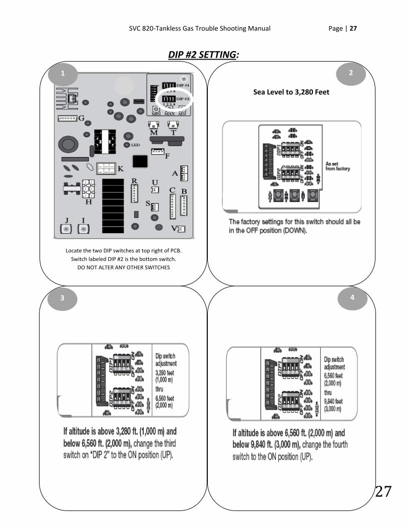
DIP #2 SETTING:
Locate the two DIP switches at top right of PCB. Switch labeled DIP #2 is the bottom switch.
DO NOT ALTER ANY OTHER SWITCHES
1
Sea Level to 3,280 Feet
3
2
4
28 | Page SVC 820 Tankless Gas Trouble Shooting Manual
28
NOTES:
________________________________________________________________________________________________________________________________________________________________________________________________________________________________________________________________________________________________________________________________________________________________________________________________________________________________________________________________________________________________________________________________________________________________________________________________________________________________________________________________________________________________________________________________________________________________________________________________________________________________________________________________________________________________________________________________________________________
SVC 820-Tankless Gas Trouble Shooting Manual Page | 29
29
10 – Warning Code Explanation: The Blower Motor is not creating enough ventilation. The system passed the pre-purge cycle, but detects vent blockage during normal operation. The unit will continue to operate but may eventually shut down with Error Code 99. First check your GAS SUPPLY & VENTING; the most common causes for Error Code 10. Diagnostic Checks:
• GAS SUPPLY & VENTING • Blower Motor
GAS SUPPLY & VENTING **REFER TO USE & CARE MANUAL**
Make sure you have sufficient fuel for the unit to operate properly.
1. Gas Type (LP or Natural Gas) 2. Gas Pressure 3. Gas Pipe Size 4. Gas Flex Line Not To Exceed 36” In Length, has the proper ID (Inside Diameter), and correct BTU rating 5. Gas Regulator 6. Gas Shut Off Valves 7. Air In Gas Line
Visually inspect venting for possible blockage and/or recirculation of exhaust.
1. Approved Venting Materials 2. Approved Vent Terminations 3. Vent Lengths 4. Location Of Vent Termination (Recirculation of exhaust) 5. Blocked Venting 6. Venting Not Sealed Properly

30 | Page SVC 820 Tankless Gas Trouble Shooting Manual
30
BLOWER MOTOR DIAGNOSTICS:
Turn power OFF. Remove and reinsert connector “G” on Control Board. Attempt to operate unit again. IF 10
Warning Code does NOT display, unit had a loose connection.
1
Remove 3 screws holding Blower Motor in place. Clean Blower Motor and reassemble unit. Attempt to operate
unit again. IF 10 Warning Code does NOT display: Blower Motor needed to be cleaned.
Turn power OFF. Remove 3 screws for Control Board mounting bracket. Remove connectors “M”, “T”, & “G”.
Pull PCB out of way to access Blower Motor.
Locate Min & Max buttons on Control Board. Continue to diagnostic chart on next page.
3
2
4
Bottom of Unit
Control Board
Screws
Blower Motor
SVC 820-Tankless Gas Trouble Shooting Manual Page | 31
31
BLOWER MOTOR Diagnostic Chart
YES NO
NO
YES
YES
NO
Test DC voltage across black and red wires on connector “G”:
144 – 192 DC VOLTS
Is the DC voltage OK?
Remove and reinsert connector “G” at Control Board.
Attempt to operate unit again. IF unit continues to display Error Code 10:
Replace Control Board
Is the DC voltage OK?
Press and hold down “MAX” button on Control Board to activate the Blower Motor. While Blower Motor is running, test DC voltage across black and white wires
on connector “G”:
12 – 18 DC VOLTS
Press and hold down “MAX” button on Control Board to activate the blower motor. While blower is
running, test DC voltage across black and blue wires on connector “G”:
4 – 10 DC VOLTS
Remove and reinsert connector “G” at Control Board.
Attempt to operate unit again. IF unit continues to display Error Code 10:
Replace Control Board
Is the DC voltage OK? Replace Blower Motor
Attempt to operate unit again. If unit continues to display Warning Code 10:
Control Board and Blower Motor are ‘OK’: CHECK VENTING & GAS SUPPLY

32 | Page SVC 820 Tankless Gas Trouble Shooting Manual
32
NOTES:
________________________________________________________________________________________________________________________________________________________________________________________________________________________________________________________________________________________________________________________________________________________________________________________________________________________________________________________________________________________________________________________________________________________________________________________________________________________________________________________________________________________________________________________________________________________________________________________________________________________________________________________________________________________________________________________________________________________
SVC 820-Tankless Gas Trouble Shooting Manual Page | 33
33
11 – Error Code Explanation: This error code is commonly a result of GAS SUPPLY and/or VENTING. Flame Rod(s) does not detect flame. This Is caused by the following: Inadequate GAS SUPPLY; Inadequate VENTING; Igniter Rod NOT sparking; Build-up on Flame Rod(s) caused by inadequate GAS SUPPLY and/or VENTING; Gas Valve. IMPORTANT: If all water heater components test ‘OK’, you must thoroughly inspect your GAS SUPPLY & VENTING. First Check: GAS SUPPLY & VENTING Diagnostic Checks:
• GAS SUPPLY & VENTING • Igniter Rod • Flame Rod(s) • Gas Control Valve
GAS SUPPLY & VENTING **REFER TO USE & CARE MANUAL**
Make sure you have sufficient fuel for the unit to operate properly.
1. Gas Type (LP or Natural Gas) 2. Gas Pressure 3. Gas Pipe Size 4. Gas Flex Line Not To Exceed 36” In Length, has the proper ID (Inside Diameter), and correct BTU rating 5. Gas Regulator 6. Gas Shut Off Valves 7. Air In Gas Line
Visually inspect venting for possible blockage and/or recirculation of exhaust. 1. Approved Venting Materials 2. Approved Vent Terminations 3. Vent Lengths 4. Location Of Vent Termination (Recirculation of exhaust) 5. Blocked Venting 6. Venting Not Sealed Properly
34 | Page SVC 820 Tankless Gas Trouble Shooting Manual
34
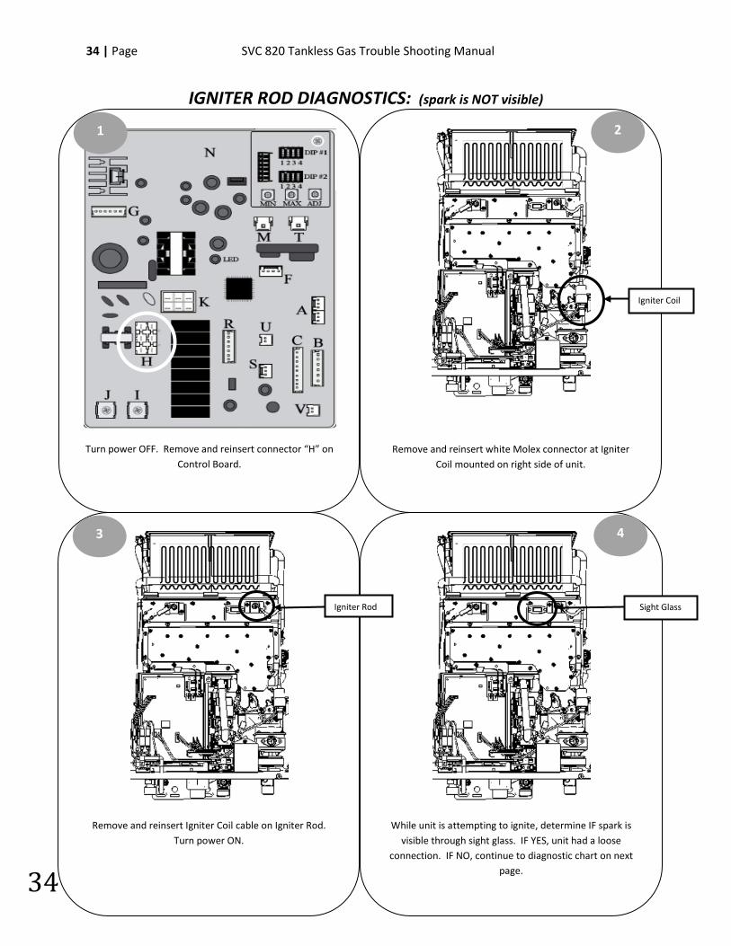
IGNITER ROD DIAGNOSTICS: (spark is NOT visible)
Turn power OFF. Remove and reinsert connector “H” on Control Board.
1
Remove and reinsert Igniter Coil cable on Igniter Rod. Turn power ON.
Remove and reinsert white Molex connector at Igniter Coil mounted on right side of unit.
While unit is attempting to ignite, determine IF spark is visible through sight glass. IF YES, unit had a loose
connection. IF NO, continue to diagnostic chart on next page.
3
2
4
Igniter Rod Sight Glass
Igniter Coil
SVC 820-Tankless Gas Trouble Shooting Manual Page | 35
35
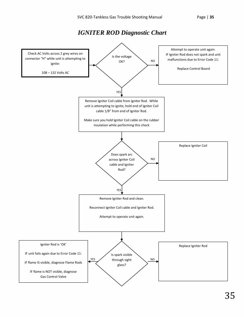
IGNITER ROD Diagnostic Chart
YES
NO
NO
Check AC Volts across 2 grey wires on connector “H” while unit is attempting to
ignite:
108 – 132 Volts AC
Attempt to operate unit again. IF Igniter Rod does not spark and unit
malfunctions due to Error Code 11:
Replace Control Board
Replace Igniter Coil
YES
YES
Is the voltage OK?
Does spark arc across Igniter Coil cable and Igniter
Rod?
Remove Igniter Coil cable from Igniter Rod. While unit is attempting to ignite, hold end of Igniter Coil
cable 1/8” from end of Igniter Rod.
Make sure you hold Igniter Coil cable on the rubber insulation while performing this check
Remove Igniter Rod and clean.
Reconnect Igniter Coil cable and Igniter Rod.
Attempt to operate unit again.
NO Is spark visible through sight
glass?
Replace Igniter Rod
Igniter Rod is ‘OK’
IF unit fails again due to Error Code 11:
IF flame IS visible, diagnose Flame Rods
IF flame is NOT visible, diagnose Gas Control Valve
36 | Page SVC 820 Tankless Gas Trouble Shooting Manual
36
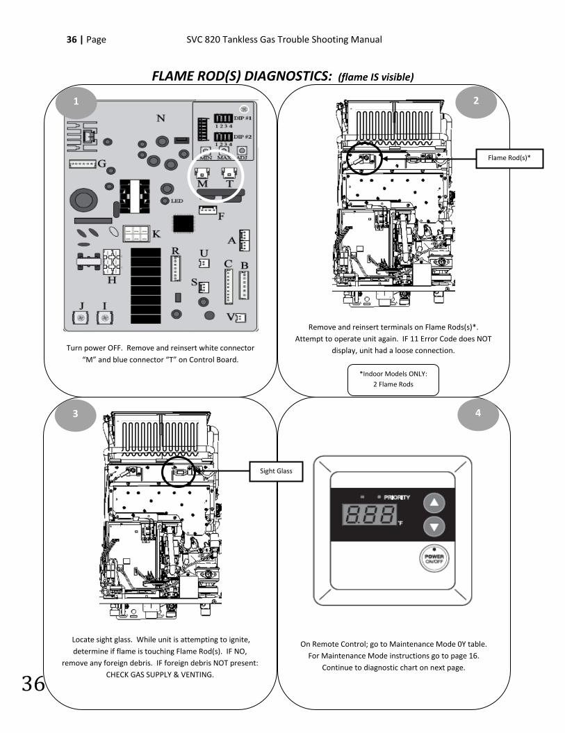
FLAME ROD(S) DIAGNOSTICS: (flame IS visible)
Turn power OFF. Remove and reinsert white connector “M” and blue connector “T” on Control Board.
1
Locate sight glass. While unit is attempting to ignite, determine if flame is touching Flame Rod(s). IF NO,
remove any foreign debris. IF foreign debris NOT present: CHECK GAS SUPPLY & VENTING.
Remove and reinsert terminals on Flame Rods(s)*. Attempt to operate unit again. IF 11 Error Code does NOT
display, unit had a loose connection.
On Remote Control; go to Maintenance Mode 0Y table. For Maintenance Mode instructions go to page 16.
Continue to diagnostic chart on next page.
3
2
4
*Indoor Models ONLY: 2 Flame Rods
Sight Glass
Flame Rod(s)*
SVC 820-Tankless Gas Trouble Shooting Manual Page | 37
37
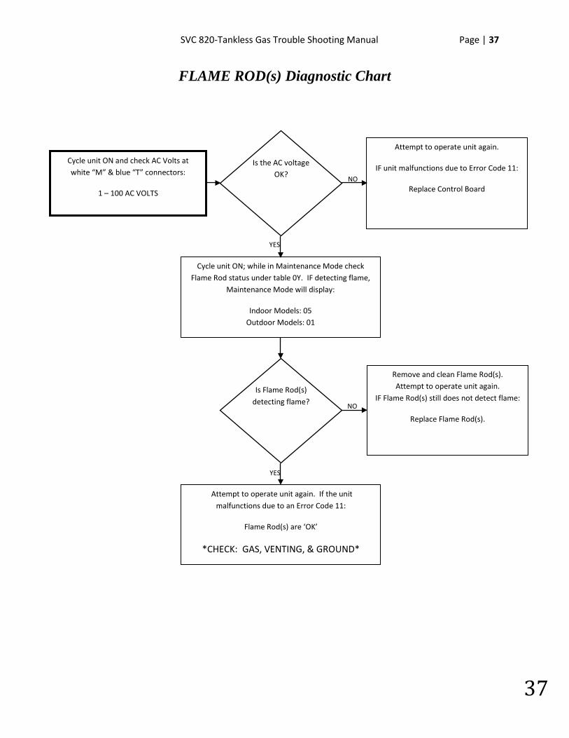
FLAME ROD(s) Diagnostic Chart
NO
YES
YES
NO
Cycle unit ON and check AC Volts at white “M” & blue “T” connectors:
1 – 100 AC VOLTS
Is the AC voltage OK?
Attempt to operate unit again.
IF unit malfunctions due to Error Code 11:
Replace Control Board
Is Flame Rod(s) detecting flame?
Cycle unit ON; while in Maintenance Mode check Flame Rod status under table 0Y. IF detecting flame,
Maintenance Mode will display:
Indoor Models: 05 Outdoor Models: 01
Attempt to operate unit again. If the unit malfunctions due to an Error Code 11:
Flame Rod(s) are ‘OK’
*CHECK: GAS, VENTING, & GROUND*
Remove and clean Flame Rod(s). Attempt to operate unit again.
IF Flame Rod(s) still does not detect flame:
Replace Flame Rod(s).
38 | Page SVC 820 Tankless Gas Trouble Shooting Manual
38
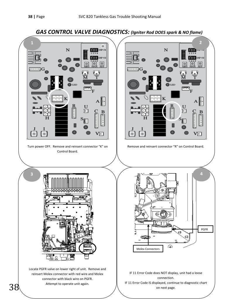
GAS CONTROL VALVE DIAGNOSTICS: (Igniter Rod DOES spark & NO flame)
Turn power OFF. Remove and reinsert connector “K” on Control Board.
1
Locate PGFR valve on lower right of unit. Remove and reinsert Molex connector with red wire and Molex
connector with black wire on PGFR. Attempt to operate unit again.
Remove and reinsert connector “R” on Control Board.
IF 11 Error Code does NOT display, unit had a loose connection.
IF 11 Error Code IS displayed, continue to diagnostic chart on next page.
3
2
4
PGFR
Molex Connectors
SVC 820-Tankless Gas Trouble Shooting Manual Page | 39
39
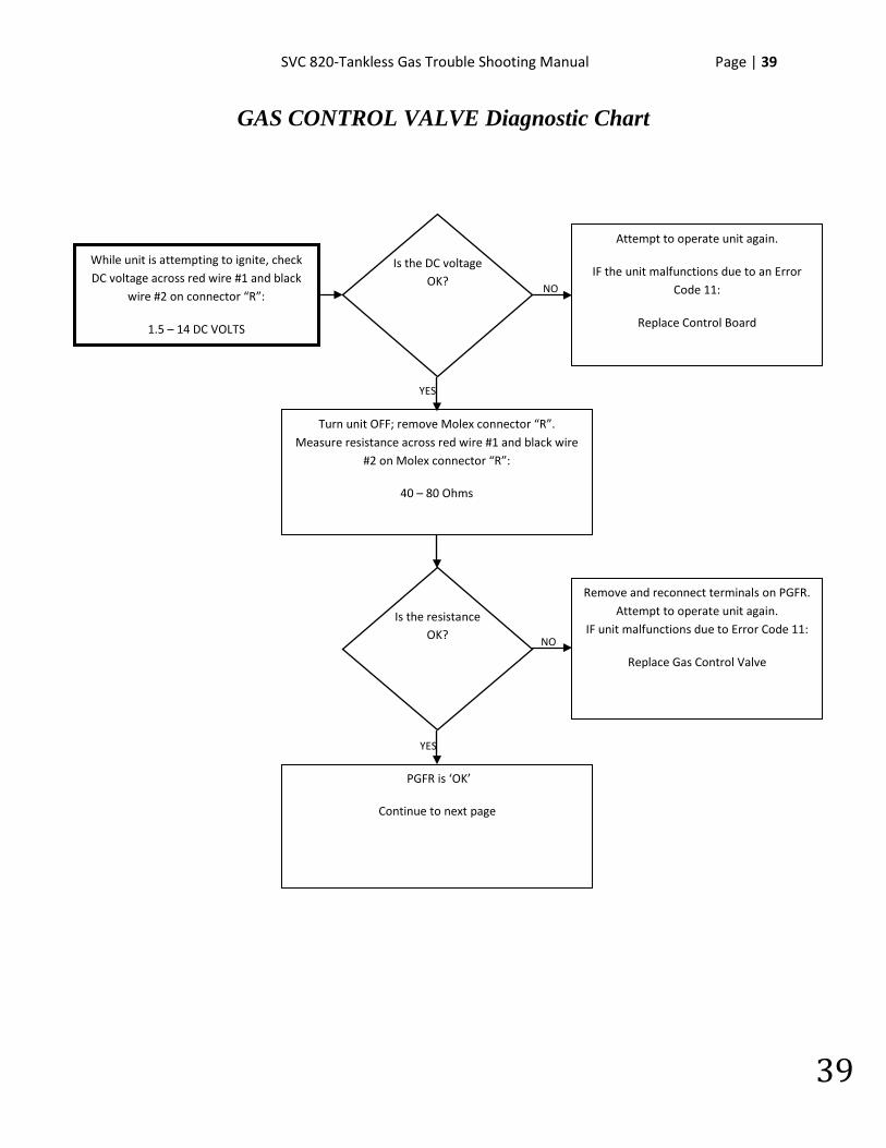
GAS CONTROL VALVE Diagnostic Chart
NO
YES
YES
NO
While unit is attempting to ignite, check DC voltage across red wire #1 and black
wire #2 on connector “R”:
1.5 – 14 DC VOLTS
Is the DC voltage OK?
Attempt to operate unit again.
IF the unit malfunctions due to an Error Code 11:
Replace Control Board
Is the resistance OK?
Turn unit OFF; remove Molex connector “R”. Measure resistance across red wire #1 and black wire
#2 on Molex connector “R”:
40 – 80 Ohms
PGFR is ‘OK’
Continue to next page
Remove and reconnect terminals on PGFR. Attempt to operate unit again.
IF unit malfunctions due to Error Code 11:
Replace Gas Control Valve
40 | Page SVC 820 Tankless Gas Trouble Shooting Manual
40
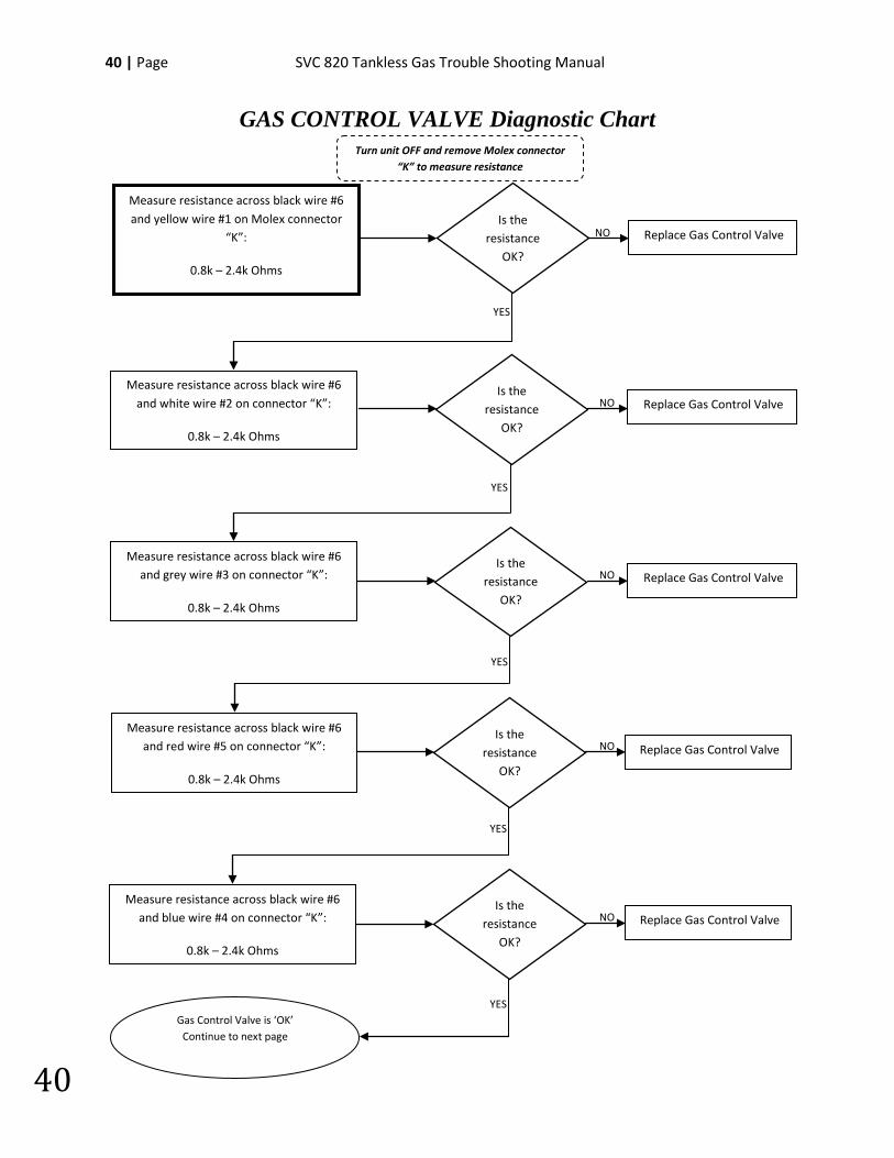
GAS CONTROL VALVE Diagnostic Chart
NO Is the
resistance OK?
YES
Measure resistance across black wire #6 and yellow wire #1 on Molex connector
“K”:
0.8k – 2.4k Ohms
Replace Gas Control Valve
Measure resistance across black wire #6 and red wire #5 on connector “K”:
0.8k – 2.4k Ohms
Measure resistance across black wire #6 and blue wire #4 on connector “K”:
0.8k – 2.4k Ohms
Measure resistance across black wire #6 and white wire #2 on connector “K”:
0.8k – 2.4k Ohms
Measure resistance across black wire #6 and grey wire #3 on connector “K”:
0.8k – 2.4k Ohms
Is the resistance
OK?
YES
YES
Is the resistance
OK?
YES
Is the resistance
OK?
YES
Is the resistance
OK?
NO
NO
NO
NO
Gas Control Valve is ‘OK’ Continue to next page
Turn unit OFF and remove Molex connector “K” to measure resistance
Replace Gas Control Valve
Replace Gas Control Valve
Replace Gas Control Valve
Replace Gas Control Valve
SVC 820-Tankless Gas Trouble Shooting Manual Page | 41
41
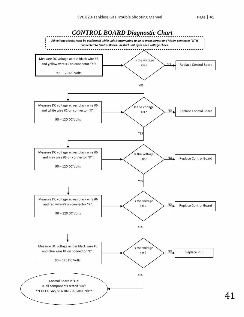
CONTROL BOARD Diagnostic Chart
NO
NO
NO
NO
NO
YES
Measure DC voltage across black wire #6 and yellow wire #1 on connector “K”:
90 – 120 DC Volts
Is the voltage OK?
Measure DC voltage across black wire #6 and red wire #5 on connector “K”:
90 – 120 DC Volts
Measure DC voltage across black wire #6 and blue wire #4 on connector “K”:
90 – 120 DC Volts
Measure DC voltage across black wire #6 and white wire #2 on connector “K”:
90 – 120 DC Volts
Measure DC voltage across black wire #6 and grey wire #3 on connector “K”:
90 – 120 DC Volts
Is the voltage OK?
YES
YES
Is the voltage OK?
YES
Is the voltage OK?
YES
Is the voltage OK?
Control Board is ‘OK’ IF all components tested ‘OK’:
**CHECK GAS, VENTING, & GROUND**
All voltage checks must be performed while unit is attempting to go to main burner and Molex connector “K” IS connected to Control Board. Restart unit after each voltage check.
Replace Control Board
Replace PCB
Replace Control Board
Replace Control Board
Replace Control Board

42 | Page SVC 820 Tankless Gas Trouble Shooting Manual
42
NOTES:
________________________________________________________________________________________________________________________________________________________________________________________________________________________________________________________________________________________________________________________________________________________________________________________________________________________________________________________________________________________________________________________________________________________________________________________________________________________________________________________________________________________________________________________________________________________________________________________________________________________________________________________________________________________________________________________________________________________
SVC 820-Tankless Gas Trouble Shooting Manual Page | 43
43
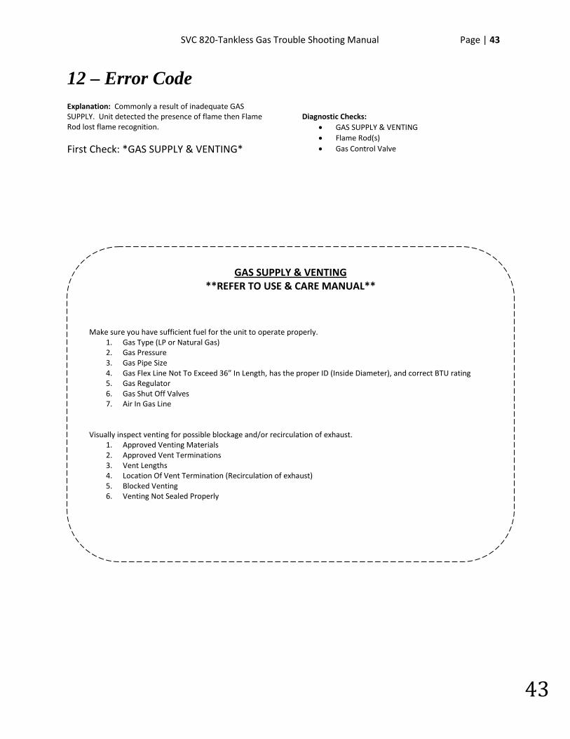
12 – Error Code Explanation: Commonly a result of inadequate GAS SUPPLY. Unit detected the presence of flame then Flame Rod lost flame recognition.
First Check: *GAS SUPPLY & VENTING*
Diagnostic Checks:
• GAS SUPPLY & VENTING • Flame Rod(s) • Gas Control Valve
GAS SUPPLY & VENTING **REFER TO USE & CARE MANUAL**
Make sure you have sufficient fuel for the unit to operate properly.
1. Gas Type (LP or Natural Gas) 2. Gas Pressure 3. Gas Pipe Size 4. Gas Flex Line Not To Exceed 36” In Length, has the proper ID (Inside Diameter), and correct BTU rating 5. Gas Regulator 6. Gas Shut Off Valves 7. Air In Gas Line
Visually inspect venting for possible blockage and/or recirculation of exhaust. 1. Approved Venting Materials 2. Approved Vent Terminations 3. Vent Lengths 4. Location Of Vent Termination (Recirculation of exhaust) 5. Blocked Venting 6. Venting Not Sealed Properly

44 | Page SVC 820 Tankless Gas Trouble Shooting Manual
44
FLAME ROD(S) DIAGNOSTICS: (flame IS visible)
Turn power OFF. Remove and reinsert white connector “M” and blue connector “T” on Control Board.
1
Locate sight glass. While unit is attempting to ignite, determine if flame is touching Flame Rod(s). IF NO,
remove any foreign debris. IF foreign debris NOT present: CHECK GAS SUPPLY & VENTING.
Remove and reinsert terminals on Flame Rod(s)*. Attempt to operate unit again. IF 11 Error Code does NOT
display, unit had a loose connection.
On Remote Control; go to Maintenance Mode 0Y table. For Maintenance Mode instructions go to page 16.
Continue to diagnostic chart on next page.
3
2
4
Flame Rod(s)*
*Indoor Models ONLY: 2 Flame Rods
Sight Glass
SVC 820-Tankless Gas Trouble Shooting Manual Page | 45
45
FLAME ROD(s) Diagnostic Chart
NO
YES
YES
NO
Cycle unit ON and check AC Volts at white “M” & blue “T” connectors:
1 – 100 AC VOLTS
Is the AC voltage OK?
Attempt to operate unit again.
IF the unit malfunctions due to an Error Code 12:
Replace Control Board
Is Flame Rod(s) detecting flame?
Cycle unit ON; while in Maintenance Mode check Flame Rod(s) status under table 0Y. IF detecting
flame, Maintenance Mode will display:
Indoor Models: 05 Outdoor Models: 01
Attempt to operate unit again. IF the unit malfunctions due to an Error Code 12:
Flame Rods(s) are ‘OK’
*CHECK: GAS, VENTING, & GROUND*
Remove and clean Flame Rod(s). Attempt to operate unit again.
IF Flame Rod(s) still does not detect flame:
Replace Flame Rod(s).

46 | Page SVC 820 Tankless Gas Trouble Shooting Manual
46
NOTES:
________________________________________________________________________________________________________________________________________________________________________________________________________________________________________________________________________________________________________________________________________________________________________________________________________________________________________________________________________________________________________________________________________________________________________________________________________________________________________________________________________________________________________________________________________________________________________________________________________________________________________________________________________________________________________________________________________________________
SVC 820-Tankless Gas Trouble Shooting Manual Page | 47
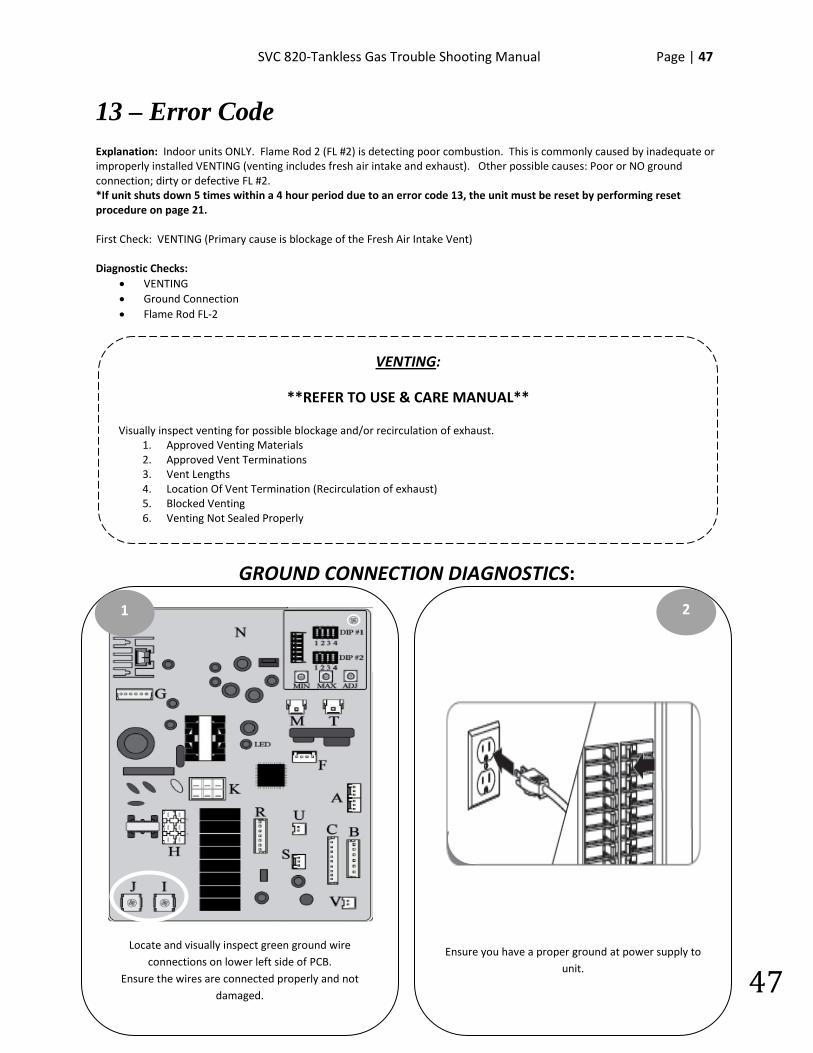
47
13 – Error Code Explanation: Indoor units ONLY. Flame Rod 2 (FL #2) is detecting poor combustion. This is commonly caused by inadequate or improperly installed VENTING (venting includes fresh air intake and exhaust). Other possible causes: Poor or NO ground connection; dirty or defective FL #2. *If unit shuts down 5 times within a 4 hour period due to an error code 13, the unit must be reset by performing reset procedure on page 21. First Check: VENTING (Primary cause is blockage of the Fresh Air Intake Vent) Diagnostic Checks:
• VENTING • Ground Connection • Flame Rod FL-2
GROUND CONNECTION DIAGNOSTICS:
VENTING:
**REFER TO USE & CARE MANUAL**
Visually inspect venting for possible blockage and/or recirculation of exhaust. 1. Approved Venting Materials 2. Approved Vent Terminations 3. Vent Lengths 4. Location Of Vent Termination (Recirculation of exhaust) 5. Blocked Venting 6. Venting Not Sealed Properly
Locate and visually inspect green ground wire connections on lower left side of PCB.
Ensure the wires are connected properly and not damaged.
1
Ensure you have a proper ground at power supply to unit.
2
48 | Page SVC 820 Tankless Gas Trouble Shooting Manual
48
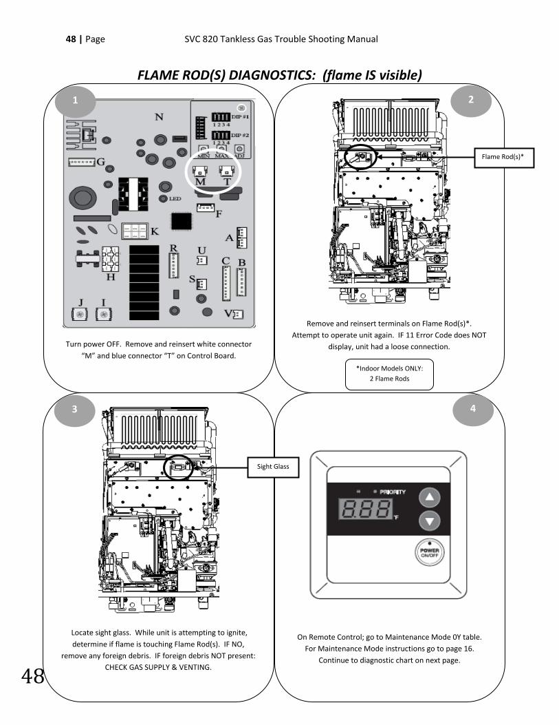
FLAME ROD(S) DIAGNOSTICS: (flame IS visible)
Turn power OFF. Remove and reinsert white connector “M” and blue connector “T” on Control Board.
1
Locate sight glass. While unit is attempting to ignite, determine if flame is touching Flame Rod(s). IF NO,
remove any foreign debris. IF foreign debris NOT present: CHECK GAS SUPPLY & VENTING.
Remove and reinsert terminals on Flame Rod(s)*. Attempt to operate unit again. IF 11 Error Code does NOT
display, unit had a loose connection.
On Remote Control; go to Maintenance Mode 0Y table. For Maintenance Mode instructions go to page 16.
Continue to diagnostic chart on next page.
3
2
4
Flame Rod(s)*
*Indoor Models ONLY: 2 Flame Rods
Sight Glass
SVC 820-Tankless Gas Trouble Shooting Manual Page | 49
49
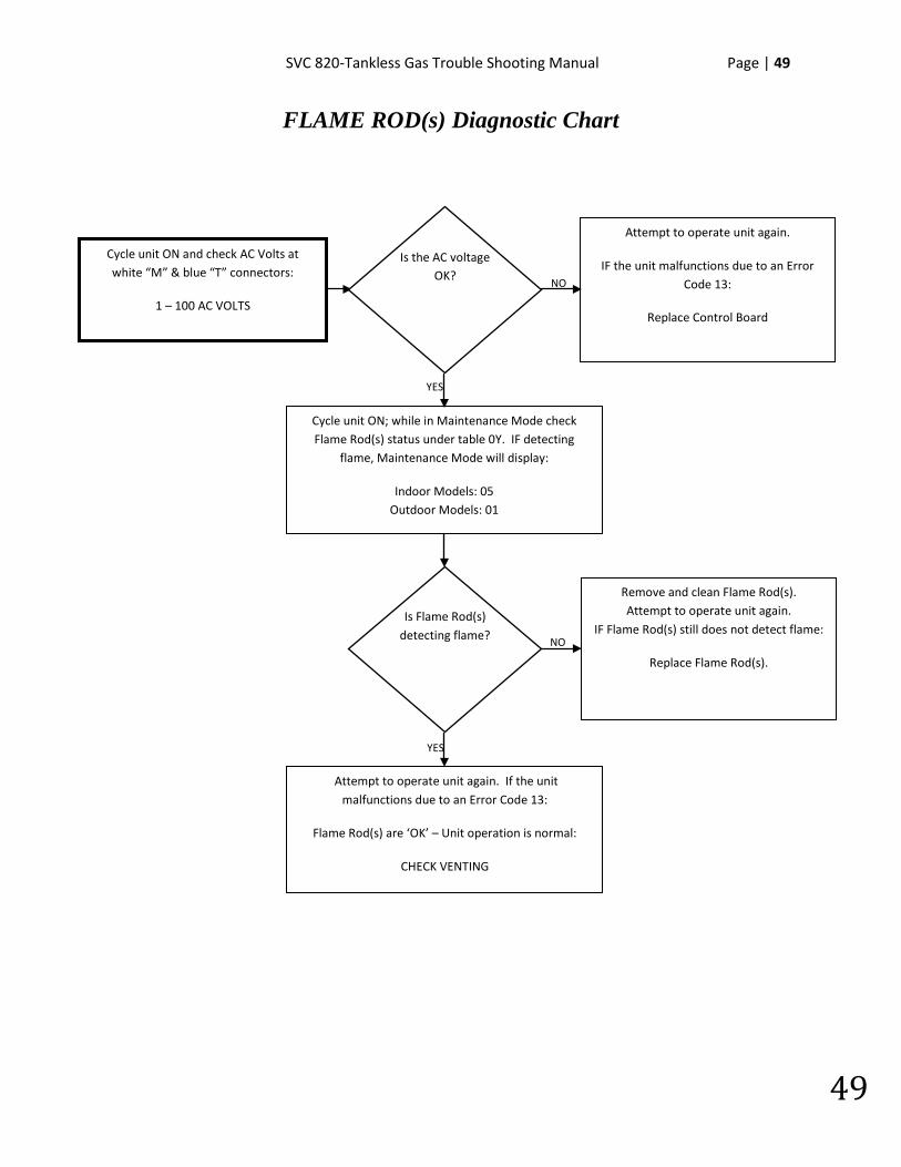
FLAME ROD(s) Diagnostic Chart
NO
YES
YES
NO
Cycle unit ON and check AC Volts at white “M” & blue “T” connectors:
1 – 100 AC VOLTS
Is the AC voltage OK?
Attempt to operate unit again.
IF the unit malfunctions due to an Error Code 13:
Replace Control Board
Is Flame Rod(s) detecting flame?
Cycle unit ON; while in Maintenance Mode check Flame Rod(s) status under table 0Y. IF detecting
flame, Maintenance Mode will display:
Indoor Models: 05 Outdoor Models: 01
Attempt to operate unit again. If the unit malfunctions due to an Error Code 13:
Flame Rod(s) are ‘OK’ – Unit operation is normal:
CHECK VENTING
Remove and clean Flame Rod(s). Attempt to operate unit again.
IF Flame Rod(s) still does not detect flame:
Replace Flame Rod(s).
50 | Page SVC 820 Tankless Gas Trouble Shooting Manual
50
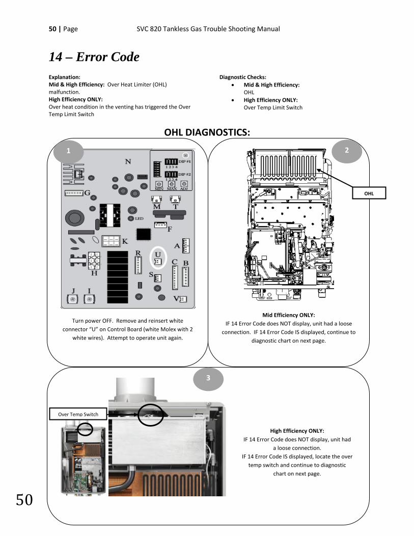
14 – Error Code Explanation: Mid & High Efficiency: Over Heat Limiter (OHL) malfunction. High Efficiency ONLY: Over heat condition in the venting has triggered the Over Temp Limit Switch
Diagnostic Checks: • Mid & High Efficiency:
OHL • High Efficiency ONLY:
Over Temp Limit Switch
OHL DIAGNOSTICS:
Mid Efficiency ONLY: IF 14 Error Code does NOT display, unit had a loose
connection. IF 14 Error Code IS displayed, continue to diagnostic chart on next page.
Turn power OFF. Remove and reinsert white connector “U” on Control Board (white Molex with 2
white wires). Attempt to operate unit again.
1 2
3
High Efficiency ONLY: IF 14 Error Code does NOT display, unit had
a loose connection. IF 14 Error Code IS displayed, locate the over
temp switch and continue to diagnostic chart on next page.
OHL
Over Temp Switch
SVC 820-Tankless Gas Trouble Shooting Manual Page | 51
51
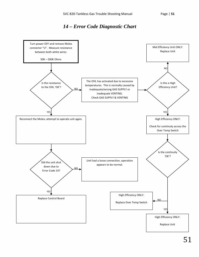
14 – Error Code Diagnostic Chart
NO
High Efficiency ONLY:
Check for continuity across the Over Temp Switch
Turn power OFF and remove Molex connector “U”. Measure resistance
between both white wires:
50K – 500K Ohms
The OHL has activated due to excessive temperatures. This is normally caused by
inadequate/wrong GAS SUPPLY or inadequate VENTING.
Check GAS SUPPLY & VENTING
Unit had a loose connection, operation appears to be normal.
NO
YES
YES
NO
Is the resistance to the OHL ‘OK’?
Did the unit shut down due to
Error Code 14?
Reconnect the Molex; attempt to operate unit again.
Replace Control Board
Is this a High Efficiency Unit?
Mid Efficiency Unit ONLY: Replace Unit
NO
YES
Is the continuity ‘OK’?
YES
High Efficiency ONLY:
Replace Over Temp Switch
High Efficiency ONLY:
Replace Unit

52 | Page SVC 820 Tankless Gas Trouble Shooting Manual
52
NOTES:
________________________________________________________________________________________________________________________________________________________________________________________________________________________________________________________________________________________________________________________________________________________________________________________________________________________________________________________________________________________________________________________________________________________________________________________________________________________________________________________________________________________________________________________________________________________________________________________________________________________________________________________________________________________________________________________________________________________
SVC 820-Tankless Gas Trouble Shooting Manual Page | 53
53
15 – Error Code Explanation: The hot water temperature and/or heat exchanger temperature reached 207 degrees F for more than 15 seconds. IMPORTANT: Inadequate GAS SUPPLY and/or VENTING will create hot spots in the heat exchanger. Diagnostic Checks:
• GAS SUPPLY & VENTING • Sediment Build-Up in Heat Exchanger • Heat Exchanger Temperature Sensor
SEDIMENT BUILD-UP DIAGNOSTICS: Go to Error Code 1L for flushing instructions
HEAT EXCHANGER TEMPERATURE SENSOR DIAGNOSTICS:
Go to Error Code 32 for Heat Exchanger Temperature Sensor diagnostic instructions.
GAS SUPPLY & VENTING **REFER TO USE & CARE MANUAL**
Make sure you have sufficient fuel for the unit to operate properly.
1. Gas Type (LP or Natural Gas) 2. Gas Pressure 3. Gas Pipe Size 4. Gas Flex Line Not To Exceed 36” In Length, has the proper ID (Inside Diameter), and correct BTU rating 5. Gas Regulator 6. Gas Shut Off Valves 7. Air In Gas Line
Visually inspect venting for possible blockage and/or recirculation of exhaust. 1. Approved Venting Materials 2. Approved Vent Terminations 3. Vent Lengths 4. Location Of Vent Termination (Recirculation of exhaust) 5. Blocked Venting 6. Venting Not Sealed Properly
54 | Page SVC 820 Tankless Gas Trouble Shooting Manual
54
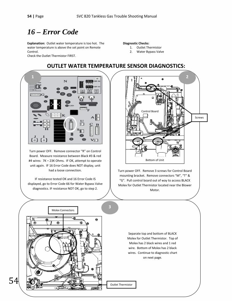
16 – Error Code Explanation: Outlet water temperature is too hot. The water temperature is above the set point on Remote Control. Check the Outlet Thermistor FIRST.
Diagnostic Checks: 1. Outlet Thermistor 2. Water Bypass Valve
OUTLET WATER TEMPERATURE SENSOR DIAGNOSTICS:
Turn power OFF. Remove connector “R” on Control Board. Measure resistance between Black #3 & red #4 wires: 7K – 23K Ohms. IF OK, attempt to operate unit again. IF 16 Error Code does NOT display, unit
had a loose connection.
IF resistance tested OK and 16 Error Code IS displayed, go to Error Code 66 for Water Bypass Valve
diagnostics. IF resistance NOT OK, go to step 2.
Turn power OFF. Remove 3 screws for Control Board mounting bracket. Remove connectors “M”, “T” & “G”. Pull control board out of way to access BLACK
Molex for Outlet Thermistor located near the Blower Motor.
1 2
3
Control Board
Bottom of Unit
Screws
Molex Connectors
Outlet Thermistor
Separate top and bottom of BLACK Molex for Outlet Thermistor. Top of
Molex has 2 black wires and 1 red wire. Bottom of Molex has 2 black wires. Continue to diagnostic chart
on next page.
SVC 820-Tankless Gas Trouble Shooting Manual Page | 55
55
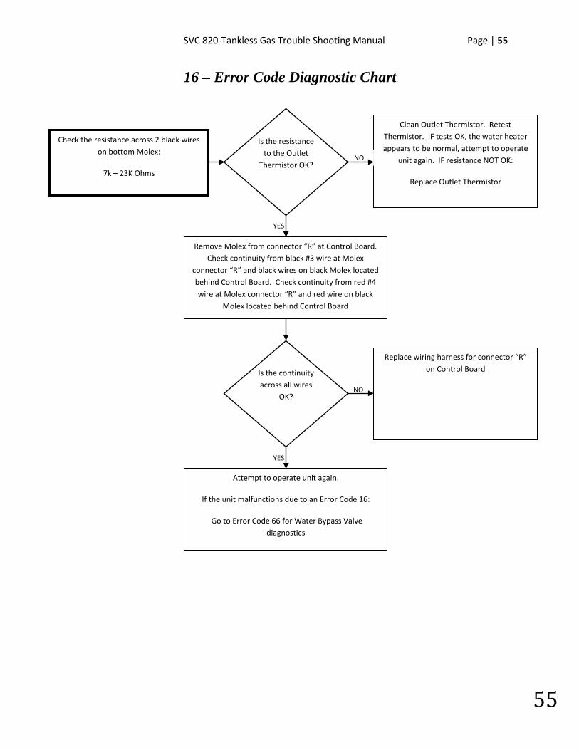
16 – Error Code Diagnostic Chart
Check the resistance across 2 black wires
on bottom Molex:
7k – 23K Ohms
Clean Outlet Thermistor. Retest Thermistor. IF tests OK, the water heater appears to be normal, attempt to operate
unit again. IF resistance NOT OK:
Replace Outlet Thermistor
Replace wiring harness for connector “R” on Control Board
NO
YES
YES
NO
Is the resistance to the Outlet
Thermistor OK?
Is the continuity across all wires
OK?
Remove Molex from connector “R” at Control Board. Check continuity from black #3 wire at Molex
connector “R” and black wires on black Molex located behind Control Board. Check continuity from red #4 wire at Molex connector “R” and red wire on black
Molex located behind Control Board
Attempt to operate unit again.
If the unit malfunctions due to an Error Code 16:
Go to Error Code 66 for Water Bypass Valve diagnostics
56 | Page SVC 820 Tankless Gas Trouble Shooting Manual
56
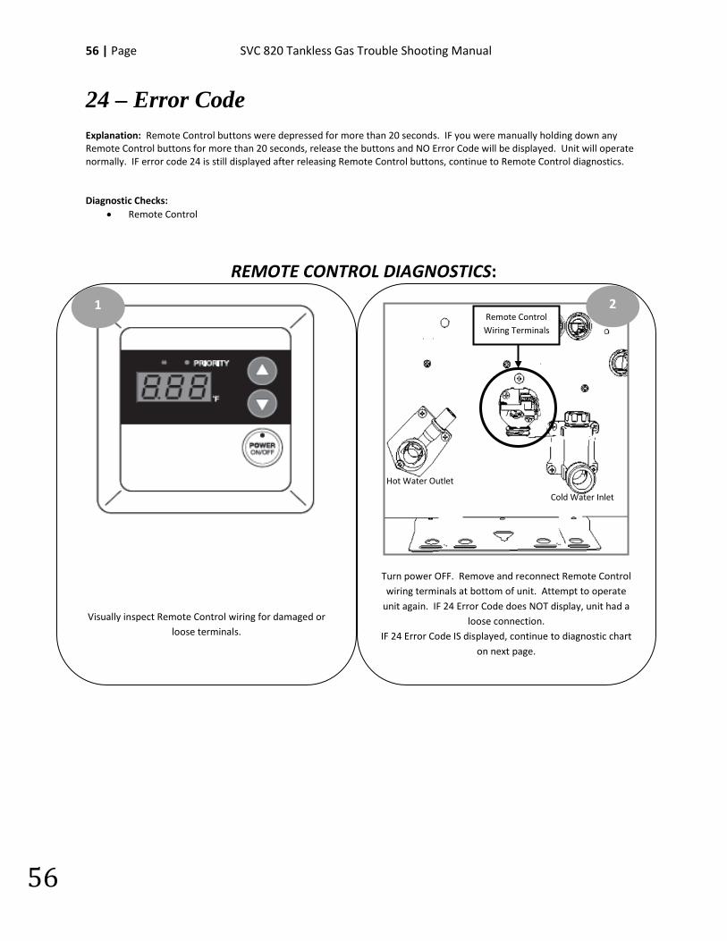
24 – Error Code Explanation: Remote Control buttons were depressed for more than 20 seconds. IF you were manually holding down any Remote Control buttons for more than 20 seconds, release the buttons and NO Error Code will be displayed. Unit will operate normally. IF error code 24 is still displayed after releasing Remote Control buttons, continue to Remote Control diagnostics. Diagnostic Checks:
• Remote Control
REMOTE CONTROL DIAGNOSTICS:
Visually inspect Remote Control wiring for damaged or loose terminals.
1
Turn power OFF. Remove and reconnect Remote Control wiring terminals at bottom of unit. Attempt to operate
unit again. IF 24 Error Code does NOT display, unit had a loose connection.
IF 24 Error Code IS displayed, continue to diagnostic chart on next page.
2
Hot Water Outlet
Cold Water Inlet
Remote Control Wiring Terminals
SVC 820-Tankless Gas Trouble Shooting Manual Page | 57
57
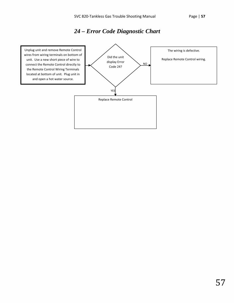
24 – Error Code Diagnostic Chart
YES
NO
Unplug unit and remove Remote Control wires from wiring terminals on bottom of
unit. Use a new short piece of wire to connect the Remote Control directly to the Remote Control Wiring Terminals located at bottom of unit. Plug unit in
and open a hot water source.
Did the unit display Error
Code 24?
The wiring is defective.
Replace Remote Control wiring.
Replace Remote Control

58 | Page SVC 820 Tankless Gas Trouble Shooting Manual
58
NOTES:
________________________________________________________________________________________________________________________________________________________________________________________________________________________________________________________________________________________________________________________________________________________________________________________________________________________________________________________________________________________________________________________________________________________________________________________________________________________________________________________________________________________________________________________________________________________________________________________________________________________________________________________________________________________________________________________________________________________

SVC 820-Tankless Gas Trouble Shooting Manual Page | 59
59
29 – Error Code Explanation: High Efficiency Condensing Units ONLY: Condensate Drain is NOT draining.
Diagnostic Checks:
• Plug not removed from condensate drain • Pinch in condensate drain line • Blockage in condensate drain line • Drain line has unnecessary “P” trap
CONDENSATE DRAIN DIAGNOSTICS:
Ensure you removed the condensate protection plug located at bottom of unit.
1
Check your condensate drain line for internal or external blockage. Make sure drain line is NOT pinched.
2
Drain Line
60 | Page SVC 820 Tankless Gas Trouble Shooting Manual
60
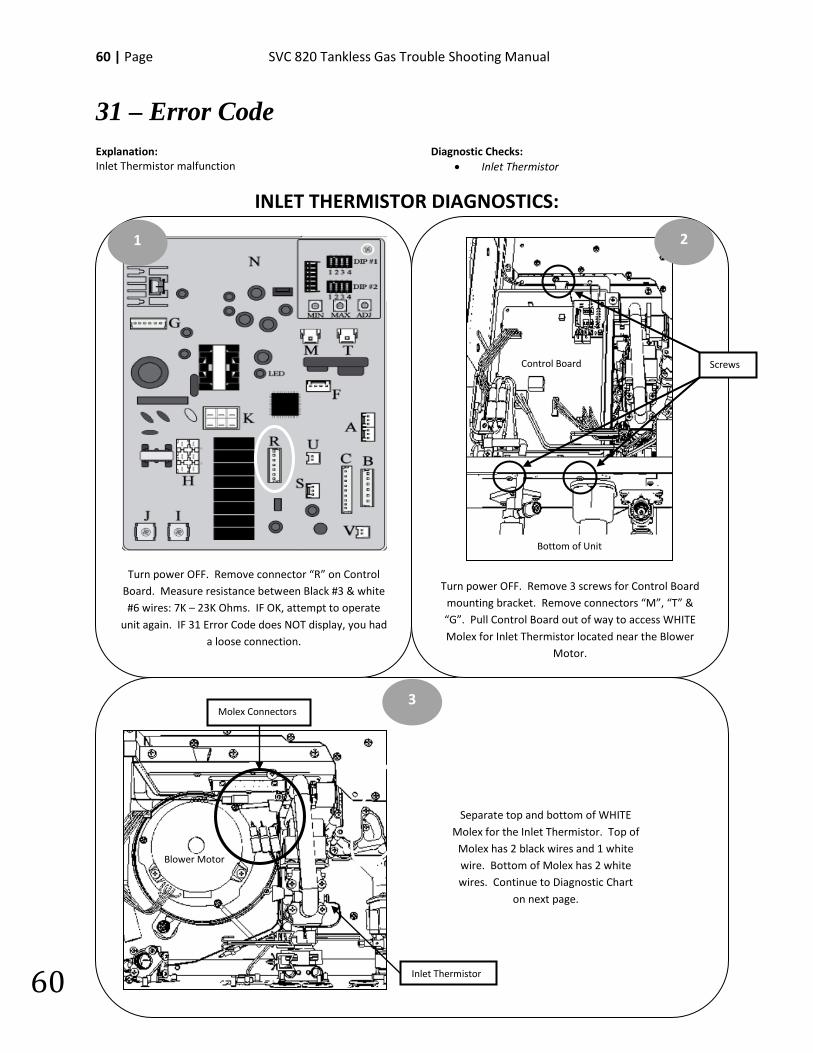
31 – Error Code Explanation: Inlet Thermistor malfunction
Diagnostic Checks: • Inlet Thermistor
INLET THERMISTOR DIAGNOSTICS:
Turn power OFF. Remove 3 screws for Control Board mounting bracket. Remove connectors “M”, “T” & “G”. Pull Control Board out of way to access WHITE Molex for Inlet Thermistor located near the Blower
Motor.
Turn power OFF. Remove connector “R” on Control Board. Measure resistance between Black #3 & white #6 wires: 7K – 23K Ohms. IF OK, attempt to operate
unit again. IF 31 Error Code does NOT display, you had a loose connection.
1 2
3
Separate top and bottom of WHITE Molex for the Inlet Thermistor. Top of
Molex has 2 black wires and 1 white wire. Bottom of Molex has 2 white wires. Continue to Diagnostic Chart
on next page.
Screws
Bottom of Unit
Control Board
Blower Motor
Molex Connectors
Inlet Thermistor
SVC 820-Tankless Gas Trouble Shooting Manual Page | 61
61
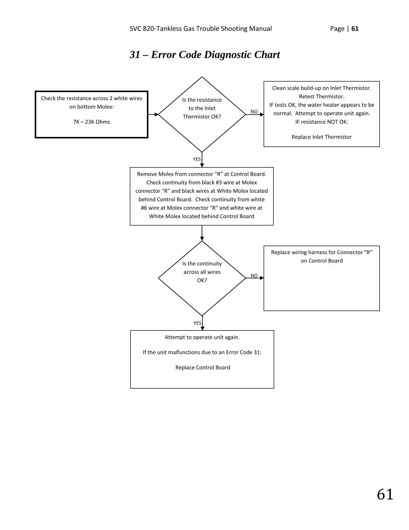
31 – Error Code Diagnostic Chart
NO
NO
Check the resistance across 2 white wires on bottom Molex:
7K – 23K Ohms
Clean scale build-up on Inlet Thermistor. Retest Thermistor.
IF tests OK, the water heater appears to be normal. Attempt to operate unit again.
IF resistance NOT OK:
Replace Inlet Thermistor
Replace wiring harness for Connector “R” on Control Board
YES
YES
Is the resistance to the Inlet
Thermistor OK?
Is the continuity across all wires
OK?
Remove Molex from connector “R” at Control Board. Check continuity from black #3 wire at Molex
connector “R” and black wires at White Molex located behind Control Board. Check continuity from white #6 wire at Molex connector “R” and white wire at
White Molex located behind Control Board
Attempt to operate unit again.
If the unit malfunctions due to an Error Code 31:
Replace Control Board
62 | Page SVC 820 Tankless Gas Trouble Shooting Manual
62
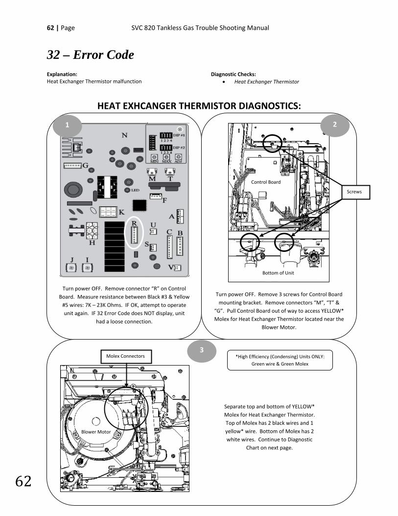
32 – Error Code Explanation: Heat Exchanger Thermistor malfunction
Diagnostic Checks: • Heat Exchanger Thermistor
HEAT EXHCANGER THERMISTOR DIAGNOSTICS:
Turn power OFF. Remove 3 screws for Control Board mounting bracket. Remove connectors “M”, “T” &
“G”. Pull Control Board out of way to access YELLOW* Molex for Heat Exchanger Thermistor located near the
Blower Motor.
Turn power OFF. Remove connector “R” on Control Board. Measure resistance between Black #3 & Yellow
#5 wires: 7K – 23K Ohms. IF OK, attempt to operate unit again. IF 32 Error Code does NOT display, unit
had a loose connection.
1 2
3
Separate top and bottom of YELLOW* Molex for Heat Exchanger Thermistor. Top of Molex has 2 black wires and 1 yellow* wire. Bottom of Molex has 2 white wires. Continue to Diagnostic
Chart on next page.
Screws
Bottom of Unit
Control Board
Molex Connectors
Blower Motor
*High Efficiency (Condensing) Units ONLY: Green wire & Green Molex
SVC 820-Tankless Gas Trouble Shooting Manual Page | 63
63
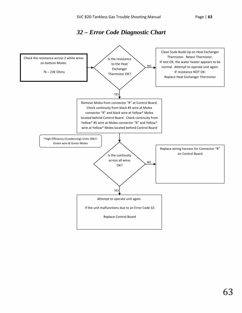
32 – Error Code Diagnostic Chart
Check the resistance across 2 white wires
on bottom Molex:
7k – 23K Ohms
Replace wiring harness for Connector “R” on Control Board
Clean Scale Build-Up on Heat Exchanger Thermistor. Retest Thermistor.
IF test OK, the water heater appears to be normal. Attempt to operate unit again.
IF resistance NOT OK: Replace Heat Exchanger Thermistor
NO
YES
YES
NO
Is the resistance to the Heat Exchanger
Thermistor OK?
Is the continuity across all wires
OK?
Remove Molex from connector “R” at Control Board. Check continuity from black #3 wire at Molex
connector “R” and black wire at Yellow* Molex located behind Control Board. Check continuity from Yellow* #5 wire at Molex connector “R” and Yellow* wire at Yellow* Molex located behind Control Board
Attempt to operate unit again.
If the unit malfunctions due to an Error Code 32:
Replace Control Board
*High Efficiency (Condensing) Units ONLY: Green wire & Green Molex
64 | Page SVC 820 Tankless Gas Trouble Shooting Manual
64
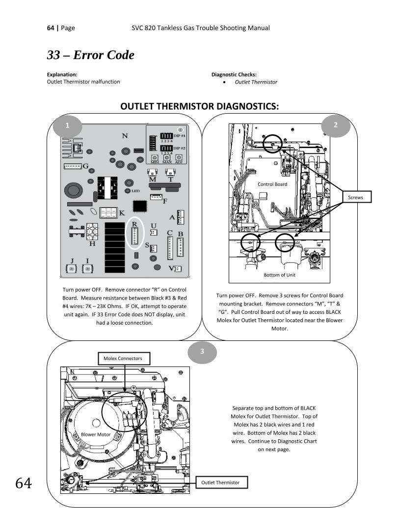
33 – Error Code Explanation: Outlet Thermistor malfunction
Diagnostic Checks: • Outlet Thermistor
OUTLET THERMISTOR DIAGNOSTICS:
Turn power OFF. Remove 3 screws for Control Board mounting bracket. Remove connectors “M”, “T” & “G”. Pull Control Board out of way to access BLACK
Molex for Outlet Thermistor located near the Blower Motor.
Turn power OFF. Remove connector “R” on Control Board. Measure resistance between Black #3 & Red #4 wires: 7K – 23K Ohms. IF OK, attempt to operate unit again. IF 33 Error Code does NOT display, unit
had a loose connection.
1 2
3
Separate top and bottom of BLACK Molex for Outlet Thermistor. Top of
Molex has 2 black wires and 1 red wire. Bottom of Molex has 2 black
wires. Continue to Diagnostic Chart on next page.
Screws
Bottom of Unit
Control Board
Blower Motor
Molex Connectors
Outlet Thermistor
SVC 820-Tankless Gas Trouble Shooting Manual Page | 65
65
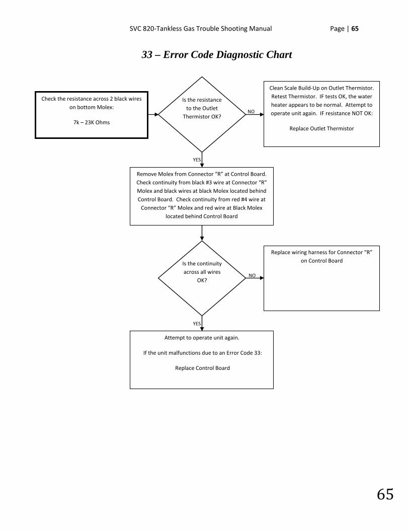
33 – Error Code Diagnostic Chart
Check the resistance across 2 black wires
on bottom Molex:
7k – 23K Ohms
Clean Scale Build-Up on Outlet Thermistor. Retest Thermistor. IF tests OK, the water heater appears to be normal. Attempt to operate unit again. IF resistance NOT OK:
Replace Outlet Thermistor
Replace wiring harness for Connector “R” on Control Board
NO
YES
YES
NO
Is the resistance to the Outlet
Thermistor OK?
Is the continuity across all wires
OK?
Remove Molex from Connector “R” at Control Board. Check continuity from black #3 wire at Connector “R” Molex and black wires at black Molex located behind Control Board. Check continuity from red #4 wire at
Connector “R” Molex and red wire at Black Molex located behind Control Board
Attempt to operate unit again.
If the unit malfunctions due to an Error Code 33:
Replace Control Board
66 | Page SVC 820 Tankless Gas Trouble Shooting Manual
66
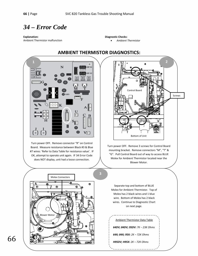
34 – Error Code Explanation: Ambient Thermistor malfunction
Diagnostic Checks: • Ambient Thermistor
AMBIENT THERMISTOR DIAGNOSTICS:
Turn power OFF. Remove 3 screws for Control Board mounting bracket. Remove connectors “M”, “T” & “G”. Pull Control Board out of way to access BLUE
Molex for Ambient Thermistor located near the Blower Motor.
Turn power OFF. Remove connector “R” on Control Board. Measure resistance between Black #3 & Blue #7 wires: ‘Refer to Data Table for resistance value’. IF OK, attempt to operate unit again. IF 34 Error Code
does NOT display, unit had a loose connection.
1 2
3
Separate top and bottom of BLUE Molex for Ambient Thermistor. Top of
Molex has 2 black wires and 1 blue wire. Bottom of Molex has 2 black
wires. Continue to Diagnostic Chart on next page.
Screws
Bottom of Unit
Control Board
Blower Motor
Molex Connectors
Ambient Thermistor Data Table
64DV; 84DV; 95DV: 7K – 23K Ohms
64X; 84X; 95X: 2K – 72K Ohms
H95DV; H95X: 2K – 72K Ohms
SVC 820-Tankless Gas Trouble Shooting Manual Page | 67
67
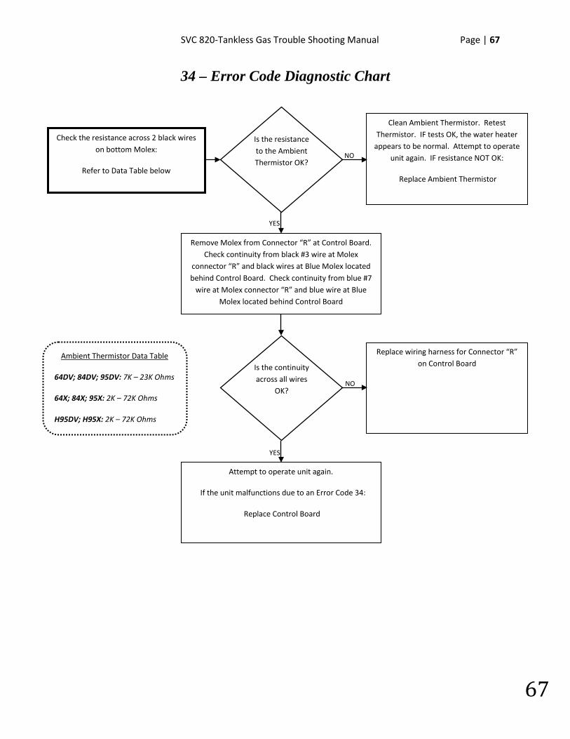
34 – Error Code Diagnostic Chart
Check the resistance across 2 black wires
on bottom Molex:
Refer to Data Table below
Replace wiring harness for Connector “R” on Control Board
Clean Ambient Thermistor. Retest Thermistor. IF tests OK, the water heater
appears to be normal. Attempt to operate unit again. IF resistance NOT OK:
Replace Ambient Thermistor
NO
YES
YES
NO
Is the resistance to the Ambient Thermistor OK?
Is the continuity across all wires
OK?
Remove Molex from Connector “R” at Control Board. Check continuity from black #3 wire at Molex
connector “R” and black wires at Blue Molex located behind Control Board. Check continuity from blue #7
wire at Molex connector “R” and blue wire at Blue Molex located behind Control Board
Attempt to operate unit again.
If the unit malfunctions due to an Error Code 34:
Replace Control Board
Ambient Thermistor Data Table
64DV; 84DV; 95DV: 7K – 23K Ohms
64X; 84X; 95X: 2K – 72K Ohms
H95DV; H95X: 2K – 72K Ohms
68 | Page SVC 820 Tankless Gas Trouble Shooting Manual
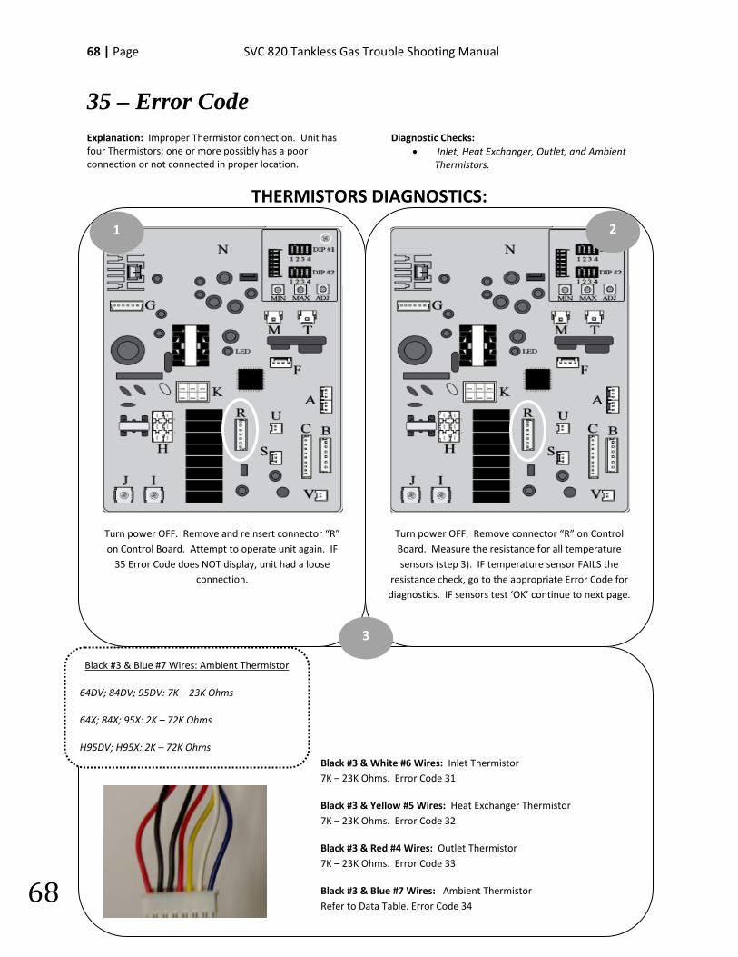
68
35 – Error Code Explanation: Improper Thermistor connection. Unit has four Thermistors; one or more possibly has a poor connection or not connected in proper location.
Diagnostic Checks: • Inlet, Heat Exchanger, Outlet, and Ambient
Thermistors.
THERMISTORS DIAGNOSTICS:
Turn power OFF. Remove connector “R” on Control Board. Measure the resistance for all temperature sensors (step 3). IF temperature sensor FAILS the
resistance check, go to the appropriate Error Code for diagnostics. IF sensors test ‘OK’ continue to next page.
Turn power OFF. Remove and reinsert connector “R” on Control Board. Attempt to operate unit again. IF
35 Error Code does NOT display, unit had a loose connection.
1 2
3
Black #3 & Blue #7 Wires: Ambient Thermistor
64DV; 84DV; 95DV: 7K – 23K Ohms
64X; 84X; 95X: 2K – 72K Ohms
H95DV; H95X: 2K – 72K Ohms
Black #3 & White #6 Wires: Inlet Thermistor 7K – 23K Ohms. Error Code 31
Black #3 & Yellow #5 Wires: Heat Exchanger Thermistor 7K – 23K Ohms. Error Code 32
Black #3 & Red #4 Wires: Outlet Thermistor 7K – 23K Ohms. Error Code 33
Black #3 & Blue #7 Wires: Ambient Thermistor Refer to Data Table. Error Code 34
SVC 820-Tankless Gas Trouble Shooting Manual Page | 69
69
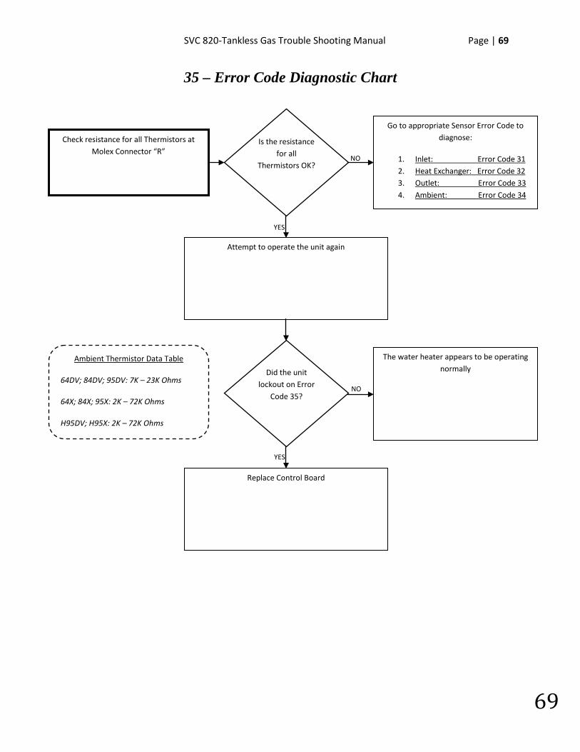
35 – Error Code Diagnostic Chart
Check resistance for all Thermistors at
Molex Connector “R”
NO
YES
YES
NO
Is the resistance for all
Thermistors OK?
Go to appropriate Sensor Error Code to diagnose:
1. Inlet: Error Code 31 2. Heat Exchanger: Error Code 32 3. Outlet: Error Code 33 4. Ambient: Error Code 34
Did the unit lockout on Error
Code 35?
Attempt to operate the unit again
Replace Control Board
The water heater appears to be operating normally
Ambient Thermistor Data Table
64DV; 84DV; 95DV: 7K – 23K Ohms
64X; 84X; 95X: 2K – 72K Ohms
H95DV; H95X: 2K – 72K Ohms
70 | Page SVC 820 Tankless Gas Trouble Shooting Manual
70
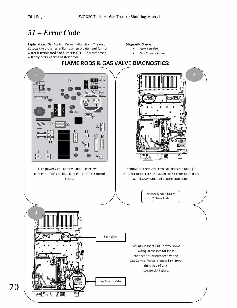
51 – Error Code Explanation: Gas Control Valve malfunction. The unit detects the presence of flame when the demand for hot water is terminated and burner is OFF. This error code will only occur at time of shut down.
Diagnostic Checks: • Flame Rods(s) • Gas Control Valve
FLAME RODS & GAS VALVE DIAGNOSTICS:
Remove and reinsert terminals on Fame Rod(s)*. Attempt to operate unit again. IF 51 Error Code does
NOT display, unit had a loose connection.
Turn power OFF. Remove and reinsert white connector “M” and blue connector “T” on Control
Board.
1 2
3
*Indoor Models ONLY: 2 Flame Rods
Visually inspect Gas Control Valve wiring harnesses for loose
connections or damaged wiring. Gas Control Valve is located on lower
right side of unit. Locate sight glass.
Sight Glass
Gas Control Valve
SVC 820-Tankless Gas Trouble Shooting Manual Page | 71
71
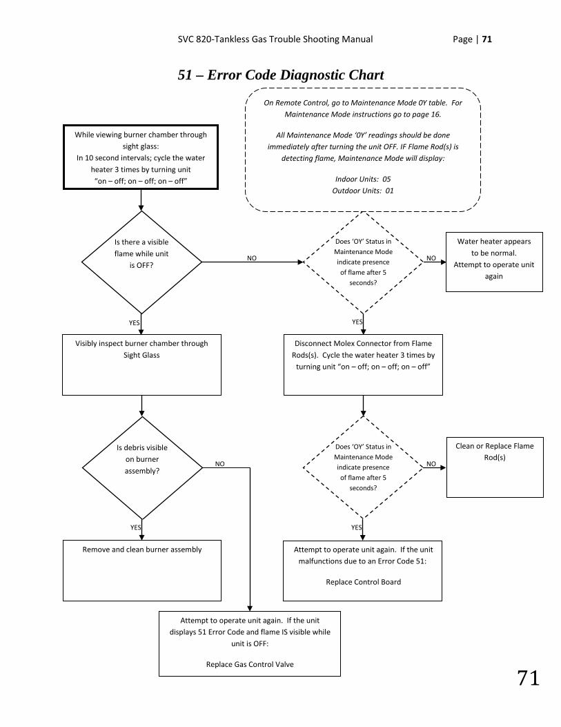
51 – Error Code Diagnostic Chart
NO
Clean or Replace Flame Rod(s)
Water heater appears to be normal.
Attempt to operate unit again
YES
NO
YES
NO
While viewing burner chamber through sight glass:
In 10 second intervals; cycle the water heater 3 times by turning unit “on – off; on – off; on – off”
Is there a visible flame while unit
is OFF?
Visibly inspect burner chamber through Sight Glass
Is debris visible on burner assembly?
YES
Remove and clean burner assembly
NO
Disconnect Molex Connector from Flame Rods(s). Cycle the water heater 3 times by
turning unit “on – off; on – off; on – off”
Does ‘OY’ Status in Maintenance Mode indicate presence of flame after 5
seconds?
Does ‘OY’ Status in Maintenance Mode indicate presence of flame after 5
seconds?
YES
Attempt to operate unit again. If the unit malfunctions due to an Error Code 51:
Replace Control Board
On Remote Control, go to Maintenance Mode 0Y table. For Maintenance Mode instructions go to page 16.
All Maintenance Mode ‘0Y’ readings should be done immediately after turning the unit OFF. IF Flame Rod(s) is
detecting flame, Maintenance Mode will display:
Indoor Units: 05 Outdoor Units: 01
Attempt to operate unit again. If the unit displays 51 Error Code and flame IS visible while
unit is OFF:
Replace Gas Control Valve
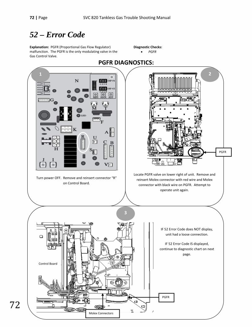
72 | Page SVC 820 Tankless Gas Trouble Shooting Manual
72
52 – Error Code Explanation: PGFR (Proportional Gas Flow Regulator) malfunction. The PGFR is the only modulating valve in the Gas Control Valve.
Diagnostic Checks: • PGFR
PGFR DIAGNOSTICS:
Locate PGFR valve on lower right of unit. Remove and reinsert Molex connector with red wire and Molex
connector with black wire on PGFR. Attempt to operate unit again.
Turn power OFF. Remove and reinsert connector “R” on Control Board.
1 2
3
IF 52 Error Code does NOT display, unit had a loose connection.
IF 52 Error Code IS displayed, continue to diagnostic chart on next
page.
PGFR
Control Board
PGFR
Molex Connectors
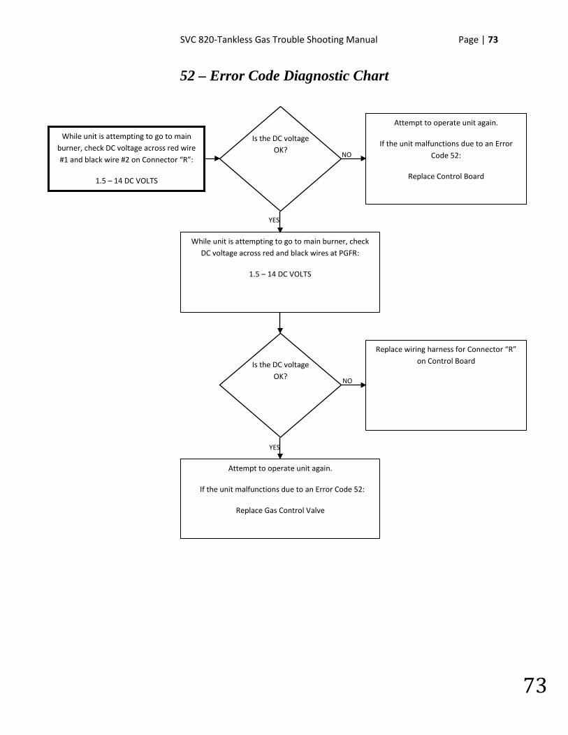
SVC 820-Tankless Gas Trouble Shooting Manual Page | 73
73
52 – Error Code Diagnostic Chart
NO
YES
YES
NO
While unit is attempting to go to main burner, check DC voltage across red wire #1 and black wire #2 on Connector “R”:
1.5 – 14 DC VOLTS
Is the DC voltage OK?
Attempt to operate unit again.
If the unit malfunctions due to an Error Code 52:
Replace Control Board
Is the DC voltage OK?
While unit is attempting to go to main burner, check DC voltage across red and black wires at PGFR:
1.5 – 14 DC VOLTS
Attempt to operate unit again.
If the unit malfunctions due to an Error Code 52:
Replace Gas Control Valve
Replace wiring harness for Connector “R” on Control Board
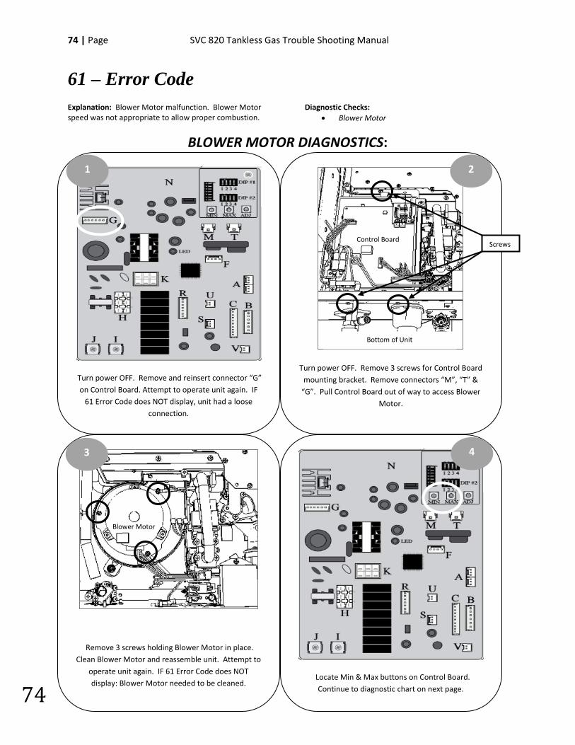
74 | Page SVC 820 Tankless Gas Trouble Shooting Manual
74
61 – Error Code Explanation: Blower Motor malfunction. Blower Motor speed was not appropriate to allow proper combustion.
Diagnostic Checks: • Blower Motor
BLOWER MOTOR DIAGNOSTICS:
Locate Min & Max buttons on Control Board. Continue to diagnostic chart on next page.
Turn power OFF. Remove 3 screws for Control Board mounting bracket. Remove connectors “M”, “T” &
“G”. Pull Control Board out of way to access Blower Motor.
Turn power OFF. Remove and reinsert connector “G” on Control Board. Attempt to operate unit again. IF
61 Error Code does NOT display, unit had a loose connection.
Remove 3 screws holding Blower Motor in place. Clean Blower Motor and reassemble unit. Attempt to
operate unit again. IF 61 Error Code does NOT display: Blower Motor needed to be cleaned.
1 2
4 3
Blower Motor
Screws Control Board
Bottom of Unit

SVC 820-Tankless Gas Trouble Shooting Manual Page | 75
75
61 – Error Code Diagnostic Chart
YES NO
NO
YES
YES
NO
Test DC voltage across black and red wires on Molex connector “G”:
144 – 192 DC VOLTS
Is the DC voltage OK?
Remove and reinsert connector “G”. Attempt to operate unit again.
If the unit malfunctions due to an Error Code 61:
Replace Control Board
Is the DC voltage OK?
Press and hold down “MAX” button on Control Board to activate Blower Motor. While Blower is running,
test DC voltage across black and white wires on Molex connector “G”:
12 – 18 DC VOLTS
Press and hold down “MAX” button on Control Board to activate Blower Motor. While Blower is running,
test DC voltage across black and blue wires on Molex connector “G”:
4 – 10 DC VOLTS
Remove and reinsert connector “G”. Attempt to operate unit again.
If the unit malfunctions due to an Error Code 61:
Replace Control Board
Is the DC voltage OK?
Replace Blower Motor
Attempt to operate unit again.
If the unit malfunctions due to an Error Code 61:
Replace Control Board
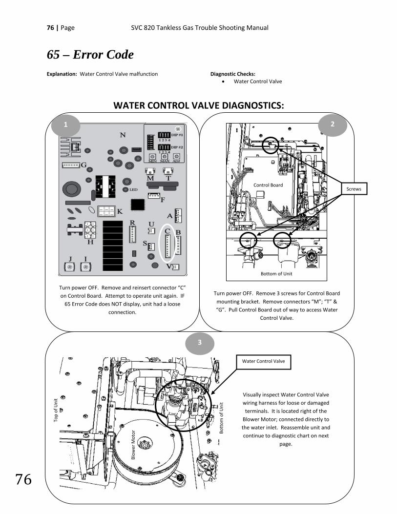
76 | Page SVC 820 Tankless Gas Trouble Shooting Manual
76
65 – Error Code Explanation: Water Control Valve malfunction
Diagnostic Checks: • Water Control Valve
WATER CONTROL VALVE DIAGNOSTICS:
Turn power OFF. Remove 3 screws for Control Board mounting bracket. Remove connectors “M”; “T” & “G”. Pull Control Board out of way to access Water
Control Valve.
Turn power OFF. Remove and reinsert connector “C” on Control Board. Attempt to operate unit again. IF
65 Error Code does NOT display, unit had a loose connection.
1 2
3
Visually inspect Water Control Valve wiring harness for loose or damaged terminals. It is located right of the
Blower Motor; connected directly to the water inlet. Reassemble unit and continue to diagnostic chart on next
page.
Screws
Bottom of Unit
Control Board
Blow
er M
otor
Top
of U
nit
Bott
om o
f Uni
t
Water Control Valve
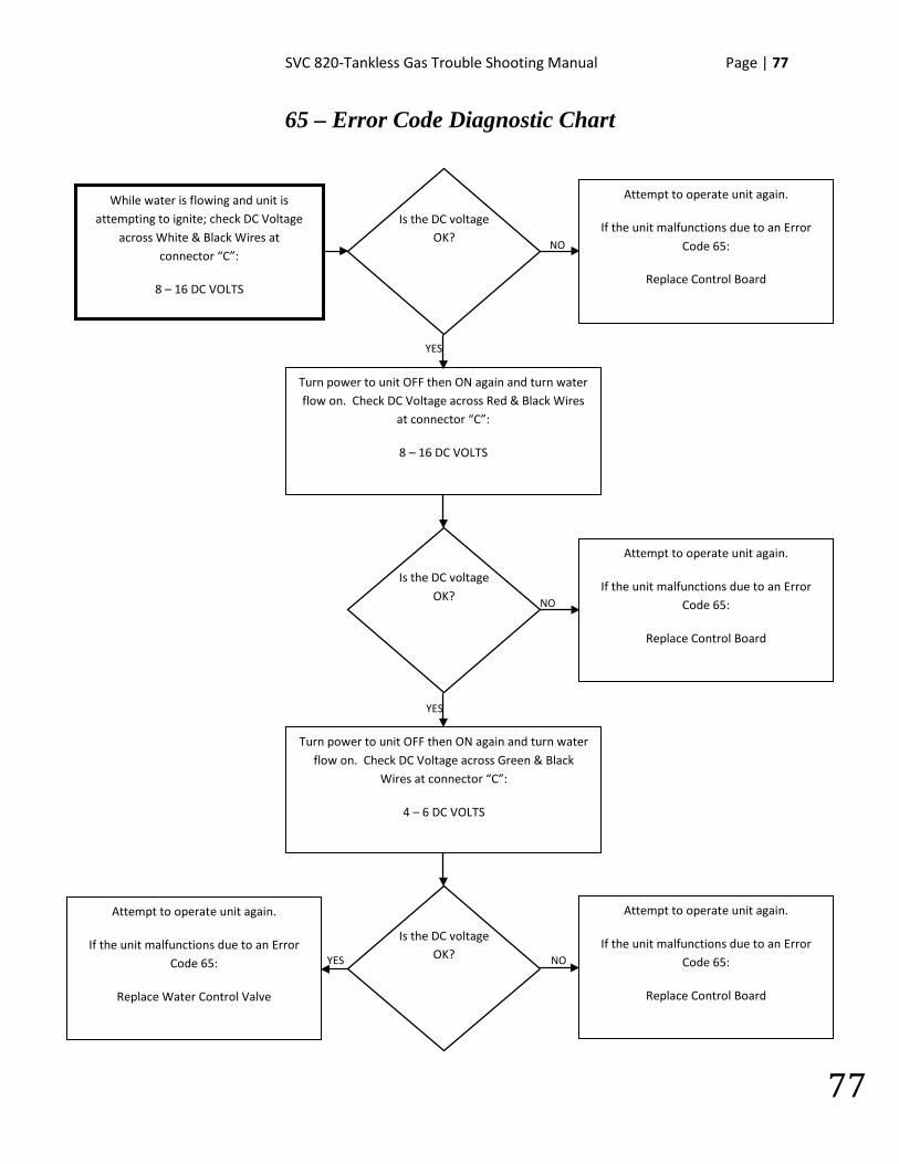
SVC 820-Tankless Gas Trouble Shooting Manual Page | 77
77
65 – Error Code Diagnostic Chart
YES
NO
YES
YES
NO
While water is flowing and unit is attempting to ignite; check DC Voltage
across White & Black Wires at connector “C”:
8 – 16 DC VOLTS
Is the DC voltage OK?
Attempt to operate unit again.
If the unit malfunctions due to an Error Code 65:
Replace Control Board
Is the DC voltage OK?
Turn power to unit OFF then ON again and turn water flow on. Check DC Voltage across Red & Black Wires
at connector “C”:
8 – 16 DC VOLTS
Turn power to unit OFF then ON again and turn water flow on. Check DC Voltage across Green & Black
Wires at connector “C”:
4 – 6 DC VOLTS
Attempt to operate unit again.
If the unit malfunctions due to an Error Code 65:
Replace Control Board
Is the DC voltage OK? NO
Attempt to operate unit again.
If the unit malfunctions due to an Error Code 65:
Replace Control Board
Attempt to operate unit again.
If the unit malfunctions due to an Error Code 65:
Replace Water Control Valve
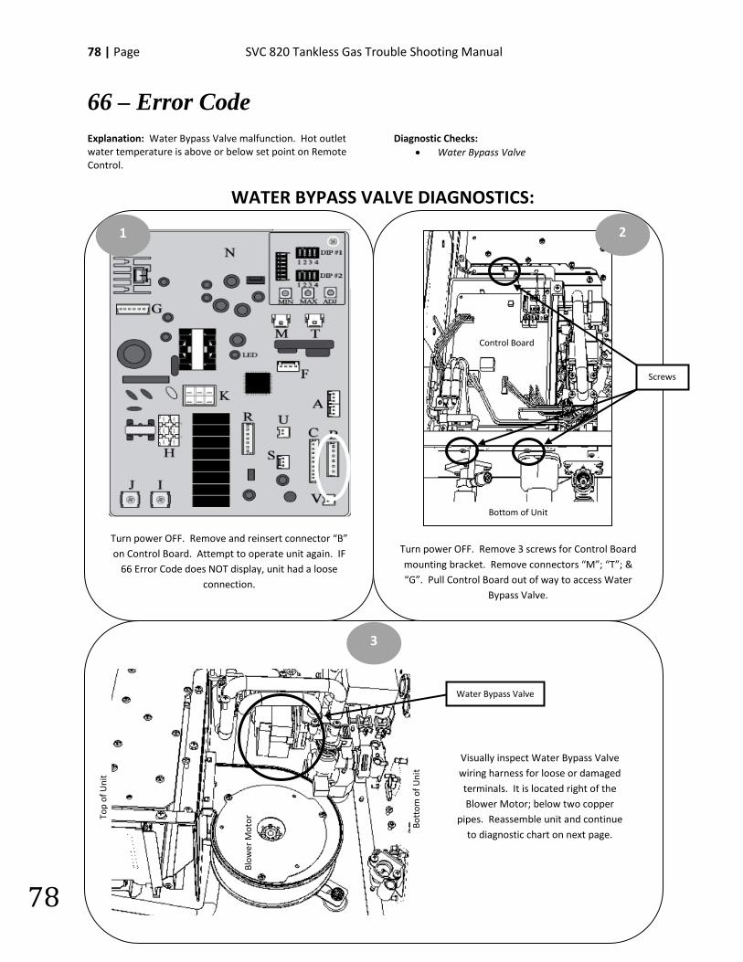
78 | Page SVC 820 Tankless Gas Trouble Shooting Manual
78
66 – Error Code Explanation: Water Bypass Valve malfunction. Hot outlet water temperature is above or below set point on Remote Control.
Diagnostic Checks: • Water Bypass Valve
WATER BYPASS VALVE DIAGNOSTICS:
•
Turn power OFF. Remove 3 screws for Control Board mounting bracket. Remove connectors “M”; “T”; & “G”. Pull Control Board out of way to access Water
Bypass Valve.
Turn power OFF. Remove and reinsert connector “B” on Control Board. Attempt to operate unit again. IF
66 Error Code does NOT display, unit had a loose connection.
1 2
3
Visually inspect Water Bypass Valve wiring harness for loose or damaged terminals. It is located right of the Blower Motor; below two copper
pipes. Reassemble unit and continue to diagnostic chart on next page.
Screws
Blow
er M
otor
Top
of U
nit
Bott
om o
f Uni
t
Water Bypass Valve
Control Board
Bottom of Unit
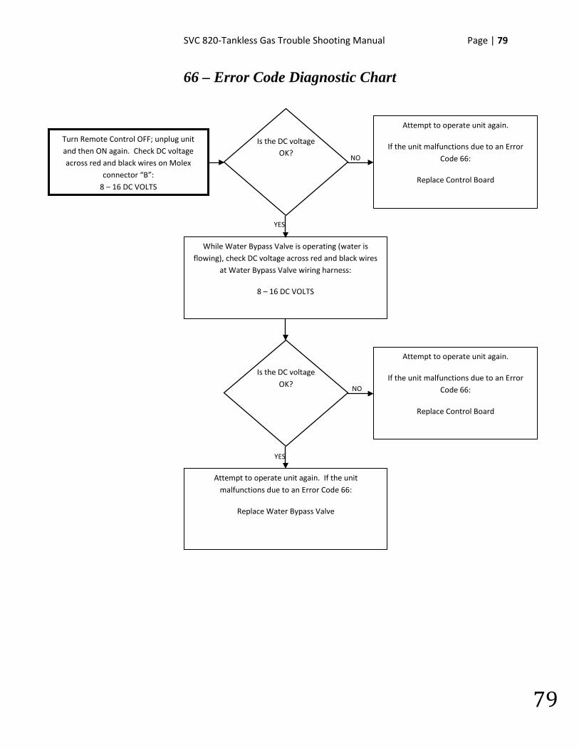
SVC 820-Tankless Gas Trouble Shooting Manual Page | 79
79
66 – Error Code Diagnostic Chart
NO
YES
YES
NO
Turn Remote Control OFF; unplug unit and then ON again. Check DC voltage across red and black wires on Molex
connector “B”: 8 – 16 DC VOLTS
Is the DC voltage OK?
Attempt to operate unit again.
If the unit malfunctions due to an Error Code 66:
Replace Control Board
Is the DC voltage OK?
While Water Bypass Valve is operating (water is flowing), check DC voltage across red and black wires
at Water Bypass Valve wiring harness:
8 – 16 DC VOLTS
Attempt to operate unit again. If the unit malfunctions due to an Error Code 66:
Replace Water Bypass Valve
Attempt to operate unit again.
If the unit malfunctions due to an Error Code 66:
Replace Control Board
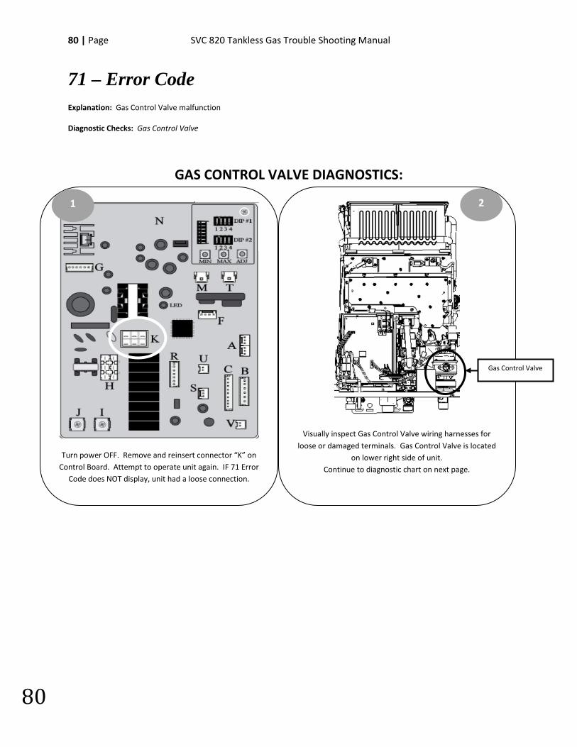
80 | Page SVC 820 Tankless Gas Trouble Shooting Manual
80
71 – Error Code Explanation: Gas Control Valve malfunction Diagnostic Checks: Gas Control Valve
GAS CONTROL VALVE DIAGNOSTICS:
Turn power OFF. Remove and reinsert connector “K” on Control Board. Attempt to operate unit again. IF 71 Error
Code does NOT display, unit had a loose connection.
1
Visually inspect Gas Control Valve wiring harnesses for loose or damaged terminals. Gas Control Valve is located
on lower right side of unit. Continue to diagnostic chart on next page.
2
Gas Control Valve

SVC 820-Tankless Gas Trouble Shooting Manual Page | 81
81
71 – Error Code Diagnostic Chart
YES
NO
While unit is attempting to go to ignite, check DC voltage across yellow and black
wires on Molex connector “K”:
75 – 100 DC VOLTS
Is the DC voltage OK?
Attempt to operate again.
If the unit malfunctions due to an Error Code 71:
Replace Control Board
Reset the water heater and attempt to operate again. If the unit malfunctions due to an Error Code 71:
Replace Gas Control Valve
82 | Page SVC 820 Tankless Gas Trouble Shooting Manual
82
72 – Error Code Explanation: Flame Rod(s) malfunction. Flame Rod(s) is detecting the presence of flame BEFORE igniter is activated.
Diagnostic Checks: • Flame Rod(s) • Gas Control Valve
FLAME ROD(s) & GAS CONTROL VALVE DIAGNOSTICS:
Remove and reinsert terminals on Flame Rod(s)*. Attempt to operate unit again. IF 72 Error Code does
NOT display, unit had a loose connection.
Turn power OFF. Remove and reinsert white connector “M” and blue connector “T” on Control
Board.
1 2
Flame Rod(s)*
*Indoor Units ONLY: 2 Flame Rods
Visually inspect Gas Control Valve wiring harnesses for loose
connections or damaged wiring. Gas Control Valve is located on
lower right side of unit. Locate Sight Glass.
Sight Glass
Gas Control Valve
3
SVC 820-Tankless Gas Trouble Shooting Manual Page | 83
83
72 – Error Code Diagnostic Chart
NO
Clean or Replace Flame Rod(s)
Water heater appears to be normal.
Attempt to operate again
YES
NO
YES
NO
Turn power OFF. Unplug unit and plug back in. Turn power ON. While viewing burner chamber through sight glass, turn on water flow to begin ignition sequence
Is there a visible flame before Igniter Rod
sparks?
Visibly inspect burner chamber through sight glass
Is debris visible on burner assembly?
YES
Remove and clean burner assembly
NO
Turn power OFF. Unplug unit. Disconnect Molex connector(s) from Flame Rod(s).
Plug unit in. Turn power ON. Turn water flow ON to begin ignition sequence
Does ‘OY’ Status in Maintenance Mode indicate presence
of flame?
Does ‘OY’ Status in Maintenance Mode indicate presence
of flame?
YES
Attempt to operate again. If unit displays 72 Error Code:
Replace Control Board
On Remote Control, go to Maintenance Mode 0Y table. For Maintenance Mode instructions go to page 16.
All Maintenance Mode ‘0Y’ readings should be done immediately after turning the unit ON. IF flame sensor IS detecting flame, Maintenance Mode will display:
Indoor Units: 05 Outdoor Units: 01
Attempt to operate again. If unit displays 72 Error Code and flame IS visible while unit is OFF:
Replace Gas Control Valve
84 | Page SVC 820 Tankless Gas Trouble Shooting Manual
84
76 – Error Code Explanation: Communication Fault with Remote Control. Remote Control is not communicating with Control Board
Diagnostic Checks: • Remote Control • Wiring
REMOTE THERMOSTAT DIAGNOSTICS:
Visually inspect Remote Control wiring for damaged or loose terminals.
1
Turn power OFF. Remove and reconnect Remote Control wiring terminals at bottom of unit. Attempt to operate
unit again. IF 76 Error Code does NOT display, unit had a loose connection.
IF 76 Error Code IS displayed, continue to diagnostic chart on next page.
2
Hot Water Outlet
Cold Water Inlet
Remote Control Wiring Terminals
SVC 820-Tankless Gas Trouble Shooting Manual Page | 85
85
76 – Error Code Diagnostic Chart
NO
YES
YES
NO
Unplug unit and remove Remote Thermostat wires from wiring terminals on bottom of unit. Plug unit in and open
a hot water source.
Did the unit go to main burner?
Attempt to operate unit again. If the unit malfunctions due to an Error Code 76:
Replace Remote Control
Did the unit go to main burner?
Unplug unit. Use a short piece of new thermostat wire to connect the Remote Control directly to
Remote Control wiring terminals at bottom of unit.
Plug unit in and open a hot water source.
The wiring is defective. Replace Remote Control wiring.
Replace Remote Control
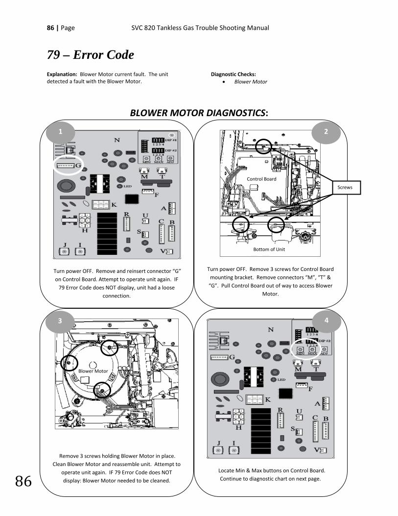
86 | Page SVC 820 Tankless Gas Trouble Shooting Manual
86
79 – Error Code Explanation: Blower Motor current fault. The unit detected a fault with the Blower Motor.
Diagnostic Checks: • Blower Motor
BLOWER MOTOR DIAGNOSTICS:
Locate Min & Max buttons on Control Board. Continue to diagnostic chart on next page.
Turn power OFF. Remove 3 screws for Control Board mounting bracket. Remove connectors “M”, “T” &
“G”. Pull Control Board out of way to access Blower Motor.
Turn power OFF. Remove and reinsert connector “G” on Control Board. Attempt to operate unit again. IF
79 Error Code does NOT display, unit had a loose connection.
Remove 3 screws holding Blower Motor in place. Clean Blower Motor and reassemble unit. Attempt to
operate unit again. IF 79 Error Code does NOT display: Blower Motor needed to be cleaned.
1 2
4 3
Screws
Blower Motor
Control Board
Bottom of Unit
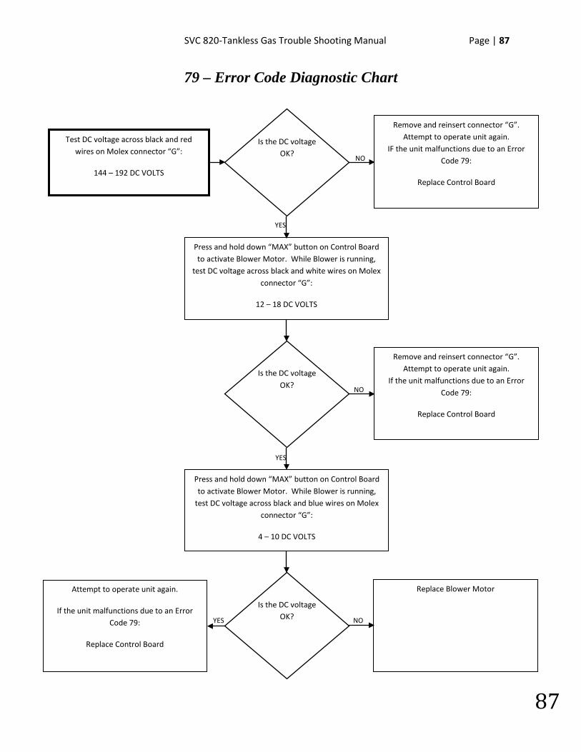
SVC 820-Tankless Gas Trouble Shooting Manual Page | 87
87
79 – Error Code Diagnostic Chart
YES NO
NO
YES
YES
NO
Test DC voltage across black and red wires on Molex connector “G”:
144 – 192 DC VOLTS
Is the DC voltage OK?
Remove and reinsert connector “G”. Attempt to operate unit again.
IF the unit malfunctions due to an Error Code 79:
Replace Control Board
Is the DC voltage OK?
Press and hold down “MAX” button on Control Board to activate Blower Motor. While Blower is running,
test DC voltage across black and white wires on Molex connector “G”:
12 – 18 DC VOLTS
Press and hold down “MAX” button on Control Board to activate Blower Motor. While Blower is running,
test DC voltage across black and blue wires on Molex connector “G”:
4 – 10 DC VOLTS
Remove and reinsert connector “G”. Attempt to operate unit again.
If the unit malfunctions due to an Error Code 79:
Replace Control Board
Is the DC voltage OK?
Replace Blower Motor
Attempt to operate unit again.
If the unit malfunctions due to an Error Code 79:
Replace Control Board
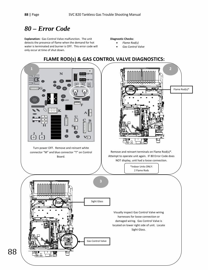
88 | Page SVC 820 Tankless Gas Trouble Shooting Manual
88
80 – Error Code Explanation: Gas Control Valve malfunction. The unit detects the presence of flame when the demand for hot water is terminated and burner is OFF. This error code will only occur at time of shut down.
Diagnostic Checks: • Flame Rod(s) • Gas Control Valve
FLAME ROD(s) & GAS CONTROL VALVE DIAGNOSTICS:
Remove and reinsert terminals on Flame Rod(s)*. Attempt to operate unit again. IF 80 Error Code does
NOT display, unit had a loose connection.
Turn power OFF. Remove and reinsert white connector “M” and blue connector “T” on Control
Board.
1 2
3
Sight Glass
Gas Control Valve
Visually inspect Gas Control Valve wiring harnesses for loose connection or
damaged wiring. Gas Control Valve is located on lower right side of unit. Locate
Sight Glass.
Flame Rod(s)*
*Indoor Units ONLY: 2 Flame Rods
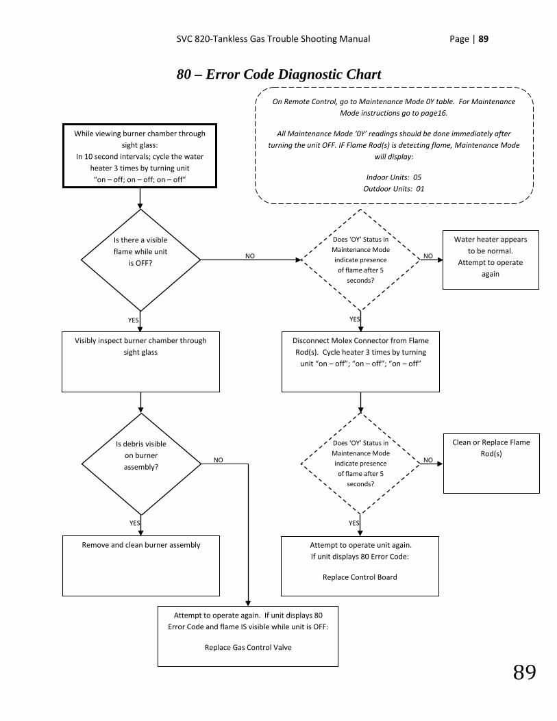
SVC 820-Tankless Gas Trouble Shooting Manual Page | 89
89
80 – Error Code Diagnostic Chart
NO
Clean or Replace Flame Rod(s)
Water heater appears to be normal.
Attempt to operate again
YES
NO
YES
NO
While viewing burner chamber through sight glass:
In 10 second intervals; cycle the water heater 3 times by turning unit “on – off; on – off; on – off”
Is there a visible flame while unit
is OFF?
Visibly inspect burner chamber through sight glass
Is debris visible on burner assembly?
YES
Remove and clean burner assembly
NO
Disconnect Molex Connector from Flame Rod(s). Cycle heater 3 times by turning
unit “on – off”; “on – off”; “on – off”
Does ‘OY’ Status in Maintenance Mode indicate presence of flame after 5
seconds?
Does ‘OY’ Status in Maintenance Mode indicate presence of flame after 5
seconds?
YES
Attempt to operate unit again. If unit displays 80 Error Code:
Replace Control Board
On Remote Control, go to Maintenance Mode 0Y table. For Maintenance Mode instructions go to page16.
All Maintenance Mode ‘0Y’ readings should be done immediately after turning the unit OFF. IF Flame Rod(s) is detecting flame, Maintenance Mode
will display:
Indoor Units: 05 Outdoor Units: 01
Attempt to operate again. If unit displays 80 Error Code and flame IS visible while unit is OFF:
Replace Gas Control Valve
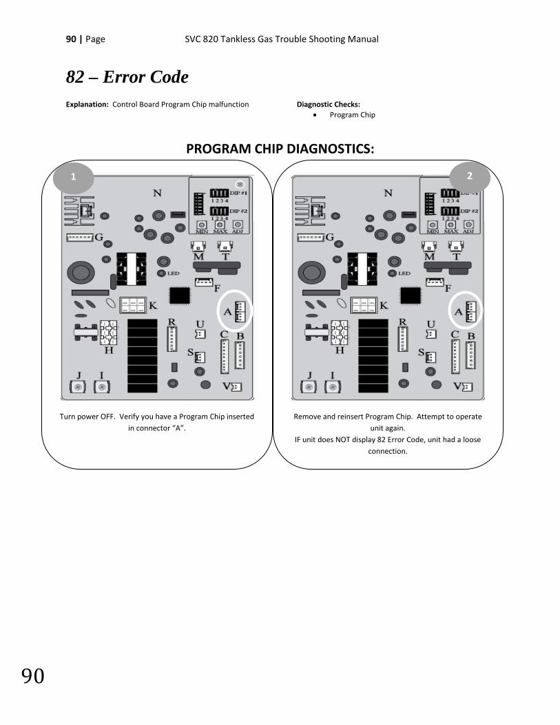
90 | Page SVC 820 Tankless Gas Trouble Shooting Manual
90
82 – Error Code Explanation: Control Board Program Chip malfunction
Diagnostic Checks: • Program Chip
PROGRAM CHIP DIAGNOSTICS:
Turn power OFF. Verify you have a Program Chip inserted in connector “A”.
1
Remove and reinsert Program Chip. Attempt to operate unit again.
IF unit does NOT display 82 Error Code, unit had a loose connection.
2
SVC 820-Tankless Gas Trouble Shooting Manual Page | 91
91
90 – Error Code Explanation: The unit detected blockage in the venting during pre-purge cycle. This Error Code will occur BEFORE unit goes to ignition. Possible Causes:
• VENTING
VENTING:
**REFER TO USE & CARE MANUAL** Visually inspect venting for possible blockage and/or recirculation of exhaust.
1. Approved Venting Materials 2. Approved Vent Terminations 3. Vent Lengths 4. Location Of Vent Termination (Recirculation of exhaust) 5. Blocked Venting 6. Venting Not Sealed Properly
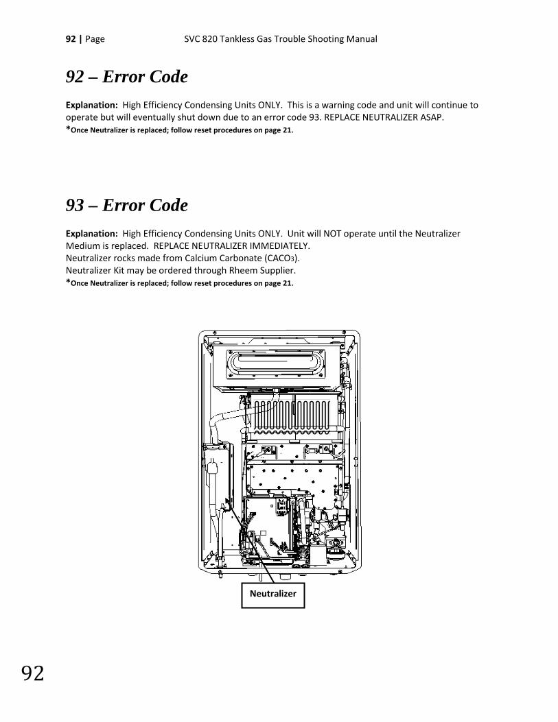
92 | Page SVC 820 Tankless Gas Trouble Shooting Manual
92
92 – Error Code Explanation: High Efficiency Condensing Units ONLY. This is a warning code and unit will continue to operate but will eventually shut down due to an error code 93. REPLACE NEUTRALIZER ASAP. *Once Neutralizer is replaced; follow reset procedures on page 21.
93 – Error Code Explanation: High Efficiency Condensing Units ONLY. Unit will NOT operate until the Neutralizer Medium is replaced. REPLACE NEUTRALIZER IMMEDIATELY. Neutralizer rocks made from Calcium Carbonate (CACO3). Neutralizer Kit may be ordered through Rheem Supplier. *Once Neutralizer is replaced; follow reset procedures on page 21.
Neutralizer
SVC 820-Tankless Gas Trouble Shooting Manual Page | 93
93
99 – Error Code Explanation: The unit detected blockage in the venting during post-purge cycle. Blockage was detected when the demand for hot water terminated and burner was OFF. This error code will only occur at time of shut down. *Unit must be reset by performing reset procedure on page 21. Possible Causes:
• Venting
VENTING:
**REFER TO USE & CARE MANUAL**
Visually inspect venting for possible blockage and/or recirculation of exhaust. 1. Approved Venting Materials 2. Approved Vent Terminations 3. Vent Lengths 4. Location Of Vent Termination (Recirculation of exhaust) 5. Blocked Venting 6. Venting Not Sealed Properly

94 | Page SVC 820 Tankless Gas Trouble Shooting Manual
94
NOTES:
________________________________________________________________________________________________________________________________________________________________________________________________________________________________________________________________________________________________________________________________________________________________________________________________________________________________________________________________________________________________________________________________________________________________________________________________________________________________________________________________________________________________________________________________________________________________________________________________________________________________________________________________________________________________________________________________________________________
SVC 820-Tankless Gas Trouble Shooting Manual Page | 95
95
NOTES:
________________________________________________________________________________________________________________________________________________________________________________________________________________________________________________________________________________________________________________________________________________________________________________________________________________________________________________________________________________________________________________________________________________________________________________________________________________________________________________________________________________________________________________________________________________________________________________________________________________________________________________________________________________________________________________________________________________________
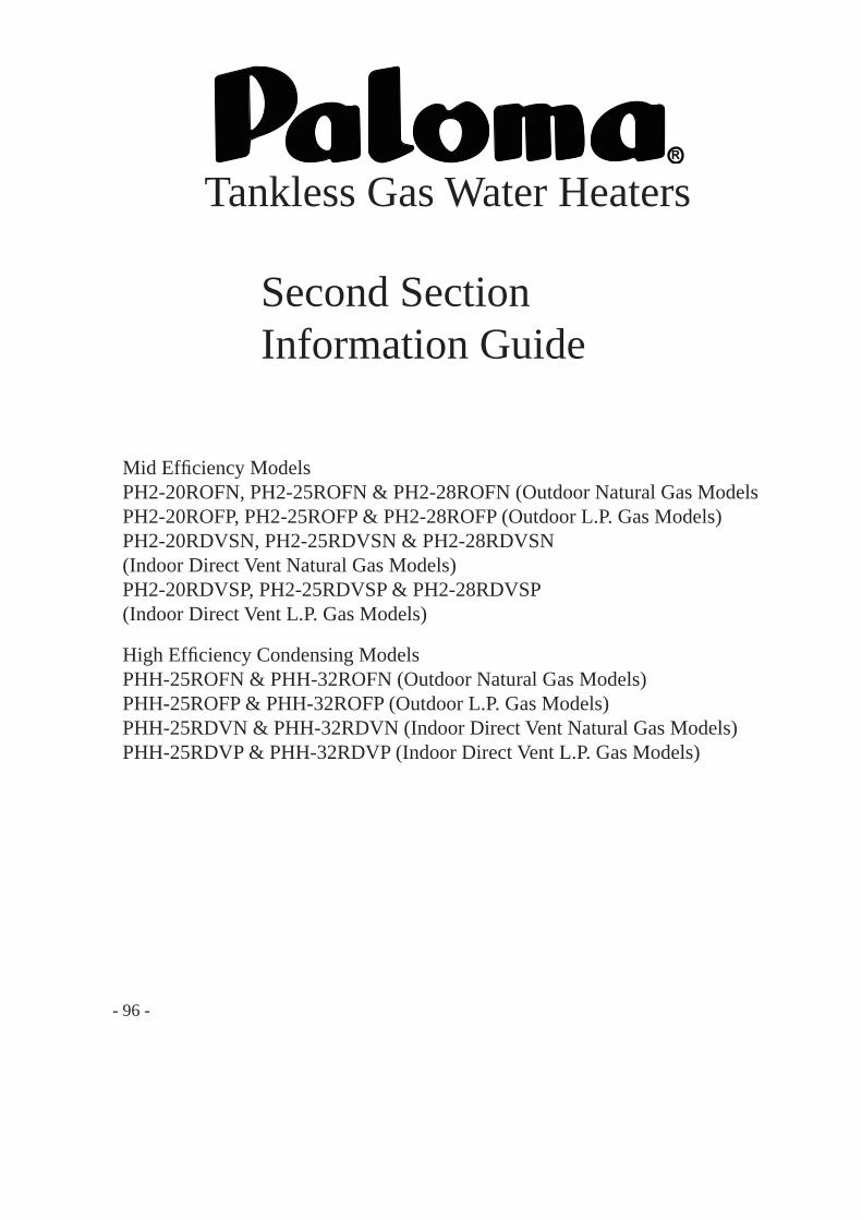
R
Tankless Gas Water Heaters
High Effi ciency Condensing ModelsPHH-25ROFN & PHH-32ROFN (Outdoor Natural Gas Models)PHH-25ROFP & PHH-32ROFP (Outdoor L.P. Gas Models)PHH-25RDVN & PHH-32RDVN (Indoor Direct Vent Natural Gas Models)PHH-25RDVP & PHH-32RDVP (Indoor Direct Vent L.P. Gas Models)
Mid Effi ciency ModelsPH2-20ROFN, PH2-25ROFN & PH2-28ROFN (Outdoor Natural Gas ModelsPH2-20ROFP, PH2-25ROFP & PH2-28ROFP (Outdoor L.P. Gas Models)PH2-20RDVSN, PH2-25RDVSN & PH2-28RDVSN (Indoor Direct Vent Natural Gas Models)PH2-20RDVSP, PH2-25RDVSP & PH2-28RDVSP(Indoor Direct Vent L.P. Gas Models)
Second SectionInformation Guide
- 96 -
- Do not store or use gasoline or other flammable vapors and liquids in the vicinity of this or any other appliance. To do so may result in an explosion or fire.
- WHAT TO DO IF YOU SMELL GAS * Do not try to light any appliance. * Do not touch any electrical switch; do not use any phone in your building. * Immediately call your gas supplier from a neighbor's phone. Follow the gas supplier's instructions. * If you cannot reach your gas supplier, call the fire department. * Do not return to your home until authorized by the gas supplier or fire department.
- Installation and service must be performed by a qualified installer, service agency or the gas supplier.
WARNING: If the information in these instructions is not followed exactly, a fire or explosion may result causing property damage, personal injury or death.
WARNING: Improper installation, adjustment, alternation, service or maintenance can cause property damage, personal injury, or death. For assistance or additional information, consult with a qualifi ed distributor.
WARNING: The content on this manual is intended for use by qualifi ed service personnel ONLY.
Table of Contents for Second Section
- 97 -
PageSpecifi cations .................................................................. 98 ~ 99External Dimensions ...................................................... 100 ~ 101Schematic Construction ................................................. 102 ~ 105Operational Principle ..................................................... 106 ~ 111Capacity ......................................................................... 112 ~ 120Wiring Diagram ............................................................. 121 ~ 122Thermistor Resistance Chart .......................................... 123Adjustment ..................................................................... 124 ~ 132DUOnex Cable ............................................................... 133 ~ 136MIC-185 ......................................................................... 137 ~ 146MIC-6 ............................................................................. 147 ~ 154Commercial Conversion ................................................ 155 ~ 157Schematic Disassembly and Parts List .......................... 158 ~ 171
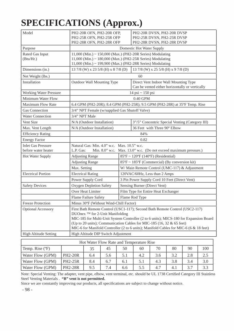
SPECIFICATIONS (Approx.)Model PH2-20R OFN, PH2-20R OFP,
PH2-25R OFN, PH2-25R OFPPH2-28R OFN, PH2-28R OFP
PH2-20R DVSN, PH2-20R DVSPPH2-25R DVSN, PH2-25R DVSPPH2-28R DVSN, PH2-28R DVSP
Purpose Domestic Hot Water SupplyRated Gas Input(Btu/Hr.)
11,000 (Min.) ~ 150,000 (Max.) (PH2-20R Series) Modulating11,000 (Min.) ~ 180,000 (Max.) (PH2-25R Series) Modulating 11,000 (Min.) ~ 199,900 (Max.) (PH2-28R Series) Modulating
Dimensions (in.) 13 7/8 (W) x 23 5/8 (H) x 8 7/8 (D) 13 7/8 (W) x 25 5/8 (H) x 9 7/8 (D)
Net Weight (lbs.) 60Installation Outdoor Wall Mounting Type Direct Vent Indoor Wall Mounting Type
Can be vented either horizontally or verticallyWorking Water Pressure 14 psi ~ 150 psiMinimum Water Flow 0.40 GPMMaximum Flow Rate 6.4 GPM (PH2-20R); 8.4 GPM (PH2-25R); 9.5 GPM (PH2-28R) at 35ºF Temp. RiseGas Connection 3/4” NPT Female (w/supplied Gas Shutoff Valve)Water Connection 3/4” NPT MaleVent Size N/A (Outdoor Installation) 3”/5” Concentric Special Venting (Category III)Max. Vent Length N/A (Outdoor Installation) 36 Feet with Three 90º ElbowEffi ciency Rating 84% Energy Factor 0.82Inlet Gas Pressurebefore water heater
Natural Gas: Min. 4.0” w.c. Max. 10.5” w.c.L.P. Gas: Min. 8.0” w.c. Max. 13.0” w.c. (Do not exceed maximum pressure.)
Hot Water Supply Adjusting Range 85ºF ~ 120ºF (140ºF) (Residential)Adjusting Range 85ºF ~ 185ºF (Commercial) (By conversion kit)Max. Setting W/ Main Remote Control (UMC-117) & Adjustment
Electrical Portion Electrical Rating 120VAC/60Hz, Less than 2 AmpsPower Supply Cord 3 Pin Power Supply Cord 10 Feet (Direct Vent)
Safety Devices Oxygen Depletion Safety Sensing Burner (Direct Vent)Over Heat Limiter Film Type for Entire Heat ExchangerFlame Failure Safety Flame Rod Type
Freeze Protection Minus 30ºF (Without Wind-Chill Factor)Optional Accessory First Bath Remote Control (USC1-117); Second Bath Remote Control (USC2-117)
DUOnex ™ for 2-Unit ManifoldingMIC-185 for Multi-Unit System Controller (2 to 6 units); MICS-180 for Expansion Board(Up to 20 units); Communication Cables for MIC-185 (16, 32 & 65 feet)MIC-6 for Manifold Controller (2 to 6 units); Manifold Cables for MIC-6 (6 & 18 feet)
High Altitude Setting High Altitude DIP Switch Adjustment
Hot Water Flow Rate and Temperature RiseTemp. Rise (ºF) 35 45 50 60 70 80 90 100Water Flow (GPM) PH2-20R 6.4 5.6 5.1 4.2 3.6 3.2 2.8 2.5Water Flow (GPM) PH2-25R 8.4 6.7 6.1 5.1 4.3 3.8 3.4 3.0Water Flow (GPM) PH2-28R 9.5 7.4 6.6 5.5 4.7 4.1 3.7 3.3
- 98 -
Note: Special Venting: The adapter, vent pipe, elbow, vent terminal, etc. should be UL 1738 Certifi ed Category III Stainless Steel Venting Materials . “B” vent is not permitted.Since we are constantly improving our products, all specifi cations are subject to change without notice.
SPECIFICATIONS (Approx.)Model PHH-25ROFN, PHH-25ROFP
PHH-32ROFN, PHH-32ROFPPHH-25RDVN, PHH-25RDVPPHH-32RDVN, PHH-32RDVP
Purpose Domestic Hot Water SupplyRated Gas Input(Btu/Hr.)
11,000 (Min.) ~ 157,000 (Max.) (PHH-25R Series) Modulating 11,000 (Min.) ~ 199,900 (Max.) (PHH-32R Series) Modulating
Dimensions (in.) 18 1/2 (W) x 27 5/8 (H) x 9 3/4 (D) 18 1/2 (W) x 30 3/8 (H) x 9 3/4 (D)
Net Weight (lbs.) 76Installation Outdoor Wall Mounting Type Direct Vent Indoor Wall Mounting Type
Can be vented either horizontally or verticallyWorking Water Pressure 14 psi ~ 150 psiMinimum Water Flow 0.40 GPMMaximum Flow Rate 8.5 GPM (PHH-25R); 9.5 GPM (PHH-32R) at 35ºF Temp. RiseGas Connection 3/4” NPT Female (w/supplied Gas Shutoff Valve)Water Connection 3/4” NPT MaleVent Size N/A (Outdoor Installation) 2” or 3” PVC or CPVCMax. Vent Length N/A (Outdoor Installation) 35 Feet with Three 90º Elbow (3” PVC)
5 Feet with One 90º Elbow (2” PVC)Effi ciency Rating 93% (PHH-25ROF, PHH-32ROF, PHH-32RDV); 94% (PHH-25RDV) Energy Factor 0.93 (PHH-25ROF); 0.94 (PHH-25RDV, PHH-32ROF, PHH-32RDV)Inlet Gas Pressurebefore water heater
Natural Gas: Min. 4.0” w.c. Max. 10.5” w.c.L.P. Gas: Min. 8.0” w.c. Max. 13.0” w.c. (Do not exceed maximum pressure.)
Hot Water Supply Adjusting Range 85ºF ~ 120ºF (140ºF) (Residential)Adjusting Range 85ºF ~ 185ºF (Commercial) (By conversion kit)Max. Setting W/ Main Remote Control (UMC-117) & Adjustment
Electrical Portion Electrical Rating 120VAC/60Hz, Less than 2 AmpsPower Supply Cord 3 Pin Power Supply Cord 10 Feet (Direct Vent)
Safety Devices Oxygen Depletion Safety Flame Rod (Direct Vent)Over Heat Limiter Film Type for Entire Heat ExchangerFlame Failure Safety Flame Rod Type
Freeze Protection Minus 30ºF (Without Wind-Chill Factor)Optional Accessory First Bath Remote Control (USC1-117); Second Bath Remote Control (USC2-117)
DUOnex ™ for 2-Unit ManifoldingMIC-185 for Multi-Unit System Controller (2 to 6 units); MICS-180 for Expansion Board(Up to 20 units); Communication Cables for MIC-185 (16, 32 & 65 feet)MIC-6 for Manifold Controller (2 to 6 units); Manifold Cables for MIC-6 (6 & 18 feet)
High Altitude Setting High Altitude DIP Switch Adjustment
Hot Water Flow Rate and Temperature RiseTemp. Rise (ºF) 35 45 50 60 70 80 90 100Water Flow (GPM) PHH-25R 8.5 6.6 5.9 4.9 4.2 3.7 3.3 3.0Water Flow (GPM) PHH-32R 9.5 8.4 7.6 6.3 5.4 4.7 4.2 3.8
- 99 -
Note: Venting: Schedule 40 (PVC), Schedule 40 (CPVC) or Category III Stainless Steel . “B” vent is not permitted.Since we are constantly improving our products, all specifi cations are subject to change without notice.
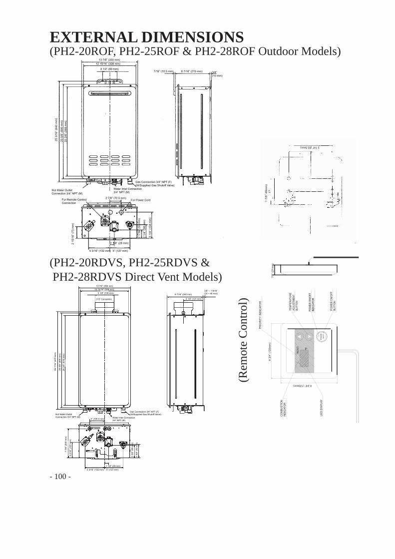
EXTERNAL DIMENSIONS
(Rem
ote
Con
trol)
COM
BUST
ION
IND
ICAT
OR
POW
ER O
N/O
FFIN
DIC
ATO
R
POW
ER O
N/O
FFBU
TTO
N
PRIO
RIT
Y IN
DIC
ATO
R
TEM
PERA
TURE
ADJU
STM
ENT
BUTT
ON
LED
DIS
PLAY
POW
ERO
N/O
FF
PRIO
RITY
°F
7/8”
(21m
m)
4 3/
4” (1
20m
m)
4 3/4” (120mm)
1 7/
8” 4
6mm
)
3 1/4” (83.5mm)
13 7/8” (350 mm) 12 15/16” (328 mm)
3 1/2” (90 mm)
25 3
/16”
(640
mm
)
23 5
/8” (
600
mm
) 22
3/8
” (56
8 m
m)
2 7/8” (72.5 mm)
2 15
/16”
(73
mm
)
5 3/16” (132 mm)
1 1/8” (28 mm)
5” (127 mm)
2 1/
16” (
53 m
m)
2 1/
4” (5
8 m
m)
5 1/
4” (1
34 m
m)
7/16” (10.5 mm) 8 7/16” (215 mm) 3/8” (10 mm)
Hot Water OutletConnection 3/4” NPT (M)
Water Inlet Connection 3/4” NPT (M)
Gas Connection 3/4” NPT (F)(W/Supplied Gas Shutoff Valve)
For Power CordFor Remote ControlConnection
(PH2-20ROF, PH2-25ROF & PH2-28ROF Outdoor Models)
13 7/8” (350 mm) 12 15/16” (328 mm)
5 1/8” (130 mm)
3”/5” Concentric
9 7/16” (240 mm)
5 1/8” (131 mm)
3/8” ~ 1 9/16” (10 ~ 40 mm)
Hot Water OutletConnection 3/4” NPT (M) Water Inlet Connection
3/4” NPT (M)
Gas Connection 3/4” NPT (F)(W/Supplied Gas Shutoff Valve)
3” (100.5 mm)
5 3/16” (132 mm) 5” (127 mm)1 1/8” (28 mm)
7 7/
8” (2
00 m
m)
4 3/
16” (
107
mm
)
3 3/
8” (8
6 m
m)
3 5/
8” (9
2 m
m)
26 7
/16”
(672
mm
)
25 5
/8” (
650
mm
)
24 3
/8” (
618
mm
)
(PH2-20RDVS, PH2-25RDVS & PH2-28RDVS Direct Vent Models)
- 100 -
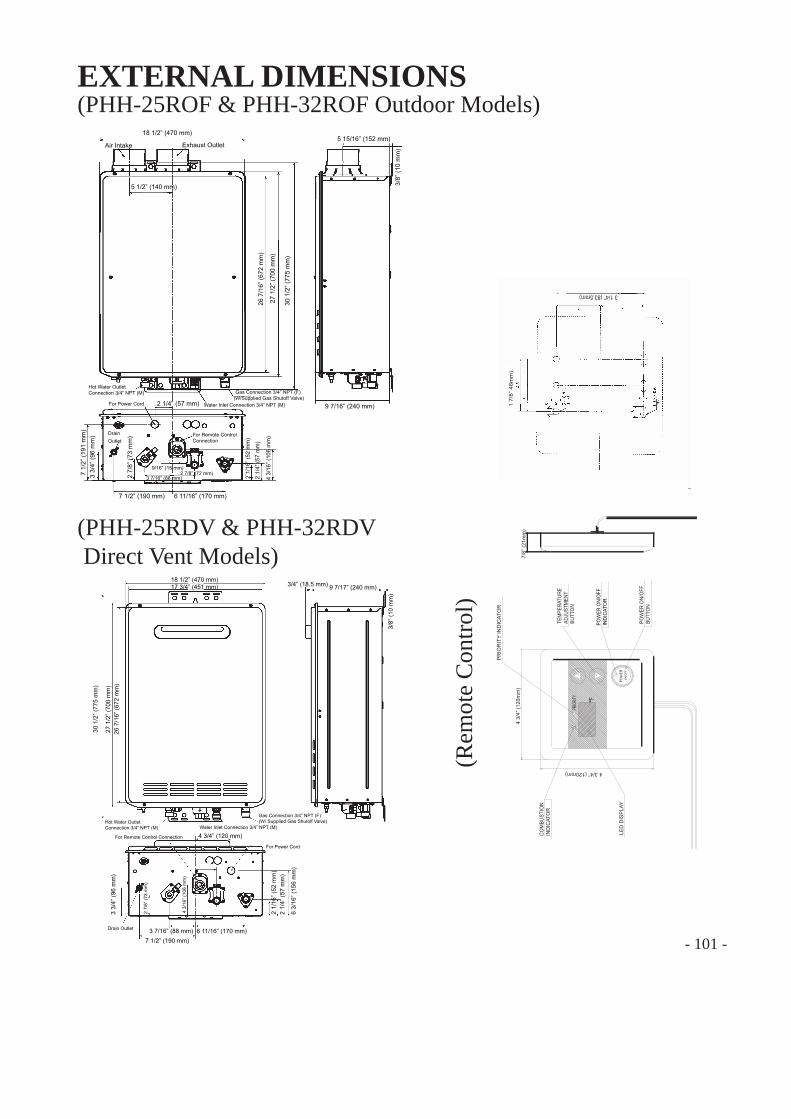
EXTERNAL DIMENSIONS
(Rem
ote
Con
trol)
COM
BUST
ION
IND
ICAT
OR
POW
ER O
N/O
FFIN
DIC
ATO
R
POW
ER O
N/O
FFBU
TTO
N
PRIO
RIT
Y IN
DIC
ATO
R
TEM
PERA
TURE
ADJU
STM
ENT
BUTT
ON
LED
DIS
PLAY
POW
ERO
N/O
FF
PRIO
RITY
°F
7/8”
(21m
m)
4 3/
4” (1
20m
m)
4 3/4” (120mm)
1 7/
8” 4
6mm
)
3 1/4” (83.5mm)
(PHH-25ROF & PHH-32ROF Outdoor Models)
(PHH-25RDV & PHH-32RDV Direct Vent Models)
- 101 -
18 1/2” (470 mm)
Air Intake Exhaust Outlet
5 1/2” (140 mm)
5 15/16” (152 mm)
3/8
” (10
mm
)
30 1
/2” (
775
mm
)
27 1
/2” (
700
mm
)
26 7
/16”
(672
mm
)
9 7/16” (240 mm)
Hot Water OutletConnection 3/4” NPT (M) Gas Connection 3/4” NPT (F)
(W/Supplied Gas Shutoff Valve)Water Inlet Connection 3/4” NPT (M) For Power Cord
For Remote ControlConnection
2 1/4” (57 mm)
Drain Outlet
7 1/
2” (1
91 m
m)
3 3/
4” (9
6 m
m)
6 11/16” (170 mm)
2 7/
8” (7
3 m
m)
3 7/16” (88 mm) 2 7/8” (72 mm)
9/16” (15 mm)
7 1/2” (190 mm)
2 1/
4” (5
7 m
m)
4 3/
16” (
106
mm
)
2 1/
16” (
52 m
m)
18 1/2” (470 mm) 17 3/4” (451 mm) 9 7/17” (240 mm)
3/8”
(10
mm
)
3/4” (18.5 mm)
26 7
/16”
(672
mm
) 27
1/2
” (70
0 m
m)
30 1
/2” (
775
mm
)
Hot Water OutletConnection 3/4” NPT (M) Water Inlet Connection 3/4” NPT (M)
Gas Connection 3/4” NPT (F)(W/ Supplied Gas Shutoff Valve)
4 3/4” (120 mm)
For Power Cord For Remote Control Connection
3 3/
4” (9
6 m
m)
Drain Outlet 3 7/16” (88 mm) 6 11/16” (170 mm)
2 7/
8” (7
3 m
m)
4 3/
16” (
106
mm
)
6 3/
16” (
156
mm
)
2 1/
4” (5
7 m
m)
2 1/
16” (
52 m
m)
7 1/2” (190 mm)
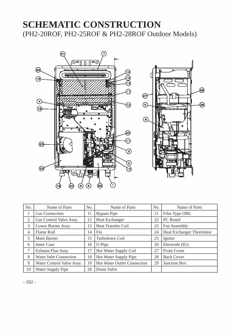
- 102 -
SCHEMATIC CONSTRUCTION(PH2-20ROF, PH2-25ROF & PH2-28ROF Outdoor Models)
No. Name of Parts No. Name of Parts No. Name of Parts1 Gas Connection 11 Bypass Pipe 21 Film Type OHL2 Gas Control Valve Assy. 12 Heat Exchanger 22 PC Board3 Lower Burner Assy. 13 Heat Transfer Coil 23 Fan Assembly4 Flame Rod 14 Fin 24 Heat Exchanger Thermistor5 Main Burner 15 Turbulence Coil 25 Igniter6 Inner Case 16 U-Pipe 26 Electrode (IG)7 Exhaust Flue Assy. 17 Hot Water Supply Coil 27 Front Cover8 Water Inlet Connection 18 Hot Water Supply Pipe 28 Back Cover9 Water Control Valve Assy. 19 Hot Water Outlet Connection 29 Junction Box10 Water Supply Pipe 20 Drain Valve
- 103 -
SCHEMATIC CONSTRUCTION
No. Name of Parts No. Name of Parts No. Name of Parts1 Gas Connection 11 Bypass Pipe 21 Film Type OHL2 Gas Control Valve Assy. 12 Heat Exchanger 22 Heat Exchanger Thermistor3 Lower Burner Assy. 13 Heat Transfer Coil 23 PC Board4 Flame Rod 14 Fin 24 Fan Assembly5 Main Burner 15 Turbulence Coil 25 Electrode (IG)6 Inner Case 16 U-Pipe 26 Igniter7 Exhaust Flue Assy. 17 Hot Water Supply Coil 27 Back Cover8 Water Inlet Connection 18 Hot Water Supply Pipe 28 Front Cover9 Water Control Valve Assy. 19 Hot Water Outlet Connection10 Water Supply Pipe 20 Drain Valve
(PH2-20RDVS, PH2-25RDVS & PH2-28RDVS Direct Vent Models)
- 104 -
SCHEMATIC CONSTRUCTION(PHH-25ROF & PHH-32ROF Outdoor Models)
No. Name of Parts No. Name of Parts No. Name of Parts1 Front Cover 11 Gas Control Valve Assy. 21 Water Control Valve Assy.2 Back Cover 12 Fan Assembly 22 Water Supply Pipe3 Heat Exchanger 13 Film Type OHL 23 Bypass Pipe4 Fin 14 Igniter 24 Turbulence Coil5 Heat Transfer Coil 15 PC Board 25 Hot Water Supply Coil6 Inner Case 16 Electrode (FL 1) 26 Hot Water Supply Pipe7 Exhaust Flue Assy. 17 Electrode (IG) 27 Hot Water Outlet Connection8 Second Heat Exchanger
Top Plate Assy.18 Gas Connection 28 Drain Valve
9 Second Heat Exchanger 19 Lower Burner Assy.10 Main Burner 20 Water Inlet Connection
- 105 -
SCHEMATIC CONSTRUCTION
No. Name of Parts No. Name of Parts No. Name of Parts1 Front Cover 11 Gas Control Valve Assy. 21 Water Control Valve Assy.2 Back Cover 12 Fan Assembly 22 Water Supply Pipe3 Heat Exchanger 13 Film Type OHL 23 Bypass Pipe4 Fin 14 Igniter 24 Turbulence Coil5 Heat Transfer Coil 15 Electrode (FL 2) 25 Hot Water Supply Coil6 Inner Case 16 Electrode (FL 1) 26 Hot Water Supply Pipe7 Exhaust Flue Assy. 17 Electrode (IG) 27 Hot Water Outlet Connection8 Second Heat Exchanger
Top Plate Assy.18 Gas Connection 28 Drain Valve
9 Second Heat Exchanger 19 Lower Burner Assy. 29 PC Board10 Main Burner 20 Water Inlet Connection
(PHH-25RDV & PHH-32RDV Direct Vent Models)

- 106 -
OPERATIONAL PRINCIPLE
No. Name of Parts No. Name of Parts No. Name of Parts1 Hot Water Tap 11 Solenoid Valve 2 21 Film Type OHL2 Water Flow Servo 12 Solenoid Valve 3 22 Fan3 Water Flow Sensor 13 Solenoid Valve 4 23 Fan Motor4 Water Inlet Thermistor 14 Proportional Gas Control Valve 24 Drain Valve5 Heat Exchanger Thermistor 15 Orifi ce 25 Remote Control6 Hot Water Outlet Thermistor 16 Igniter 26 Freeze Protection Heater7 PC Board 17 Electrode 27 Bypass Solenoid Valve8 Water Filter 18 Flame Rod 28 Exhaust Outlet9 Gas Inlet Solenoid Valve 19 Main Burner10 Solenoid Valve 1 20 Heat Exchanger
Hot Water Outlet
Water Inlet
Gas Inlet
Exhaust Gas
(PH2-20ROF, PH2-25ROF & PH2-28ROF Outdoor Models)
- 107 -
OPERATIONAL PRINCIPLE
Air Intake
ExhaustOutlet
Hot Water Outlet
Water Inlet
Gas Inlet
(PH2-20RDVS, PH2-25RDVS & PH2-28RDVS Direct Vent Models)
No. Name of Parts No. Name of Parts No. Name of Parts1 Hot Water Tap 11 Solenoid Valve 2 21 Film Type OHL2 Water Flow Servo 12 Solenoid Valve 3 22 Fan3 Water Flow Sensor 13 Solenoid Valve 4 23 Fan Motor4 Water Inlet Thermistor 14 Proportional Gas Control Valve 24 Drain Valve5 Heat Exchanger Thermistor 15 Orifi ce 25 Remote Control6 Hot Water Outlet Thermistor 16 Igniter 26 Freeze Protection Heater7 PC Board 17 Electrode 1 27 Bypass Solenoid Valve8 Water Filter 18 Flame Rod 28 Exhaust Outlet9 Gas Inlet Solenoid Valve 19 Main Burner 29 Flame Rod 2 (ODS)10 Solenoid Valve 1 20 Heat Exchanger
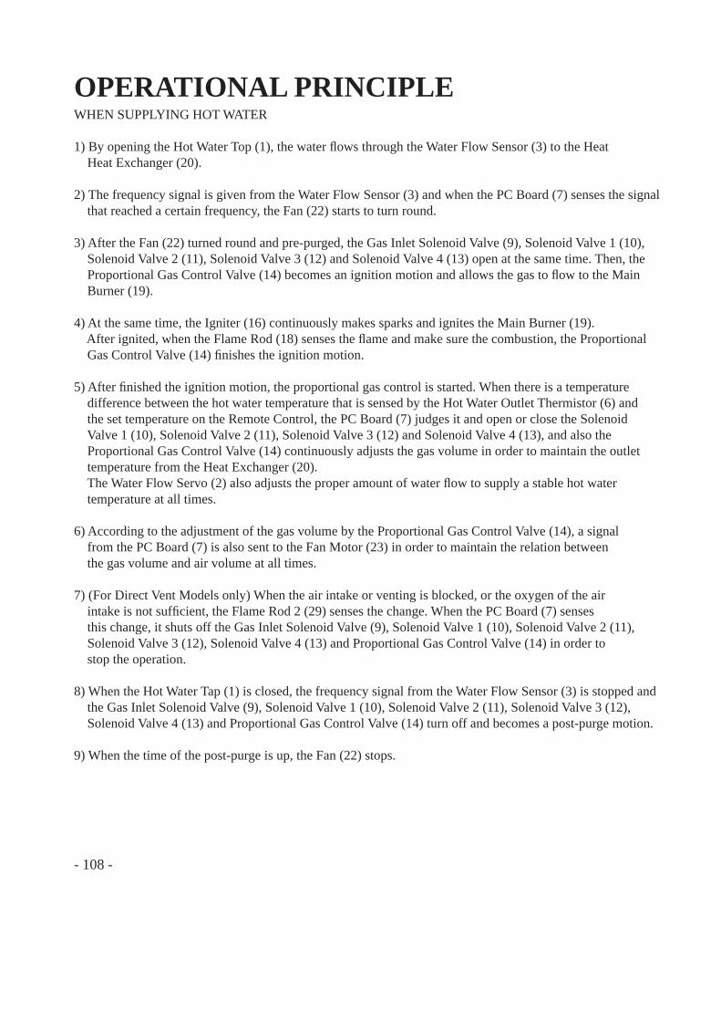
- 108 -
OPERATIONAL PRINCIPLEWHEN SUPPLYING HOT WATER
1) By opening the Hot Water Top (1), the water fl ows through the Water Flow Sensor (3) to the Heat Heat Exchanger (20).
2) The frequency signal is given from the Water Flow Sensor (3) and when the PC Board (7) senses the signal that reached a certain frequency, the Fan (22) starts to turn round.
3) After the Fan (22) turned round and pre-purged, the Gas Inlet Solenoid Valve (9), Solenoid Valve 1 (10), Solenoid Valve 2 (11), Solenoid Valve 3 (12) and Solenoid Valve 4 (13) open at the same time. Then, the Proportional Gas Control Valve (14) becomes an ignition motion and allows the gas to fl ow to the Main Burner (19).
4) At the same time, the Igniter (16) continuously makes sparks and ignites the Main Burner (19). After ignited, when the Flame Rod (18) senses the fl ame and make sure the combustion, the Proportional Gas Control Valve (14) fi nishes the ignition motion.
5) After fi nished the ignition motion, the proportional gas control is started. When there is a temperature difference between the hot water temperature that is sensed by the Hot Water Outlet Thermistor (6) and the set temperature on the Remote Control, the PC Board (7) judges it and open or close the Solenoid Valve 1 (10), Solenoid Valve 2 (11), Solenoid Valve 3 (12) and Solenoid Valve 4 (13), and also the Proportional Gas Control Valve (14) continuously adjusts the gas volume in order to maintain the outlet temperature from the Heat Exchanger (20). The Water Flow Servo (2) also adjusts the proper amount of water fl ow to supply a stable hot water temperature at all times.
6) According to the adjustment of the gas volume by the Proportional Gas Control Valve (14), a signal from the PC Board (7) is also sent to the Fan Motor (23) in order to maintain the relation between the gas volume and air volume at all times.
7) (For Direct Vent Models only) When the air intake or venting is blocked, or the oxygen of the air intake is not suffi cient, the Flame Rod 2 (29) senses the change. When the PC Board (7) senses this change, it shuts off the Gas Inlet Solenoid Valve (9), Solenoid Valve 1 (10), Solenoid Valve 2 (11), Solenoid Valve 3 (12), Solenoid Valve 4 (13) and Proportional Gas Control Valve (14) in order to stop the operation.
8) When the Hot Water Tap (1) is closed, the frequency signal from the Water Flow Sensor (3) is stopped and the Gas Inlet Solenoid Valve (9), Solenoid Valve 1 (10), Solenoid Valve 2 (11), Solenoid Valve 3 (12), Solenoid Valve 4 (13) and Proportional Gas Control Valve (14) turn off and becomes a post-purge motion.
9) When the time of the post-purge is up, the Fan (22) stops.
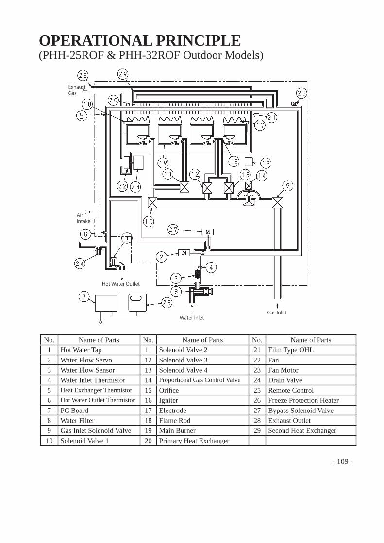
- 109 -
OPERATIONAL PRINCIPLE
No. Name of Parts No. Name of Parts No. Name of Parts1 Hot Water Tap 11 Solenoid Valve 2 21 Film Type OHL2 Water Flow Servo 12 Solenoid Valve 3 22 Fan3 Water Flow Sensor 13 Solenoid Valve 4 23 Fan Motor4 Water Inlet Thermistor 14 Proportional Gas Control Valve 24 Drain Valve5 Heat Exchanger Thermistor 15 Orifi ce 25 Remote Control6 Hot Water Outlet Thermistor 16 Igniter 26 Freeze Protection Heater7 PC Board 17 Electrode 27 Bypass Solenoid Valve8 Water Filter 18 Flame Rod 28 Exhaust Outlet9 Gas Inlet Solenoid Valve 19 Main Burner 29 Second Heat Exchanger10 Solenoid Valve 1 20 Primary Heat Exchanger
(PHH-25ROF & PHH-32ROF Outdoor Models)
Exhaust Gas
Air Intake
Hot Water Outlet
Water InletGas Inlet
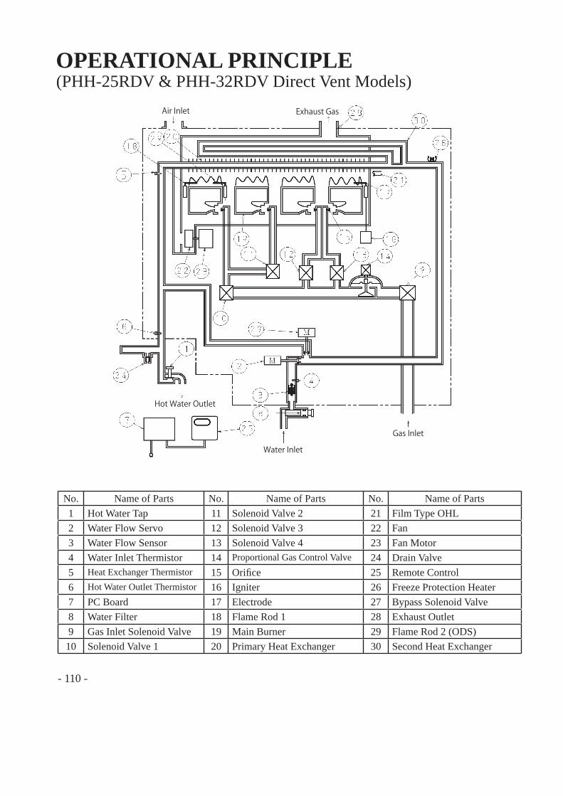
- 110 -
OPERATIONAL PRINCIPLE(PHH-25RDV & PHH-32RDV Direct Vent Models)
No. Name of Parts No. Name of Parts No. Name of Parts1 Hot Water Tap 11 Solenoid Valve 2 21 Film Type OHL2 Water Flow Servo 12 Solenoid Valve 3 22 Fan3 Water Flow Sensor 13 Solenoid Valve 4 23 Fan Motor4 Water Inlet Thermistor 14 Proportional Gas Control Valve 24 Drain Valve5 Heat Exchanger Thermistor 15 Orifi ce 25 Remote Control6 Hot Water Outlet Thermistor 16 Igniter 26 Freeze Protection Heater7 PC Board 17 Electrode 27 Bypass Solenoid Valve8 Water Filter 18 Flame Rod 1 28 Exhaust Outlet9 Gas Inlet Solenoid Valve 19 Main Burner 29 Flame Rod 2 (ODS)10 Solenoid Valve 1 20 Primary Heat Exchanger 30 Second Heat Exchanger
Air Inlet Exhaust Gas
Hot Water Outlet
Water Inlet
Gas Inlet
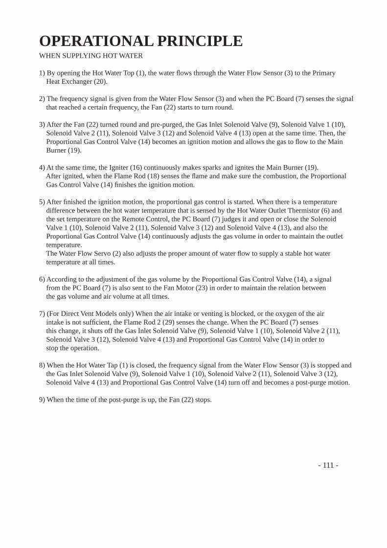
- 111 -
OPERATIONAL PRINCIPLEWHEN SUPPLYING HOT WATER
1) By opening the Hot Water Top (1), the water fl ows through the Water Flow Sensor (3) to the Primary Heat Exchanger (20).
2) The frequency signal is given from the Water Flow Sensor (3) and when the PC Board (7) senses the signal that reached a certain frequency, the Fan (22) starts to turn round.
3) After the Fan (22) turned round and pre-purged, the Gas Inlet Solenoid Valve (9), Solenoid Valve 1 (10), Solenoid Valve 2 (11), Solenoid Valve 3 (12) and Solenoid Valve 4 (13) open at the same time. Then, the Proportional Gas Control Valve (14) becomes an ignition motion and allows the gas to fl ow to the Main Burner (19).
4) At the same time, the Igniter (16) continuously makes sparks and ignites the Main Burner (19). After ignited, when the Flame Rod (18) senses the fl ame and make sure the combustion, the Proportional Gas Control Valve (14) fi nishes the ignition motion.
5) After fi nished the ignition motion, the proportional gas control is started. When there is a temperature difference between the hot water temperature that is sensed by the Hot Water Outlet Thermistor (6) and the set temperature on the Remote Control, the PC Board (7) judges it and open or close the Solenoid Valve 1 (10), Solenoid Valve 2 (11), Solenoid Valve 3 (12) and Solenoid Valve 4 (13), and also the Proportional Gas Control Valve (14) continuously adjusts the gas volume in order to maintain the outlet temperature. The Water Flow Servo (2) also adjusts the proper amount of water fl ow to supply a stable hot water temperature at all times.
6) According to the adjustment of the gas volume by the Proportional Gas Control Valve (14), a signal from the PC Board (7) is also sent to the Fan Motor (23) in order to maintain the relation between the gas volume and air volume at all times.
7) (For Direct Vent Models only) When the air intake or venting is blocked, or the oxygen of the air intake is not suffi cient, the Flame Rod 2 (29) senses the change. When the PC Board (7) senses this change, it shuts off the Gas Inlet Solenoid Valve (9), Solenoid Valve 1 (10), Solenoid Valve 2 (11), Solenoid Valve 3 (12), Solenoid Valve 4 (13) and Proportional Gas Control Valve (14) in order to stop the operation.
8) When the Hot Water Tap (1) is closed, the frequency signal from the Water Flow Sensor (3) is stopped and the Gas Inlet Solenoid Valve (9), Solenoid Valve 1 (10), Solenoid Valve 2 (11), Solenoid Valve 3 (12), Solenoid Valve 4 (13) and Proportional Gas Control Valve (14) turn off and becomes a post-purge motion.
9) When the time of the post-purge is up, the Fan (22) stops.
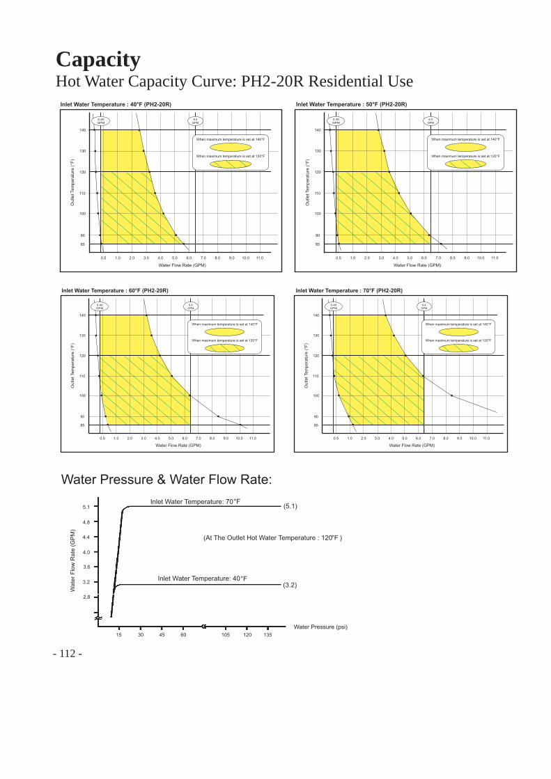
- 112 -
CapacityHot Water Capacity Curve: PH2-20R Residential Use
0.5 1.0 2.0 3.0 4.0 5.0 6.0 7.0 8.0 9.0 10.0 11.0
85
100
120
130
140
Inlet Water Temperature : 40°F (PH2-20R)
Water Flow Rate (GPM)
Out
let T
empe
ratu
re (°
F)
6.4 GPM
When maximum temperature is set at 140°F
When maximum temperature is set at 120°F
90
110
0.40 GPM
0.5 1.0 2.0 3.0 4.0 5.0 6.0 7.0 8.0 9.0 10.0 11.0
85
100
120
130
140
Inlet Water Temperature : 50°F (PH2-20R)
Water Flow Rate (GPM)
Out
let T
empe
ratu
re (°
F)
90
110
0.40 GPM
6.4 GPM
When maximum temperature is set at 140°F
When maximum temperature is set at 120°F
0.5 1.0 2.0 3.0 4.0 5.0 6.0 7.0 8.0 9.0 10.0 11.0
85
100
120
130
140
Inlet Water Temperature : 60°F (PH2-20R)
Water Flow Rate (GPM)
Out
let T
empe
ratu
re (°
F)
90
110
0.40 GPM
When maximum temperature is set at 140°F
When maximum temperature is set at 120°F
6.4 GPM
0.5 1.0 2.0 3.0 4.0 5.0 6.0 7.0 8.0 9.0 10.0 11.0
85
100
120
130
140
Inlet Water Temperature : 70°F (PH2-20R)
Water Flow Rate (GPM)
Out
let T
empe
ratu
re (°
F)
90
110
When maximum temperature is set at 140°F
When maximum temperature is set at 120°F
0.40 GPM
6.4 GPM
°F
°F
Water Pressure & Water Flow Rate:
Wat
er F
low
Rat
e (G
PM
)
Water Pressure (psi)
2.8
3.2
4.0
4.4
4.8
5.1Inlet Water Temperature: 70
Inlet Water Temperature: 40
(5.1)
(3.2)
15 30 45 60 105 120 135
(At The Outlet Hot Water Temperature : 120 )°F
3.6
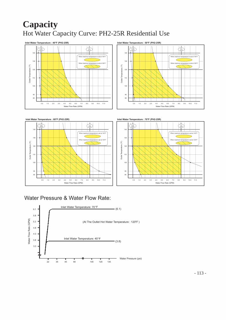
- 113 -
CapacityHot Water Capacity Curve: PH2-25R Residential Use
0.5 1.0 2.0 3.0 4.0 5.0 6.0 7.0 8.0 9.0 10.0 11.0
85
100
120
130
140
Inlet Water Temperature : 40°F (PH2-25R)
Water Flow Rate (GPM)
Out
let T
empe
ratu
re (°
F)
8.4 GPM
When maximum temperature is set at 140°F
When maximum temperature is set at 120°F
90
110
0.40 GPM
0.5 1.0 2.0 3.0 4.0 5.0 6.0 7.0 8.0 9.0 10.0 11.0
85
100
120
130
140
Inlet Water Temperature : 50°F (PH2-25R)
Water Flow Rate (GPM)
Out
let T
empe
ratu
re (°
F)
90
110
0.40 GPM
8.4 GPM
When maximum temperature is set at 140°F
When maximum temperature is set at 120°F
0.5 1.0 2.0 3.0 4.0 5.0 6.0 7.0 8.0 9.0 10.0 11.0
85
100
120
130
140
Inlet Water Temperature : 60°F (PH2-25R)
Water Flow Rate (GPM)
Out
let T
empe
ratu
re (°
F)
90
110
0.40 GPM
When maximum temperature is set at 140°F
When maximum temperature is set at 120°F
8.4 GPM
0.5 1.0 2.0 3.0 4.0 5.0 6.0 7.0 8.0 9.0 10.0 11.0
85
100
120
130
140
Inlet Water Temperature : 70°F (PH2-25R)
Water Flow Rate (GPM)
Out
let T
empe
ratu
re (°
F)
90
110
When maximum temperature is set at 140°F
When maximum temperature is set at 120°F
0.40 GPM
8.4 GPM
°F
°F
Water Pressure & Water Flow Rate:
Wat
er F
low
Rat
e (G
PM
)
Water Pressure (psi)
3.3
3.8
4.3
4.8
5.3
5.8
6.1Inlet Water Temperature: 70
Inlet Water Temperature: 40
(6.1)
(3.8)
22 35 45 60 105 120 135
(At The Outlet Hot Water Temperature : 120 )°F
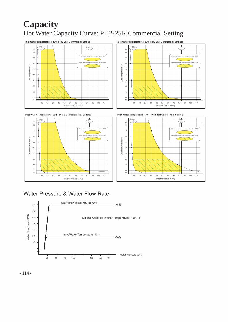
- 114 -
CapacityHot Water Capacity Curve: PH2-25R Commercial Setting
0.5 1.0 2.0 3.0 4.0 5.0 6.0 7.0 8.0 9.0 10.0 11.0
100
110
120
130
140
Inlet Water Temperature : 40°F (PH2-25R Commercial Setting)
Water Flow Rate (GPM)
Out
let T
empe
ratu
re (°
F)
150
160
170
180
185
85
8.4 GPM
When maximum temperature is set at 185°F
When maximum temperature is set at 120°F
0.40 GPM
0.5 1.0 2.0 3.0 4.0 5.0 6.0 7.0 8.0 9.0 10.0 11.0
100
110
120
130
140
Inlet Water Temperature : 50°F (PH2-25R Commercial Setting)
Water Flow Rate (GPM)
Out
let T
empe
ratu
re (°
F)
150
160
170
180
185
85
0.40 GPM
When maximum temperature is set at 185°F
When maximum temperature is set at 120°F
8.4 GPM
0.5 1.0 2.0 3.0 4.0 5.0 6.0 7.0 8.0 9.0 10.0 11.0
100
110
120
130
140
Inlet Water Temperature : 60°F (PH2-25R Commercial Setting)
Water Flow Rate (GPM)
Out
let T
empe
ratu
re (°
F)
150
160
170
180
185
85
When maximum temperature is set at 185°F
When maximum temperature is set at 120°F
0.40 GPM
8.4 GPM
0.5 1.0 2.0 3.0 4.0 5.0 6.0 7.0 8.0 9.0 10.0 11.0
100
110
120
130
140
Inlet Water Temperature : 70°F (PH2-25R Commercial Setting)
Water Flow Rate (GPM)
Out
let T
empe
ratu
re (°
F)
150
160
170
180
185
85
0.40 GPM
When maximum temperature is set at 185°F
When maximum temperature is set at 120°F
8.4 GPM
°F
°F
Water Pressure & Water Flow Rate:
Wat
er F
low
Rat
e (G
PM
)
Water Pressure (psi)
3.3
3.8
4.3
4.8
5.3
5.8
6.1Inlet Water Temperature: 70
Inlet Water Temperature: 40
(6.1)
(3.8)
22 35 45 60 105 120 135
(At The Outlet Hot Water Temperature : 120 )°F
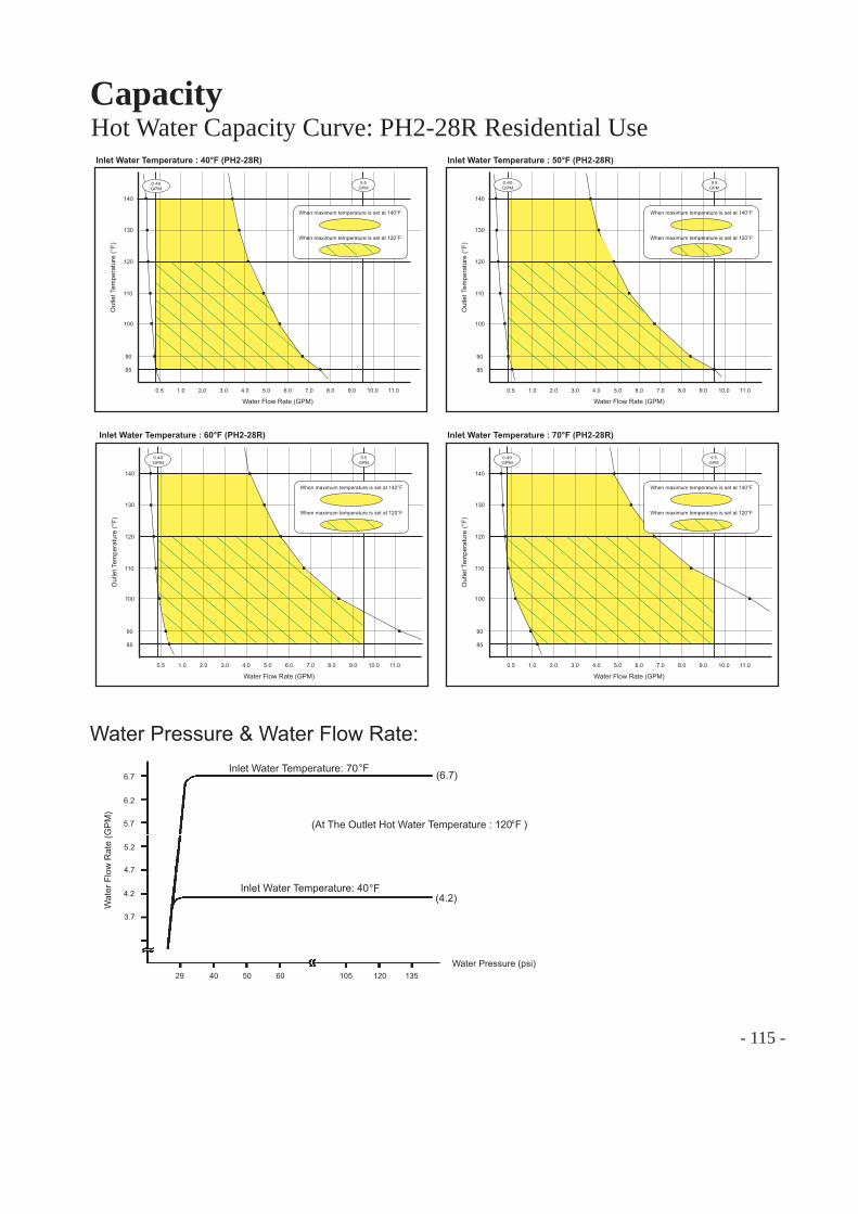
- 115 -
CapacityHot Water Capacity Curve: PH2-28R Residential Use
0.5 1.0 2.0 3.0 4.0 5.0 6.0 7.0 8.0 9.0 10.0 11.0
85
100
120
130
140
Inlet Water Temperature : 40°F (PH2-28R)
Water Flow Rate (GPM)
Out
let T
empe
ratu
re (°
F)
9.5 GPM
When maximum temperature is set at 140°F
When maximum temperature is set at 120°F
90
110
0.40 GPM
0.5 1.0 2.0 3.0 4.0 5.0 6.0 7.0 8.0 9.0 10.0 11.0
85
100
120
130
140
Inlet Water Temperature : 50°F (PH2-28R)
Water Flow Rate (GPM)
Out
let T
empe
ratu
re (°
F)
9.5 GPM
When maximum temperature is set at 140°F
When maximum temperature is set at 120°F
90
110
0.40 GPM
0.5 1.0 2.0 3.0 4.0 5.0 6.0 7.0 8.0 9.0 10.0 11.0
85
100
120
130
140
Inlet Water Temperature : 60°F (PH2-28R)
Water Flow Rate (GPM)
Out
let T
empe
ratu
re (°
F)
90
110
9.5 GPM
When maximum temperature is set at 140°F
When maximum temperature is set at 120°F
0.40 GPM
0.5 1.0 2.0 3.0 4.0 5.0 6.0 7.0 8.0 9.0 10.0 11.0
85
100
120
130
140
Inlet Water Temperature : 70°F (PH2-28R)
Water Flow Rate (GPM)
Out
let T
empe
ratu
re (°
F)
90
110
9.5 GPM
0.40 GPM
When maximum temperature is set at 140°F
When maximum temperature is set at 120°F
°F
°F
Water Pressure & Water Flow Rate:
Wat
er F
low
Rat
e (G
PM
)
Water Pressure (psi)
3.7
4.2
4.7
5.2
5.7
6.2
6.7Inlet Water Temperature: 70
Inlet Water Temperature: 40
(6.7)
(4.2)
29 40 50 60 105 120 135
(At The Outlet Hot Water Temperature : 120 )°F

- 116 -
CapacityHot Water Capacity Curve: PH2-28R Commercial Setting
0.5 1.0 2.0 3.0 4.0 5.0 6.0 7.0 8.0 9.0 10.0 11.0
100
110
120
130
140
Inlet Water Temperature : 40°F (PH2-28R Commercial Setting)
Water Flow Rate (GPM)
Out
let T
empe
ratu
re (°
F)
150
160
170
180
185
85
9.5 GPM
When maximum temperature is set at 185°F
When maximum temperature is set at 120°F
0.40 GPM
0.5 1.0 2.0 3.0 4.0 5.0 6.0 7.0 8.0 9.0 10.0 11.0
100
110
120
130
140
Inlet Water Temperature : 50°F (PH2-28R Commercial Setting)
Water Flow Rate (GPM)
Out
let T
empe
ratu
re (°
F)
150
160
170
180
185
85
9.5 GPM
0.40 GPM
When maximum temperature is set at 185°F
When maximum temperature is set at 120°F
0.5 1.0 2.0 3.0 4.0 5.0 6.0 7.0 8.0 9.0 10.0 11.0
100
110
120
130
140
Inlet Water Temperature : 60°F (PH2-28R Commercial Setting)
Water Flow Rate (GPM)
Out
let T
empe
ratu
re (°
F)
150
160
170
180
185
85
0.40 GPM
9.5 GPM
When maximum temperature is set at 185°F
When maximum temperature is set at 120°F
0.5 2.0 3.0 4.0 5.0 6.0 7.0 8.0 9.0 10.0 11.0
100
110
120
130
140
Inlet Water Temperature : 70°F (PH2-28R Commercial Setting)
Water Flow Rate (GPM)
Out
let T
empe
ratu
re (°
F)
150
160
170
180
185
85
9.5 GPM
1.0
0.40 GPM
When maximum temperature is set at 185°F
When maximum temperature is set at 120°F
°F
°F
Water Pressure & Water Flow Rate:
Wat
er F
low
Rat
e (G
PM
)
Water Pressure (psi)
3.7
4.2
4.7
5.2
5.7
6.2
6.7Inlet Water Temperature: 70
Inlet Water Temperature: 40
(6.7)
(4.2)
29 40 50 60 105 120 135
(At The Outlet Hot Water Temperature : 120 )°F
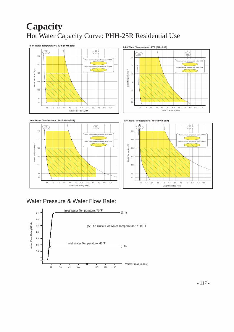
- 117 -
CapacityHot Water Capacity Curve: PHH-25R Residential Use
°F
°F
Water Pressure & Water Flow Rate:
Wat
er F
low
Rat
e (G
PM
)
Water Pressure (psi)
3.3
3.8
4.3
4.8
5.3
5.8
6.1Inlet Water Temperature: 70
Inlet Water Temperature: 40
(6.1)
(3.8)
22 35 45 60 105 120 135
(At The Outlet Hot Water Temperature : 120 )°F
0.5 1.0 2.0 3.0 4.0 5.0 6.0 7.0 8.0 9.0 10.0 11.0
85
100
120
130
140
Inlet Water Temperature : 40°F (PHH-25R)
Water Flow Rate (GPM)
Out
let T
empe
ratu
re (°
F)
8.5 GPM
When maximum temperature is set at 140°F
When maximum temperature is set at 120°F
90
110
0.40 GPM
0.5 1.0 2.0 3.0 4.0 5.0 6.0 7.0 8.0 9.0 10.0 11.0
85
100
120
130
140
Inlet Water Temperature : 50°F (PHH-25R)
Water Flow Rate (GPM)
Out
let T
empe
ratu
re (°
F)
90
110
0.40 GPM
8.5 GPM
When maximum temperature is set at 140°F
When maximum temperature is set at 120°F
0.5 1.0 2.0 3.0 4.0 5.0 6.0 7.0 8.0 9.0 10.0 11.0
85
100
120
130
140
Inlet Water Temperature : 60°F (PHH-25R)
Water Flow Rate (GPM)
Out
let T
empe
ratu
re (°
F)
90
110
0.40 GPM
8.5 GPM
When maximum temperature is set at 140°F
When maximum temperature is set at 120°F
0.5 1.0 2.0 3.0 4.0 5.0 6.0 7.0 8.0 9.0 10.0 11.0
85
100
120
130
140
Inlet Water Temperature : 70°F (PHH-25R)
Water Flow Rate (GPM)
Out
let T
empe
ratu
re (°
F)
90
110
8.5 GPM
0.40 GPM
When maximum temperature is set at 140°F
When maximum temperature is set at 120°F
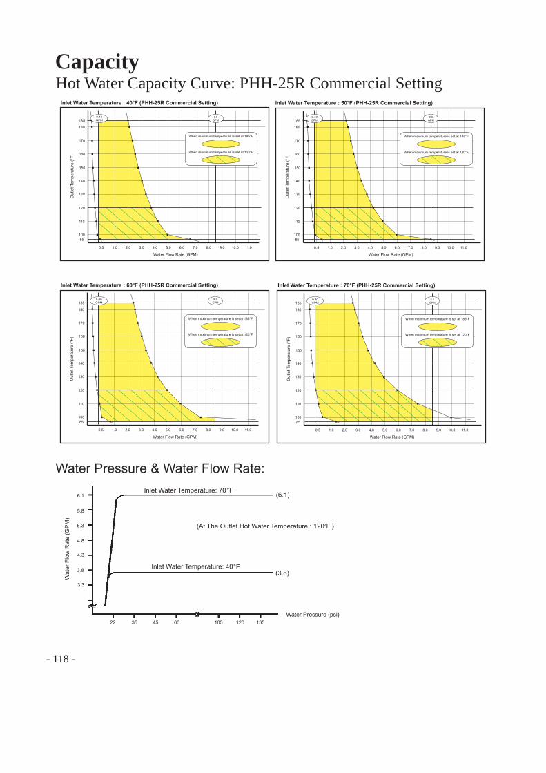
- 118 -
CapacityHot Water Capacity Curve: PHH-25R Commercial Setting
°F
°F
Water Pressure & Water Flow Rate:
Wat
er F
low
Rat
e (G
PM
)
Water Pressure (psi)
3.3
3.8
4.3
4.8
5.3
5.8
6.1Inlet Water Temperature: 70
Inlet Water Temperature: 40
(6.1)
(3.8)
22 35 45 60 105 120 135
(At The Outlet Hot Water Temperature : 120 )°F
0.5 1.0 2.0 3.0 4.0 5.0 6.0 7.0 8.0 9.0 10.0 11.0
100
110
120
130
140
Inlet Water Temperature : 40°F (PHH-25R Commercial Setting)
Water Flow Rate (GPM)
Out
let T
empe
ratu
re (°
F)
150
160
170
180
185
85
0.40 GPM
8.5 GPM
When maximum temperature is set at 185°F
When maximum temperature is set at 120°F
0.5 1.0 2.0 3.0 4.0 5.0 6.0 7.0 8.0 9.0 10.0 11.0
100
110
120
130
140
Inlet Water Temperature : 50°F (PHH-25R Commercial Setting)
Water Flow Rate (GPM)
Out
let T
empe
ratu
re (°
F)
150
160
170
180
185
85
0.40 GPM
8.5 GPM
When maximum temperature is set at 185°F
When maximum temperature is set at 120°F
0.5 1.0 2.0 3.0 4.0 5.0 6.0 7.0 8.0 9.0 10.0 11.0
100
110
120
130
140
Inlet Water Temperature : 60°F (PHH-25R Commercial Setting)
Water Flow Rate (GPM)
Out
let T
empe
ratu
re (°
F)
150
160
170
180
185
85
0.40 GPM
8.5 GPM
When maximum temperature is set at 185°F
When maximum temperature is set at 120°F
0.5 1.0 2.0 3.0 4.0 5.0 6.0 7.0 8.0 9.0 10.0 11.0
100
110
120
130
140
Inlet Water Temperature : 70°F (PHH-25R Commercial Setting)
Water Flow Rate (GPM)
Out
let T
empe
ratu
re (°
F)
150
160
170
180
185
85
0.40 GPM
8.5 GPM
When maximum temperature is set at 185°F
When maximum temperature is set at 120°F
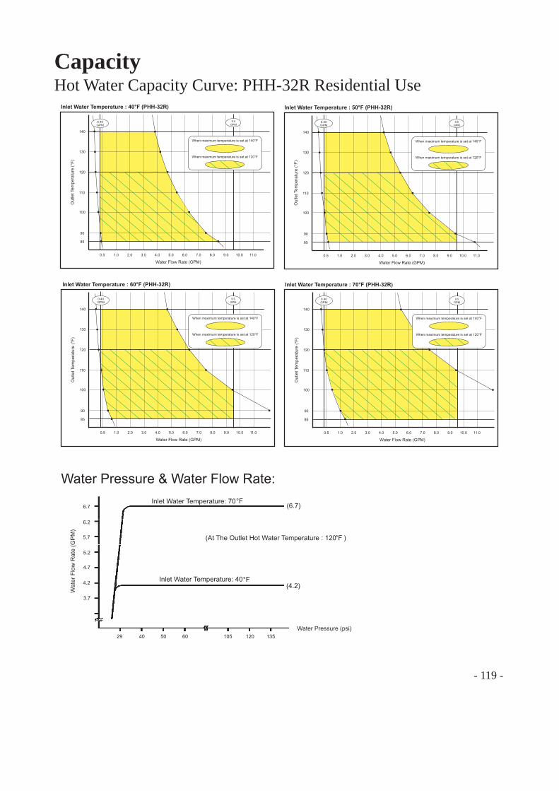
- 119 -
CapacityHot Water Capacity Curve: PHH-32R Residential Use
°F
°F
Water Pressure & Water Flow Rate:
Wat
er F
low
Rat
e (G
PM
)
Water Pressure (psi)
3.7
4.2
4.7
5.2
5.7
6.2
6.7Inlet Water Temperature: 70
Inlet Water Temperature: 40
(6.7)
(4.2)
29 40 50 60 105 120 135
(At The Outlet Hot Water Temperature : 120 )°F
0.5 1.0 2.0 3.0 4.0 5.0 6.0 7.0 8.0 9.0 10.0 11.0
85
100
120
130
140
Inlet Water Temperature : 40°F (PHH-32R)
Water Flow Rate (GPM)
Out
let T
empe
ratu
re (°
F)
9.5 GPM
90
110
0.40 GPM
When maximum temperature is set at 140°F
When maximum temperature is set at 120°F
0.5 1.0 2.0 3.0 4.0 5.0 6.0 7.0 8.0 9.0 10.0 11.0
85
100
120
130
140
Inlet Water Temperature : 50°F (PHH-32R)
Water Flow Rate (GPM)
Out
let T
empe
ratu
re (°
F)
90
110
0.40 GPM
When maximum temperature is set at 140°F
When maximum temperature is set at 120°F
9.5 GPM
0.5 1.0 2.0 3.0 4.0 5.0 6.0 7.0 8.0 9.0 10.0 11.0
85
100
120
130
140
Inlet Water Temperature : 70°F (PHH-32R)
Water Flow Rate (GPM)
Out
let T
empe
ratu
re (°
F)
90
110
0.40 GPM
When maximum temperature is set at 140°F
When maximum temperature is set at 120°F
9.5 GPM
0.5 1.0 2.0 3.0 4.0 5.0 6.0 7.0 8.0 9.0 10.0 11.0
85
100
120
130
140
Inlet Water Temperature : 60°F (PHH-32R)
Water Flow Rate (GPM)
Out
let T
empe
ratu
re (°
F)
90
110
0.40 GPM
When maximum temperature is set at 140°F
When maximum temperature is set at 120°F
9.5 GPM
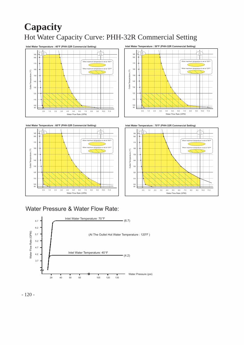
- 120 -
CapacityHot Water Capacity Curve: PHH-32R Commercial Setting
°F
°F
Water Pressure & Water Flow Rate:
Wat
er F
low
Rat
e (G
PM
)
Water Pressure (psi)
3.7
4.2
4.7
5.2
5.7
6.2
6.7Inlet Water Temperature: 70
Inlet Water Temperature: 40
(6.7)
(4.2)
29 40 50 60 105 120 135
(At The Outlet Hot Water Temperature : 120 )°F
0.5 1.0 2.0 3.0 4.0 5.0 6.0 7.0 8.0 9.0 10.0 11.0
100
110
120
130
140
Inlet Water Temperature : 40°F (PHH-32R Commercial Setting)
Water Flow Rate (GPM)
Out
let T
empe
ratu
re (°
F)
150
160
170
180
185
85
9.5 GPM
0.40 GPM
When maximum temperature is set at 185°F
When maximum temperature is set at 120°F
0.5 1.0 2.0 3.0 4.0 5.0 6.0 7.0 8.0 9.0 10.0 11.0
100
110
120
130
140
Inlet Water Temperature : 50°F (PHH-32R Commercial Setting)
Water Flow Rate (GPM)
Out
let T
empe
ratu
re (°
F)
150
160
170
180
185
85
0.40 GPM
9.5 GPM
When maximum temperature is set at 185°F
When maximum temperature is set at 120°F
0.5 1.0 2.0 3.0 4.0 5.0 6.0 7.0 8.0 9.0 10.0 11.0
100
110
120
130
140
Inlet Water Temperature : 60°F (PHH-32R Commercial Setting)
Water Flow Rate (GPM)
Out
let T
empe
ratu
re (°
F)
150
160
170
180
185
85
0.40 GPM
9.5 GPM
When maximum temperature is set at 185°F
When maximum temperature is set at 120°F
0.5 2.0 3.0 4.0 5.0 6.0 7.0 8.0 9.0 10.0 11.0
100
110
120
130
140
Inlet Water Temperature : 70°F (PHH-32R Commercial Setting)
Water Flow Rate (GPM)
Out
let T
empe
ratu
re (°
F)
150
160
170
180
185
85
1.0
0.40 GPM
9.5 GPM
When maximum temperature is set at 185°F
When maximum temperature is set at 120°F
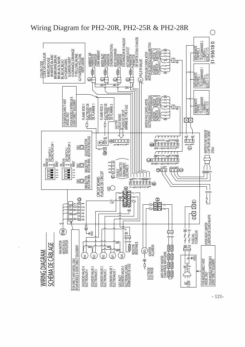
Wiring Diagram for PH2-20R, PH2-25R & PH2-28R
31-9
3618
0
VERT
/JAUN
EG/
Y:GR
EEN/
YELL
OW,
AC 120V
O:O
RANG
E,O
RANG
E
CODE
DE C
OULE
URCO
LOR C
ODE
MIN B
UTTO
NBO
UTON
MIN.
G/Yo
rGW
BOUT
ON M
AX.
BL
BLBL
LED
GG
MAX B
UTTO
NAD
JUSTER
BUTTO
N
BL
BOUT
ON DE
RÉGL
AGE BL
12345A
FOR I
NDOO
R,DIRE
CT-VE
NTMO
DEL O
NLY
POUR
MOD
ÈLE I
NTÉR
IEUR À
ÉVEN
T DIRE
CT SE
ULEM
ENT
43
21
YW
RBK
BLW
BLR
OY
FOR D
IRECT
-VENT
MOD
EL ON
LYPO
UR M
ODÈL
E À ÉV
ENT D
IRECT
SEUL
EMEN
TSW
3SW
2SW
1
U2 1
S13 2
W W
12
34
IJ
H
F
W W
23
41
B
R Y O W BRBK
12345678R Y O W BRBK
12345678
C9
RBR BK
BK WBK W
12
34
YWBK
12
3K
SV0
SV1
SV2
SV3
WBK
W
G/Y GYBK
IG
12
34
56
G
FM5
GY
W Y R RBKBK
R1234567
+PSVR1R2R3R4
BKBK -
WIRIN
G DIAG
RAM
SCHÉ
MA DE
CÂBL
AGE
MOTE
UR D
UVE
NTILA
TEUR
FAN
MOTO
R
ELEC
TROD
EIG
NITE
R
FUSE
(3A)
(UM
C-11
7)
CIRCU
IT BO
ARD
PLAQ
UE D
E CIRC
UIT
ÉLEC
TROD
EAL
LUME
UR
ANTI-
FROS
T HEA
TER
CHAU
FFAG
E ANT
I-GIVR
E
FUSIB
LE(3A
)
ON MARC
HE
OFF
ARRÉ
TCONT
ACTE
UR D
IP 1
DIP S
WITC
H 1
DIP S
WITC
H 2
CONT
ACTE
UR D
IP 2
ON MARC
HE
OFF
ARRÉ
T
ÉLECTR
OVALV
E DE D
ÉRIVAT
ION D'E
AUWA
TER VO
LUME C
ONTRO
L MOTO
RWA
TER BY
-PASS
CONT
ROL M
OTOR
MOTEU
R DE C
ONTRÔ
LE DU
VOLU
ME D'E
AU
R:RE
D,RO
UGE
W:W
HITE
,BLA
NCBR
:BRO
WN,
BRUN
BL:B
LUE,
BLEU
BK:B
LACK
,NO
IR
GY:G
RAY,
GRIS
G:GR
EEN,
VERT
Y:YE
LLOW
,JAUN
E
BK (USC
1-11
7)(U
SC2-
117)
WW
LIMITE
RLIM
ITEUR
MOTO
RMO
TEUR
LIMITE
RLIM
ITEUR
MOTO
RMO
TEUR
45
67
8
GY
R
BL
SV4
BK
BK
BK
BK
123V
TBL
MW
FLAM
E ROD
1ÉL
ECTR
ODE D
EDÉ
TECT
ION
DE FL
AMM
E 1
FLAM
E ROD
3ÉL
ECTR
ODE D
EDÉ
TECT
ION
DE FL
AMME
3
FOR I
NDOO
R,DIRE
CT-VE
NTMO
DEL O
NLY
POUR
MOD
ÈLE I
NTÉR
IEUR À
ÉVEN
T DIRE
CT SE
ULEM
ENT
RÉSIS
TANC
E
USUA
LLYDIS
CONN
ECTED
NORM
ALEME
NTDE
CONN
ECTE
BK
GND
GND
RESIS
TOR
SOLE
NOID
VALV
E 3ÉL
ECTR
OVAL
VE 3
SOLE
NOID
VALV
E 2ÉL
ECTR
OVAL
VE 2
ÉLEC
TROV
ALVE
1SO
LENO
ID VA
LVE 1
ÉLEC
TROV
ALVE
DANS
ADMI
SSIO
N DE
GAZ
GAS I
NLET
SOLE
NOID
VALV
E 0
OVER
HEA
T LIM
ITER
LIMITE
UR D
E SUR
CHAU
FFE
WATE
R FLO
W SE
NSOR
D'EAU
CAPT
EUR D
E DÉB
IT
P.G.F.
R VAL
VE
AMBIE
NT AI
RTH
ERMI
STOR
D'AIR
AMBIA
NT
THER
MISTO
RDE
SORT
IE D'
EAU
CHAU
DE
D'ECH
ANGE
UR DE
CHAL
EUR
HOT W
ATER
OUTL
ETTH
ERMI
STOR
THER
MISTO
R
HEAT
EXCH
ANGE
RTH
ERMI
STOR
D'ADM
ISSIO
N D'E
AUTH
ERMI
STOR
WATE
R INL
ETTH
ERMI
STOR
THER
MISTO
R
GAS T
YPE
CIRCU
IT BOA
RDPL
AQUE
DE CI
RCUIT
IMPR
IMÉ D
E TYP
E Â GA
Z
MAIN
REMO
TECO
NTRO
LTÉL
ÉCOM
MAND
E<<
MAIN
>>
BATH
REMO
TECO
NTRO
L 1BA
TH RE
MOTE
CONT
ROL 2
TÉLÉ
COMM
ANDE
1TÉ
LÉCO
MMAN
DE 2
<<BA
TH>>
<<BA
TH>>
SOLE
NOID
VALV
E 4ÉL
ECTR
OVAL
VE 4
GG
BLBL
BKR
YO
WBR
8
BKR
YO
WBR
8
- 121-
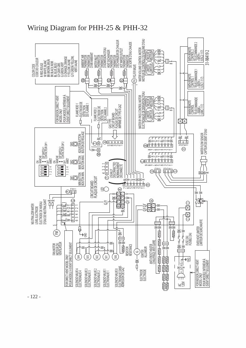
- 122 -
Wiring Diagram for PHH-25 & PHH-32
FLAM
E ROD
2ÉL
ECTR
ODE D
EDÉ
TECT
ION
DE FL
AMME
2
31-98
419 2
NEUT
RALIZ
ER W
ATER
LEVE
L ELE
CTRO
DE
RR
ÉLEC
TROD
E DE N
IVEAU
D’EA
U DE N
EUTR
ALISA
NT
2 1
P
GRÉ
SISTA
NCE
VERT
/JAUN
EG/
Y: GRE
EN/ Y
ELLO
W,
AC 120V
O: OR
ANGE
, ORA
NGE
USUA
LLYDI
SCON
NECT
EDNO
RMAL
EMEN
TDÉ
CONN
ECTÉ
CODE
DE C
OULE
URCO
LOR C
ODE
MIN B
UTTO
NBO
UTON
MIN
.
G/Y o
r GWBK
BOUT
ON M
AX.
BL
BLBL
LED
GG
MAX B
UTTO
NAD
JUST
ER BU
TTON BL
BOUT
ON D
E RÉG
LAGE
BL
GG
BLBL
12345A
`
FOR I
NDOO
R, DI
RECT
-VENT
MODE
L ONL
YPO
UR M
ODEL
E INT
ERIÉU
R ÀÉV
ENT D
IRECT
SEUL
EMEN
T
43
21
YW
RBK
BLW
BLR
OY
`FO
R DIRE
CT-VE
NT M
ODEL
ONL
YPO
UR M
ODEL
E À ÉV
ENT D
IRECT
SEUL
EMEN
T
W
SW3
SW2
SW1
GND
BK
U2 1
S13 2
W W
12
34
IJ
H
F
RY
OW
BRW W
23
41
8
B
R Y O W BRBK
12345678R Y O W BRBK
12345678
C9
BKR
YO
WBR
RBR BK
BK WGN
D
BK W
12
34
YWBK
12
3K
SV0
SV1
SV2
SV3
WBK
W
G/Y
GY
BKIG
W WW
12
34
56
G
FM5
GY
W R RBKBK
R1234567
PSVR1R2R3R4
BK
BK − +
MOTE
UR D
UVE
NTILA
TEUR
FAN M
OTOR
RESIS
TOR
ELEC
TROD
EIG
NITE
R
FUSE
(3A)
(UMC
-117)
CIRCU
IT BO
ARD
PLAQ
UE D
E CIRC
UIT
SOLE
NOID
VALV
E 3ÉL
ECTR
OVAL
VE 3
SOLE
NOID
VALV
E 2ÉL
ECTR
OVAL
VE 2
ÉLEC
TROV
ALVE
1SO
LENO
ID VA
LVE 1
ÉLEC
TROV
ALVE
DAN
SAD
MISS
ION D
E GAZ
SOLE
NOID
VALV
E 0
ELEC
TROD
EAL
LUME
UR
ANTI-
FROS
T HEA
TER
CHAU
FFAG
E ANT
I-GIVR
E
FUSIB
LE (3
A)
OVER
HEAT
LIMI
TER
LIMITE
UR D
E SUR
CHAU
FFE
WATE
R FLO
W SE
NSOR
CAPT
EUR D
E DÉB
IT D’
EAU
P.G.F.R
VALV
E
ON MARC
HE
OFF
ARRÊ
TCONT
ACTE
UR D
IP 1
DIP S
WITC
H 1
DIP S
WITC
H 2CO
NTAC
TEUR
DIP
2
ON MARC
HE
OFF
ARRÊ
T
ÉLEC
TROV
ALVE
DE D
ÉRIVA
TION D
’EAU
WATE
R VOL
UME C
ONTR
OL M
OTOR
WATE
R BY-P
ASS C
ONTR
OL M
OTOR
AMBIE
NT AI
RTH
ERMI
STOR
THER
MIST
ORDE
SORT
IE D’
EAU C
HAUD
E
HOT W
ATER
OUT
LET
THER
MIST
OR
THER
MIST
ORD’
ECHA
NGEU
R DE C
HALE
UR
HEAT
EXCH
ANGE
RTH
ERMI
STOR
THER
MIST
ORD’
ADMI
SSIO
N D'EA
U
WATE
R INL
ETTH
ERMI
STOR
THER
MIST
ORD’
AIR AM
BIANT
GAS T
YPE
CIRCU
IT BO
ARD
PLAQ
UE D
E CIRC
UIT
IMPR
IMÉ D
E TYP
E Â GA
Z
MOTE
UR D
E CON
TRÔL
E DU V
OLUM
E D’EA
U
R: RE
D, RO
UGE
W: W
HITE
, BLA
NCBR
: BRO
WN, B
RUN
BL: B
LUE, B
LEU
BK: B
LACK
, NOI
R
MAIN
REMO
TECO
NTRO
L
GY: G
RAY, G
RIS
TÉLÉ
COMM
ANDE
G: GR
EEN,
VERT
Y: YEL
LOW,
JAUN
E
« MAIN
»
BK BATH
REMO
TECO
NTRO
L 1BA
TH RE
MOTE
CONT
ROL 2
TÉLÉ
COMM
ANDE
1TÉ
LÉCO
MMAN
DE 2
« BAT
H »« B
ATH »
(USC
1-117
)(U
SC2-1
17)
()
WW
LIMITE
RLIM
ITEUR
MOTO
RMO
TEUR
8
LIMITE
RLIM
ITEUR
MOTO
RMO
TEUR
45
67
8
GY
R
BL
SV4
SOLE
NOID
VALV
E 4ÉL
ECTR
OVAL
VE 4
BK
BK
BK
BK
123V
TBL
MW
FLAM
E ROD
1ÉL
ECTR
ODE D
EDÉ
TECT
ION
DE FL
AMME
1
FOR I
NDOO
R, DI
RECT
-VENT
MODE
L ONL
YPO
UR M
ODÈL
E INT
ÉRIEU
R ÀÉV
ENT D
IRECT
SEUL
EMEN
T
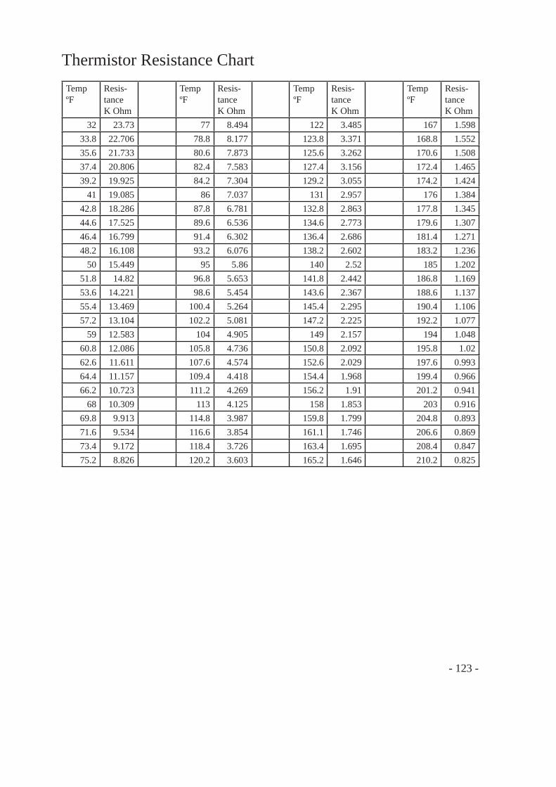
Thermistor Resistance ChartTempºF
Resis-tanceK Ohm
TempºF
Resis-tanceK Ohm
TempºF
Resis-tanceK Ohm
TempºF
Resis-tanceK Ohm
32 23.73 77 8.494 122 3.485 167 1.59833.8 22.706 78.8 8.177 123.8 3.371 168.8 1.55235.6 21.733 80.6 7.873 125.6 3.262 170.6 1.50837.4 20.806 82.4 7.583 127.4 3.156 172.4 1.46539.2 19.925 84.2 7.304 129.2 3.055 174.2 1.424
41 19.085 86 7.037 131 2.957 176 1.38442.8 18.286 87.8 6.781 132.8 2.863 177.8 1.34544.6 17.525 89.6 6.536 134.6 2.773 179.6 1.30746.4 16.799 91.4 6.302 136.4 2.686 181.4 1.27148.2 16.108 93.2 6.076 138.2 2.602 183.2 1.236
50 15.449 95 5.86 140 2.52 185 1.20251.8 14.82 96.8 5.653 141.8 2.442 186.8 1.16953.6 14.221 98.6 5.454 143.6 2.367 188.6 1.13755.4 13.469 100.4 5.264 145.4 2.295 190.4 1.10657.2 13.104 102.2 5.081 147.2 2.225 192.2 1.077
59 12.583 104 4.905 149 2.157 194 1.04860.8 12.086 105.8 4.736 150.8 2.092 195.8 1.0262.6 11.611 107.6 4.574 152.6 2.029 197.6 0.99364.4 11.157 109.4 4.418 154.4 1.968 199.4 0.96666.2 10.723 111.2 4.269 156.2 1.91 201.2 0.941
68 10.309 113 4.125 158 1.853 203 0.91669.8 9.913 114.8 3.987 159.8 1.799 204.8 0.89371.6 9.534 116.6 3.854 161.1 1.746 206.6 0.86973.4 9.172 118.4 3.726 163.4 1.695 208.4 0.84775.2 8.826 120.2 3.603 165.2 1.646 210.2 0.825
- 123 -
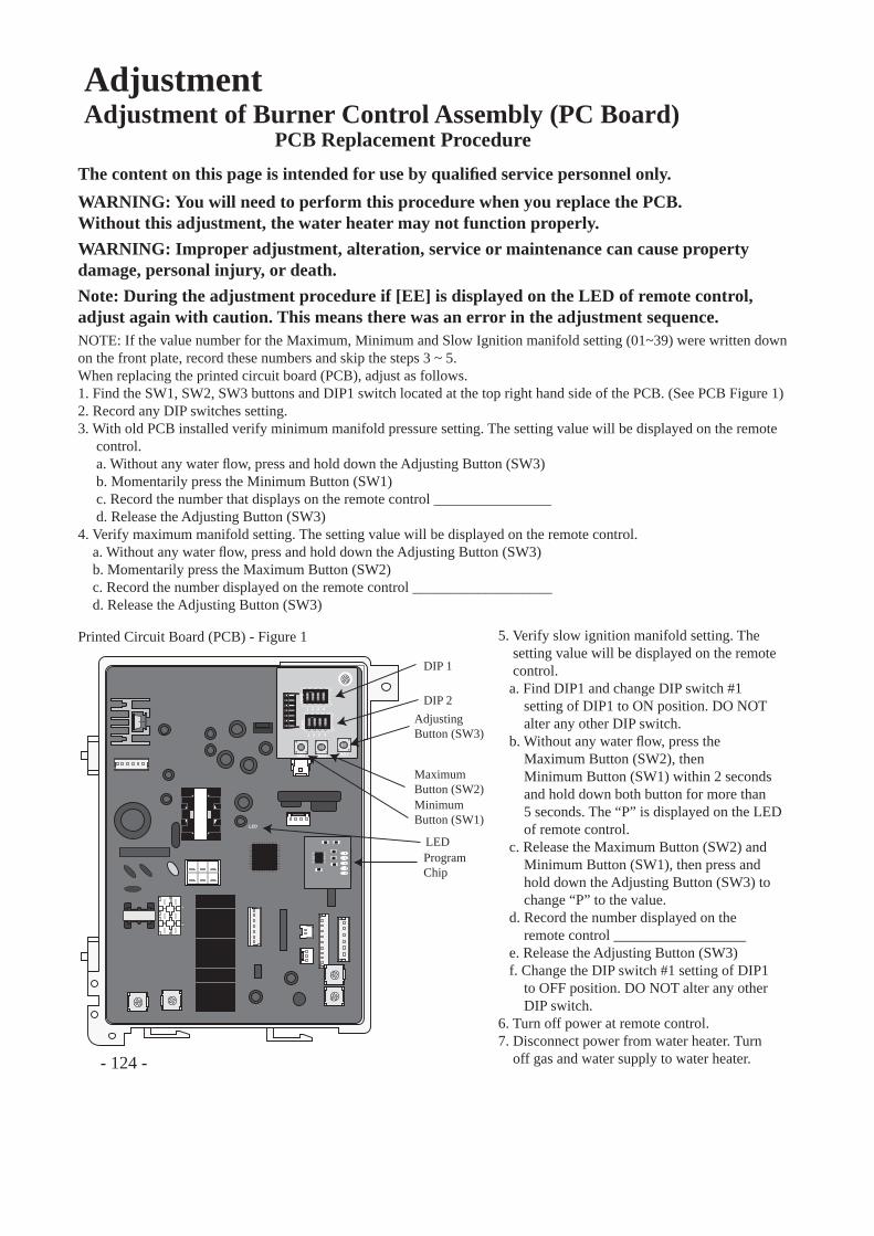
- 124 -
AdjustmentAdjustment of Burner Control Assembly (PC Board)
The content on this page is intended for use by qualifi ed service personnel only.
PCB Replacement Procedure
WARNING: You will need to perform this procedure when you replace the PCB.Without this adjustment, the water heater may not function properly.WARNING: Improper adjustment, alteration, service or maintenance can cause property damage, personal injury, or death.Note: During the adjustment procedure if [EE] is displayed on the LED of remote control, adjust again with caution. This means there was an error in the adjustment sequence.NOTE: If the value number for the Maximum, Minimum and Slow Ignition manifold setting (01~39) were written down on the front plate, record these numbers and skip the steps 3 ~ 5.When replacing the printed circuit board (PCB), adjust as follows.1. Find the SW1, SW2, SW3 buttons and DIP1 switch located at the top right hand side of the PCB. (See PCB Figure 1)2. Record any DIP switches setting.3. With old PCB installed verify minimum manifold pressure setting. The setting value will be displayed on the remote control. a. Without any water fl ow, press and hold down the Adjusting Button (SW3) b. Momentarily press the Minimum Button (SW1) c. Record the number that displays on the remote control ________________ d. Release the Adjusting Button (SW3)4. Verify maximum manifold setting. The setting value will be displayed on the remote control. a. Without any water fl ow, press and hold down the Adjusting Button (SW3) b. Momentarily press the Maximum Button (SW2) c. Record the number displayed on the remote control ___________________ d. Release the Adjusting Button (SW3)
ON
1 2 3 4
ON
OFF
ON
1 2 3 4
ON
OFF
1 2 3 4
1 2 3 4
DIP
2D
IP1
MIN MAX ADJ
LED
DIP 1
DIP 2AdjustingButton (SW3)
ProgramChip
MaximumButton (SW2)MinimumButton (SW1)
LED
Printed Circuit Board (PCB) - Figure 1 5. Verify slow ignition manifold setting. The setting value will be displayed on the remote control. a. Find DIP1 and change DIP switch #1 setting of DIP1 to ON position. DO NOT alter any other DIP switch. b. Without any water fl ow, press the Maximum Button (SW2), then Minimum Button (SW1) within 2 seconds and hold down both button for more than 5 seconds. The “P” is displayed on the LED of remote control. c. Release the Maximum Button (SW2) and Minimum Button (SW1), then press and hold down the Adjusting Button (SW3) to change “P” to the value. d. Record the number displayed on the remote control __________________ e. Release the Adjusting Button (SW3) f. Change the DIP switch #1 setting of DIP1 to OFF position. DO NOT alter any other DIP switch.6. Turn off power at remote control.7. Disconnect power from water heater. Turn off gas and water supply to water heater.
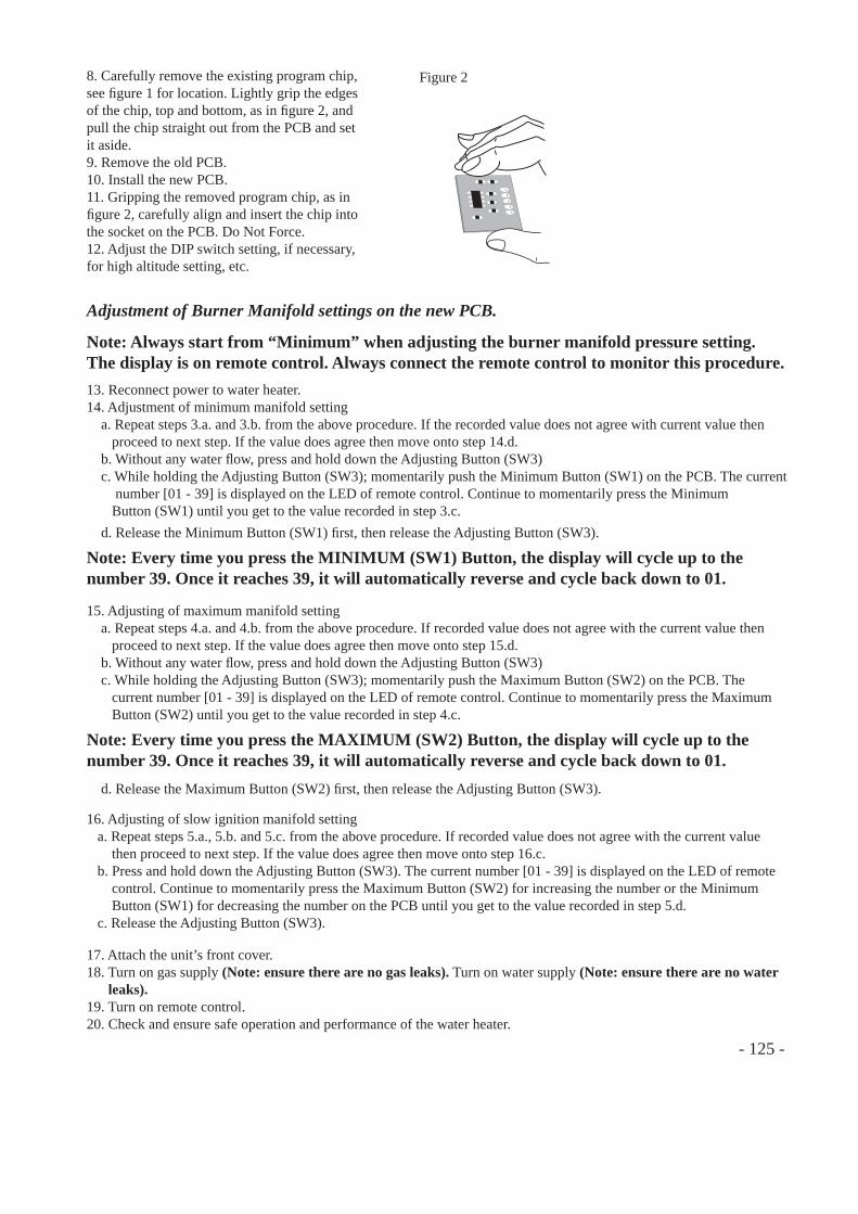
- 125 -
Adjustment of Burner Manifold settings on the new PCB.
Note: Always start from “Minimum” when adjusting the burner manifold pressure setting. The display is on remote control. Always connect the remote control to monitor this procedure.13. Reconnect power to water heater.14. Adjustment of minimum manifold setting a. Repeat steps 3.a. and 3.b. from the above procedure. If the recorded value does not agree with current value then proceed to next step. If the value does agree then move onto step 14.d. b. Without any water fl ow, press and hold down the Adjusting Button (SW3) c. While holding the Adjusting Button (SW3); momentarily push the Minimum Button (SW1) on the PCB. The current number [01 - 39] is displayed on the LED of remote control. Continue to momentarily press the Minimum Button (SW1) until you get to the value recorded in step 3.c.
Note: Every time you press the MINIMUM (SW1) Button, the display will cycle up to the number 39. Once it reaches 39, it will automatically reverse and cycle back down to 01.
d. Release the Minimum Button (SW1) fi rst, then release the Adjusting Button (SW3).
15. Adjusting of maximum manifold setting a. Repeat steps 4.a. and 4.b. from the above procedure. If recorded value does not agree with the current value then proceed to next step. If the value does agree then move onto step 15.d. b. Without any water fl ow, press and hold down the Adjusting Button (SW3) c. While holding the Adjusting Button (SW3); momentarily push the Maximum Button (SW2) on the PCB. The current number [01 - 39] is displayed on the LED of remote control. Continue to momentarily press the Maximum Button (SW2) until you get to the value recorded in step 4.c.
Note: Every time you press the MAXIMUM (SW2) Button, the display will cycle up to the number 39. Once it reaches 39, it will automatically reverse and cycle back down to 01. d. Release the Maximum Button (SW2) fi rst, then release the Adjusting Button (SW3).
17. Attach the unit’s front cover.18. Turn on gas supply (Note: ensure there are no gas leaks). Turn on water supply (Note: ensure there are no water leaks). 19. Turn on remote control.20. Check and ensure safe operation and performance of the water heater.
8. Carefully remove the existing program chip, see fi gure 1 for location. Lightly grip the edges of the chip, top and bottom, as in fi gure 2, and pull the chip straight out from the PCB and set it aside.9. Remove the old PCB.10. Install the new PCB.11. Gripping the removed program chip, as in fi gure 2, carefully align and insert the chip into the socket on the PCB. Do Not Force.12. Adjust the DIP switch setting, if necessary, for high altitude setting, etc.
Figure 2
16. Adjusting of slow ignition manifold setting a. Repeat steps 5.a., 5.b. and 5.c. from the above procedure. If recorded value does not agree with the current value then proceed to next step. If the value does agree then move onto step 16.c. b. Press and hold down the Adjusting Button (SW3). The current number [01 - 39] is displayed on the LED of remote control. Continue to momentarily press the Maximum Button (SW2) for increasing the number or the Minimum Button (SW1) for decreasing the number on the PCB until you get to the value recorded in step 5.d. c. Release the Adjusting Button (SW3).

- 126 -
Adjusting of Burner Manifold setting on the new PCB if the old PCB was completely broken or you could not get the value number [01 - 39].
Note: During the adjustment procedure if [EE] is displayed on the LED of remote control, adjust again with caution. This means there was an error in the adjustment sequence.
1. Turn off power at remote control. Disconnect power from water heater. Turn off gas and water supply to water heater.2. Record any DIP switches setting.
3. Carefully remove the existing program chip, see fi gure 1 for location. Lightly grip the edges of the chip, top and bottom, as in fi gure 2, and pull the chip straight out from the PCB and set it aside.4. Remove the old PCB.5. Install the new PCB.6. Gripping the removed program chip, as in fi gure 2, carefully align and insert the chip into the socket on the PCB. Do Not Force.7. Adjust the DIP switch setting, if necessary, for high altitude setting, etc.
Figure 2
8. Remove the plug for the manifold pressure and connect the manometer.9. Reconnect power to water heater.10. Do Not turn on remote control.
Note: Always start from “Minimum” when adjusting the burner manifold pressure setting. 11. Adjustment of manifold pressure Measurement of Fan Pressure Measure the fan pressure before adjusting the burner manifold pressure. The fan pressure differs depending on models, types of gas or installation condition. Measure the fan pressure at each installation site. (1) Measurement of minimum capacity. a. At the condition that the remote control is off and with any water fl ow, press and hold down the Minimum Button (SW1) on the PCB. b. Using the manometer, measure and record the minimum fan pressure (within 20 seconds). (2) Measurement of maximum capacity. a. At the condition that the remote control is off and with any water fl ow, press and hold down the Maximum Button (SW2) on the PCB. b. Using the manometer, measure and record the maximum fan pressure (within 20 seconds).
12. Adjustment of minimum manifold setting a. Turn on gas supply (Note: ensure there are no gas leaks). Turn on water supply (Note: ensure there are no water leaks). b. Turn on remote control. c. Open the hot water tap gradually until the water heater ignites at the minimum operating water fl ow. d. Press and hold down the Adjusting Button (SW3). e. While holding the Adjusting Button (SW3); momentarily push the Minimum Button (SW1) on the PCB. (Note: It becomes to the minimum setting forcibly when the water is fl ow.) Using the manometer, adjust the minimum manifold pressure to the standard pressure (see table below) plus the previous recorded minimum fan pressure in step 11. (1) b. f. Every time you press the Minimum Button (SW1), the displayed value is [UP] or [DOWN]. Adjust the value at the manometer. g. After adjusted, release the Minimum Button (SW1) fi rst, then release the Adjusting Button (SW3).
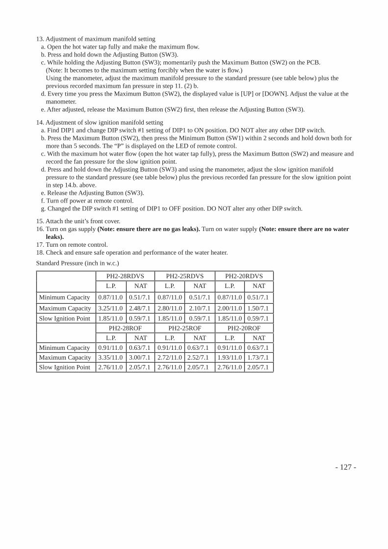
- 127 -
13. Adjustment of maximum manifold setting a. Open the hot water tap fully and make the maximum fl ow. b. Press and hold down the Adjusting Button (SW3). c. While holding the Adjusting Button (SW3); momentarily push the Maximum Button (SW2) on the PCB. (Note: It becomes to the maximum setting forcibly when the water is fl ow.) Using the manometer, adjust the maximum manifold pressure to the standard pressure (see table below) plus the previous recorded maximum fan pressure in step 11. (2) b. d. Every time you press the Maximum Button (SW2), the displayed value is [UP] or [DOWN]. Adjust the value at the manometer. e. After adjusted, release the Maximum Button (SW2) fi rst, then release the Adjusting Button (SW3).
14. Adjustment of slow ignition manifold setting a. Find DIP1 and change DIP switch #1 setting of DIP1 to ON position. DO NOT alter any other DIP switch. b. Press the Maximum Button (SW2), then press the Minimum Button (SW1) within 2 seconds and hold down both for more than 5 seconds. The “P” is displayed on the LED of remote control. c. With the maximum hot water fl ow (open the hot water tap fully), press the Maximum Button (SW2) and measure and record the fan pressure for the slow ignition point. d. Press and hold down the Adjusting Button (SW3) and using the manometer, adjust the slow ignition manifold pressure to the standard pressure (see table below) plus the previous recorded fan pressure for the slow ignition point in step 14.b. above. e. Release the Adjusting Button (SW3). f. Turn off power at remote control. g. Changed the DIP switch #1 setting of DIP1 to OFF position. DO NOT alter any other DIP switch.
15. Attach the unit’s front cover.16. Turn on gas supply (Note: ensure there are no gas leaks). Turn on water supply (Note: ensure there are no water leaks).17. Turn on remote control.18. Check and ensure safe operation and performance of the water heater.Standard Pressure (inch in w.c.)
PH2-28RDVS PH2-25RDVS PH2-20RDVSL.P. NAT L.P. NAT L.P. NAT
Minimum Capacity 0.87/11.0 0.51/7.1 0.87/11.0 0.51/7.1 0.87/11.0 0.51/7.1
Maximum Capacity 3.25/11.0 2.48/7.1 2.80/11.0 2.10/7.1 2.00/11.0 1.50/7.1Slow Ignition Point 1.85/11.0 0.59/7.1 1.85/11.0 0.59/7.1 1.85/11.0 0.59/7.1
PH2-28ROF PH2-25ROF PH2-20ROFL.P. NAT L.P. NAT L.P. NAT
Minimum Capacity 0.91/11.0 0.63/7.1 0.91/11.0 0.63/7.1 0.91/11.0 0.63/7.1Maximum Capacity 3.35/11.0 3.00/7.1 2.72/11.0 2.52/7.1 1.93/11.0 1.73/7.1Slow Ignition Point 2.76/11.0 2.05/7.1 2.76/11.0 2.05/7.1 2.76/11.0 2.05/7.1
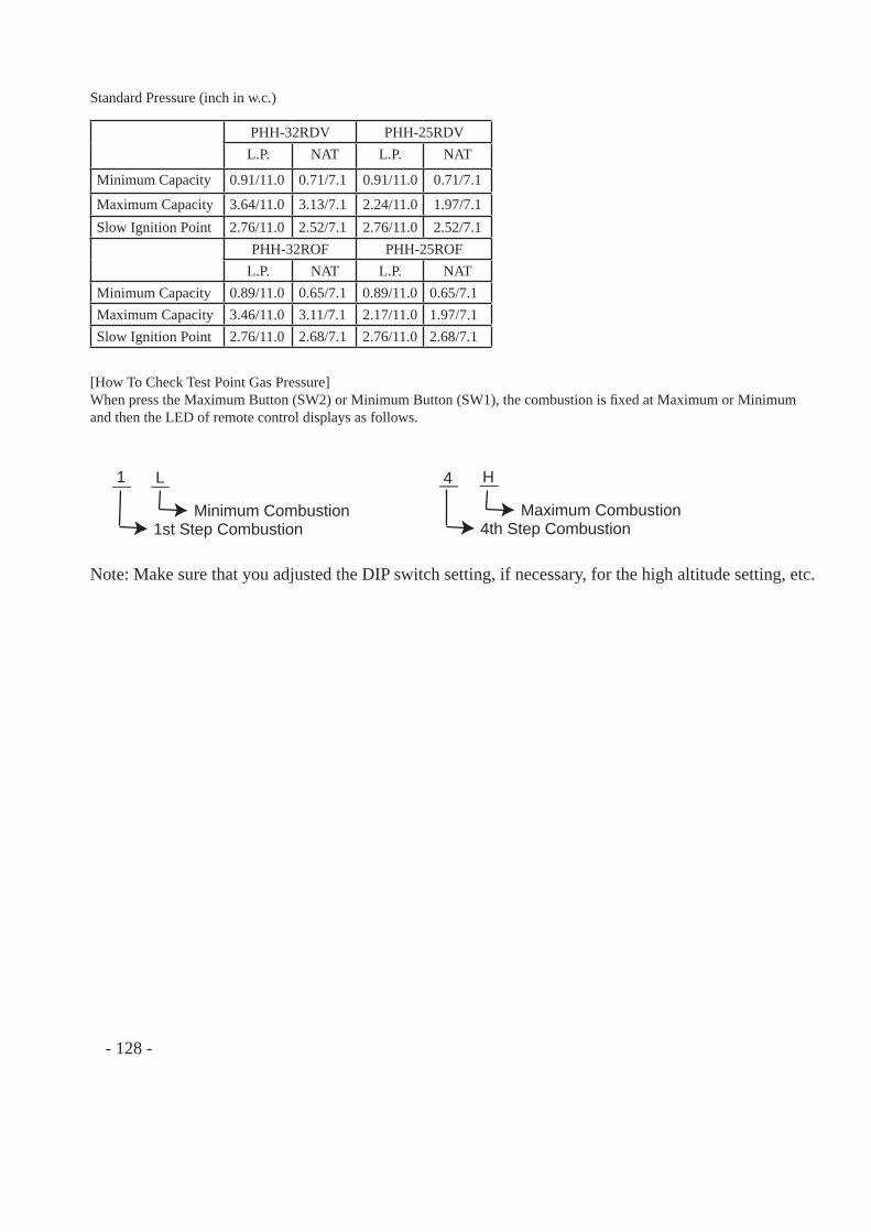
[How To Check Test Point Gas Pressure]When press the Maximum Button (SW2) or Minimum Button (SW1), the combustion is fi xed at Maximum or Minimum and then the LED of remote control displays as follows.
1__ L__
Minimum Combustion1st Step Combustion
4__ H__
Maximum Combustion4th Step Combustion
Note: Make sure that you adjusted the DIP switch setting, if necessary, for the high altitude setting, etc.
Standard Pressure (inch in w.c.)
PHH-32RDV PHH-25RDVL.P. NAT L.P. NAT
Minimum Capacity 0.91/11.0 0.71/7.1 0.91/11.0 0.71/7.1
Maximum Capacity 3.64/11.0 3.13/7.1 2.24/11.0 1.97/7.1Slow Ignition Point 2.76/11.0 2.52/7.1 2.76/11.0 2.52/7.1
PHH-32ROF PHH-25ROFL.P. NAT L.P. NAT
Minimum Capacity 0.89/11.0 0.65/7.1 0.89/11.0 0.65/7.1Maximum Capacity 3.46/11.0 3.11/7.1 2.17/11.0 1.97/7.1Slow Ignition Point 2.76/11.0 2.68/7.1 2.76/11.0 2.68/7.1
- 128 -
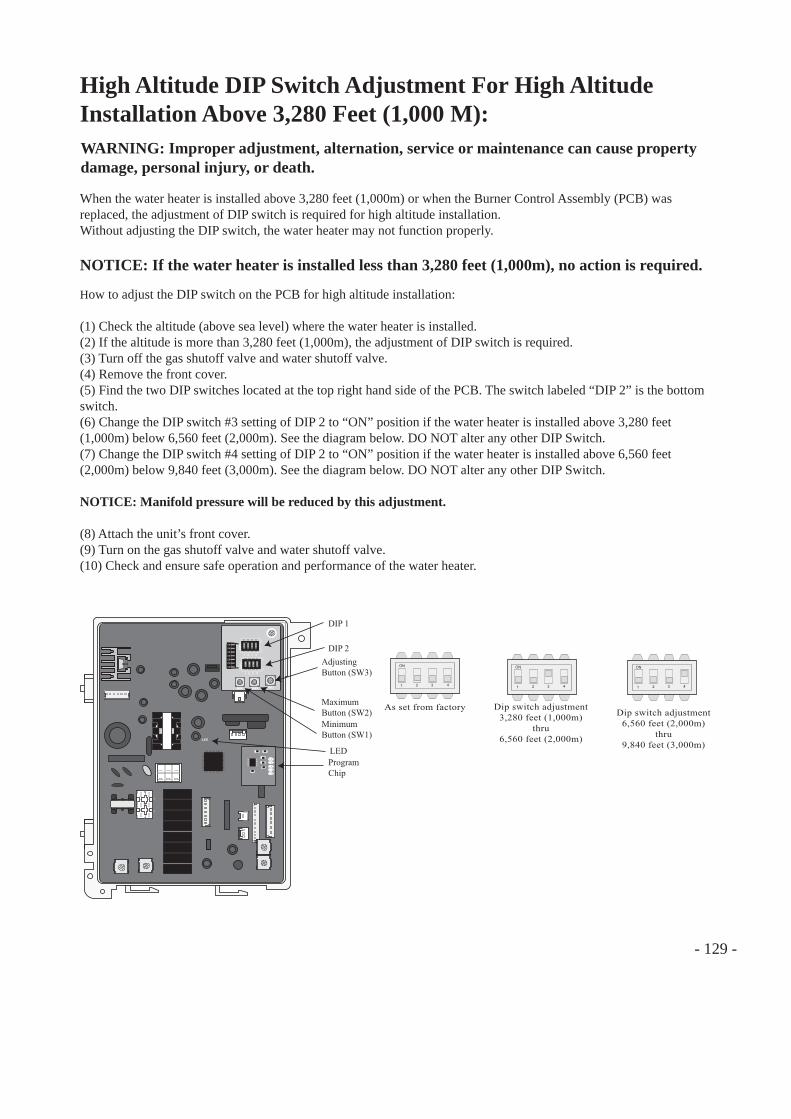
- 129 -
High Altitude DIP Switch Adjustment For High Altitude Installation Above 3,280 Feet (1,000 M):WARNING: Improper adjustment, alternation, service or maintenance can cause property damage, personal injury, or death.
When the water heater is installed above 3,280 feet (1,000m) or when the Burner Control Assembly (PCB) was replaced, the adjustment of DIP switch is required for high altitude installation.Without adjusting the DIP switch, the water heater may not function properly.
NOTICE: If the water heater is installed less than 3,280 feet (1,000m), no action is required.
How to adjust the DIP switch on the PCB for high altitude installation:
(1) Check the altitude (above sea level) where the water heater is installed.(2) If the altitude is more than 3,280 feet (1,000m), the adjustment of DIP switch is required.(3) Turn off the gas shutoff valve and water shutoff valve.(4) Remove the front cover.(5) Find the two DIP switches located at the top right hand side of the PCB. The switch labeled “DIP 2” is the bottom switch.(6) Change the DIP switch #3 setting of DIP 2 to “ON” position if the water heater is installed above 3,280 feet (1,000m) below 6,560 feet (2,000m). See the diagram below. DO NOT alter any other DIP Switch.(7) Change the DIP switch #4 setting of DIP 2 to “ON” position if the water heater is installed above 6,560 feet (2,000m) below 9,840 feet (3,000m). See the diagram below. DO NOT alter any other DIP Switch.
NOTICE: Manifold pressure will be reduced by this adjustment.
(8) Attach the unit’s front cover.(9) Turn on the gas shutoff valve and water shutoff valve.(10) Check and ensure safe operation and performance of the water heater.
ON
1 2 3 4
ON
OFF
ON
1 2 3 4
ON
OFF
1 2 3 4
1 2 3 4
DIP2
DIP1
MIN MAX ADJ
LED
DIP 1
DIP 2AdjustingButton (SW3)
ProgramChip
MaximumButton (SW2)MinimumButton (SW1)
LED
Dip switch adjustment3,280 feet (1,000m)
thru6,560 feet (2,000m)
ON
1 2 3 4
As set from factory
ON
1 2 3 4
ON
1 2 3 4
Dip switch adjustment6,560 feet (2,000m)
thru9,840 feet (3,000m)
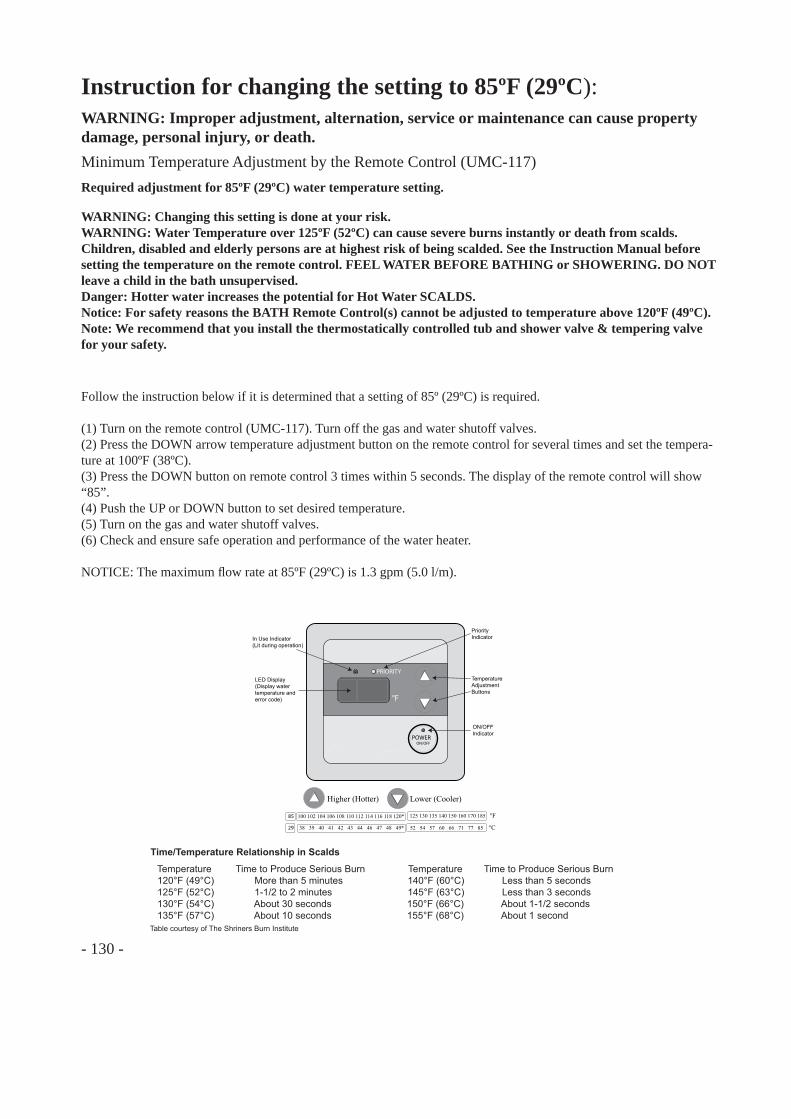
- 130 -
Instruction for changing the setting to 85ºF (29ºC):WARNING: Improper adjustment, alternation, service or maintenance can cause property damage, personal injury, or death.Minimum Temperature Adjustment by the Remote Control (UMC-117)
Follow the instruction below if it is determined that a setting of 85º (29ºC) is required.
(1) Turn on the remote control (UMC-117). Turn off the gas and water shutoff valves.(2) Press the DOWN arrow temperature adjustment button on the remote control for several times and set the tempera-ture at 100ºF (38ºC).(3) Press the DOWN button on remote control 3 times within 5 seconds. The display of the remote control will show “85”.(4) Push the UP or DOWN button to set desired temperature.(5) Turn on the gas and water shutoff valves.(6) Check and ensure safe operation and performance of the water heater.
NOTICE: The maximum fl ow rate at 85ºF (29ºC) is 1.3 gpm (5.0 l/m).
WARNING: Changing this setting is done at your risk.WARNING: Water Temperature over 125ºF (52ºC) can cause severe burns instantly or death from scalds. Children, disabled and elderly persons are at highest risk of being scalded. See the Instruction Manual before setting the temperature on the remote control. FEEL WATER BEFORE BATHING or SHOWERING. DO NOT leave a child in the bath unsupervised.Danger: Hotter water increases the potential for Hot Water SCALDS.Notice: For safety reasons the BATH Remote Control(s) cannot be adjusted to temperature above 120ºF (49ºC).Note: We recommend that you install the thermostatically controlled tub and shower valve & tempering valve for your safety.
°F
PRIORITY
POWERON/OFF
Higher (Hotter) Lower (Cooler)
In Use Indicator(Lit during operation)
LED Display(Display watertemperature and error code)
PriorityIndicator
TemperatureAdjustmentButtons
ON/OFFIndicator
100 102 104 106 108 110 112 114 116 118 120*
38 39 40 41 42 43 44 46 47 48 49*
85
29
125 130 135 140 150 160 170 185 °F
52 54 57 60 66 71 77 85 °C
Temperature Time to Produce Serious Burn Temperature Time to Produce Serious Burn 120°F (49°C) More than 5 minutes 140°F (60°C) Less than 5 seconds 125°F (52°C) 1-1/2 to 2 minutes 145°F (63°C) Less than 3 seconds 130°F (54°C) About 30 seconds 150°F (66°C) About 1-1/2 seconds 135°F (57°C) About 10 seconds 155°F (68°C) About 1 secondTable courtesy of The Shriners Burn Institute
Time/Temperature Relationship in Scalds
Required adjustment for 85ºF (29ºC) water temperature setting.
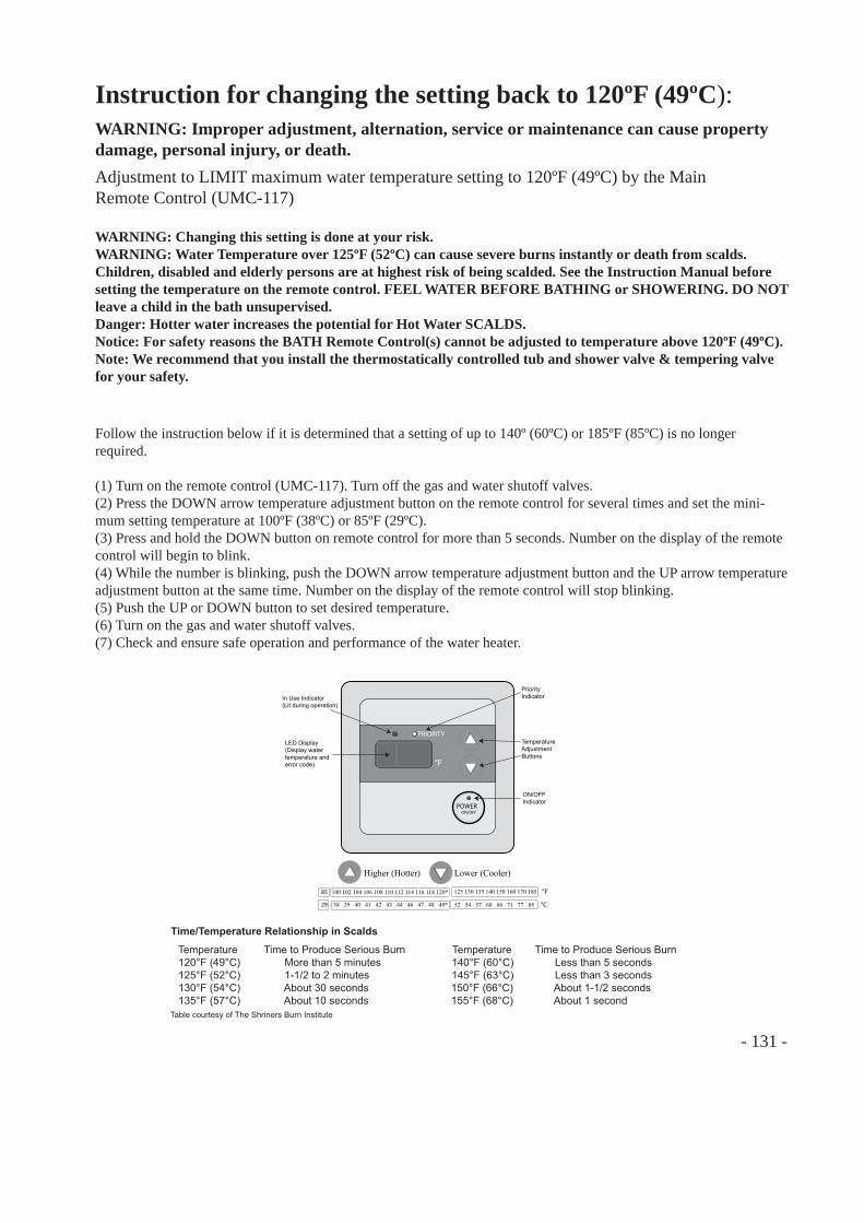
- 131 -
Instruction for changing the setting back to 120ºF (49ºC):WARNING: Improper adjustment, alternation, service or maintenance can cause property damage, personal injury, or death.Adjustment to LIMIT maximum water temperature setting to 120ºF (49ºC) by the Main Remote Control (UMC-117)
Follow the instruction below if it is determined that a setting of up to 140º (60ºC) or 185ºF (85ºC) is no longer required.
(1) Turn on the remote control (UMC-117). Turn off the gas and water shutoff valves.(2) Press the DOWN arrow temperature adjustment button on the remote control for several times and set the mini-mum setting temperature at 100ºF (38ºC) or 85ºF (29ºC).(3) Press and hold the DOWN button on remote control for more than 5 seconds. Number on the display of the remote control will begin to blink.(4) While the number is blinking, push the DOWN arrow temperature adjustment button and the UP arrow temperature adjustment button at the same time. Number on the display of the remote control will stop blinking.(5) Push the UP or DOWN button to set desired temperature.(6) Turn on the gas and water shutoff valves.(7) Check and ensure safe operation and performance of the water heater.
WARNING: Changing this setting is done at your risk.WARNING: Water Temperature over 125ºF (52ºC) can cause severe burns instantly or death from scalds. Children, disabled and elderly persons are at highest risk of being scalded. See the Instruction Manual before setting the temperature on the remote control. FEEL WATER BEFORE BATHING or SHOWERING. DO NOT leave a child in the bath unsupervised.Danger: Hotter water increases the potential for Hot Water SCALDS.Notice: For safety reasons the BATH Remote Control(s) cannot be adjusted to temperature above 120ºF (49ºC).Note: We recommend that you install the thermostatically controlled tub and shower valve & tempering valve for your safety.
°F
PRIORITY
POWERON/OFF
Higher (Hotter) Lower (Cooler)
In Use Indicator(Lit during operation)
LED Display(Display watertemperature and error code)
PriorityIndicator
TemperatureAdjustmentButtons
ON/OFFIndicator
100 102 104 106 108 110 112 114 116 118 120*
38 39 40 41 42 43 44 46 47 48 49*
85
29
125 130 135 140 150 160 170 185 °F
52 54 57 60 66 71 77 85 °C
Temperature Time to Produce Serious Burn Temperature Time to Produce Serious Burn 120°F (49°C) More than 5 minutes 140°F (60°C) Less than 5 seconds 125°F (52°C) 1-1/2 to 2 minutes 145°F (63°C) Less than 3 seconds 130°F (54°C) About 30 seconds 150°F (66°C) About 1-1/2 seconds 135°F (57°C) About 10 seconds 155°F (68°C) About 1 secondTable courtesy of The Shriners Burn Institute
Time/Temperature Relationship in Scalds
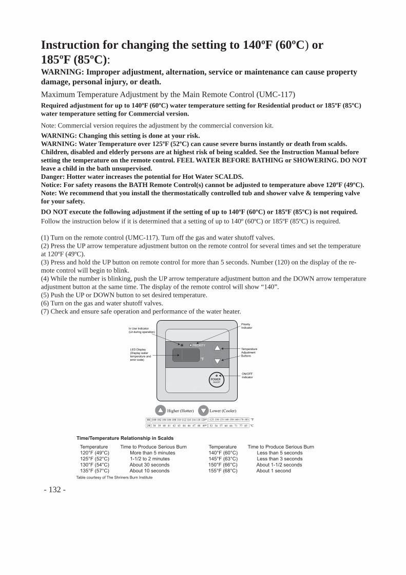
- 132 -
Instruction for changing the setting to 140ºF (60ºC) or185ºF (85ºC):WARNING: Improper adjustment, alternation, service or maintenance can cause property damage, personal injury, or death.Maximum Temperature Adjustment by the Main Remote Control (UMC-117)Required adjustment for up to 140ºF (60ºC) water temperature setting for Residential product or 185ºF (85ºC) water temperature setting for Commercial version.
Follow the instruction below if it is determined that a setting of up to 140º (60ºC) or 185ºF (85ºC) is required.
(1) Turn on the remote control (UMC-117). Turn off the gas and water shutoff valves.(2) Press the UP arrow temperature adjustment button on the remote control for several times and set the temperature at 120ºF (49ºC).(3) Press and hold the UP button on remote control for more than 5 seconds. Number (120) on the display of the re-mote control will begin to blink.(4) While the number is blinking, push the UP arrow temperature adjustment button and the DOWN arrow temperature adjustment button at the same time. The display of the remote control will show “140”.(5) Push the UP or DOWN button to set desired temperature.(6) Turn on the gas and water shutoff valves.(7) Check and ensure safe operation and performance of the water heater.
Note: Commercial version requires the adjustment by the commercial conversion kit.WARNING: Changing this setting is done at your risk.WARNING: Water Temperature over 125ºF (52ºC) can cause severe burns instantly or death from scalds. Children, disabled and elderly persons are at highest risk of being scalded. See the Instruction Manual before setting the temperature on the remote control. FEEL WATER BEFORE BATHING or SHOWERING. DO NOT leave a child in the bath unsupervised.Danger: Hotter water increases the potential for Hot Water SCALDS.Notice: For safety reasons the BATH Remote Control(s) cannot be adjusted to temperature above 120ºF (49ºC).Note: We recommend that you install the thermostatically controlled tub and shower valve & tempering valve for your safety.DO NOT execute the following adjustment if the setting of up to 140ºF (60ºC) or 185ºF (85ºC) is not required.
°F
PRIORITY
POWERON/OFF
Higher (Hotter) Lower (Cooler)
In Use Indicator(Lit during operation)
LED Display(Display watertemperature and error code)
PriorityIndicator
TemperatureAdjustmentButtons
ON/OFFIndicator
100 102 104 106 108 110 112 114 116 118 120*
38 39 40 41 42 43 44 46 47 48 49*
85
29
125 130 135 140 150 160 170 185 °F
52 54 57 60 66 71 77 85 °C
Temperature Time to Produce Serious Burn Temperature Time to Produce Serious Burn 120°F (49°C) More than 5 minutes 140°F (60°C) Less than 5 seconds 125°F (52°C) 1-1/2 to 2 minutes 145°F (63°C) Less than 3 seconds 130°F (54°C) About 30 seconds 150°F (66°C) About 1-1/2 seconds 135°F (57°C) About 10 seconds 155°F (68°C) About 1 secondTable courtesy of The Shriners Burn Institute
Time/Temperature Relationship in Scalds
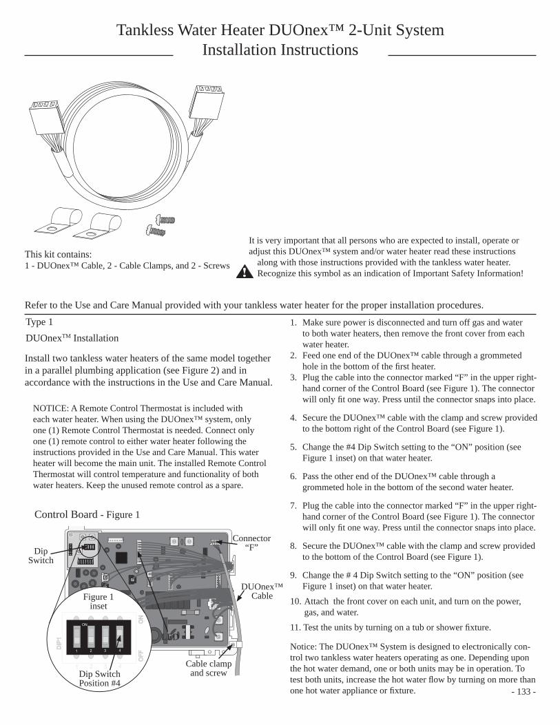
Tankless Water Heater DUOnex™ 2-Unit SystemInstallation Instructions
It is very important that all persons who are expected to install, operate or adjust this DUOnex™ system and/or water heater read these instructions
along with those instructions provided with the tankless water heater. Recognize this symbol as an indication of Important Safety Information!!
Refer to the Use and Care Manual provided with your tankless water heater for the proper installation procedures.
This kit contains: 1 - DUOnex™ Cable, 2 - Cable Clamps, and 2 - Screws
Install two tankless water heaters of the same model together in a parallel plumbing application (see Figure 2) and in accordance with the instructions in the Use and Care Manual.
NOTICE: A Remote Control Thermostat is included with each water heater. When using the DUOnex™ system, only one (1) Remote Control Thermostat is needed. Connect only one (1) remote control to either water heater following the instructions provided in the Use and Care Manual. This water heater will become the main unit. The installed Remote Control Thermostat will control temperature and functionality of both water heaters. Keep the unused remote control as a spare.
1. Make sure power is disconnected and turn off gas and water to both water heaters, then remove the front cover from each water heater.
2. Feed one end of the DUOnex™ cable through a grommeted hole in the bottom of the fi rst heater.
3. Plug the cable into the connector marked “F” in the upper right-hand corner of the Control Board (see Figure 1). The connector will only fi t one way. Press until the connector snaps into place.
4. Secure the DUOnex™ cable with the clamp and screw provided to the bottom right of the Control Board (see Figure 1).
5. Change the #4 Dip Switch setting to the “ON” position (see Figure 1 inset) on that water heater.
6. Pass the other end of the DUOnex™ cable through a grommeted hole in the bottom of the second water heater.
7. Plug the cable into the connector marked “F” in the upper right-hand corner of the Control Board (see Figure 1). The connector will only fi t one way. Press until the connector snaps into place.
8. Secure the DUOnex™ cable with the clamp and screw provided to the bottom of the Control Board (see Figure 1).
9. Change the # 4 Dip Switch setting to the “ON” position (see Figure 1 inset) on that water heater.
10. Attach the front cover on each unit, and turn on the power, gas, and water.
11. Test the units by turning on a tub or shower fi xture.
Notice: The DUOnex™ System is designed to electronically con-trol two tankless water heaters operating as one. Depending upon the hot water demand, one or both units may be in operation. To test both units, increase the hot water fl ow by turning on more than one hot water appliance or fi xture. - 133 -
Control Board - Figure 1
ON
1 2 3 4DIP
1
ON
OFF
1 2 3 4
SW1 SW2
SW3
ON
1 2 3 4DIP
1D
IP1
ON
ON
OFF
OFF
1 2 3 4
Dip Switch
Connector “F”
DUOnex™ Cable
Cable clamp and screw
LED
Dip Switch Position #4
Figure 1 inset
Type 1DUOnexTM Installation
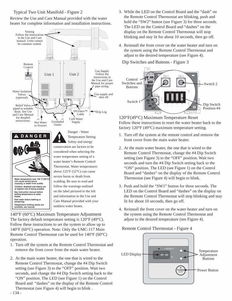
Typical Two Unit Manifold - Figure 2 Review the Use and Care Manual provided with the water heater for complete information and installation instructions.
Danger - Water Temperature Setting Safety and energy
conservation are factors to be considered when selecting the water temperature setting of a water heater’s Remote Control Thermostat. Water temperatures above 125°F (52°C) can cause severe burns or death from scalding. Be sure to read and follow the warnings outlined on the label pictured to the left and information in the Use and Care Manual provided with your tankless water heater.
D A N G E R!
HOT
Water temperature over 125° can cause severe burns instantly or death from scalds.
Children, disabled and elderly areat highest risk of being scalded.
See instruction manual beforesetting temperature at waterheater.Feel water before bathing orshowering.Temperature limiting valves areavailable, see manual.
BURN
F (52°C)
!
140°F (60°C) Maximum Temperature Adjustment The factory default temperature setting is 120°F (49°C). Follow these instructions to set the system to allow up to 140°F (60°C) operation. Note: Only the UMC-117 Main Remote Control Thermostat can be used for 140°F (60°C) operation. 1. Turn off the system at the Remote Control Thermostat and
remove the front cover from the main water heater.
2. At the main water heater, the one that is wired to the Remote Control Thermostat, change the #4 Dip Switch setting (see Figure 3) to the “OFF” position. Wait two seconds, and change the #4 Dip Switch setting back to the “ON” position. The LED (see Figure 1) on the Control Board and “dashes” on the display of the Remote Control Thermostat (see Figure 4) will begin to blink .
Dip Switches and Buttons - Figure 3
120°F(49°C) Maximum Temperature Reset Follow these instructions to reset the water heater back to the factory 120°F (49°C) maximum temperature setting.
1. Turn off the system at the remote control and remove the front cover from the main water heater.
2. At the main water heater, the one that is wired to the Remote Control Thermostat, change the #4 Dip Switch setting (see Figure 3) to the “OFF” position. Wait two seconds and turn the #4 Dip Switch setting back to the “ON” position. The LED (see Figure 1) on the Control Board and “dashes” on the display of the Remote Control Thermostat (see Figure 4) will begin to blink.
3. Push and hold the “SW1” button for three seconds. The LED on the Control Board and “dashes” on the display on the Remote Control Thermostat will stop blinking and stay lit for about 10 seconds, then go off.
4. Reinstall the front cover on the water heater and turn on the system using the Remote Control Thermostat and adjust to the desired temperature (see Figure 4).
Remote Control Thermostat - Figure 4
°F
PRIORITY
POWERON/OFF
LED DisplayTemperature Adjustment
Buttons
Power Button
ON
1 2 3 4 DIP
1
ON
O
FF
1 2 3 4
SW1 SW2
SW3
ON
1 2 3 4DIP
1D
IP1
ON
ON
OFF
OFF
1 2 3 4
SW 1 SW 2
SW 3
Control Switches and
Buttons
Switch 1
Switch 2
Dip Switch Position #4
Vent Termination
°F
PRIORITY
POWERON/OFF
Venting Follow the instructions
in the Use and Care manual. Units cannot be common vented.
Remote Control
Water Isolation Valves
(optional)
Relief Valve piped to suitable drain. See Use
and Care Manual for detailed instructions. Hot Water
to fi xturesGrounded
Outlet
Cold Water Supply
DUOnex™ Cable
Drip Leg
Gas supply and shut off
Gas SupplyFollow the
instructions in the Use and Care Manual for proper
pipe sizing.
Unit 2Unit 1
3. While the LED on the Control Board and the “dash” on the Remote Control Thermostat are blinking, push and hold the “SW2” button (see Figure 3) for three seconds. The LED on the Control Board and “dashes” on the display on the Remote Control Thermostat will stop blinking and stay lit for about 10 seconds, then go off.
4. Reinstall the front cover on the water heater and turn on the system using the Remote Control Thermostat and adjust to the desired temperature (see Figure 4).
- 134 -
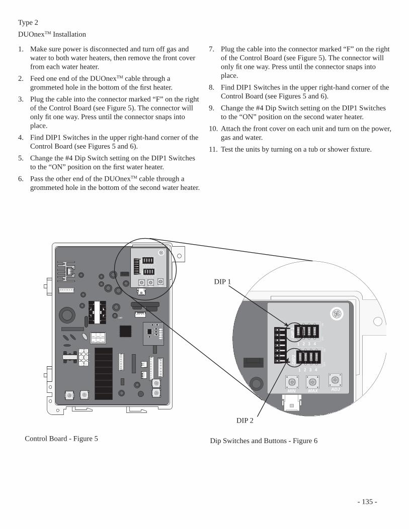
1. Make sure power is disconnected and turn off gas and water to both water heaters, then remove the front cover from each water heater.
2. Feed one end of the DUOnexTM cable through a grommeted hole in the bottom of the fi rst heater.
3. Plug the cable into the connector marked “F” on the right of the Control Board (see Figure 5). The connector will only fi t one way. Press until the connector snaps into place.
4. Find DIP1 Switches in the upper right-hand corner of the Control Board (see Figures 5 and 6).
5. Change the #4 Dip Switch setting on the DIP1 Switches to the “ON” position on the fi rst water heater.
6. Pass the other end of the DUOnexTM cable through a grommeted hole in the bottom of the second water heater.
7. Plug the cable into the connector marked “F” on the right of the Control Board (see Figure 5). The connector will only fi t one way. Press until the connector snaps into place.
8. Find DIP1 Switches in the upper right-hand corner of the Control Board (see Figures 5 and 6).
9. Change the #4 Dip Switch setting on the DIP1 Switches to the “ON” position on the second water heater.
10. Attach the front cover on each unit and turn on the power, gas and water.
11. Test the units by turning on a tub or shower fi xture.
ON
1 2 3 4
ON
OFF
ON
1 2 3 4
ON
OFF
1 2 3 4
1 2 3 4
DIP
2D
IP1
MIN MAX ADJ
LED
ON
1 2 3 4
ON
OFF
ON
1 2 3 4
ON
OFF
1 2 3 4
1 2 3 4
DIP
2D
IP 1
MIN MAX ADJ
Dip Switches and Buttons - Figure 6 Control Board - Figure 5
DIP 1
DIP 2
Type 2DUOnexTM Installation
- 135 -
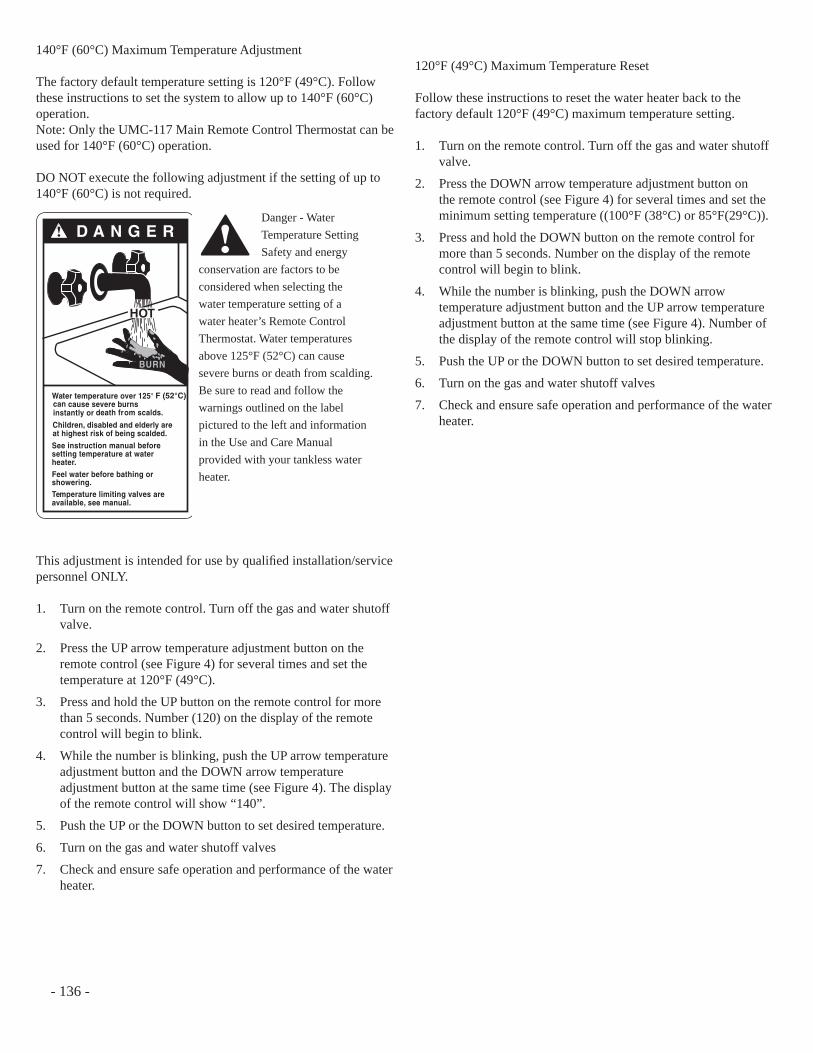
140°F (60°C) Maximum Temperature Adjustment
The factory default temperature setting is 120°F (49°C). Follow these instructions to set the system to allow up to 140°F (60°C) operation. Note: Only the UMC-117 Main Remote Control Thermostat can be used for 140°F (60°C) operation.
DO NOT execute the following adjustment if the setting of up to 140°F (60°C) is not required.
This adjustment is intended for use by qualifi ed installation/service personnel ONLY. 1. Turn on the remote control. Turn off the gas and water shutoff
valve.
2. Press the UP arrow temperature adjustment button on the remote control (see Figure 4) for several times and set the temperature at 120°F (49°C).
3. Press and hold the UP button on the remote control for more than 5 seconds. Number (120) on the display of the remote control will begin to blink.
4. While the number is blinking, push the UP arrow temperature adjustment button and the DOWN arrow temperature adjustment button at the same time (see Figure 4). The display of the remote control will show “140”.
5. Push the UP or the DOWN button to set desired temperature.
6. Turn on the gas and water shutoff valves
7. Check and ensure safe operation and performance of the water heater.
120°F (49°C) Maximum Temperature Reset
Follow these instructions to reset the water heater back to the factory default 120°F (49°C) maximum temperature setting. 1. Turn on the remote control. Turn off the gas and water shutoff
valve.
2. Press the DOWN arrow temperature adjustment button on the remote control (see Figure 4) for several times and set the minimum setting temperature ((100°F (38°C) or 85°F(29°C)).
3. Press and hold the DOWN button on the remote control for more than 5 seconds. Number on the display of the remote control will begin to blink.
4. While the number is blinking, push the DOWN arrow temperature adjustment button and the UP arrow temperature adjustment button at the same time (see Figure 4). Number of the display of the remote control will stop blinking.
5. Push the UP or the DOWN button to set desired temperature.
6. Turn on the gas and water shutoff valves
7. Check and ensure safe operation and performance of the water heater.
Danger - Water Temperature Setting Safety and energy
conservation are factors to be considered when selecting the water temperature setting of a water heater’s Remote Control Thermostat. Water temperatures above 125°F (52°C) can cause severe burns or death from scalding. Be sure to read and follow the warnings outlined on the label pictured to the left and information in the Use and Care Manual provided with your tankless water heater.
D A N G E R!
HOT
Water temperature over 125° can cause severe burns instantly or death from scalds.
Children, disabled and elderly areat highest risk of being scalded.
See instruction manual beforesetting temperature at waterheater.Feel water before bathing orshowering.Temperature limiting valves areavailable, see manual.
BURN
F (52°C)
!
- 136 -
1
MIC-185 Manifold ControllerOperation and Installation Manual
SAFETY PRECAUTIONS● Read these instructions and the water heater instruction manual entirely before installing or
operating the manifold controller and the water heater.
● Use this manifold controller only for its intended purpose as described in these instructions.
● Be sure your water heater and the manifold controller are properly installed in accordance with
local codes and the provided installation instructions.
● Do not attempt to repair or replace any parts. All servicing should be referred to a qualifi ed
technician.
● Read and follow all instructions. Save this instruction for future reference.
Table of Contents
Safety Information
Operation Instructions
Trouble Shooting and Diagnosis
Instructions for the Installer
Extended Communications Board
High Temperature Operation
- 137 -
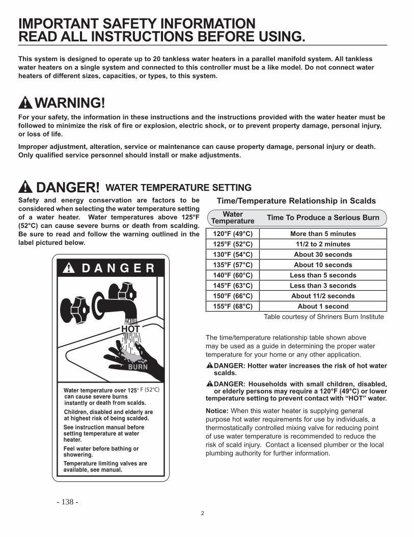
2
IMPORTANT SAFETY INFORMATIONREAD ALL INSTRUCTIONS BEFORE USING.
Safety and energy conservation are factors to be considered when selecting the water temperature setting of a water heater. Water temperatures above 125°F (52°C) can cause severe burns or death from scalding. Be sure to read and follow the warning outlined in the label pictured below.
WATER TEMPERATURE SETTING
For your safety, the information in these instructions and the instructions provided with the water heater must be followed to minimize the risk of fire or explosion, electric shock, or to prevent property damage, personal injury, or loss of life.
Improper adjustment, alteration, service or maintenance can cause property damage, personal injury or death. Only qualified service personnel should install or make adjustments.
Water Temperature Time To Produce a Serious Burn
120°F (49°C) More than 5 minutes125°F (52°C) 11/2 to 2 minutes130°F (54°C) About 30 seconds135°F (57°C) About 10 seconds140°F (60°C) Less than 5 seconds145°F (63°C) Less than 3 seconds150°F (66°C) About 11/2 seconds155°F (68°C) About 1 second
Table courtesy of Shriners Burn Institute
Time/Temperature Relationship in Scalds
D A N G E R!
HOT
Water temperature over 125° can cause severe burns instantly or death from scalds.
Children, disabled and elderly areat highest risk of being scalded.
See instruction manual beforesetting temperature at waterheater.Feel water before bathing orshowering.Temperature limiting valves areavailable, see manual.
BURN
F (52°C)
The time/temperature relationship table shown above may be used as a guide in determining the proper water temperature for your home or any other application. ! DANGER: Hotter water increases the risk of hot water
scalds.! DANGER: Households with small children, disabled,
or elderly persons may require a 120°F (49°C) or lower temperature setting to prevent contact with “HOT” water.
Notice: When this water heater is supplying general purpose hot water requirements for use by individuals, a thermostatically controlled mixing valve for reducing point of use water temperature is recommended to reduce the risk of scald injury. Contact a licensed plumber or the local plumbing authority for further information.
WARNING!!
! DANGER!
This system is designed to operate up to 20 tankless water heaters in a parallel manifold system. All tankless water heaters on a single system and connected to this controller must be a like model. Do not connect water heaters of different sizes, capacities, or types, to this system.
- 138 -
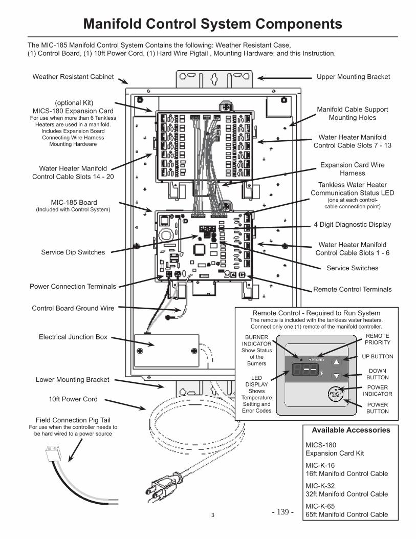
3
Manifold Control System Components
(optional Kit)MICS-180 Expansion Card
For use when more than 6 Tankless Heaters are used in a manifold.
Includes Expansion BoardConnecting Wire Harness
Mounting Hardware
MIC-185 Board(Included with Control System)
The MIC-185 Manifold Control System Contains the following: Weather Resistant Case, (1) Control Board, (1) 10ft Power Cord, (1) Hard Wire Pigtail , Mounting Hardware, and this Instruction.
Electrical Junction Box
10ft Power Cord
Field Connection Pig TailFor use when the controller needs to
be hard wired to a power source
Weather Resistant Cabinet Upper Mounting Bracket
Expansion Card WireHarness
Water Heater Manifold Control Cable Slots 7 - 13
Water Heater Manifold Control Cable Slots 14 - 20
Water Heater Manifold Control Cable Slots 1 - 6
Manifold Cable Support Mounting Holes
4 Digit Diagnostic Display
Service Dip Switches
Service Switches
Remote Control Terminals
Available Accessories
MICS-180 Expansion Card Kit MIC-K-16 16ft Manifold Control Cable MIC-K-32 32ft Manifold Control Cable MIC-K-65 65ft Manifold Control Cable
Lower Mounting Bracket
Remote Control - Required to Run SystemThe remote is included with the tankless water heaters. Connect only one (1) remote of the manifold controller.
REMOTEPRIORITY
BURNERINDICATORShow Status
of the Burners
LED DISPLAY
Shows Temperature Setting and Error Codes
UP BUTTON
DOWN BUTTON
POWER BUTTON
POWER INDICATOR
Tankless Water Heater Communication Status LED
(one at each control- cable connection point)
Power Connection Terminals
Control Board Ground Wire
- 139 -
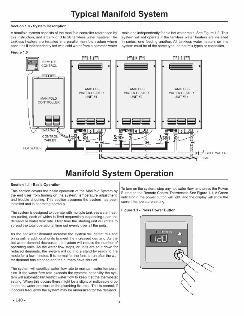
4
Typical Manifold System
A manifold system consists of the manifold controller referenced by this instruction, and a bank or 3 to 20 tankless water heaters. The tankless heaters are installed in a parallel manifold system where each unit if independently fed with cold water from a common water
main and independently feed a hot water main. See Figure 1.0. This system will not operate if the tankless water heaters are installed in series, one feeding another. All tankless water heaters on this system must be of the same type, do not mix types or capacities.
Section 1.1 - Basic Operation
This section covers the basic operation of the Manifold System by the end user from turning on the system, temperature adjustment, and trouble shooting. This section assumes the system has been installed and is operating normally.
The system is designed to operate with multiple tankless water heat-ers (units), each of which is fi red sequentially depending upon the demand or water fl ow rate. Over time the starting unit will rotate to spread the total operational time out evenly over all the units.
As the hot water demand increase the system will detect this and bring online additional units to meet the increased demand. As the hot water demand decreases the system will reduce the number of operating units. As the water fl ow stops, or units are shut down for reduced demands, the system will go into a stand by ready to fi re mode for a few minutes. It is normal for the fans to run after the wa-ter demand has stopped and the burners have shut off.
The system will sacrifi ce water fl ow rate to maintain water tempera-ture. If the water fl ow rate exceeds the systems capability the sys-tem will automatically restrict water fl ow to keep it at the thermostat setting. When this occurs there might be a slight or noticeable drop in the hot water pressure at the plumbing fi xtures. This is normal, if it occurs frequently the system may be undersized for the demand.
Section 1.0 - System Description
Figure 1.0
HOT WATERCOLD WATER
GAS
CONTROL CABLES
MANIFOLD CONTROLLER
REMOTE CONTROL
TANKLESS WATER HEATER
UNIT #1
TANKLESS WATER HEATER
UNIT #2
TANKLESS WATER HEATER
UNIT #3+
Manifold System OperationTo turn on the system, stop any hot water fl ow, and press the Power Button on the Remote Control Thermostat. See Figure 1.1. A Green indicator in the power button will light, and the display will show the current temperature setting.
Figure 1.1 - Press Power Button
- 140 -
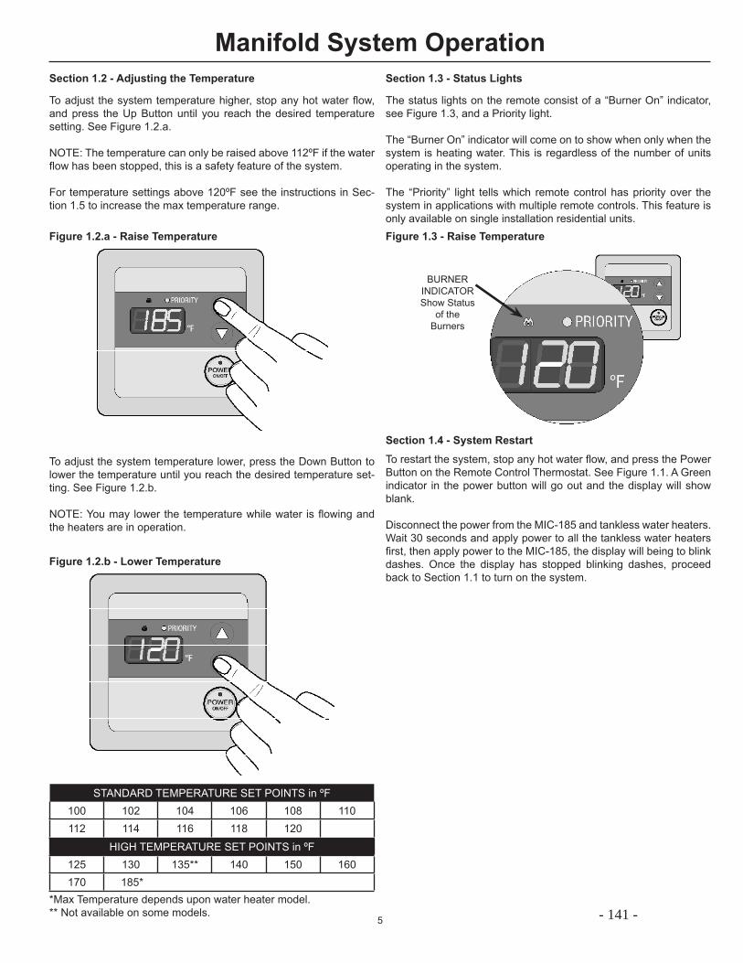
5
Section 1.2 - Adjusting the Temperature
To adjust the system temperature higher, stop any hot water fl ow, and press the Up Button until you reach the desired temperature setting. See Figure 1.2.a.
NOTE: The temperature can only be raised above 112ºF if the water fl ow has been stopped, this is a safety feature of the system.
For temperature settings above 120ºF see the instructions in Sec-tion 1.5 to increase the max temperature range.
Manifold System Operation
To adjust the system temperature lower, press the Down Button to lower the temperature until you reach the desired temperature set-ting. See Figure 1.2.b.
NOTE: You may lower the temperature while water is fl owing and the heaters are in operation.
Figure 1.2.a - Raise Temperature
Figure 1.2.b - Lower Temperature
STANDARD TEMPERATURE SET POINTS in ºF100 102 104 106 108 110112 114 116 118 120
HIGH TEMPERATURE SET POINTS in ºF125 130 135** 140 150 160170 185*
*Max Temperature depends upon water heater model. ** Not available on some models.
Section 1.3 - Status Lights
The status lights on the remote consist of a “Burner On” indicator, see Figure 1.3, and a Priority light.
The “Burner On” indicator will come on to show when only when the system is heating water. This is regardless of the number of units operating in the system.
The “Priority” light tells which remote control has priority over the system in applications with multiple remote controls. This feature is only available on single installation residential units.Figure 1.3 - Raise Temperature
BURNERINDICATORShow Status
of the Burners
Section 1.4 - System RestartTo restart the system, stop any hot water fl ow, and press the Power Button on the Remote Control Thermostat. See Figure 1.1. A Green indicator in the power button will go out and the display will show blank.
Disconnect the power from the MIC-185 and tankless water heaters. Wait 30 seconds and apply power to all the tankless water heaters fi rst, then apply power to the MIC-185, the display will being to blink dashes. Once the display has stopped blinking dashes, proceed back to Section 1.1 to turn on the system.
- 141 -
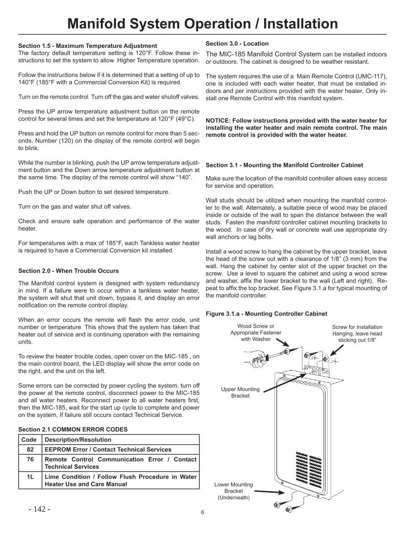
6
The Manifold control system is designed with system redundancy in mind. If a failure were to occur within a tankless water heater, the system will shut that unit down, bypass it, and display an error notifi cation on the remote control display.
When an error occurs the remote will fl ash the error code, unit number or temperature. This shows that the system has taken that heater out of service and is continuing operation with the remaining units.
To review the heater trouble codes, open cover on the MIC-185 , on the main control board, the LED display will show the error code on the right, and the unit on the left.
Some errors can be corrected by power cycling the system, turn off the power at the remote control, disconnect power to the MIC-185 and all water heaters. Reconnect power to all water heaters fi rst, then the MIC-185, wait for the start up cycle to complete and power on the system, If failure still occurs contact Technical Service.
Section 2.1 COMMON ERROR CODESCode Description/Resolution
82 EEPROM Error / Contact Technical Services76 Remote Control Communication Error / Contact
Technical Services1L Lime Condition / Follow Flush Procedure in Water
Heater Use and Care Manual
Manifold System Operation / Installation
Section 2.0 - When Trouble Occurs
NOTICE: Follow instructions provided with the water heater for installing the water heater and main remote control. The main remote control is provided with the water heater.
Section 3.0 - Location
The MIC-185 Manifold Control System can be installed indoors or outdoors. The cabinet is designed to be weather resistant.
The system requires the use of a Main Remote Control (UMC-117), one is included with each water heater, that must be installed in-doors and per instructions provided with the water heater. Only in-stall one Remote Control with this manifold system.
Section 3.1 - Mounting the Manifold Controller Cabinet
Make sure the location of the manifold controller allows easy access for service and operation.
Wall studs should be utilized when mounting the manifold control-ler to the wall. Alternately, a suitable piece of wood may be placed inside or outside of the wall to span the distance between the wall studs. Fasten the manifold controller cabinet mounting brackets to the wood. In case of dry wall or concrete wall use appropriate dry wall anchors or lag bolts.
Install a wood screw to hang the cabinet by the upper bracket, leave the head of the screw out with a clearance of 1/8” (3 mm) from the wall. Hang the cabinet by center slot of the upper bracket on the screw. Use a level to square the cabinet and using a wood screw and washer, affi x the lower bracket to the wall (Left and right). Re-peat to affi x the top bracket. See Figure 3.1.a for typical mounting of the manifold controller.
Figure 3.1.a - Mounting Controller Cabinet
Screw for Installation Hanging, leave head
sticking out 1/8”
Wood Screw or Appropriate Fastener
with Washer
Upper Mounting Bracket
Lower Mounting Bracket
(Underneath)
Section 1.5 - Maximum Temperature AdjustmentThe factory default temperature setting is 120°F. Follow these in-structions to set the system to allow Higher Temperature operation.
Follow the instructions below if it is determined that a setting of up to 140°F (185°F with a Commercial Conversion Kit) is required.
Turn on the remote control. Turn off the gas and water shutoff valves.
Press the UP arrow temperature adjustment button on the remote control for several times and set the temperature at 120°F (49°C).
Press and hold the UP button on remote control for more than 5 sec-onds. Number (120) on the display of the remote control will begin to blink.
While the number is blinking, push the UP arrow temperature adjust-ment button and the Down arrow temperature adjustment button at the same time. The display of the remote control will show “140”.
Push the UP or Down button to set desired temperature.
Turn on the gas and water shut off valves.
Check and ensure safe operation and performance of the water heater.
For temperatures with a max of 185°F, each Tankless water heater is required to have a Commercial Conversion kit installed.
- 142 -
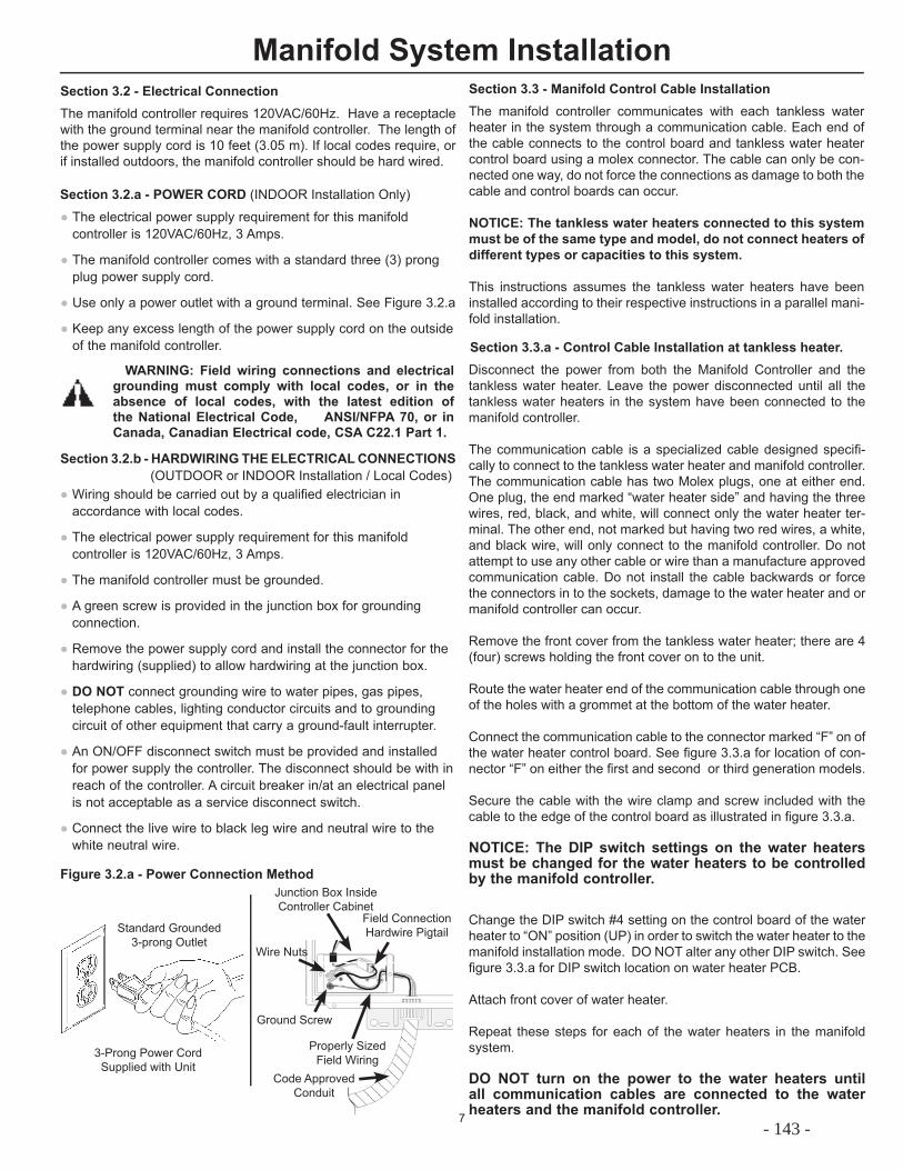
7
WARNING: Field wiring connections and electrical grounding must comply with local codes, or in the absence of local codes, with the latest edition of the National Electrical Code, ANSI/NFPA 70, or in Canada, Canadian Electrical code, CSA C22.1 Part 1.
Manifold System InstallationSection 3.2 - Electrical ConnectionThe manifold controller requires 120VAC/60Hz. Have a receptacle with the ground terminal near the manifold controller. The length of the power supply cord is 10 feet (3.05 m). If local codes require, or if installed outdoors, the manifold controller should be hard wired.
● The electrical power supply requirement for this manifold controller is 120VAC/60Hz, 3 Amps.
● The manifold controller comes with a standard three (3) prong plug power supply cord.
● Use only a power outlet with a ground terminal. See Figure 3.2.a
● Keep any excess length of the power supply cord on the outside of the manifold controller.
● Wiring should be carried out by a qualified electrician in accordance with local codes.
● The electrical power supply requirement for this manifold controller is 120VAC/60Hz, 3 Amps.
● The manifold controller must be grounded.
● A green screw is provided in the junction box for grounding connection.
● Remove the power supply cord and install the connector for the hardwiring (supplied) to allow hardwiring at the junction box.
● DO NOT connect grounding wire to water pipes, gas pipes, telephone cables, lighting conductor circuits and to grounding circuit of other equipment that carry a ground-fault interrupter.
● An ON/OFF disconnect switch must be provided and installed for power supply the controller. The disconnect should be with in reach of the controller. A circuit breaker in/at an electrical panel is not acceptable as a service disconnect switch.
● Connect the live wire to black leg wire and neutral wire to the white neutral wire.
Section 3.2.a - POWER CORD (INDOOR Installation Only)
Section 3.2.b - HARDWIRING THE ELECTRICAL CONNECTIONS (OUTDOOR or INDOOR Installation / Local Codes)
Figure 3.2.a - Power Connection Method
Standard Grounded 3-prong Outlet
3-Prong Power CordSupplied with Unit
Junction Box Inside Controller Cabinet
Code Approved Conduit
Field Connection Hardwire Pigtail
Ground Screw
Properly Sized Field Wiring
Wire Nuts
Section 3.3 - Manifold Control Cable InstallationThe manifold controller communicates with each tankless water heater in the system through a communication cable. Each end of the cable connects to the control board and tankless water heater control board using a molex connector. The cable can only be con-nected one way, do not force the connections as damage to both the cable and control boards can occur.
NOTICE: The tankless water heaters connected to this system must be of the same type and model, do not connect heaters of different types or capacities to this system.
This instructions assumes the tankless water heaters have been installed according to their respective instructions in a parallel mani-fold installation.
Disconnect the power from both the Manifold Controller and the tankless water heater. Leave the power disconnected until all the tankless water heaters in the system have been connected to the manifold controller.
The communication cable is a specialized cable designed specifi -cally to connect to the tankless water heater and manifold controller. The communication cable has two Molex plugs, one at either end. One plug, the end marked “water heater side” and having the three wires, red, black, and white, will connect only the water heater ter-minal. The other end, not marked but having two red wires, a white, and black wire, will only connect to the manifold controller. Do not attempt to use any other cable or wire than a manufacture approved communication cable. Do not install the cable backwards or force the connectors in to the sockets, damage to the water heater and or manifold controller can occur.
Remove the front cover from the tankless water heater; there are 4 (four) screws holding the front cover on to the unit.
Route the water heater end of the communication cable through one of the holes with a grommet at the bottom of the water heater.
Connect the communication cable to the connector marked “F” on of the water heater control board. See fi gure 3.3.a for location of con-nector “F” on either the fi rst and second or third generation models.
Secure the cable with the wire clamp and screw included with the cable to the edge of the control board as illustrated in fi gure 3.3.a.
NOTICE: The DIP switch settings on the water heaters must be changed for the water heaters to be controlled by the manifold controller.
Change the DIP switch #4 setting on the control board of the water heater to “ON” position (UP) in order to switch the water heater to the manifold installation mode. DO NOT alter any other DIP switch. See fi gure 3.3.a for DIP switch location on water heater PCB.
Attach front cover of water heater.
Repeat these steps for each of the water heaters in the manifold system.
DO NOT turn on the power to the water heaters until all communication cables are connected to the water heaters and the manifold controller.
Section 3.3.a - Control Cable Installation at tankless heater.
- 143 -
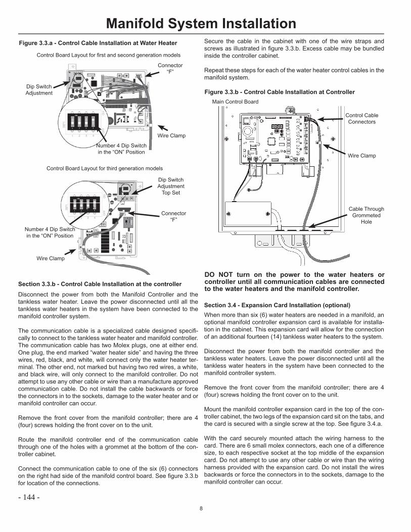
8
Manifold System InstallationFigure 3.3.a - Control Cable Installation at Water Heater
Number 4 Dip Switch in the “ON” Position
Control Board Layout for fi rst and second generation models
Control Board Layout for third generation models
Dip SwitchAdjustment
Connector“F”
Wire Clamp
Number 4 Dip Switch in the “ON” Position
Dip SwitchAdjustment
Top Set
Connector“F”
Wire Clamp
Disconnect the power from both the Manifold Controller and the tankless water heater. Leave the power disconnected until all the tankless water heaters in the system have been connected to the manifold controller system.
The communication cable is a specialized cable designed specifi -cally to connect to the tankless water heater and manifold controller. The communication cable has two Molex plugs, one at either end. One plug, the end marked “water heater side” and having the three wires, red, black, and white, will connect only the water heater ter-minal. The other end, not marked but having two red wires, a white, and black wire, will only connect to the manifold controller. Do not attempt to use any other cable or wire than a manufacture approved communication cable. Do not install the cable backwards or force the connectors in to the sockets, damage to the water heater and or manifold controller can occur.
Remove the front cover from the manifold controller; there are 4 (four) screws holding the front cover on to the unit.
Route the manifold controller end of the communication cable through one of the holes with a grommet at the bottom of the con-troller cabinet.
Connect the communication cable to one of the six (6) connectors on the right had side of the manifold control board. See fi gure 3.3.b for location of the connections.
Section 3.3.b - Control Cable Installation at the controller
Figure 3.3.b - Control Cable Installation at Controller
Control CableConnectors
DO NOT turn on the power to the water heaters or controller until all communication cables are connected to the water heaters and the manifold controller.
Wire Clamp
Cable ThroughGrommeted
Hole
Section 3.4 - Expansion Card Installation (optional)When more than six (6) water heaters are needed in a manifold, an optional manifold controller expansion card is available for installa-tion in the cabinet. This expansion card will allow for the connection of an additional fourteen (14) tankless water heaters to the system.
Disconnect the power from both the manifold controller and the tankless water heaters. Leave the power disconnected until all the tankless water heaters in the system have been connected to the manifold controller system.
Remove the front cover from the manifold controller; there are 4 (four) screws holding the front cover on to the unit.
Mount the manifold controller expansion card in the top of the con-troller cabinet, the two legs of the expansion card sit on the tabs, and the card is secured with a single screw at the top. See fi gure 3.4.a.
With the card securely mounted attach the wiring harness to the card. There are 6 small molex connectors, each one of a difference size, to each respective socket at the top middle of the expansion card. Do not attempt to use any other cable or wire than the wiring harness provided with the expansion card. Do not install the wires backwards or force the connectors in to the sockets, damage to the manifold controller can occur.
Main Control Board
Secure the cable in the cabinet with one of the wire straps and screws as illustrated in fi gure 3.3.b. Excess cable may be bundled inside the controller cabinet.
Repeat these steps for each of the water heater control cables in the manifold system.
- 144 -
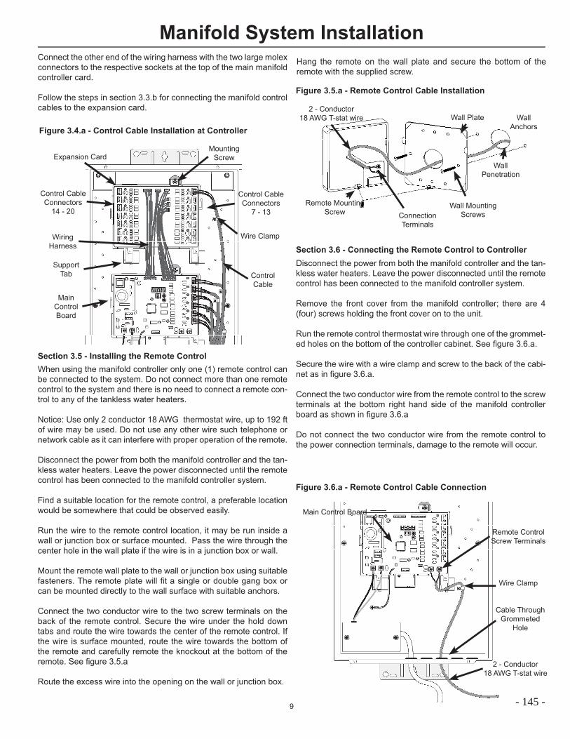
9
Manifold System Installation
Figure 3.4.a - Control Cable Installation at Controller
Control CableConnectors
7 - 13
Wire Clamp
Control CableConnectors
14 - 20
ControlCable
Expansion Card
WiringHarness
MainControlBoard
MountingScrew
SupportTab
Connect the other end of the wiring harness with the two large molex connectors to the respective sockets at the top of the main manifold controller card.
Follow the steps in section 3.3.b for connecting the manifold control cables to the expansion card.
Section 3.5 - Installing the Remote ControlWhen using the manifold controller only one (1) remote control can be connected to the system. Do not connect more than one remote control to the system and there is no need to connect a remote con-trol to any of the tankless water heaters.
Notice: Use only 2 conductor 18 AWG thermostat wire, up to 192 ft of wire may be used. Do not use any other wire such telephone or network cable as it can interfere with proper operation of the remote.
Disconnect the power from both the manifold controller and the tan-kless water heaters. Leave the power disconnected until the remote control has been connected to the manifold controller system.
Find a suitable location for the remote control, a preferable location would be somewhere that could be observed easily.
Run the wire to the remote control location, it may be run inside a wall or junction box or surface mounted. Pass the wire through the center hole in the wall plate if the wire is in a junction box or wall.
Mount the remote wall plate to the wall or junction box using suitable fasteners. The remote plate will fi t a single or double gang box or can be mounted directly to the wall surface with suitable anchors.
Connect the two conductor wire to the two screw terminals on the back of the remote control. Secure the wire under the hold down tabs and route the wire towards the center of the remote control. If the wire is surface mounted, route the wire towards the bottom of the remote and carefully remote the knockout at the bottom of the remote. See fi gure 3.5.a
Route the excess wire into the opening on the wall or junction box.
Figure 3.5.a - Remote Control Cable Installation
ConnectionTerminals
Remote Mounting Screw
Wall Plate2 - Conductor
18 AWG T-stat wire
Wall Mounting Screws
Wall Penetration
WallAnchors
Hang the remote on the wall plate and secure the bottom of the remote with the supplied screw.
Section 3.6 - Connecting the Remote Control to ControllerDisconnect the power from both the manifold controller and the tan-kless water heaters. Leave the power disconnected until the remote control has been connected to the manifold controller system.
Remove the front cover from the manifold controller; there are 4 (four) screws holding the front cover on to the unit.
Run the remote control thermostat wire through one of the grommet-ed holes on the bottom of the controller cabinet. See fi gure 3.6.a.
Secure the wire with a wire clamp and screw to the back of the cabi-net as in fi gure 3.6.a.
Connect the two conductor wire from the remote control to the screw terminals at the bottom right hand side of the manifold controller board as shown in fi gure 3.6.a
Do not connect the two conductor wire from the remote control to the power connection terminals, damage to the remote will occur.
Figure 3.6.a - Remote Control Cable Connection
2 - Conductor18 AWG T-stat wire
Wire Clamp
Cable ThroughGrommeted
Hole
Main Control Board
Remote ControlScrew Terminals
- 145 -
10
Manifold System InstallationSection 4 - System Start UpOnce the tankless water heaters have been setup and remote con-trol has been installed as instructed in Section 3, you may begin the startup process.
If the manifold control system has been previously powered up, turn off the power at the remote control fi rst, then unplug or disconnect the power supply from the manifold controller. If power is discon-nected before the remote is turned off the system will retain any previous errors and system status. Turning the remote off prior to disconnecting the power supply will reset the system status.
Remove the front cover from the manifold controller; there are 4 (four) screws holding the front cover on to the unit.
Shutoff all water fl ow from the system.
Turn on the gas supply to the tankless water heaters.
Plug in or turn on the power supply to all the tankless water heaters.
Wait 30 seconds after the last unit has had the power turned on.
Plug in or turn on the power supply to the Manifold Controller
The remote control and diagnostic display on the main control board inside the manifold control cabinet unit will begin to blink “dashes”, see fi gure on page 3. The dashes will appear while the system is synchronizing with the tankless water heaters. Depending upon the number of tankless water heaters connected to the system, this synchronization can take up to 3 minutes. Once the system has syn-chronized the remote control and diagnostic display will go blank.
An LED indicator will light up “solid” next to each connector where a control cable is plugged in to the main control board and/or expan-sion card. If the LED indicator next to a connector begins to blink or does not light then an error has occurred with the communication to the water heater. Check the diagnostic display for an error code and recheck all connections. If an error occurs then the entire start up process will need to be repeated.
Press the power button on the remote control, it should now display the water temperature.
Turn on or start with a low hot water demand or fl ow. The burner on indicator light on the remote should come on once the system has started to fi re and the diagnostic display on the control board will show “on”.
Increase the hot water demand or fl ow to turn on additional units in the system. Continue to increase the fl ow rate until all the units in the system are running.
- 146 -
1
MIC-6 Manifold ControllerOperation and Installation Manual
SAFETY PRECAUTIONS● Read these instructions and the water heater instruction manual entirely before installing or
operating the manifold controller and the water heater.
● Use this manifold controller only for its intended purpose as described in these instructions.
● Be sure your water heater and the manifold controller are properly installed in accordance with
local codes and the provided installation instructions.
● Do not attempt to repair or replace any parts. All servicing should be referred to a qualifi ed
technician.
● Read and follow all instructions. Save this instruction for future reference.
Table of Contents
Safety Information
Operation Instructions
Instructions for the Installer
High Temperature Operation
- 147 -
This system is designed to operate up to 6 tankless water heaters in a parallel manifold system. All tankless water heaters on a single system and connected to this controller must be a like model. Do not connect water heaters of different sizes, capacities, or types, to this system.
Do not attempt to install this controller in a model other than what is listed on the cover of this instruction.
2
IMPORTANT SAFETY INFORMATIONREAD ALL INSTRUCTIONS BEFORE USING.
Safety and energy conservation are factors to be considered when selecting the water temperature setting of a water heater. Water temperatures above 125°F (52°C) can cause severe burns or death from scalding. Be sure to read and follow the warning outlined in the label pictured below.
WATER TEMPERATURE SETTING
For your safety, the information in these instructions and the instructions provided with the water heater must be followed to minimize the risk of fire or explosion, electric shock, or to prevent property damage, personal injury, or loss of life.
Improper adjustment, alteration, service or maintenance can cause property damage, personal injury or death. Only qualified service personnel should install or make adjustments.
Water Temperature Time To Produce a Serious Burn
120°F (49°C) More than 5 minutes125°F (52°C) 11/2 to 2 minutes130°F (54°C) About 30 seconds135°F (57°C) About 10 seconds140°F (60°C) Less than 5 seconds145°F (63°C) Less than 3 seconds150°F (66°C) About 11/2 seconds155°F (68°C) About 1 second
Table courtesy of Shriners Burn Institute
Time/Temperature Relationship in Scalds
D A N G E R!
HOT
Water temperature over 125° can cause severe burns instantly or death from scalds.
Children, disabled and elderly areat highest risk of being scalded.
See instruction manual beforesetting temperature at waterheater.Feel water before bathing orshowering.Temperature limiting valves areavailable, see manual.
BURN
F (52°C)
The time/temperature relationship table shown above may be used as a guide in determining the proper water temperature for your home or any other application. ! DANGER: Hotter water increases the risk of hot water
scalds.! DANGER: Households with small children, disabled,
or elderly persons may require a 120°F (49°C) or lower temperature setting to prevent contact with “HOT” water.
Notice: When this water heater is supplying general purpose hot water requirements for use by individuals, a thermostatically controlled mixing valve for reducing point of use water temperature is recommended to reduce the risk of scald injury. Contact a licensed plumber or the local plumbing authority for further information.
WARNING!!
! DANGER!
This system is designed to operate up to 6 tankless water heaters in a parallel manifold system. All tankless water heaters on a single system and connected to this controller must be a like model. Do not connect water heaters of different sizes, capacities, or types, to this system.
- 148 -
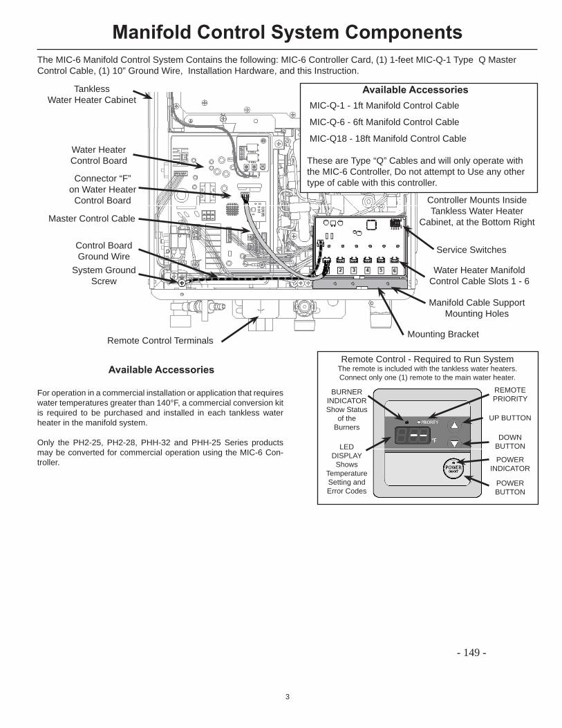
3
Manifold Control System Components
Controller Mounts InsideTankless Water Heater
Cabinet, at the Bottom Right
The MIC-6 Manifold Control System Contains the following: MIC-6 Controller Card, (1) 1-feet MIC-Q-1 Type Q Master Control Cable, (1) 10” Ground Wire, Installation Hardware, and this Instruction.
TanklessWater Heater Cabinet
Master Control Cable
Water Heater Manifold Control Cable Slots 1 - 6
Manifold Cable Support Mounting Holes
Service Switches
Remote Control Terminals
Available Accessories MIC-Q-1 - 1ft Manifold Control Cable MIC-Q-6 - 6ft Manifold Control Cable MIC-Q18 - 18ft Manifold Control Cable
These are Type “Q” Cables and will only operate with the MIC-6 Controller, Do not attempt to Use any other type of cable with this controller.
Mounting Bracket
Remote Control - Required to Run SystemThe remote is included with the tankless water heaters. Connect only one (1) remote to the main water heater.
REMOTEPRIORITY
BURNERINDICATORShow Status
of the Burners
LED DISPLAY
Shows Temperature Setting and Error Codes
UP BUTTON
DOWN BUTTON
POWER BUTTON
POWER INDICATOR
Control BoardGround Wire
Water HeaterControl Board
Connector “F”on Water Heater
Control Board
For operation in a commercial installation or application that requires water temperatures greater than 140°F, a commercial conversion kit is required to be purchased and installed in each tankless water heater in the manifold system.
Only the PH2-25, PH2-28, PHH-32 and PHH-25 Series products may be converted for commercial operation using the MIC-6 Con-troller.
Available Accessories
System GroundScrew
- 149 -
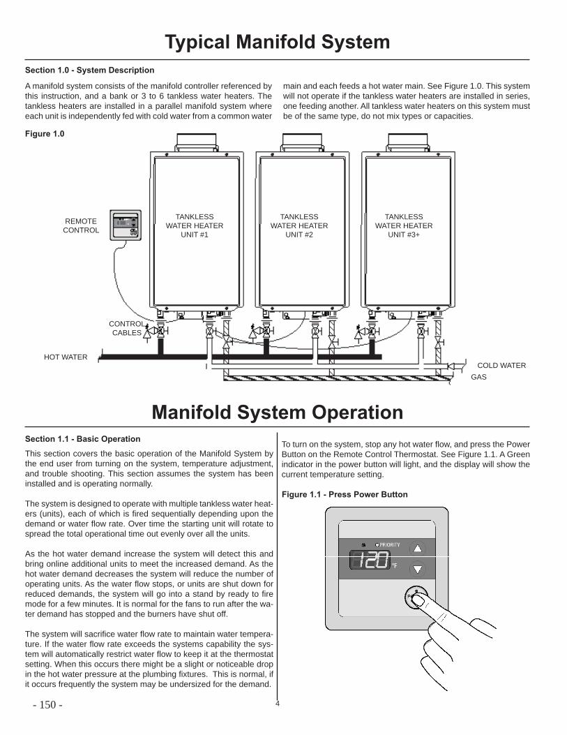
4
Typical Manifold System
A manifold system consists of the manifold controller referenced by this instruction, and a bank or 3 to 6 tankless water heaters. The tankless heaters are installed in a parallel manifold system where each unit is independently fed with cold water from a common water
main and each feeds a hot water main. See Figure 1.0. This system will not operate if the tankless water heaters are installed in series, one feeding another. All tankless water heaters on this system must be of the same type, do not mix types or capacities.
Section 1.1 - Basic Operation
This section covers the basic operation of the Manifold System by the end user from turning on the system, temperature adjustment, and trouble shooting. This section assumes the system has been installed and is operating normally.
The system is designed to operate with multiple tankless water heat-ers (units), each of which is fi red sequentially depending upon the demand or water fl ow rate. Over time the starting unit will rotate to spread the total operational time out evenly over all the units.
As the hot water demand increase the system will detect this and bring online additional units to meet the increased demand. As the hot water demand decreases the system will reduce the number of operating units. As the water fl ow stops, or units are shut down for reduced demands, the system will go into a stand by ready to fi re mode for a few minutes. It is normal for the fans to run after the wa-ter demand has stopped and the burners have shut off.
The system will sacrifi ce water fl ow rate to maintain water tempera-ture. If the water fl ow rate exceeds the systems capability the sys-tem will automatically restrict water fl ow to keep it at the thermostat setting. When this occurs there might be a slight or noticeable drop in the hot water pressure at the plumbing fi xtures. This is normal, if it occurs frequently the system may be undersized for the demand.
Section 1.0 - System Description
Figure 1.0
HOT WATERCOLD WATER
GAS
CONTROL CABLES
REMOTE CONTROL
TANKLESS WATER HEATER
UNIT #1
TANKLESS WATER HEATER
UNIT #2
TANKLESS WATER HEATER
UNIT #3+
Manifold System OperationTo turn on the system, stop any hot water fl ow, and press the Power Button on the Remote Control Thermostat. See Figure 1.1. A Green indicator in the power button will light, and the display will show the current temperature setting.
Figure 1.1 - Press Power Button
- 150 -
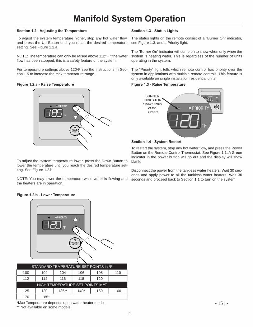
5
Section 1.2 - Adjusting the Temperature
To adjust the system temperature higher, stop any hot water fl ow, and press the Up Button until you reach the desired temperature setting. See Figure 1.2.a.
NOTE: The temperature can only be raised above 112ºF if the water fl ow has been stopped, this is a safety feature of the system.
For temperature settings above 120ºF see the instructions in Sec-tion 1.5 to increase the max temperature range.
Manifold System Operation
To adjust the system temperature lower, press the Down Button to lower the temperature until you reach the desired temperature set-ting. See Figure 1.2.b.
NOTE: You may lower the temperature while water is fl owing and the heaters are in operation.
Figure 1.2.a - Raise Temperature
Figure 1.2.b - Lower Temperature
Section 1.3 - Status Lights
The status lights on the remote consist of a “Burner On” indicator, see Figure 1.3, and a Priority light.
The “Burner On” indicator will come on to show when only when the system is heating water. This is regardless of the number of units operating in the system.
The “Priority” light tells which remote control has priority over the system in applications with multiple remote controls. This feature is only available on single installation residential units.Figure 1.3 - Raise Temperature
BURNERINDICATORShow Status
of the Burners
Section 1.4 - System RestartTo restart the system, stop any hot water fl ow, and press the Power Button on the Remote Control Thermostat. See Figure 1.1. A Green indicator in the power button will go out and the display will show blank.
Disconnect the power from the tankless water heaters. Wait 30 sec-onds and apply power to all the tankless water heaters. Wait 30 seconds and proceed back to Section 1.1 to turn on the system.
STANDARD TEMPERATURE SET POINTS in ºF100 102 104 106 108 110112 114 116 118 120
HIGH TEMPERATURE SET POINTS in ºF125 130 135** 140* 150 160170 185*
*Max Temperature depends upon water heater model. ** Not available on some models.
- 151 -
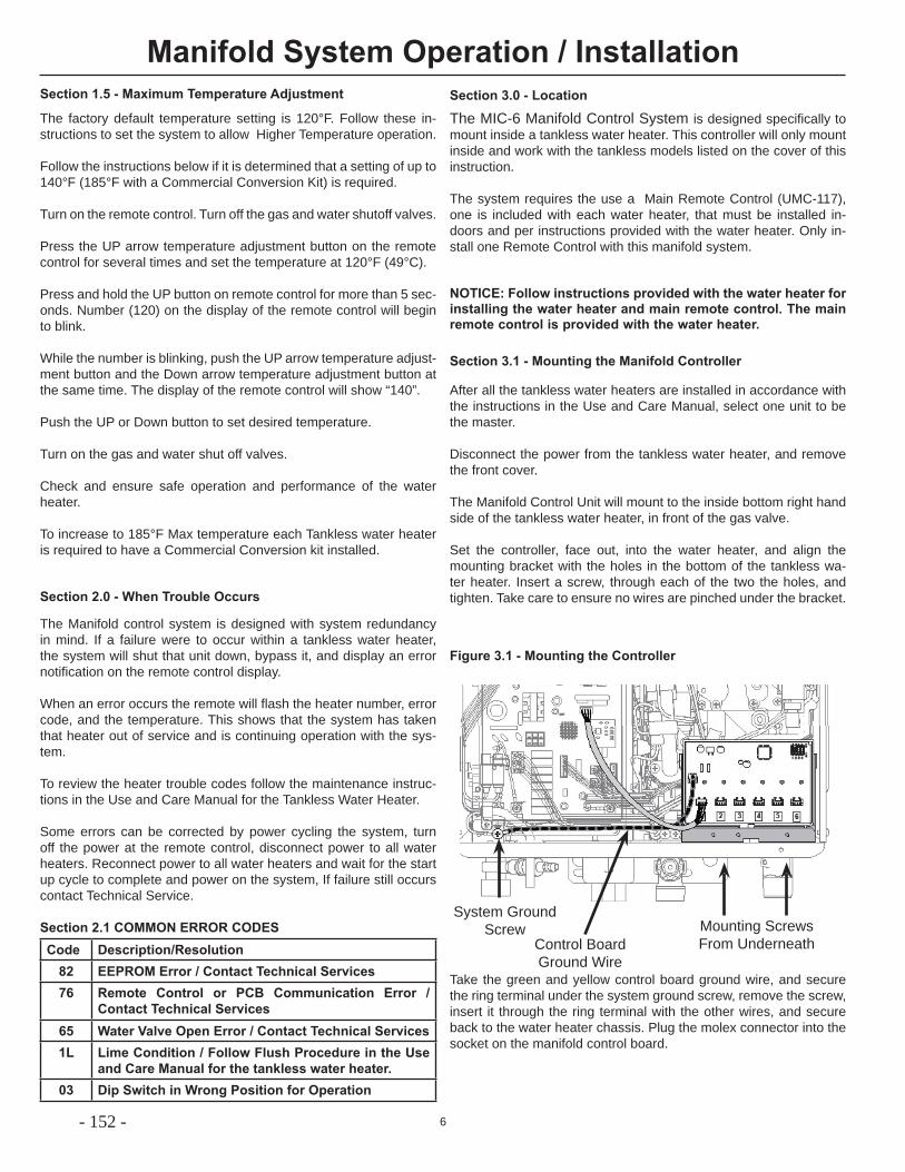
6
The Manifold control system is designed with system redundancy in mind. If a failure were to occur within a tankless water heater, the system will shut that unit down, bypass it, and display an error notifi cation on the remote control display.
When an error occurs the remote will fl ash the heater number, error code, and the temperature. This shows that the system has taken that heater out of service and is continuing operation with the sys-tem.
To review the heater trouble codes follow the maintenance instruc-tions in the Use and Care Manual for the Tankless Water Heater.
Some errors can be corrected by power cycling the system, turn off the power at the remote control, disconnect power to all water heaters. Reconnect power to all water heaters and wait for the start up cycle to complete and power on the system, If failure still occurs contact Technical Service.
Section 2.1 COMMON ERROR CODESCode Description/Resolution
82 EEPROM Error / Contact Technical Services76 Remote Control or PCB Communication Error /
Contact Technical Services65 Water Valve Open Error / Contact Technical Services1L Lime Condition / Follow Flush Procedure in the Use
and Care Manual for the tankless water heater.03 Dip Switch in Wrong Position for Operation
Manifold System Operation / Installation
Section 2.0 - When Trouble Occurs
NOTICE: Follow instructions provided with the water heater for installing the water heater and main remote control. The main remote control is provided with the water heater.
Section 3.0 - Location
The MIC-6 Manifold Control System is designed specifi cally to mount inside a tankless water heater. This controller will only mount inside and work with the tankless models listed on the cover of this instruction.
The system requires the use a Main Remote Control (UMC-117), one is included with each water heater, that must be installed in-doors and per instructions provided with the water heater. Only in-stall one Remote Control with this manifold system.
Section 3.1 - Mounting the Manifold Controller
After all the tankless water heaters are installed in accordance with the instructions in the Use and Care Manual, select one unit to be the master.
Disconnect the power from the tankless water heater, and remove the front cover.
The Manifold Control Unit will mount to the inside bottom right hand side of the tankless water heater, in front of the gas valve.
Set the controller, face out, into the water heater, and align the mounting bracket with the holes in the bottom of the tankless wa-ter heater. Insert a screw, through each of the two the holes, and tighten. Take care to ensure no wires are pinched under the bracket.
Figure 3.1 - Mounting the Controller
Control BoardGround Wire
System GroundScrew Mounting Screws
From Underneath
Take the green and yellow control board ground wire, and secure the ring terminal under the system ground screw, remove the screw, insert it through the ring terminal with the other wires, and secure back to the water heater chassis. Plug the molex connector into the socket on the manifold control board.
The factory default temperature setting is 120°F. Follow these in-structions to set the system to allow Higher Temperature operation.
Follow the instructions below if it is determined that a setting of up to 140°F (185°F with a Commercial Conversion Kit) is required.
Turn on the remote control. Turn off the gas and water shutoff valves.
Press the UP arrow temperature adjustment button on the remote control for several times and set the temperature at 120°F (49°C).
Press and hold the UP button on remote control for more than 5 sec-onds. Number (120) on the display of the remote control will begin to blink.
While the number is blinking, push the UP arrow temperature adjust-ment button and the Down arrow temperature adjustment button at the same time. The display of the remote control will show “140”.
Push the UP or Down button to set desired temperature.
Turn on the gas and water shut off valves.
Check and ensure safe operation and performance of the water heater.
To increase to 185°F Max temperature each Tankless water heater is required to have a Commercial Conversion kit installed.
Section 1.5 - Maximum Temperature Adjustment
- 152 -
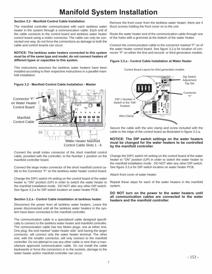
7
Section 3.2 - Manifold Control Cable InstallationThe manifold controller communicated with each tankless water heater in the system through a communication cable. Each end of the cable connects to the control board and tankless water heater control board using a molex connector. The cable can only be con-nected one way, do not force the connections as damage to both the cable and control boards can occur.
NOTICE: The tankless water heaters connected to this system must be of the same type and model, do not connect heaters of different types or capacities to this system.
This instructions assumes the tankless water heaters have been installed according to their respective instructions in a parallel mani-fold installation.
Section 3.2.a - Control Cable Installation at tankless heater.
Remove the front cover from the tankless water heater; there are 4 (four) screws holding the front cover on to the unit.
Route the water heater end of the communication cable through one of the holes with a grommet at the bottom of the water heater.
Connect the communication cable to the connector marked “F” on of the water heater control board. See fi gure 3.2.a for location of con-nector “F” on either the fi rst and second or third generation models.
Manifold System Installation
ManifoldControl Cable
Water Heater Manifold Control Cable Slots 1 - 6
Connector “F”on Water Heater
Control Board
Figure 3.2 - Manifold Control Cable Installation - Master
Connect the small molex connector of the short manifold control cable, provided with the controller, to the Number 1 position on the manifold controller board.
Connect the large molex connector of the short manifold control ca-ble to the Connector “F” on the tankless water heater control board.
Change the DIP1 switch #4 setting on the control board of the water heater to “ON” position (UP) in order to switch the water heater to the manifold installation mode. DO NOT alter any other DIP switch. See fi gure 3.2.a for DIP switch location on water heater PCB.
Disconnect the power from all tankless water heaters. Leave the power disconnected until all the tankless water heaters in the sys-tem have been connected to the manifold controller.
The communication cable is a specialized cable designed specifi -cally to connect to the tankless water heater and manifold controller. The communication cable has two Molex plugs, one at either end. One plug, the end marked “water heater side” and having the larger connector, will connect only the water heater terminal. The other end, with the smaller connector, will only connect to the manifold controller. Do not attempt to use any other cable or wire than a man-ufacture approved communication cable. Do not install the cable backwards or force the connectors in to the sockets, damage to the water heater and/or manifold controller can occur.
Secure the cable with the wire clamp and screw included with the cable to the edge of the control board as illustrated in fi gure 3.2.a.
NOTICE: The DIP switch settings on the water heaters must be changed for the water heaters to be controlled by the manifold controller.
Change the DIP1 switch #4 setting on the control board of the water heater to “ON” position (UP) in order to switch the water heater to the manifold installation mode. DO NOT alter any other DIP switch. See fi gure 3.2.a for DIP switch location on water heater PCB.
Attach front cover of water heater.
Repeat these steps for each of the water heaters in the manifold system.
DO NOT turn on the power to the water heaters until all communication cables are connected to the water heaters and the manifold controller.
Figure 3.2.a - Control Cable Installation at Water Heater
Control Board Layout for third generation models
DIP 1 Number 4 Switch in the “ON”
Position
Dip SwitchAdjustment
Top Set
Connector“F”
Wire Clamp
- 153 -
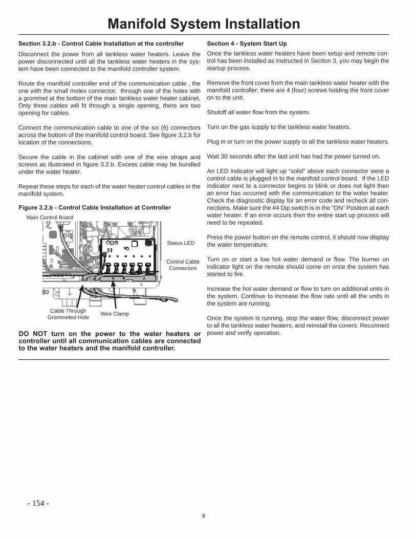
8
Manifold System Installation
Disconnect the power from all tankless water heaters. Leave the power disconnected until all the tankless water heaters in the sys-tem have been connected to the manifold controller system.
Route the manifold controller end of the communication cable , the one with the small molex connector, through one of the holes with a grommet at the bottom of the main tankless water heater cabinet. Only three cables will fi t through a single opening, there are two opening for cables.
Connect the communication cable to one of the six (6) connectors across the bottom of the manifold control board. See fi gure 3.2.b for location of the connections.
Secure the cable in the cabinet with one of the wire straps and screws as illustrated in fi gure 3.2.b. Excess cable may be bundled under the water heater.
Repeat these steps for each of the water heater control cables in the manifold system.
Section 3.2.b - Control Cable Installation at the controller
Figure 3.2.b - Control Cable Installation at Controller
Control CableConnectors
DO NOT turn on the power to the water heaters or controller until all communication cables are connected to the water heaters and the manifold controller.
Wire ClampCable ThroughGrommeted Hole
Main Control Board
Section 4 - System Start UpOnce the tankless water heaters have been setup and remote con-trol has been installed as instructed in Section 3, you may begin the startup process.
Remove the front cover from the main tankless water heater with the manifold controller; there are 4 (four) screws holding the front cover on to the unit.
Shutoff all water fl ow from the system.
Turn on the gas supply to the tankless water heaters.
Plug in or turn on the power supply to all the tankless water heaters.
Wait 30 seconds after the last unit has had the power turned on.
An LED indicator will light up “solid” above each connector were a control cable is plugged in to the manifold control board. If the LED indicator next to a connector begins to blink or does not light then an error has occurred with the communication to the water heater. Check the diagnostic display for an error code and recheck all con-nections. Make sure the #4 Dip switch is in the “ON” Position at each water heater. If an error occurs then the entire start up process will need to be repeated.
Press the power button on the remote control, it should now display the water temperature.
Turn on or start a low hot water demand or fl ow. The burner on indicator light on the remote should come on once the system has started to fi re.
Increase the hot water demand or fl ow to turn on additional units in the system. Continue to increase the fl ow rate until all the units in the system are running.
Once the system is running, stop the water fl ow, disconnect power to all the tankless water heaters, and reinstall the covers. Reconnect power and verify operation.
Status LED
- 154 -
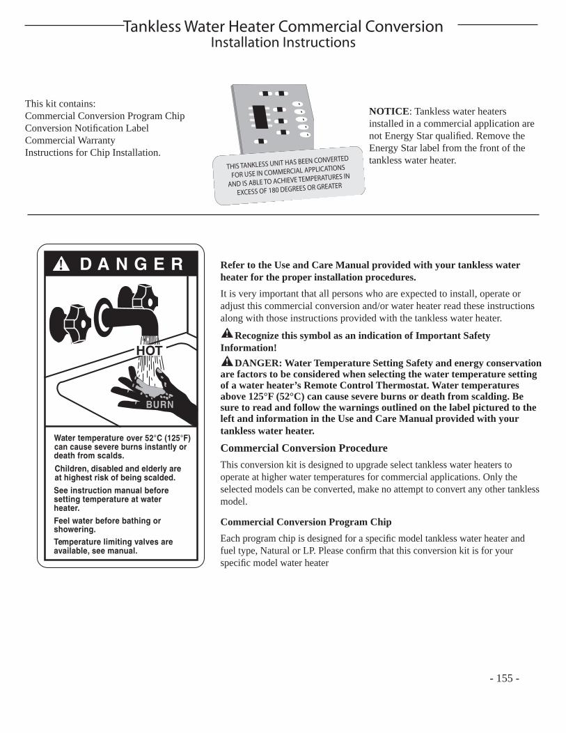
Tankless Water Heater Commercial ConversionInstallation Instructions
Refer to the Use and Care Manual provided with your tankless water heater for the proper installation procedures. It is very important that all persons who are expected to install, operate or adjust this commercial conversion and/or water heater read these instructions along with those instructions provided with the tankless water heater.! Recognize this symbol as an indication of Important Safety
Information!! DANGER: Water Temperature Setting Safety and energy conservation
are factors to be considered when selecting the water temperature setting of a water heater’s Remote Control Thermostat. Water temperatures above 125°F (52°C) can cause severe burns or death from scalding. Be sure to read and follow the warnings outlined on the label pictured to the left and information in the Use and Care Manual provided with your tankless water heater.
Commercial Conversion Procedure This conversion kit is designed to upgrade select tankless water heaters to operate at higher water temperatures for commercial applications. Only the selected models can be converted, make no attempt to convert any other tankless model.
Commercial Conversion Program ChipEach program chip is designed for a specifi c model tankless water heater and fuel type, Natural or LP. Please confi rm that this conversion kit is for your specifi c model water heater
D A N G E R!
HOT
Water temperature
death from scalds.
Children, disabled and elderly areat highest risk of being scalded.
See instruction manual beforesetting temperature at waterheater.Feel water before bathing orshowering.Temperature limiting valves areavailable, see manual.
BURN
over 52°C (125°F)can cause severe burns instantly or
- 155 -
This kit contains: Commercial Conversion Program ChipConversion Notifi cation LabelCommercial WarrantyInstructions for Chip Installation.
NOTICE: Tankless water heaters installed in a commercial application are not Energy Star qualifi ed. Remove the Energy Star label from the front of the tankless water heater.
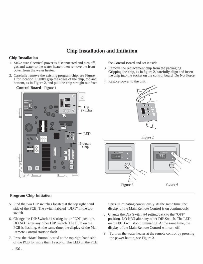
Chip Installation and InitiationChip Installation 1. Make sure electrical power is disconnected and turn off
gas and water to the water heater, then remove the front cover from the water heater.
2. Carefully remove the existing program chip, see Figure 1 for location. Lightly grip the edges of the chip, top and bottom, as in Figure 2, and pull the chip straight out from
the Control Board and set it aside.3. Remove the replacement chip from the packaging.
Gripping the chip, as in fi gure 2, carefully align and insert the chip into the socket on the control board. Do Not Force
4. Restore power to the unit.
ON
1 2 3 4
ON
OFF
ON
1 2 3 4
ON
OFF
1 2 3 4
1 2 3 4
DIP
2D
IP1
MIN MAX ADJ
LED
Control Board - Figure 1
Dip Switches
Program Chip
LED
Program Chip Initiation
Figure 2
°F
PRIORITY
POWERON/OFF
°F
PRIORITY
POWERON/OFF
Figure 4Figure 3
5. Find the two DIP switches located at the top right hand side of the PCB. The switch labeled “DIP1” in the top switch.
6. Change the DIP Switch #4 setting to the “ON” position. DO NOT alter any other DIP Switch. The LED on the PCB is fl ashing. At the same time, the display of the Main Remote Control starts to fl ash.
7. Press the “Max” button located at the top right hand side of the PCB for more than 1 second. The LED on the PCB
starts illuminating continuously. At the same time, the display of the Main Remote Control is on continuously.
8. Change the DIP Switch #4 setting back to the “OFF” position. DO NOT alter any other DIP Switch. The LED on the PCB will stop illuminating. At the same time, the display of the Main Remote Control will turn off.
9. Turn on the water heater at the remote control by pressing the power button, see Figure 3.
- 156 -
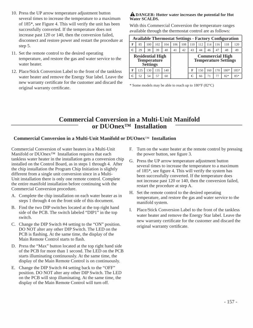
10. Press the UP arrow temperature adjustment button several times to increase the temperature to a maximum of 185*, see Figure 4. This will verify the unit has been successfully converted. If the temperature does not increase past 120 or 140, then the conversion failed, disconnect and restore power and restart the procedure at step 5.
11. Set the remote control to the desired operating temperature, and restore the gas and water service to the water heater.
12. Place/Stick Conversion Label to the front of the tankless water heater and remove the Energy Star label. Leave the new warranty certifi cate for the customer and discard the original warranty certifi cate.
Available Thermostat Settings - Factory Confi gurationF 85 100 102 104 106 108 110 112 114 116 118 120
C 29 38 39 40 41 42 43 44 46 47 48 49
Residential High Temperature
Settings
Commercial High Temperature Settings
F 125 130 135 140 F 150 160 170 180* 185*
C 52 54 57 60 C 66 71 77 82* 85*
With this Commercial Conversion the temperature ranges available through the thermostat control are as follows:
* Some models may be able to reach up to 180°F (82°C)
! DANGER: Hotter water increases the potential for Hot Water SCALDS.
Commercial Conversion in a Multi-Unit Manifold or DUOnex™ Installation
Commercial Conversion of water heaters in a Multi-Unit Manifold or DUOnex™ Installation requires that each tankless water heater in the installation gets a conversion chip installed on the Control Board, as in steps 1 through 4. After the chip installation the Program Chip Initiation is slightly different from a single unit conversion since in a Multi-Unit installation there is only one remote control. Complete the entire manifold installation before continuing with the Commercial Conversion procedure.A. Complete the chip installation on each water heater as in
steps 1 through 4 on the front side of this document.B. Find the two DIP switches located at the top right hand
side of the PCB. The switch labeled “DIP1” in the top switch.
C. Change the DIP Switch #4 setting to the “ON” position. DO NOT alter any other DIP Switch. The LED on the PCB is fl ashing. At the same time, the display of the Main Remote Control starts to fl ash.
D. Press the “Max” button located at the top right hand side of the PCB for more than 1 second. The LED on the PCB starts illuminating continuously. At the same time, the display of the Main Remote Control is on continuously.
E. Change the DIP Switch #4 setting back to the “OFF” position. DO NOT alter any other DIP Switch. The LED on the PCB will stop illuminating. At the same time, the display of the Main Remote Control will turn off.
F. Turn on the water heater at the remote control by pressing the power button, see fi gure 3.
G. Press the UP arrow temperature adjustment button several times to increase the temperature to a maximum of 185*, see fi gure 4. This will verify the system has been successfully converted. If the temperature does not increase past 120 or 140, then the conversion failed, restart the procedure at step A.
H. Set the remote control to the desired operating temperature, and restore the gas and water service to the manifold system.
I. Place/Stick Conversion Label to the front of the tankless water heater and remove the Energy Star label. Leave the new warranty certifi cate for the customer and discard the original warranty certifi cate.
Commercial Conversion in a Multi-Unit Manifold or DUOnex™ Installation
- 157 -
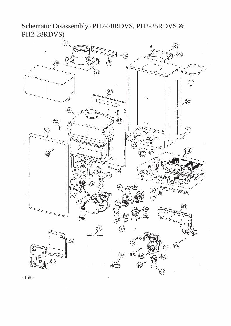
- 158 -
Schematic Disassembly (PH2-20RDVS, PH2-25RDVS &PH2-28RDVS)
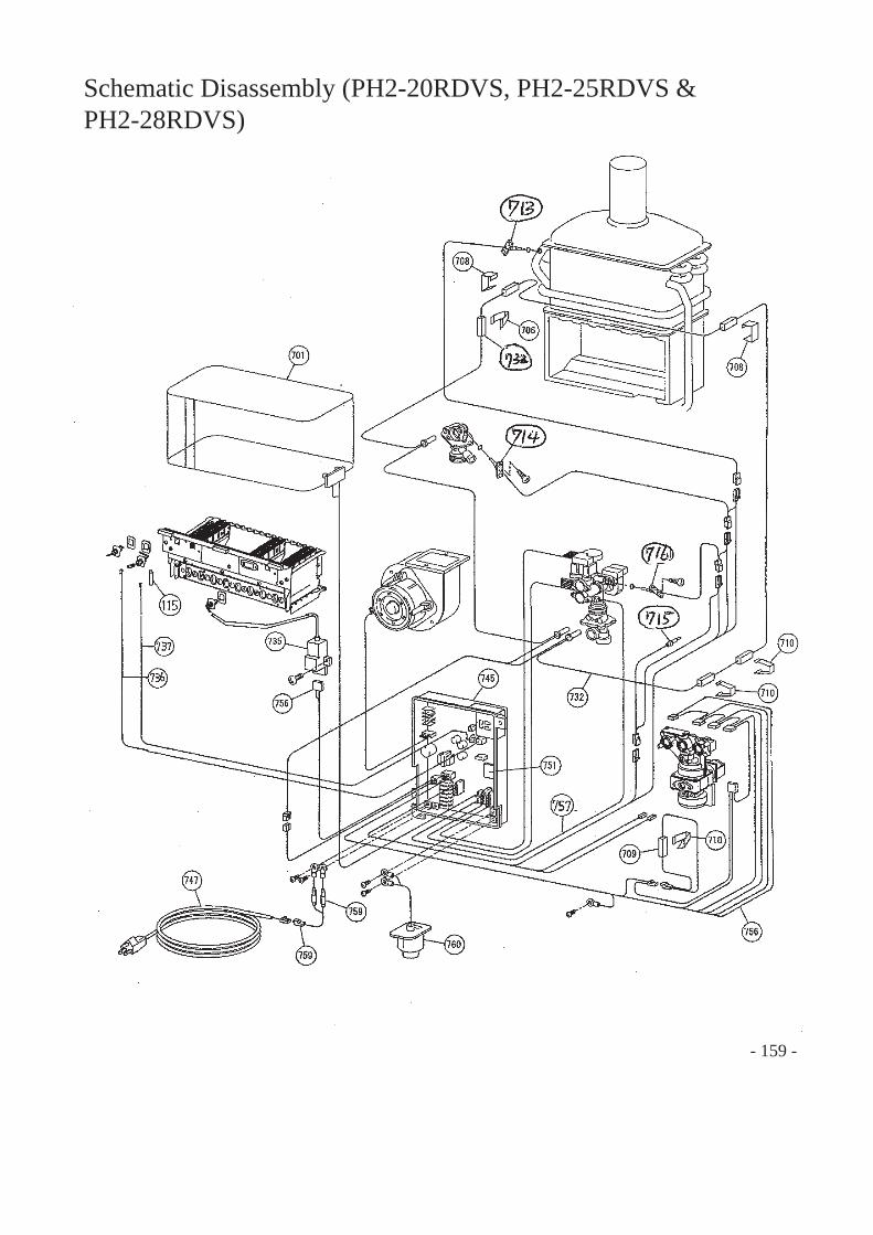
- 159 -
Schematic Disassembly (PH2-20RDVS, PH2-25RDVS &PH2-28RDVS)
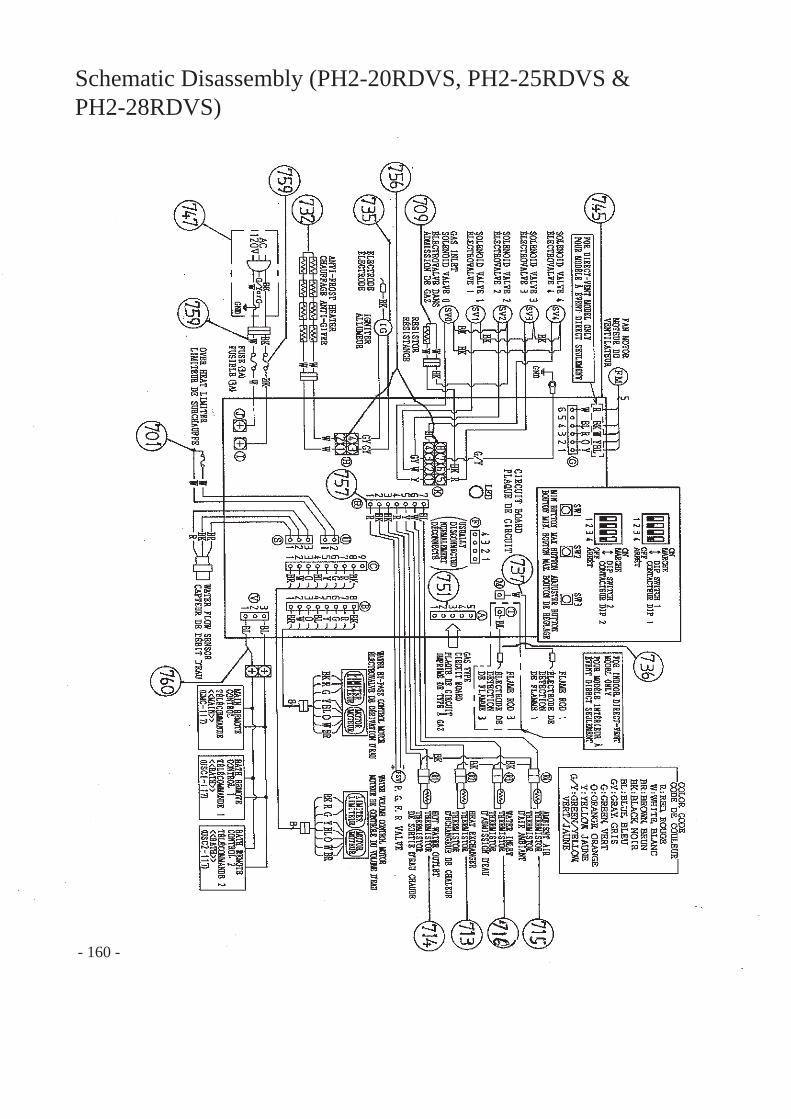
- 160 -
Schematic Disassembly (PH2-20RDVS, PH2-25RDVS &PH2-28RDVS)
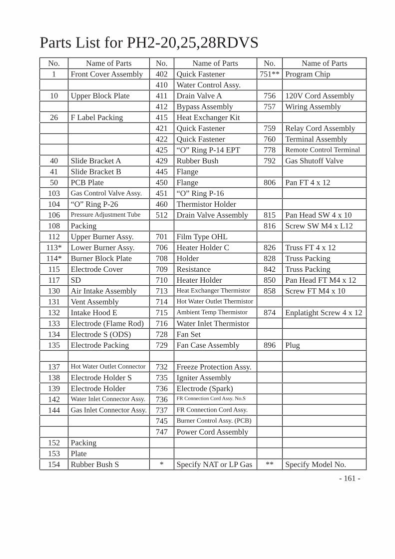
- 161 -
Parts List for PH2-20,25,28RDVSNo. Name of Parts No. Name of Parts No. Name of Parts1 Front Cover Assembly 402 Quick Fastener 751** Program Chip
410 Water Control Assy.10 Upper Block Plate 411 Drain Valve A 756 120V Cord Assembly
412 Bypass Assembly 757 Wiring Assembly26 F Label Packing 415 Heat Exchanger Kit
421 Quick Fastener 759 Relay Cord Assembly422 Quick Fastener 760 Terminal Assembly425 “O” Ring P-14 EPT 778 Remote Control Terminal
40 Slide Bracket A 429 Rubber Bush 792 Gas Shutoff Valve41 Slide Bracket B 445 Flange50 PCB Plate 450 Flange 806 Pan FT 4 x 12103 Gas Control Valve Assy. 451 “O” Ring P-16104 “O” Ring P-26 460 Thermistor Holder106 Pressure Adjustment Tube 512 Drain Valve Assembly 815 Pan Head SW 4 x 10108 Packing 816 Screw SW M4 x L12112 Upper Burner Assy. 701 Film Type OHL113* Lower Burner Assy. 706 Heater Holder C 826 Truss FT 4 x 12114* Burner Block Plate 708 Holder 828 Truss Packing 115 Electrode Cover 709 Resistance 842 Truss Packing117 SD 710 Heater Holder 850 Pan Head FT M4 x 12130 Air Intake Assembly 713 Heat Exchanger Thermistor 858 Screw FT M4 x 10131 Vent Assembly 714 Hot Water Outlet Thermistor
132 Intake Hood E 715 Ambient Temp Thermistor 874 Enplatight Screw 4 x 12133 Electrode (Flame Rod) 716 Water Inlet Thermistor134 Electrode S (ODS) 728 Fan Set135 Electrode Packing 729 Fan Case Assembly 896 Plug
137 Hot Water Outlet Connector 732 Freeze Protection Assy.138 Electrode Holder S 735 Igniter Assembly139 Electrode Holder 736 Electrode (Spark)142 Water Inlet Connector Assy. 736 FR Connection Cord Assy. No.S
144 Gas Inlet Connector Assy. 737 FR Connection Cord Assy.
745 Burner Control Assy. (PCB)
747 Power Cord Assembly152 Packing153 Plate154 Rubber Bush S * Specify NAT or LP Gas ** Specify Model No.
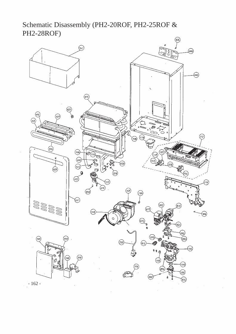
- 162 -
Schematic Disassembly (PH2-20ROF, PH2-25ROF &PH2-28ROF)
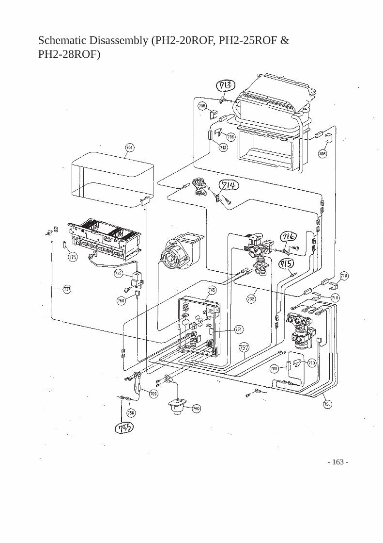
- 163 -
Schematic Disassembly (PH2-20ROF, PH2-25ROF &PH2-28ROF)
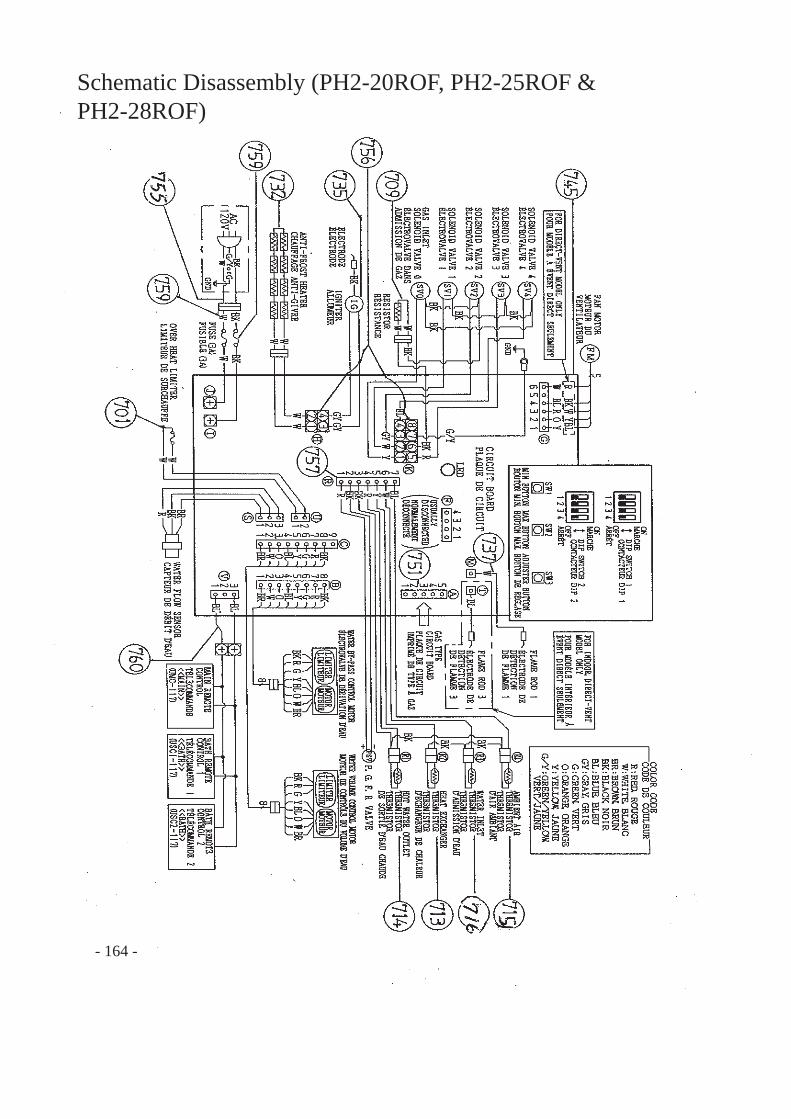
- 164 -
Schematic Disassembly (PH2-20ROF, PH2-25ROF &PH2-28ROF)
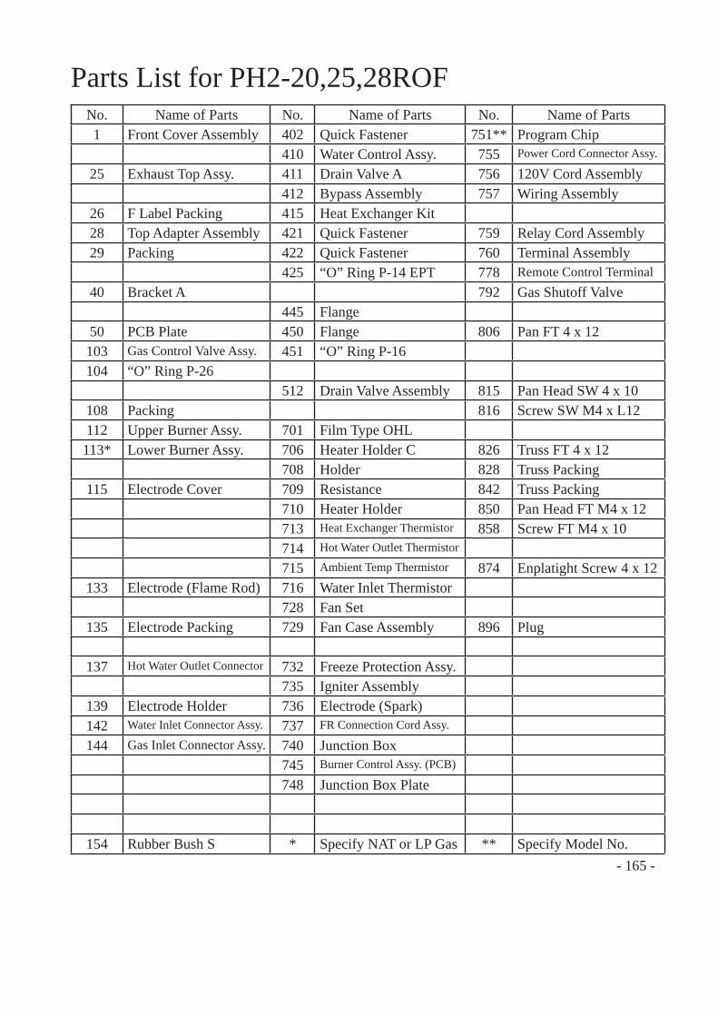
- 165 -
Parts List for PH2-20,25,28ROFNo. Name of Parts No. Name of Parts No. Name of Parts1 Front Cover Assembly 402 Quick Fastener 751** Program Chip
410 Water Control Assy. 755 Power Cord Connector Assy.
25 Exhaust Top Assy. 411 Drain Valve A 756 120V Cord Assembly412 Bypass Assembly 757 Wiring Assembly
26 F Label Packing 415 Heat Exchanger Kit28 Top Adapter Assembly 421 Quick Fastener 759 Relay Cord Assembly29 Packing 422 Quick Fastener 760 Terminal Assembly
425 “O” Ring P-14 EPT 778 Remote Control Terminal40 Bracket A 792 Gas Shutoff Valve
445 Flange50 PCB Plate 450 Flange 806 Pan FT 4 x 12103 Gas Control Valve Assy. 451 “O” Ring P-16104 “O” Ring P-26
512 Drain Valve Assembly 815 Pan Head SW 4 x 10108 Packing 816 Screw SW M4 x L12112 Upper Burner Assy. 701 Film Type OHL113* Lower Burner Assy. 706 Heater Holder C 826 Truss FT 4 x 12
708 Holder 828 Truss Packing 115 Electrode Cover 709 Resistance 842 Truss Packing
710 Heater Holder 850 Pan Head FT M4 x 12713 Heat Exchanger Thermistor 858 Screw FT M4 x 10714 Hot Water Outlet Thermistor
715 Ambient Temp Thermistor 874 Enplatight Screw 4 x 12133 Electrode (Flame Rod) 716 Water Inlet Thermistor
728 Fan Set135 Electrode Packing 729 Fan Case Assembly 896 Plug
137 Hot Water Outlet Connector 732 Freeze Protection Assy.735 Igniter Assembly
139 Electrode Holder 736 Electrode (Spark)142 Water Inlet Connector Assy. 737 FR Connection Cord Assy.
144 Gas Inlet Connector Assy. 740 Junction Box745 Burner Control Assy. (PCB)
748 Junction Box Plate
154 Rubber Bush S * Specify NAT or LP Gas ** Specify Model No.
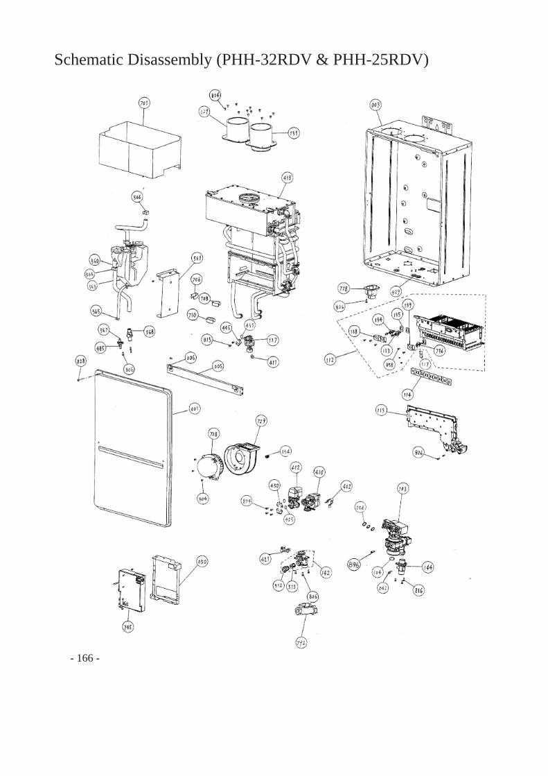
Schematic Disassembly (PHH-32RDV & PHH-25RDV)
- 166 -
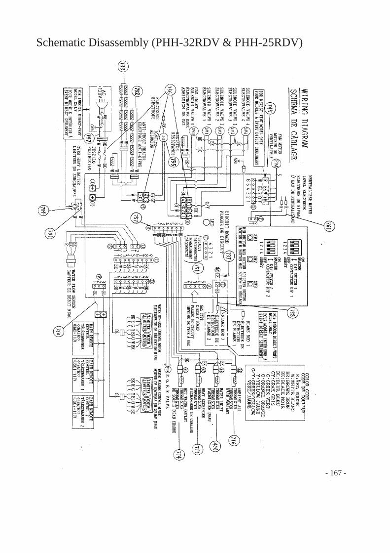
Schematic Disassembly (PHH-32RDV & PHH-25RDV)
- 167 -
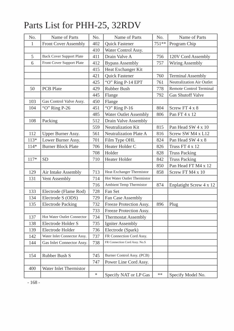
Parts List for PHH-25, 32RDVNo. Name of Parts No. Name of Parts No. Name of Parts1 Front Cover Assembly 402 Quick Fastener 751** Program Chip
410 Water Control Assy.5 Back Cover Support Plate 411 Drain Valve A 756 120V Cord Assembly6 Front Cover Support Plate 412 Bypass Assembly 757 Wiring Assembly
415 Heat Exchanger Kit421 Quick Fastener 760 Terminal Assembly425 “O” Ring P-14 EPT 761 Neutralization Air Outlet
50 PCB Plate 429 Rubber Bush 778 Remote Control Terminal445 Flange 792 Gas Shutoff Valve
103 Gas Control Valve Assy. 450 Flange104 “O” Ring P-26 451 “O” Ring P-16 804 Screw FT 4 x 8
485 Water Outlet Assembly 806 Pan FT 4 x 12108 Packing 512 Drain Valve Assembly
559 Neutralization Kit 815 Pan Head SW 4 x 10112 Upper Burner Assy. 561 Neutralization Plate A 816 Screw SW M4 x L12113* Lower Burner Assy. 701 Film Type OHL 824 Pan Head SW 4 x 8114* Burner Block Plate 706 Heater Holder C 826 Truss FT 4 x 12
708 Holder 828 Truss Packing 117* SD 710 Heater Holder 842 Truss Packing
850 Pan Head FT M4 x 12129 Air Intake Assembly 713 Heat Exchanger Thermistor 858 Screw FT M4 x 10131 Vent Assembly 714 Hot Water Outlet Thermistor
716 Ambient Temp Thermistor 874 Enplatight Screw 4 x 12133 Electrode (Flame Rod) 728 Fan Set134 Electrode S (ODS) 729 Fan Case Assembly135 Electrode Packing 732 Freeze Protection Assy. 896 Plug
733 Freeze Protection Assy.137 Hot Water Outlet Connector 734 Thermostat Assembly138 Electrode Holder S 735 Igniter Assembly139 Electrode Holder 736 Electrode (Spark)142 Water Inlet Connector Assy. 737 FR Connection Cord Assy.
144 Gas Inlet Connector Assy. 738 FR Connection Cord Assy. No.S
154 Rubber Bush S 745 Burner Control Assy. (PCB)
747 Power Line Cord Assy.400 Water Inlet Thermistor
* Specify NAT or LP Gas ** Specify Model No.- 168 -
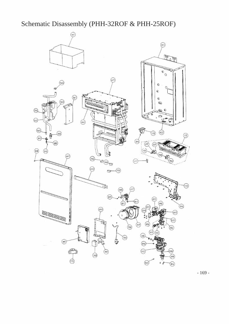
- 169 -
Schematic Disassembly (PHH-32ROF & PHH-25ROF)
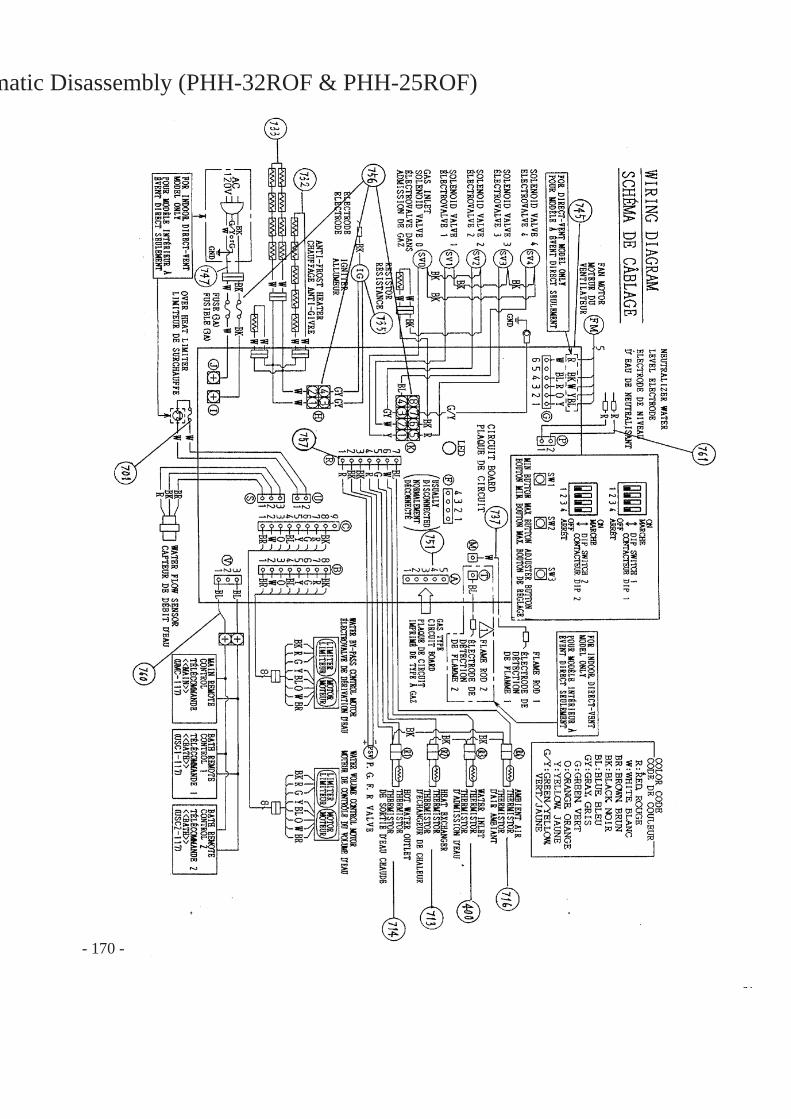
- 170 -
matic Disassembly (PHH-32ROF & PHH-25ROF)
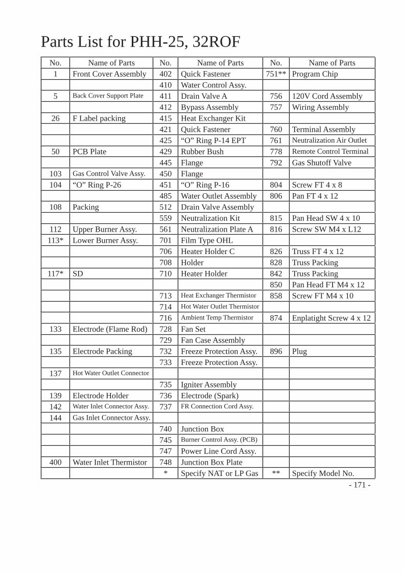
- 171 -
Parts List for PHH-25, 32ROFNo. Name of Parts No. Name of Parts No. Name of Parts1 Front Cover Assembly 402 Quick Fastener 751** Program Chip
410 Water Control Assy.5 Back Cover Support Plate 411 Drain Valve A 756 120V Cord Assembly
412 Bypass Assembly 757 Wiring Assembly26 F Label packing 415 Heat Exchanger Kit
421 Quick Fastener 760 Terminal Assembly425 “O” Ring P-14 EPT 761 Neutralization Air Outlet
50 PCB Plate 429 Rubber Bush 778 Remote Control Terminal445 Flange 792 Gas Shutoff Valve
103 Gas Control Valve Assy. 450 Flange104 “O” Ring P-26 451 “O” Ring P-16 804 Screw FT 4 x 8
485 Water Outlet Assembly 806 Pan FT 4 x 12108 Packing 512 Drain Valve Assembly
559 Neutralization Kit 815 Pan Head SW 4 x 10112 Upper Burner Assy. 561 Neutralization Plate A 816 Screw SW M4 x L12113* Lower Burner Assy. 701 Film Type OHL
706 Heater Holder C 826 Truss FT 4 x 12708 Holder 828 Truss Packing
117* SD 710 Heater Holder 842 Truss Packing850 Pan Head FT M4 x 12
713 Heat Exchanger Thermistor 858 Screw FT M4 x 10714 Hot Water Outlet Thermistor
716 Ambient Temp Thermistor 874 Enplatight Screw 4 x 12133 Electrode (Flame Rod) 728 Fan Set
729 Fan Case Assembly135 Electrode Packing 732 Freeze Protection Assy. 896 Plug
733 Freeze Protection Assy.137 Hot Water Outlet Connector
735 Igniter Assembly139 Electrode Holder 736 Electrode (Spark)142 Water Inlet Connector Assy. 737 FR Connection Cord Assy.
144 Gas Inlet Connector Assy.740 Junction Box745 Burner Control Assy. (PCB)
747 Power Line Cord Assy.400 Water Inlet Thermistor 748 Junction Box Plate
* Specify NAT or LP Gas ** Specify Model No.

Paloma Industries, Inc.2151 Eastman AvenueOxnard, CA 93030Phone: (805) 278-5499Fax: (805) 278-5468
Tech Support Center: (800) 432-8373
Printed in USA
2011-08