tank blanketing regulators - teknopoli · 2018-11-07 · technical data tank blanketing regulators...
TRANSCRIPT
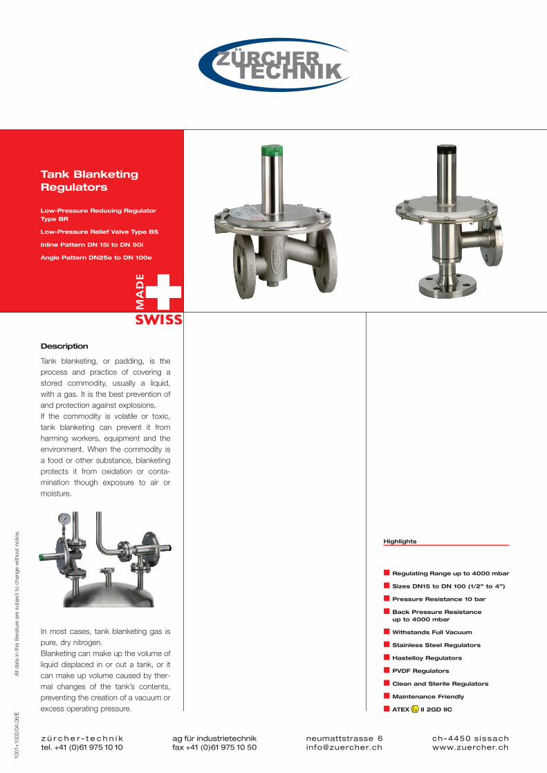
Tank Blanketing Regulators
Low-Pressure Reducing Regulator
Type BR
Low-Pressure Relief Valve Type BS
Inline Pattern DN 15i to DN 50i
Angle Pattern DN25e to DN 100e
Description
Tank blanketing, or padding, is the process and practice of covering astored commodity, usually a liquid,with a gas. It is the best prevention ofand protection against explosions.If the commodity is volatile or toxic,tank blanketing can prevent it fromharming workers, equipment and theenvironment. When the commodity is a food or other substance, blanketingprotects it from oxidation or conta-mination though exposure to air ormoisture.
In most cases, tank blanketing gas ispure, dry nitrogen.Blanketing can make up the volume ofliquid displaced in or out a tank, or itcan make up volume caused by ther-mal changes of the tank’s contents,preventing the creation of a vacuum orexcess operating pressure.
Highlights
� Regulating Range up to 4000 mbar
� Sizes DN15 to DN 100 (1/2” to 4”)
� Pressure Resistance 10 bar
� Back Pressure Resistance up to 4000 mbar
� Withstands Full Vacuum
� Stainless Steel Regulators
� Hastelloy Regulators
� PVDF Regulators
� Clean and Sterile Regulators
� Maintenance Friendly
� ATEX II 2GD IIC
z ü r c h e r - t e c h n i ktel. +41 (0)61 975 10 10
ag für industrietechnikfax +41 (0)61 975 10 50
ch-4450 sissachwww.zuercher.ch
neumattstrasse [email protected]
1001
+100
2/04
.06/
EA
ll da
ta in
thi
s lit
erat
ure
are
subj
ect
to c
hang
e w
ithou
t no
tice.
1001+1002/04.06/E_BR+BS_ROT 19.04.2006 14:15 Uhr Seite 1

Technical Data Tank Blanketing Regulators
z ü r c h e r - t e c h n i ktel. +41 (0)61 975 10 10
ag für industrietechnikfax +41 (0)61 975 10 50
ch-4450 sissachwww.zuercher.ch
neumattstrasse [email protected]
1001
+100
2/04
.06/
EA
ll da
ta in
thi
s lit
erat
ure
are
subj
ect
to c
hang
e w
ithou
t no
tice.
Dimensions in mm
Flanges according DIN EN 1092-1:2201 PN 10/16 or ANSI 150lbs ASA B16.5-1961
Weight in kg
Technical data Tightness / Adjustment
Inlet pressure : 16 bar (10 bar for DN 80/DN100 Seat tightness acc. to EN 12266-1, leaking rate A, P12and for PVDF Regulators) Flow capacity for adjustment DN 15 /1/2” : 0.5 Nm3/h
DN 25 / 1” : 1 Nm3/h
Back pressure resistance : 4 bar DN 50 / 2” : 2 Nm3/h
Regulating range of springs : -200 to +400 mbar DN 80 / 3” : 5 Nm3/h
Pilot regulating range : Up to 4000 mbar DN 100 / 4” : 5 Nm3/h
Certificates
Max. vacuum : Withstands full vacuum According to Pressure Equipment Directive PED 97/23/EG
Max. temp. FFKM (Kalrez®) : -20°C to +160°C Conformity statement QS 04 ATEX 2006 : II 2GD IIC
Max. temp. FPM (Viton®) : -20°C to +120°C Statement of Compliance : US.FDA 21 CFR
Work Certificate : EN10204 3.1B
Installation
The recommended mounting for the low-pressure regulators is in a vertical line (see picture "best installation”). Lead sealed regulatorsare adjusted in this position. When they are mounted in a horizontal line, the set pressure will rise depending to the dimension of theregulator. Pressure regulators with set pressure lower than 10 mbar must be mounted as shown in the picture "best installation”.
Good installationBest installation Good installationBest installation
Good installationBest installationGood installationBest installation
Series BR Low Pressure Reducing Valve
Series BS Low Pressure Relief Valve
Inline Pattern
Type Body A ØC D E F
BR/BS 15i A 130 160 30 66 125 4.1
BR/BS 25i A 160 200 36 75 125 6.5
BR/BS 50i A 230 300 54 105 148 18
BR/BS 25i C 160 200 41 83 125 6
BR/BS 50i C 230 300 70 145 148 17
Weight in kg
Angle Pattern
Type Body A ØC D E F
BR/BS 25e B 100 200 100 65 125 7.1
BR/BS 50e B 180 300 180 70 220 17
BR/BS 80e D 250 440 250 82 320 34
BR/BS 100e D 250 440 250 100 370 42
C Massive PVDF
A Cast B Bar Stock
D Bar Stock
1001+1002/04.06/E_BR+BS_ROT 19.04.2006 14:15 Uhr Seite 2

Technical Data Tank Blanketing Regulators
z ü r c h e r - t e c h n i ktel. +41 (0)61 975 10 10
ag für industrietechnikfax +41 (0)61 975 10 50
ch-4450 sissachwww.zuercher.ch
neumattstrasse [email protected]
1001
+100
2/04
.06/
EA
ll da
ta in
thi
s lit
erat
ure
are
subj
ect
to c
hang
e w
ithou
t no
tice.
Reducing Regulator Function
Spring-loaded pressure reducing regulators are “relative pressure regulators”, designed tokeep the process pressure “B” at a constant level. The nominal pressure is set by means ofthe setscrew, located at the spring housing. When at rest, the regulator remains in an openposition. When the pressure “A” rises, pressure is released through the open valve seat “F” tothe process side of the valve and through the internal feedback bore “E” underneath thediaphragm. This will continue, until the diaphragm force “C” exceeds the spring force “D”,while the process pressure “B” rises. The diaphragm is lifted and the vale seat “F” closes. Inthe event that the process pressure “B” drops below the pre adjusted nominal pressure, thespring force “D” presses the diaphragm downwards, so that the valve seat “F” opens andadmits gas until pressure equalization is reached again.
supply process
process vent
Relief Valve Function
Spring-loaded relief valves are “relative pressure regulators”, designed to keep the process pressure “A” at a constant level. The nominal pressure is set by means of the setscrew, locatedat the spring housing. When at rest, the regulator remains in a closed position. When the process pressure “A” increases, pressure is released through the internal feedback bore “E” underneath the diaphragm. If the diaphragm force “C” exceeds the spring force “D”the valve seat “F” opens and the over pressure is discharged to the vent side “B”. If theprocess pressure “A” drops, the diaphragm force “C” is lower compared to the spring force “D” and the valve seat “F” closes. The pressure in the vent line can be atmospheric orvacuum. With vacuum in the vent line the flow capacity of the regulator is increased.
Codification Blanketing Regulator
1. Functions 2. Connections 3. Bodies 4. Accessories
BR Reducer D Flanges DIN PN16 / PN10 S 1.4408 / 1.4435 V Pressure Gauge Union
BRC Reducer Clean A Flanges ANSI 150lbs H Hastelloy C276 / C22 M Pressure Gauge
BRS Reducer Sterile X Special P PVDF E External Feedback Conn.
… P Pilot Pressure Design X Special H Heating Jacket
… N Negative Pressure Design Seats Ø R Splash Protection Hood
(04,06,10,14,21,32)D Direct Action, Decouplet Trim Parts P Adjusted and Sealed
BS Relief Valve (06,10,14,21,32)E Pressure Compensated Decouplet S 1.4435 A ATEX Version
BSC Relief Valve Clean (06,10,14,21,32,42,67)R Direct Action H Hastelloy C22 X Special
BSS Relief Valve Sterile (14,21,67,82)S Relief Seat P PVDF
… P Pilot Pressure Design X Special
… N Negative Pressure Design Springs
A 5 to 50 mbar Seats O-Ring
Sizes B 10 to 150 mbar K FFKM (Kalrez® 6375)
15 DN 15 (1/2”) C 40 to 400 mbar V FPM (Viton®)
25 DN 25 (1”) D -5 to -50 mbar C FFKM FDA (Kalrez® 6221)
50 DN 50 (2”) E -20 to -200 mbar X Special
80 DN 80 (3”) X Special
100 DN 100 (4”) Diaphragms
P PTFE
Patterns V FPM
i Inline Pattern X Special
e Angle Pattern
Examples:
1 2 3 4BRC25e D06RA SSCP VMP
1 Reducer clean design, size DN 25, angle pattern2 DIN flanges PN 16, seat diameter 6 mm, direct action, spring range 0 – 50 mbar3 Body stainless steel, trim parts stainless steel,
seat o-ring material FFKM with FDA conformity, diaphragm PTFE virgin4 With pressure gauge union, pressure gauge, adjusted and lead sealed
1001+1002/04.06/E_BR+BS_ROT 19.04.2006 14:15 Uhr Seite 3
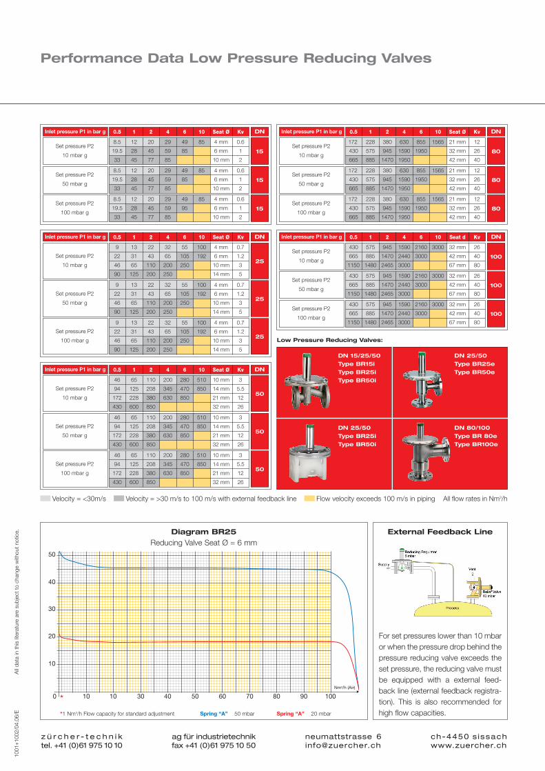
Performance Data Low Pressure Reducing Valves
8.5 12 20 29 49 85 4 mm 0.6
19.5 28 45 59 85 6 mm 1
33 45 77 85 10 mm 2
0.5 1 2 4 6 10 Seat Ø KvInlet pressure P1 in bar g
Set pressure P2
10 mbar g15
DN
Low Pressure Reducing Valves:
8.5 12 20 29 49 85 4 mm 0.6
19.5 28 45 59 85 6 mm 1
33 45 77 85 10 mm 2
Set pressure P2
50 mbar g15
8.5 12 20 29 49 85 4 mm 0.6
19.5 28 45 59 95 6 mm 1
33 45 77 85 10 mm 2
Set pressure P2
100 mbar g15
172 228 380 630 855 1565 21 mm 12
430 575 945 1590 1950 32 mm 26
665 885 1470 1950 42 mm 40
0.5 1 2 4 6 10 Seat Ø KvInlet pressure P1 in bar g
Set pressure P2
10 mbar g80
DN
172 228 380 630 855 1565 21 mm 12
430 575 945 1590 1950 32 mm 26
665 885 1470 1950 42 mm 40
Set pressure P2
50 mbar g80
172 228 380 630 855 1565 21 mm 12
430 575 945 1590 1950 32 mm 26
665 885 1470 1950 42 mm 40
Set pressure P2
100 mbar g80
430 575 945 1590 2160 3000 32 mm 26
665 885 1470 2440 3000 42 mm 40
1150 1480 2465 3000 67 mm 80
0.5 1 2 4 6 10 Seat d KvInlet pressure P1 in bar g
Set pressure P2
10 mbar g100
DN
430 575 945 1590 2160 3000 32 mm 26
665 885 1470 2440 3000 42 mm 40
1150 1480 2465 3000 67 mm 80
Set pressure P2
50 mbar g100
430 575 945 1590 2160 3000 32 mm 26
665 885 1470 2440 3000 42 mm 40
1150 1480 2465 3000 67 mm 80
Set pressure P2
100 mbar g100
Velocity = <30m/s All flow rates in Nm3/hFlow velocity exceeds 100 m/s in piping
9 13 22 32 55 100 4 mm 0.7
22 31 43 65 105 192 6 mm 1.2
46 65 110 200 250 10 mm 3
90 125 200 250 14 mm 5
0.5 1 2 4 6 10 Seat Ø KvInlet pressure P1 in bar g
Set pressure P2
10 mbar g25
DN
9 13 22 32 55 100 4 mm 0.7
22 31 43 65 105 192 6 mm 1.2
46 65 110 200 250 10 mm 3
90 125 200 250 14 mm 5
Set pressure P2
50 mbar g25
9 13 22 32 55 100 4 mm 0.7
22 31 43 65 105 192 6 mm 1.2
46 65 110 200 250 10 mm 3
90 125 200 250 14 mm 5
Set pressure P2
100 mbar g25
46 65 110 200 280 510 10 mm 3
94 125 208 345 470 850 14 mm 5.5
172 228 380 630 850 21 mm 12
430 600 850 32 mm 26
0.5 1 2 4 6 10 Seat Ø KvInlet pressure P1 in bar g
Set pressure P2
10 mbar g50
DN
46 65 110 200 280 510 10 mm 3
94 125 208 345 470 850 14 mm 5.5
172 228 380 630 850 21 mm 12
430 600 850 32 mm 26
Set pressure P2
50 mbar g50
46 65 110 200 280 510 10 mm 3
94 125 208 345 470 850 14 mm 5.5
172 228 380 630 850 21 mm 12
430 600 850 32 mm 26
Set pressure P2
100 mbar g50
DN 15/25/50
Type BR15i
Type BR25i
Type BR50i
DN 25/50
Type BR25i
Type BR50i
DN 80/100
Type BR 80e
Type BR100e
DN 25/50
Type BR25e
Type BR50e
z ü r c h e r - t e c h n i ktel. +41 (0)61 975 10 10
ag für industrietechnikfax +41 (0)61 975 10 50
ch-4450 sissachwww.zuercher.ch
neumattstrasse [email protected]
1001
+100
2/04
.06/
EA
ll da
ta in
thi
s lit
erat
ure
are
subj
ect
to c
hang
e w
ithou
t no
tice.
For set pressures lower than 10 mbaror when the pressure drop behind thepressure reducing valve exceeds theset pressure, the reducing valve mustbe equipped with a external feed-back line (external feedback registra-tion). This is also recommended forhigh flow capacities.
50
40
30
20
10
0 10 10 30 40 50 60 70 80 90 100
Nm3/h (Air)
*
Diagram BR25
Reducing Valve Seat Ø = 6 mmExternal Feedback Line
Spring “A” 50 mbar Spring “A” 20 mbar*1 Nm3/h Flow capacity for standard adjustment
Velocity = >30 m/s to 100 m/s with external feedback line
1001+1002/04.06/E_BR+BS_ROT 19.04.2006 14:16 Uhr Seite 4
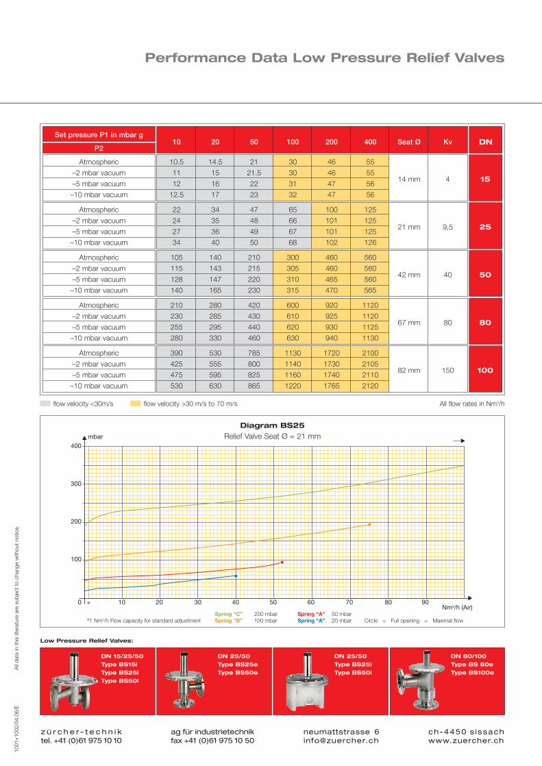
Set pressure P1 in mbar g
P210 20 50 100 200 400 Seat Ø Kv DN
Atmospheric
–2 mbar vacuum
–5 mbar vacuum
–10 mbar vacuum
10.5 14.5 21 30 46 55
11 15 21.5 30 46 5514 mm 4 15
12 16 22 31 47 56
12.5 17 23 32 47 56
Atmospheric
–2 mbar vacuum
–5 mbar vacuum
–10 mbar vacuum
22 34 47 65 100 125
24 35 48 66 101 12521 mm 9,5 25
27 36 49 67 101 125
34 40 50 68 102 126
Atmospheric
–2 mbar vacuum
–5 mbar vacuum
–10 mbar vacuum
105 140 210 300 460 560
115 143 215 305 460 56042 mm 40 50
128 147 220 310 465 560
140 165 230 315 470 565
Atmospheric
–2 mbar vacuum
–5 mbar vacuum
–10 mbar vacuum
210 280 420 600 920 1120
230 285 430 610 925 112067 mm 80 80
255 295 440 620 930 1125
280 330 460 630 940 1130
Atmospheric
–2 mbar vacuum
–5 mbar vacuum
–10 mbar vacuum
390 530 785 1130 1720 2100
425 555 800 1140 1730 210582 mm 150 100
475 595 825 1160 1740 2110
530 630 865 1220 1765 2120
Low Pressure Relief Valves:
All flow rates in Nm3/h
Performance Data Low Pressure Relief Valves
400
300
200
100
0 10 20 30 40 50 60 70 80 90Nm3/h (Air)
mbar
*
DN 15/25/50
Type BS15i
Type BS25i
Type BS50i
DN 25/50
Type BS25e
Type BS50e
DN 25/50
Type BS25i
Type BS50i
DN 80/100
Type BS 80e
Type BS100e
z ü r c h e r - t e c h n i ktel. +41 (0)61 975 10 10
ag für industrietechnikfax +41 (0)61 975 10 50
ch-4450 sissachwww.zuercher.ch
neumattstrasse [email protected]
1001
+100
2/04
.06/
EA
ll da
ta in
thi
s lit
erat
ure
are
subj
ect
to c
hang
e w
ithou
t no
tice.
Diagram BS25
Relief Valve Seat Ø = 21 mm
Spring “C” 200 mbar Spring “A” 50 mbarSpring “B” 100 mbar Spring “A” 20 mbar Circle = Full opening = Maximal flow*1 Nm3/h Flow capacity for standard adjustment
flow velocity <30m/s flow velocity >30 m/s to 70 m/s
1001+1002/04.06/E_BR+BS_ROT 19.04.2006 14:17 Uhr Seite 5

Design Features
Standard Design
Application For processes in the chemical-pharmaceutical industries, without substandard requirement.
Example of uses Protection against explosion.Prevention of building an explosive mixture of gas by exchanging the atmospheric air with an inert gas.
Mounting form Inline- and angle pattern
Surface Without special treatment
Complete drain No
Angle pattern Yes
Inline pattern No
z ü r c h e r - t e c h n i ktel. +41 (0)61 975 10 10
ag für industrietechnikfax +41 (0)61 975 10 50
ch-4450 sissachwww.zuercher.ch
neumattstrasse [email protected]
1001
+100
2/04
.06/
EA
ll da
ta in
thi
s lit
erat
ure
are
subj
ect
to c
hang
e w
ithou
t no
tice.
Sterile Design
Application Duties in the pharmaceutical industries and biotechnology with extremely high degree requirements to sterility.
Example of uses All processes and procedures in sterile quality.
Mounting form Angle pattern
Internal space Separated process- and control space, no dead space.
Surface Areas in contact with media < Ra 0.6 µm and electropolished,external electropolishing as option.
Complete drain Yes
CIP connection Yes
Clean Design
Application For procedures in the pharmaceutical industries and food production with increased requirements concerning surface treatment, dead space and cleaning.
Example of uses Protection against oxidation.The replacement of the atmospheric air by an inert gasprevents the building of an oxidizing ambiance.
Mounting form Angle pattern
Internal space Rounded edges, minimized dead space
Surface Roughness for areas in contact with media < Ra 0.6 µm,internal and external electropolishing as option.
Complete drain Yes
1001+1002/04.06/E_BR+BS_ROT 19.04.2006 14:17 Uhr Seite 6

Examples of Use
Tank Blanketing Systems
Where does blanketing take place? In all areas where in batch processes products or liquids are being handled, stored and covered with an inert atmosphere (mainly N2).How is blanketing accomplished? For optimum performance there are two pressureregulators required. A pressure reducing valve for entering the gas (inhale) and a reliefvalve for the discharging gas (exhale). Blanketing normally takes place in the pressurerange from 10 to 50 mbar. We recommend to operate the regulators adjusted andsealed, e. g. reducing valve at 15 mbar, relief valve at 40 mbar. The two function pointsshould be as far apart as possible to obtain a wide pressure spread without theconsumption of gas. As a minimum pressure spread we recommend 8 mbar. In orderto avoid the entry of oxygen into the vessel (for solvents), overpressure is necessary.In the event that no gas discharge is wanted (handling of toxic products) negativepressure must be kept.
Inerting With Overpressure / Pneumatic Transfer
Inerting means the exchange of the standard atmosphere with a non-active (inert) gasatmosphere. Behind the diaphragm of spring loaded pressure regulators atmosphericpressure exists. If the space behind the diaphragm is sealed off and charged with apilot pressure, the regulator will no longer use atmosphere as reference point but thepilot pressure (Pilot pressure design). The exchange of the gases is accelerated. If thereactor is inert, the pilot pressure is disabled and the low pressure regulators operateautomatically in the blanketing mode (see blanketing systems). Beside blanketing, this design permits different other functions such as: Inerting with overpressure,pneumatic transfer of products, blow through, blocking.
Inerting With Vacuum
If the reactor withstands vacuum, inerting can be accomplished with negative pressure. With a vacuum pump, 80 % of the standard atmosphere is sucked off, the remainingpressure is 200 mbar abs. As a result, just 20 % oxygen molecules remain in the vessel. Afterwards, the reduced volume is replaced with Nitrogen back to the pressureof 1000 mbar abs through the reducer. This dilution of the remaining oxygen (app. 1: 5 per inerting cycle) is being continued until the rest oxygen content is belowthe predetermined value. If the reactor is inert, production can start. The low pressure regulators operate automatically in the blanketing mode (see blanketingsystems).
z ü r c h e r - t e c h n i ktel. +41 (0)61 975 10 10
ag für industrietechnikfax +41 (0)61 975 10 50
ch-4450 sissachwww.zuercher.ch
neumattstrasse [email protected]
1001
+100
2/04
.06/
EA
ll da
ta in
thi
s lit
erat
ure
are
subj
ect
to c
hang
e w
ithou
t no
tice.
Reducing Valve15 mbar g
Reducing Valve15 mbar g1015 mbar g
Relief Valve40 mbar g1040 mbar g
Reducing Valve15 mbar g
Relief Valve40 mbar g
Vacuum
Pilot Pressure1000 mbar g
Relief Valve 40 mbar g
1001+1002/04.06/E_BR+BS_ROT 19.04.2006 14:18 Uhr Seite 7

z ü r c h e r - t e c h n i ktel. +41 (0)61 975 10 10
ag für industrietechnikfax +41 (0)61 975 10 50
ch-4450 sissachwww.zuercher.ch
neumattstrasse [email protected]
1001
+100
2/04
.06/
EA
ll da
ta in
thi
s lit
erat
ure
are
subj
ect
to c
hang
e w
ithou
t no
tice.
ww
w.2
becr
eativ
e.ch
For more than 50 years, the Swiss quality logo “Made in Switzerland” stands for precision and top quality. The
ZÜRCHER-TECHNIK pressure regulators have been developed and are being manufactured in Switzerland.
We do believe in the manufacturing location Switzerland, its competitive and know-how leadership.
SWISS MADE E
Zürcher-Technik develops, designs and produces pressure
regulators in Switzerland for global marketing and distribution.
The Zürcher-Technik pressure regulator knowledge, experience and
know-how is a result of more than 30 years pressure regulator
production and marketing.
The high demands and needs by the chemical-pharmaceutical
industry have led to the development of precise, corrosion resistant
and FDA conforming pressure regulators. Special attention hereby
was given to the range of blanketing applications (mixers, tanks,
centrifuges, containers, etc.)
Beside the blanketing type regulators, aseptic pressure regulators
for sterile or food service conforming processes have become an
essential part of our manufacturing program.
Zürcher-Technik welcomes competition and is happy to meet their
challenge. Our mission statement: In the long run, a company's sur-
vival and well being depends on its capability to come up with more
innovative solutions than its competitors. Quality of our service, hig-
hest level or product reliability, dependable performance and custo-
mer satisfaction represent the key portion of our daily challenge.
We also care for our environment. Using environmentally sound
working materials and processes and furthermore applying,
stringent recycling provisions is our contribution to the protection of
our living space.
Quality commitment “Made in Switzerland”
1001+1002/04.06/E_BR+BS_ROT 19.04.2006 14:18 Uhr Seite 8