tandem wall - expocrete, an oldcastle company - … wall install guide.pdf · tandem® wall system...
TRANSCRIPT

BELGARD.COM | 1
Tandem® Wall Segmental Retaining Wall System
BELGARD.COM

2 | For more information visit Belgard.com

BELGARD.COM | 3
TANDEM® WALL SYSTEM
Table of Contents
Tandem® Wall System ...........................................................................................................................4
Features & Benefits ..............................................................................................................................5
Installation Instructions .......................................................................................................................6
Design Details .......................................................................................................................................9
Geogrid Estimating Charts ................................................................................................................22

4 | For more information visit Belgard.com
Tandem® Wall System
Tandem® Wall System designed by Belgard® provides the natural appearance of chiseled stone that will complement any hardscape. The innovative, versatile system can be used to create attractive, curved or straight retaining and freestanding landscape walls. Great for use in a wide range of residential and light commercial hardscape projects.
Visit Belgard.com for more details
ASTM Standards
PropertyTest
MethodValue Units
PhysicalSpecific Gravity
ASTM D 792
.930 G/CC
Melt MassFlow Rate
ASTM D1238
20 g/10 min
MechanicalTensile
StrengthASTM D
6383,800 psi
Tensile Elongation
ASTM D 638
5.0 %
Flexural Modulus
ASTM D 790
175,000 psi
ImpactNotched Izod
ImpactASTM D
2562.0 ft.-lb./in.
ThermalDeflection
Temperature Under Load
ASTM D648
175 ºF
Small Unit Textured & Ashlar
Approx. Dimensions 7”H x 13 3⁄16”W x 2 5⁄8”D
Approx. Weight* 18 lbs.
Coverage .64 sq. ft.
Medium Unit Textured & Ashlar
Approx. Dimensions 7”H x 15 7⁄8”W x 2 5⁄8”D
Approx. Weight* 22 lbs.
Coverage .77 sq. ft.
Large Unit Textured & Ashlar
Approx. Dimensions 7”H x 18 1⁄2”W x 2 5⁄8”D
Approx. Weight* 25 lbs.
Coverage .90 sq. ft.
Tandem Cap Textured
Approx. Dimensions 3 1⁄4”H x 24”W x 15”D
Approx. Weight* 91 lbs.
Coverage 0.54 sq. ft.
DIMENSIONS
CONNECTING MEMBER PRODUCT DATA
Dovetail connection
Textured unit Ashlar unit
*Weight may vary. Please check with your local Belgard representative for exact product specifications. Above values may change with materials.
CONNECTING MEMBERS
TANDEM® WALL SYSTEM COMPONENTS
7
13 3/16"
1'-0"
7 1/16"
CONNECTOR
FRONT VENEER
BACK VENEER
Tandem Cap
8-1/87 7 /8”
6 7/8”
13 3/16”
7”
12”

BELGARD.COM | 5
Tandem® Wall SystemTANDEM® WALL SYSTEM
Features & Benefits
BENEFITS BY THE NUMBERS:
• Minimum outside radius of 6’
• Free Standing walls up to 28”
• Exceeds 5,000 PSI compressive strength concrete
• Engineered 90° corners
• Gravity walls up to 3 feet
• Reinforced walls up to 8 feet
• Panel sizes: 7” x 13 3/16” x 2 5/8” - 18 lbs./panel 7” x 15 7/8” x 2 5/8” - 22 lbs./panel 7” x 18 1/2” x 2 5/8” - 25 lbs./panel
BENEFITS OF BELGARD® TANDEM® WALL:
• Meets the material requirements of ASTM C-1372
• Classic look of natural stone
• 24 different facial textures
• Build curved or straight walls
• Free Standing
• Three color blends
• Gravity wall height up to 3 feet without surcharge and reinforced walls up to 8'
• 2.6 connectors per sq. ft. of wall
• Polypropylene Copolymer
• 2 connectors per unit
• 3 bags of connectors for every pallet of panels
CONNECTING MEMBERS
BELGARD’S CONNECTOR DESIGN CREATES STRUCTURAL INTEGRITY IN CURVED OR STRAIGHT WALLS.
Patent
Pending
6 7/8”
7 7 /8”

6 | For more information visit Belgard.com
TANDEM® WALL SYSTEM
Installation Instructions
STEP 1: Remove all surface vegetation and debris. Select the length of the wall and excavate a trench the length of the wall and approximately 12” from top of final grade. Then place a dense graded aggregate and compact to 95% standard density or modified. It's not recommended to use a pea rock or a rounded type of material on the base.
STEP 2: Place the U Start Base Block™ on the compacted gravel. Level the U Start units front to back as well as side to side. Making sure the units are fully level.
STEP 3: Assemble the Tandem® Wall units by inserting the Tandem Wall connectors into the dove tails. Make sure the front and rear panels are the same length.
STEP 4: Place the assembled Tandem® Wall unit on the top of the U Start Base Block™, making sure that the first course is centered on the base block. Check to make sure units are kept level.
BELGARD.COM | 7
TANDEM® WALL SYSTEM
Installation Instructions Scan to watchInstallation Video
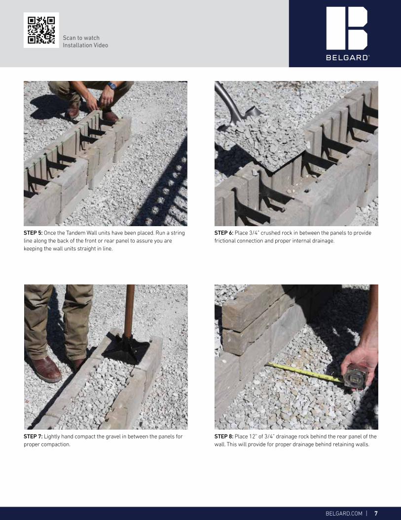
STEP 5: Once the Tandem Wall units have been placed. Run a string line along the back of the front or rear panel to assure you are keeping the wall units straight in line.
STEP 6: Place 3/4” crushed rock in between the panels to provide frictional connection and proper internal drainage.
STEP 7: Lightly hand compact the gravel in between the panels for proper compaction.
STEP 8: Place 12” of 3/4” drainage rock behind the rear panel of the wall. This will provide for proper drainage behind retaining walls.

8 | For more information visit Belgard.com
STEP 10: When placing the cap on top of Tandem® Wall, use a construction adhesive to secure the cap to the top of the wall.
STEP 9: Set additional courses of the Tandem® Wall. Making sure that you are keeping the wall in proper alignment. Backfill and compact each additional course.
TANDEM® WALL SYSTEM
Installation Instructions
STEP 11: Finished Project.
BELGARD.COM | 9
TANDEM® WALL SYSTEM
Installation Instructions1
1
2
2
3
3
4
4
5
5
6
6
7
7
8
8
A A
B B
C C
D D
TYPICAL SMALL RADIUS ASSEMBLYWEIGHT: 41 lbs
TYPICAL LARGE RADIUS ASSEMBLYWEIGHT: 48 lbs
TYPICAL CURVED RETAINING WALL WITH SETBACK
CONNECTOR 13 3/16"
7"
CONNECTOR
18 / "
1'-0"
NOTE:1-The base shall be made of starter units2-Center Tandem veneer units on starter units.3-The base foundation shall be approved by the site geotechnical engineer prior to placement of the starter units.4-Backfill is typically on site soil unless otherwise shown on the plans.
TYPICAL WALL BASE PADISOMETRIC VIEW
BACKFILLMATERIALMINIMUM 12 IN. OF # 57 STONES
BASE FOUNDATION
STARTER UNITS
DRAIN PIPE
INFILL MATERIAL#57 STONE
CORNER PANEL UNIT
TYPICAL WALL ASSEMBLY UNITFRONT PANEL
CUT PANEL
CUT PANELINSIDE
CUT PANEL
CONNECTOR2 REQUIRED PER PANEL
CROSS CONNECTORS2 REQUIRED PER PANELTURNED UPSIDE DOWN
INFILL MATERIAL#57 STONE
CONNECTOR2 REQUIRED PER PANEL
TYPICAL CURVED FREE STANDING WALL BASE SUBASSEMBLY UNITS
SEGMENTAL RETAINING WALL:
PAGE 2
1'-0"
MINIMUM RADIUS OF 6 FEET(CONCAVE & CONVEX)
7"
TYPICAL RETAINING WALL WITH 0.5” SET-BACK & 90 DEGREE CORNER
1 / "
1 / "
DETAIL CSCALE 1 / 4
TYPICAL DRAINAGE OUTLET THROUGH WALL FACE DETAIL
6 in. minimum6 in. minimum
6 in. minimum
BASE FOUNDATION
STARTER UNI TS
DRAI N PI PE
GEOTEXTI LE FABRI C(optional)
TANDEMFRONT PANEL
TANDEMCAP
TOP SOI L
UNDI STURBED SOI L
TYPICAL CROSS SECTION
TOP SOI L UNDI STURBED SOI L
4 I N. SOLID DRAI N PIPE
FRONT PANEL
BACK PANEL
TANDEM CAP
STARTER UNITS
BASE FOUNDATION
PERFORATED DRAIN PI PE
GEOGRI D
GEOTEXTI LE FABRI C(optional)
TYPICAL SECTION WITH GEOGRID
6 in. minimum
6 in.
.5 in. Setback per course
minimum6 in. minimum
12 in. minimum
FI ELD CUT FRONT OPENINGFOR OUTLET DRAI N PI PE
4" SOLI D PI PEWI TH RODENT SCREEN
4" DI AMETERPERFORATED PI PE
BACK PANELOF TANDEM WALL
4" DI AMETER TEE FI TTING
CONNECTOR2 REQUI RED PER PANEL
FRONT PANEL OF TANDEM WALL
I NFI LL # 57 STONES
12" MI N.BACKFI LL MATERI AL# 57 STONES
BACKFI LL MATERI AL#57 STONES
A
A
GEOGRID
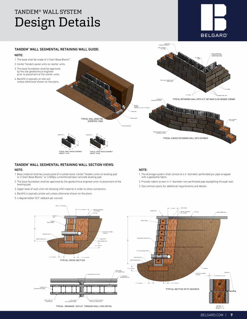
NOTE:1. The base shall be made of U Start Base Blocks™.
2. Center Tandem panel units on starter units.
3. The base foundation shall be approved by the site geotechnical engineer prior to placement of the starter units.
4. Backfill is typically on site soil unless otherwise shown on the plans.
TANDEM® WALL SEGMENTAL RETAINING WALL GUIDE:
TANDEM® WALL SYSTEM
Design Details
NOTE:1. Base material shall be constructed of crushed stone. Center Tandem units on leveling pad
or U Start Base Blocks™ or 2,000psi unreinforced lean concrete leveling pad.
2. The base foundation shall be approved by the geotechnical engineer prior to placement of the leveling pad.
3. Upper level of wall units not showing infill material in order to show connectors.
4. Backfill is typically onsite soil unless otherwise shown on the plans.
5. 4 degree batter (0.5" setback per course).
NOTE:1. The drainage system shall consist of a 4” diameter perforated pvc pipe wrapped
with a geotextile fabric.
2. Provide rodent screen in 4” diameter non-perforated pipe daylighting through wall.
3. See contract plans for additional requirements and details.
TANDEM® WALL SEGMENTAL RETAINING WALL SECTION VIEWS:

10 | For more information visit Belgard.com
TANDEM® WALL SYSTEM
Design Details (CONTINUED)
TYPICAL ABUTMENT DETAIL
TYPICAL TOP OF WALL STEPS
CONNECTOR
EXISTING FOUNDATION
GEOTEXTI LE FABRI C
12"MI NIMUM
12"MI NI MUM
I NFI LL MATERI AL#57 STONE
FRONT PANELSTANDARD FACEWI TH FI NISHED END
I NSIDE CUT FACE UNI TTO SUPPORT CORNER FACE
CUT VENEER UNITTO MAKE CORNER FACE
LOW PERMEABLESOIL
TYPICAL WALL ASSEMBLY UNI T
TANDEM CAP
CONNECTORS2 PER PANEL
U START BASE BLOCKS
U START BASE BLOCKS
TYPI CAL WALL ASSEMBLY UNI TS
6 I N. MI N.
6.00 MIN.
TYPICAL ELEVATI ON WALL WI TH SLOPE
GROUND LEVEL WI TH SLOPE
1
1
2
2
3
3
4
4
5
5
6
6
7
7
8
8
A A
B B
C C
D D
NOTE:1-The base shall be made of starting blocks2-Center Tandem face units on starting units.3-The base foundation shall be approved by the site geotechnical engineer prior to placement of the starting blocks.4-Backfill is typically on site soil unless otherwise shown on the plans.
STEP DETAIL VIEWS:
PAGE 5
TANDEM CAP
U START BASE BLOCKS
TANDEM BACK PANEL
PAVER OR SLAB
TANDEMBACK PANEL
STARTER UNIT
1-3/8
6 IN. MINIMUM
6 IN.MINIMUM
1-3/8
PAVER OR SLAB
TANDEM CAP
BASE FOUNDATION
U START BASE BLOCKS
TANDEM BACK PANEL
INFILL MATERIAL# 57 STONE
TANDEM CAP
TANDEM FRONT PANEL
TANDEM BACK PANEL
INFILL MATERIAL# 57 STONE
PAVER OR SLAB
6 MIN.
6 MINIMUM
PAVER OR SLAB
TANDEM FRONT PANEL
INFILL MATERIAL# 57 STONES
U START BASE BLOCKS
SOIL
U START BASE BLOCKS
SOIL
TANDEM CAP
BASE FOUNDATION
36 IN. MAX.
6 MIN.SOIL7 IN.
15 IN.
6 IN.MINIMUM
7 IN.
15 IN.
NOTE:Geotextile fabric shall be placed where the retaining wall abut to existing foundations as shown on the retaining wall site plans. Overlap all abutment joints 12” with minimum 24” fabric.
NOTE:1. The base shall be made of starting blocks
2. Center Tandem face units on starting units.
3. The base foundation shall be approved by the site geotechnical engineer prior to placement of the starting blocks.
4. Backfill is typically on site soil unless otherwise shown on the plans.
TANDEM® WALL SEGMENTAL RETAINING WALL TYPICAL DETAIL VIEWS:
TANDEM® WALL STEP DETAIL VIEWS:

BELGARD.COM | 11
TANDEM® WALL SYSTEM
Design Details (CONTINUED)
TANDEM® WALL SYSTEM
Design Details (CONTINUED)
G
H
J
STEPS & CORNERS
TOP VIEW OF STEPS INTEGRATED INTO WALL
STEPS
FRONTPANEL
BACK PANEL
CONNECTOR
CORNER DETAILCONNECTORS IN CORNERS ANDENDS OF WALL MUST BE FLIPPEDTO AVOID INTERFERENCE
DETAIL G TYPICAL STEP INTEGRATION
INTO WALL
USE A STONEWITH ONE LENGTH LONGER THAN FRONT PANEL
FRONT PANEL
WALL
CUT VENNER AT
DETAIL HTYPICAL CORNER WALL
BACK PANELCUT TOMATCH WITH FRONT PANELSDOVETAIL
USE A BACK PANEL WITH ONE LENGTH SHORTER THAN FRONT PANEL
TEXTURED ENDSTONE
CUT VENEERAT
CUTVENEER
AT 12"
DETAIL J TYPICAL END OF WALL
USE AN END TEXTURED STONE TOCLOSE THE END OF THE WALL PAGE 6
1234
A
B
5678
C
DD
C
B
A
8 7 6 5 4 3 2 1
G
H
J
6 ½”
6 ½”
9 ¼”
TANDEM® WALL STEPS & CORNERS:
G
H
J
STEPS & CORNERS
TOP VIEW OF STEPS INTEGRATED INTO WALL
STEPS
FRONTPANEL
BACK PANEL
CONNECTOR
CORNER DETAILCONNECTORS IN CORNERS ANDENDS OF WALL MUST BE FLIPPEDTO AVOID INTERFERENCE
DETAIL G TYPICAL STEP INTEGRATION
INTO WALL
USE A STONEWITH ONE LENGTH LONGER THAN FRONT PANEL
FRONT PANEL
WALL
CUT VENNER AT
DETAIL HTYPICAL CORNER WALL
BACK PANELCUT TOMATCH WITH FRONT PANELSDOVETAIL
USE A BACK PANEL WITH ONE LENGTH SHORTER THAN FRONT PANEL
TEXTURED ENDSTONE
CUT VENEERAT
CUTVENEER
AT 12"
DETAIL J TYPICAL END OF WALL
USE AN END TEXTURED STONE TOCLOSE THE END OF THE WALL PAGE 6
1234
A
B
5678
C
DD
C
B
A
8 7 6 5 4 3 2 1
G
H
J
6 ½”
6 ½”
9 ¼”

12 | For more information visit Belgard.com
TYPICAL STRAIGHT FREE STANDING WALL BASE PAD ISOMETRIC VIEW
STARTER UNITS
INFILL MATERIAL#57 STONE
TYPICAL WALL ASSEMBLY UNIT
BASE FOUNDATION
EXCAVATION LIMITS
EXCAVATION LIMITS
STARTER UNITS
BASE FOUNDATION
TANDEM COPING
TYPICAL CROSS SECTION VIEW
TYPICAL FREE STANDING CURVED WALL BASE PAD ISOMETRIC VIEWTO MAKE CURVES SEE SUBASSEMBLY DETAILS IN PAGE 2 UNDER TYPICAL CURVED FREE STANDING WALL BASE SUBASSEMBLY UNITS
MINIMUM RADIUS OF 6 FEET(CONCVE & CONVEX)
MAX HEIGHT OF DOUBLE FACE WALLOVER RETAINING WALL
24 in. MAX
A
28 IN.Max
6 IN. 6 IN.
12 IN.
TANDEM COPING
INFILL MATERIAL#57 STONE
STARTER UNIT
BASE FOUNDATION
TANDEM® WALL SYSTEM
Design Details
NOTE:1. Retaining Wall - 4 degree batter
(0.5" setback per course)
NOTE:1. The base foundation shall be constructed of
crushed stone or 2,000 psi unreinforced concrete or U Start Base Blocks.
2. Center Tandem panel units on starter units.
3. The base foundation shall be approved by the site geotechnical engineer prior to placement of the leveling pad.
TANDEM® WALL FREE STANDING WALLS:
TYPICAL STRAIGHT FREE STANDING WALL BASE PAD ISOMETRIC VIEW
STARTER UNITS
INFILL MATERIAL#57 STONE
TYPICAL WALL ASSEMBLY UNIT
BASE FOUNDATION
EXCAVATION LIMITS
EXCAVATION LIMITS
STARTER UNITS
BASE FOUNDATION
TANDEM COPING
TYPICAL CROSS SECTION VIEW
TYPICAL FREE STANDING CURVED WALL BASE PAD ISOMETRIC VIEWTO MAKE CURVES SEE SUBASSEMBLY DETAILS IN PAGE 2 UNDER TYPICAL CURVED FREE STANDING WALL BASE SUBASSEMBLY UNITS
MINIMUM RADIUS OF 6 FEET(CONCVE & CONVEX)
MAX HEIGHT OF DOUBLE FACE WALLOVER RETAINING WALL
24 in. MAX
A
28 IN.Max
6 IN. 6 IN.
12 IN.
TANDEM COPING
INFILL MATERIAL#57 STONE
STARTER UNIT
BASE FOUNDATION

BELGARD.COM | 13
NOTE:1. Redirect geogrid above drainage pipes as required to avoid obstructions with drainage pipes extending transversely
through the reinforced zone.
2. Reinforce the walls at the vertical obstruction as shown.
3. Backfill is typically onsite soil unless otherwise shown on the plans.
TANDEM® WALL SYSTEM
Design DetailsTANDEM® WALL SYSTEM
Design Details (CONTINUED)
1
1
2
2
3
3
4
4
5
5
6
6
7
7
8
8
A A
B B
C C
D D
TYPICAL POST DETAIL
ISOMETRIC ELEVATION
NOTE: 1. Cut through geogrid layers. 2. Fencing systems approved for use with Sleeve-it 1224R are limited to the following heights: Chain link - up to 8 ft., Privacy-up to 6 ft (wooden, PVC, metal)Pedestrian Guards; 4ft max, Post size 4 x 4 maximum. 3. Designed by others. 4. A geotextile filter fabric seperator is required between the unit drainage material and site backfill soil in any application where free wateris expected upon the wall face such as in a detention pond or along waterways where the high water level may be above the bottom of the wall.Use of filrter fabric shall extend a minimum of 1 foot above the anticipated high water level. 5. A fence, railing, guIde rail/fence or other protective barrier is typically required along the top of all walls as required by the site engineer and local codes.The choice, location, and compliance to local codes of the appropriate barrier system is the reponsibilty of the owner and its site engineer. 6. Backfill is typically onsite soil unless otherwise shown in the plans. (OPTIONAL)7. Geotextile fabric as specified by the designing engineer is shown on the back face of the walls, it is recommended to be used to prevent native soils frominfiltrating into the infill material.
SLEEVE-IT 1224R LID
FRONT SLEEVE HALF
REAR SLEEVE HALF
STRUTS
VERTICAL LEG
CANTALIVER BASE
POST DETAIL VIEWS:
PAGE 8
TANDEM CAP
FRONT PANEL
UNDISTURBED SOIL
BACKFILL#57 STONES
INFILL MATERIAL#57 STONE
CONNECTORS
SLEEVE-IT # 122R
12 IN. � X 2FT DEEP
TANDEM CAP
FRONTPANEL
INFILL MATERIAL# 57 STONE
BACK PANEL
BACKFILL# 57 STONES
UNDISTURBED SOIL
FINISHED GRADE
POST
POST
TYPICAL FENCE CROSS SECTION
CAP UNIT
3.0 FT(MINIMUM)
DEPTH VARIES
FENCE OR RAILING(DESIGNED BY OTHERS)
SLEEVE AND NON-SHRINKGROUT AROUND POSTSLEEVE INSTALLED DURINGWALL CONSTRUCTION
4°12" (MIN) OF FREE-DRAINING AGGREGATE
TANDEM™ UNIT
FILL AREA BETWEENFACING UNITS WITH
FREE-DRAININGAGGREGATE
This drawing is for illustrativepurposes only and should not beused for construction without the
signature of a registeredprofessional engineer.
Scale: Drawn by:
Date: Drawing number:
belgard.com
877-235-4273
Tandem™ Retaining Wall System
Typical Fence Cross Section
3/8" = 1'-0"
1/29/2016
SB
TDRE09
TANDEM® WALL POST DETAIL VIEWS:
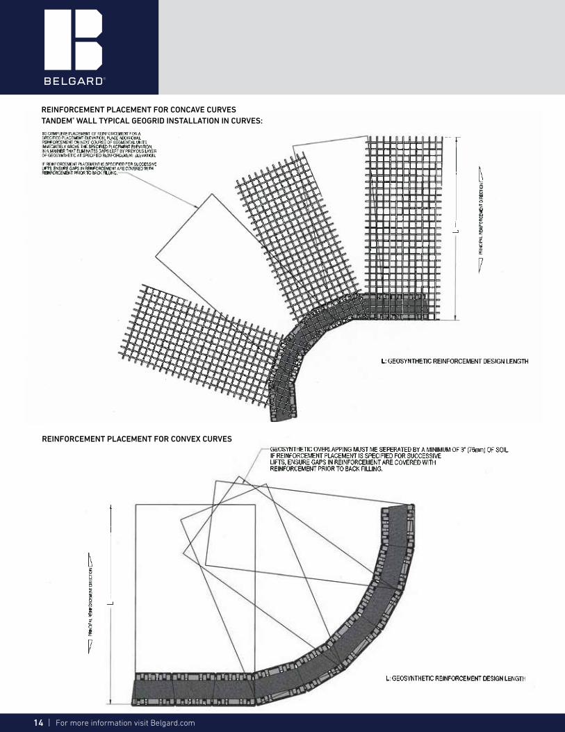
NOTE:1. Geogrid shall be placed on level backfill and extended over connector and
up to the face of the unit, pull grid taut and backfill. Stake as required.
2. Backfill is typically onsite soil unless otherwise shown on the plans.
3. Geotextile fabric as specified by the designing engineer and should be placed at the back of the stone, it is recommended to be used to prevent native soils from infiltrating into the infill material.
14 | For more information visit Belgard.com
REINFORCEMENT PLACEMENT FOR CONVEX CURVES
REINFORCEMENT PLACEMENT FOR CONCAVE CURVES TANDEM® WALL TYPICAL GEOGRID INSTALLATION IN CURVES:

BELGARD.COM | 15
REINFORCEMENT PLACEMENT FOR CONCAVE CURVES TANDEM® WALL TYPICAL GEOGRID INSTALLATION IN CORNERS:
REINFORCEMENT PLACEMENT FOR OPEN CORNERS

16 | For more information visit Belgard.com
1
1
2
2
3
3
4
4
5
5
6
6
7
7
8
8
A A
B B
C C
D D
TYPICAL WALL TREE PLANTING DETAILS:
NOTE:1- All planting offsets shall be a minimum of 2 feet + the opening diameter as measured from face of the wall 2- Lateral spacing between openings shall be a minimum of 3 times the opening diameter. 3- Soil reinforcement shall be carefully cut to avoid disturbance of adjacent reinforcement. 4- Only top two layers of reinforcement may be cut to allow planting of tree root ball. 5- Extreme care shall be taken if installing irrigation systems to not damage soil reinforcement. 6- Numbers in parenthesis are for example only.
2 ft + #1 (5 ft)
2 ft + # 2 (8 ft)
#13 ft diameter
drain pipe if required
#26 ft diameter
8 in. MINIMUMLOW PERMEABLE SOIL
REFER TOPAGE # 3
FOR WALL DETAIL
SECTION VIEW
PLAN VIEW
4 x # 1 (12ft)4 x # 2 (24ft)
3 x # 1 (9ft)
# 13 ft
3 x # 2 (18ft)4 x ( # 1 + # 2) / 2 (18ft)
2 ft + # 1 (5ft)
2 ft + # 2 (8ft)
# 26 ft
PAGE 12
1
1
2
2
3
3
4
4
5
5
6
6
7
7
8
8
A A
B B
C C
D D
TYPICAL WALL TREE PLANTING DETAILS:
NOTE:1- All planting offsets shall be a minimum of 2 feet + the opening diameter as measured from face of the wall 2- Lateral spacing between openings shall be a minimum of 3 times the opening diameter. 3- Soil reinforcement shall be carefully cut to avoid disturbance of adjacent reinforcement. 4- Only top two layers of reinforcement may be cut to allow planting of tree root ball. 5- Extreme care shall be taken if installing irrigation systems to not damage soil reinforcement. 6- Numbers in parenthesis are for example only.
2 ft + #1 (5 ft)
2 ft + # 2 (8 ft)
#13 ft diameter
drain pipe if required
#26 ft diameter
8 in. MINIMUMLOW PERMEABLE SOIL
REFER TOPAGE # 3
FOR WALL DETAIL
SECTION VIEW
PLAN VIEW
4 x # 1 (12ft)4 x # 2 (24ft)
3 x # 1 (9ft)
# 13 ft
3 x # 2 (18ft)4 x ( # 1 + # 2) / 2 (18ft)
2 ft + # 1 (5ft)
2 ft + # 2 (8ft)
# 26 ft
PAGE 12
TANDEM® WALL TYPICAL WALL TREE PLANTING DETAILS:
NOTE:1. All planting offsets shall be a minimum of 2 feet + the opening diameter as measured from face of the wall
2. Lateral spacing between openings shall be a minimum of 3 times the opening diameter.
3. Soil reinforcement shall be carefully cut to avoid disturbance of adjacent reinforcement.
4. Only top two layers of reinforcement may be cut to allow planting of tree root ball.
5. Extreme care shall be taken if installing irrigation systems to not damage soil reinforcement.
6. Numbers in parenthesis are for example only.
PLAN VIEW
SECTION VIEW

BELGARD.COM | 17
REPLACEMENT OF A BROKEN VENEER
BEFORE REPLACING THE BROKEN VENEER, REMOVE ALL THE VENEERS AND COPINGSFROM TOP OF IT IN A ''V'' SHAPE. ONCE THE AGREGATES ARE DRAINED FROM THAT SPACE, REPLACE THE BROKEN VENEERAND PUT BACK THE OTHER VENEERS BEFORE REFILLING THE WALL.
BROKEN VENEER
STARTING UNITS
VENEERS
COPING
BROKEN VENEER
VENEER TO REMOVE
COPING TO REMOVE
BROKEN VENEER REPLACEMENT
PAGE 131234
A
B
5678
C
DD
C
B
A
8 7 6 5 4 3 2 1
TANDEM® WALL BROKEN PANEL REPLACEMENT:
BEFORE REPLACING THE BROKEN VENEER, REMOVE ALL THE VENEERS AND COPINGSFROM TOP OF IT IN A ''V'' SHAPE. ONCE THE AGGREGATES ARE DRAINED FROM THAT SPACE, REPLACE THE BROKEN VENEERAND PUT BACK THE OTHER VENEERS BEFORE REFILLING THE WALL.

18 | For more information visit Belgard.com
1 Column grid
Final height: 42"
STEP 2
Place the grid on a prepared surface
Make sure the outside perimeter of the grid is clear
STEP 3
Take a panel and slide the supplied connectors into the dovetails until they snap onto the horizontal rod of the grid.
STEP 1
STEP 4
Take another stone and repeat the same process. Make sure you have a corner stone to finish the corner. Once installed, slide the stone along the horizontal axis to adjust the corner.
Connectors:
50 connectors per bag (Enough for 1-42" column)
24” x 24” Cap Unit
(Sold Separately)
Pallet of panels
21.8 square feet needed per column. Use modules G only (Lg Unit 18.5”w)
24 of the long pieces are needed (21.6 sf)
TANDEM® WALL COLUMN LAYING GUIDE:
TANDEM® COLUMN COMPONENTS
TANDEM® WALL SYSTEM
Design Details

BELGARD.COM | 19
TANDEM® WALL SYSTEM
Design Details (CONTINUED)
STEP 7
At the second row the long veneer on the column needs to be grooved. Set wall block into grooved veneer.
NOTE: You must groove a panel every other row.
STEP 7: GROOVED VENEER DETAIL
Every other row will require a grooved veneer.
OPTIONAL
STEP 6
If you have to cut the grid before installation on the base, you must cut the vertical rod at mid distance between two horizontal rods as shown below.
To integrate a wall into the column set the first course up against the column.
STEP 5
Once you have completed the first two rows, use a square to make sure the column is square and then fill the space with 3/4" clear aggregate. Fill the empty space with aggregates at every row.
TANDEM® WALL COLUMN LAYING GUIDE (CONTINUED):
STEP 8
When starting row 3 place full veneer panel across the top of grooved panel. The wall block in row 3 will butt up against column similar to row 1.
Set first wall course against the column
Row number 3 - full veneer panel
Row number 2 - grooved veneer panel
TANDEM® WALL SYSTEM
Design Details
Column Grid
Long Veneers
Grooved Veneers See detail view
Front Veneers
Front Veneers
Tandem Connectors

20 | For more information visit Belgard.com
TANDEM® WALL COLUMN LAYING GUIDE (CONTINUED):
TANDEM® WALL SYSTEM
Design Details (CONTINUED)
STEP 10
When you have reached the last row, cut the top portion of the connectors with pliers snippers or just by twisting the top portion with your hands.
STEP 9
IMPORTANTWhen you are starting the second row, make sure the base of the top panel hits the top portion of the connector.
STEP 11
Apply glue on the top of the panels before putting on the capping.
IMPORTANT: The capping must lay on the panels , not on the grid.
FINISHED WALL DETAIL
Remove connector tabs For a cap installation apply adhesive on top of veneer along entire perimeter of column
24" x 24" Capping
15" x 24" Tandem Wall Cap
Row 4 Grooved veneer course
Row 2 Grooved veneer course

BELGARD.COM | 21
Surround the post with the cage
Do the same for all the corners
Insert flat screwdriver onto clinched corner
Torque untill opening is big enough to clear vertical rod
Clinch back all the opened corners using a vise
TANDEM® WALL COLUMN AROUND A POST GUIDE:
TANDEM® WALL SYSTEM
Design Details (CONTINUED)
TANDEM® WALL SYSTEM
Design Details (CONTINUED)
STEP 2
Do the same for all the corners
STEP 1
Insert flat screwdriver onto clinched corner
Torque until opening is big enough to clear vertical rod
STEP 3
Surround the post with the cage
Clinch back all the opened corners using a vise
STEP 4
22 | For more information visit Belgard.com
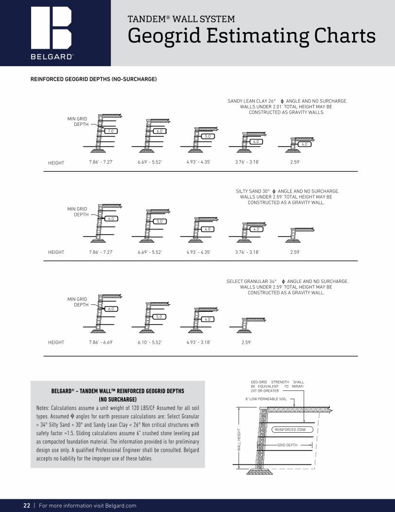
7.0' 6.0'5.0'
4.0'4.0'
WA
LL H
EIG
HT REINFORCED ZONE
GRID DEPTH
8" LOW PERMEABLE SOIL
GEO-GRID STRENGTH SHALLBE EQUIVALENT TO MIRAFI2XT OR GREATER
6.0'5.0'
4.0' 4.0'
6.0'
5.0'4.0'
SELECT GRANULAR 34° ϕ ANGLE AND NO SURCHARGE.WALLS UNDER 2.59' TOTAL HEIGHT MAY BE
CONSTRUCTED AS A GRAVITY WALL.
SILTY SAND 30° ϕ ANGLE AND NO SURCHARGE.WALLS UNDER 2.59' TOTAL HEIGHT MAY BE
CONSTRUCTED AS A GRAVITY WALL.
SANDY LEAN CLAY 26° ϕ ANGLE AND NO SURCHARGE.WALLS UNDER 2.01' TOTAL HEIGHT MAY BE
CONSTRUCTED AS GRAVITY WALLS.MIN GRID
DEPTH
MIN GRIDDEPTH
MIN GRIDDEPTH
4.93' - 4.35' 3.76' - 3.18' 2.59'7.86' - 7.27' 6.69' - 5.52'
HEIGHT
HEIGHT
HEIGHT
2.59'3.76' - 3.18'
2.59'4.93' - 3.18'7.86' - 6.69' 6.10' - 5.52'
4.93' - 4.35'7.86' - 7.27' 6.69' - 5.52'
TANDEM® WALL SYSTEM
Geogrid Estimating Charts
BELGARD® - TANDEM WALL™ REINFORCED GEOGRID DEPTHS(NO SURCHARGE)
Notes: Calculations assume a unit weight of 120 LBS/CF Assumed for all soil types. Assumed φ angles for earth pressure calculations are: Select Granular = 34º Silty Sand = 30º and Sandy Lean Clay = 26º Non critical structures with safety factor >1.5. Sliding calculations assume 6" crushed stone leveling pad as compacted foundation material. The information provided is for preliminary design use only. A qualified Professional Engineer shall be consulted. Belgard accepts no liability for the improper use of these tables.
REINFORCED GEOGRID DEPTHS (NO-SURCHARGE)

BELGARD.COM | 23
WA
LL H
EIG
HT
GEO-GRID STRENGTH SHALLBE EQUIVALENT TO MIRAFI2XT OR GREATER
REINFORCED ZONE
GRID DEPTH
250 PSF SURCHARGE3.00'MIN
7.5'
5.0'4.0'
7.0'6.0'
7.0'6.0'
5.0'4.5'
4.0'
6.0'5.0'
4.5'4.0'
4.0'
MIN GRIDDEPTH
MIN GRIDDEPTH
MIN GRIDDEPTH
HEIGHT 5.52' - 4.93' 4.35' - 3.76' 3.18' - 2.59'7.86' - 7.27' 6.69' - 6.10' 2.01'
HEIGHT
HEIGHT
2.59'
2.59'
SELECT GRANULAR 34° ϕ ANGLE AND 250 PSFSURCHARGE. WALLS UNDER 2.59' TOTAL HEIGHT MAY
BE CONSTRUCTED AS A GRAVITY WALL.
SILTY SAND 30° ϕ ANGLE AND 250 PSF SURCHARGE.WALLS UNDER 2.01' TOTAL HEIGHT MAY BE
CONSTRUCTED AS A GRAVITY WALL.
SANDY LEAN CLAY 26° ϕ ANGLE AND 250 PSFSURCHARGE. WALLS UNDER 2.01' TOTAL HEIGHT MAY
BE CONSTRUCTED AS GRAVITY WALLS.
5.52' - 4.93' 4.35' - 3.76' 3.18'7.86' - 7.27' 6.69' - 6.10'
5.52' - 4.93' 4.35' - 3.76' 3.18'7.86' - 7.27' 6.69' - 6.10'
TANDEM® WALL SYSTEM
Geogrid Estimating Charts
BELGARD® - TANDEM WALL™ REINFORCED GEOGRID DEPTHS(250 PSF LIVE LOAD)
Notes: Calculations assume a unit weight of 120 LBS/CF Assumed for all soil types. Assumed φ angles for earth pressure calculations are: Select Granular = 34º, Silty Sand= 30º and Sandy Lean Clay = 26º Non critical structures with safety factor >1.5. Sliding calculations assume 6” crushed stone leveling pad as compacted foundation material. The information provided is for preliminary design use only. A qualified Professional Engineer shall be consulted. Oldcastle accepts no liability for the improper use of these tables.
REINFORCED GEOGRID DEPTHS (250 PSF LIVE LOAD)
24 | For more information visit Belgard.com
13 MIN
WA
LL H
EIG
HT
GEO-GRID STRENGTH SHALLBE EQUIVALENT TO MIRAFI2XT OR GREATER
REINFORCED ZONE
GRID DEPTH
8" LOW PERMEABLE SOIL
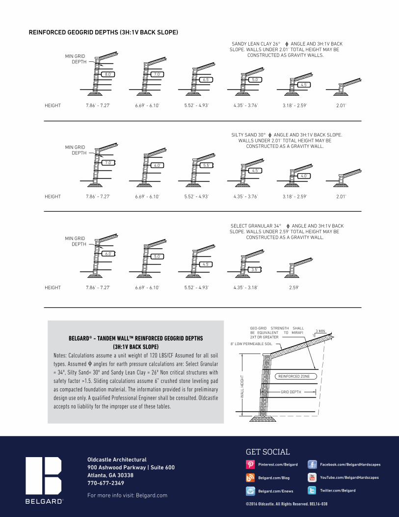
8.0'
4.5'
7.0'6.5' 5.0'
7.0'6.0' 5.5'
4.5'4.0'
6.0'5.0'
4.5'3.5'
MIN GRIDDEPTH
MIN GRIDDEPTH
MIN GRIDDEPTH
HEIGHT
HEIGHT
HEIGHT
5.52' - 4.93' 4.35' - 3.76' 3.18' - 2.59'7.86' - 7.27' 6.69' - 6.10'
2.01'
2.01'
SELECT GRANULAR 34° ϕ ANGLE AND 3H:1V BACKSLOPE. WALLS UNDER 2.59' TOTAL HEIGHT MAY BE
CONSTRUCTED AS A GRAVITY WALL.
SILTY SAND 30° ϕ ANGLE AND 3H:1V BACK SLOPE.WALLS UNDER 2.01' TOTAL HEIGHT MAY BE
CONSTRUCTED AS A GRAVITY WALL.
SANDY LEAN CLAY 26° ϕ ANGLE AND 3H:1V BACKSLOPE. WALLS UNDER 2.01' TOTAL HEIGHT MAY BE
CONSTRUCTED AS GRAVITY WALLS.
5.52' - 4.93' 4.35' - 3.76' 3.18' - 2.59'7.86' - 7.27' 6.69' - 6.10'
5.52' - 4.93' 4.35' - 3.18' 2.59'7.86' - 7.27' 6.69' - 6.10'
REINFORCED GEOGRID DEPTHS (3H:1V BACK SLOPE)
BELGARD® - TANDEM WALL™ REINFORCED GEOGRID DEPTHS(3H:1V BACK SLOPE)
Notes: Calculations assume a unit weight of 120 LBS/CF Assumed for all soil types. Assumed φ angles for earth pressure calculations are: Select Granular = 34º, Silty Sand= 30º and Sandy Lean Clay = 26º Non critical structures with safety factor >1.5. Sliding calculations assume 6” crushed stone leveling pad as compacted foundation material. The information provided is for preliminary design use only. A qualified Professional Engineer shall be consulted. Oldcastle accepts no liability for the improper use of these tables.
GET SOCIAL
©2016 Oldcastle. All Rights Reserved. BEL16-038
Facebook.com/BelgardHardscapes
Belgard.com/Enews
Belgard.com/Blog
Twitter.com/Belgard
YouTube.com/BelgardHardscapes
Pinterest.com/Belgard
For more info visit: Belgard.com
Oldcastle Architectural900 Ashwood Parkway | Suite 600 Atlanta, GA 30338 770-677-2349