tampering application for i.mx7dsabresd - nxp.com · gui application guide external tampering...
TRANSCRIPT

© 2018 NXP B.V.
Tampering Application for i.MX7Dsabresd
1. Introduction
External Tamper Detection is a special mechanism
provided through a chip pin to signal when the device
encounters unauthorized opening or tampering. This
Linux user space application is a tool that allows
tampering configuration and real time monitoring of the
most important SNVS registers.
This document provides instructions on how to setup
and run the Tampering Application on imx7dsabresd.
The document describes the steps required to software
and physical setup for both passive and active
tampering.
2. Overview
Inside the chip, when the device encounters
unauthorized opening or tampering, the received signal
is compared with the desired signal level, once unequal, tamper event is found. When the desired signal
is fixed, it is a passive tamper; when the desired signal level is also toggling with time, it is an active
tamper.
The chip supports at most 10 passive tamper detection pins, or 5 active tamper pairs alternatively.
Active tamper is used to detect tampering of an on chip wire mesh. There are 5 active tamper output ports
and 10 external tamper inputs. Any combination of active tamper output can be configured to any one of
the 10 external tamper inputs.
If the tamper detection feature is enabled by software then opening of the tamper contact will activate
security related hardware by automatic and immediate erasure of the Zeroizable Master Key.
NXP Semiconductors Document Number: AN12210
Application Note Rev. 0 , 07/2018
Contents
1. Introduction ........................................................................ 1 2. Overview ............................................................................ 1 3. Application architecture ..................................................... 2
3.1. Components ............................................................ 2 3.2. Communication Schema ......................................... 2
4. GUI Application Guide ...................................................... 3 4.1. Components ............................................................ 3 4.2. Flow ........................................................................ 5 4.3. Use case example .................................................... 6
5. Registers configuration used .............................................. 7 5.1. SNVS/Tampering registers configuration ............... 7 5.2. SNVS/Tampering registers for active tampering .... 8 5.3. SNVS/Tampering status & SRTC registers .......... 10 5.4. SNVS/ZMK registers ............................................ 12
6. Setup ................................................................................ 12 6.1. Building the Linux image ..................................... 12 6.2. Install QT Creator ................................................. 13 6.3. Build a SDK for QT Creator ................................. 13 6.4. Setup Qt Creator IDE ............................................ 14 6.5. Create a toolchain for 32 bit ARM ........................ 15 6.6. Build the tampering and ZMK application............ 16 6.7. Running tampering GUI application ..................... 17
7. Revision History .............................................................. 20
External Tampering Application for i.MX7 Dsabresd, Application Note, Rev. 0, 07/2018
2 NXP Semiconductors
3. Application architecture
3.1. Components
The application has three components:
• A tampering server that is used to configure registers to set up active/passive tampering
detection mechanism
• A ZMK server that is used to program the value of ZMK
• A GUI application that is used to command the two servers.
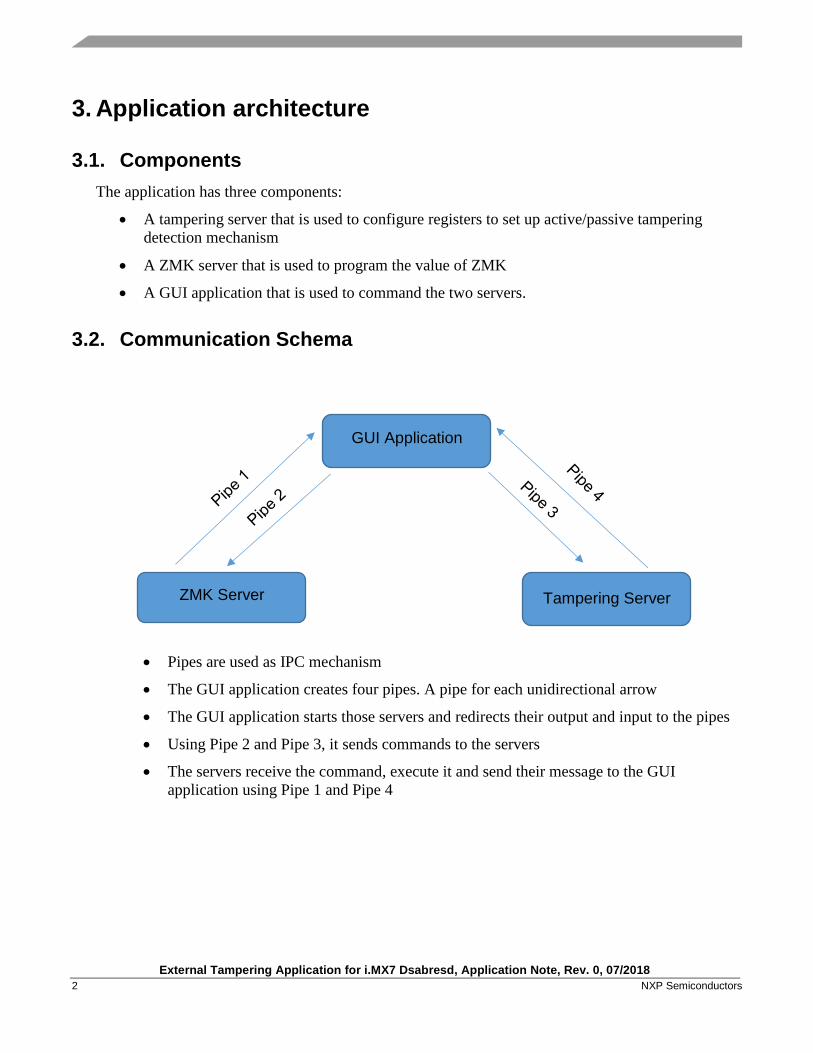
3.2. Communication Schema
• Pipes are used as IPC mechanism
• The GUI application creates four pipes. A pipe for each unidirectional arrow
• The GUI application starts those servers and redirects their output and input to the pipes
• Using Pipe 2 and Pipe 3, it sends commands to the servers
• The servers receive the command, execute it and send their message to the GUI
application using Pipe 1 and Pipe 4
GUI Application
ZMK Server Tampering Server

GUI Application Guide
External Tampering Application for i.MX7 Dsabresd, Application Note, Rev. 0, 07/2018
NXP Semiconductors 3
4. GUI Application Guide
Starting the GUI application will show the following window:
Figure 1. GUI application window
4.1. Components
The GUI application has the following components:
• A Platform drop-down menu that allows choosing a platform on which the application will
be running. Available platforms are: i.MX7D and i.MX6UL.
• A Tampering type drop-down menu that allows to choose a tampering type that will decide
which configuration should be written on the board. Available tampering types are: active
and passive for i.MX7D and passive for i.MX6UL.

External Tampering Application for i.MX7 Dsabresd, Application Note, Rev. 0, 07/2018
4 NXP Semiconductors
• An “OK” button that once pressed, the current configuration selected from Platform and
Tampering type drop-down menus will be written on the board.
• Twenty buttons that will show the current state of tampering pins
• A ZMK set value textbox that will be used to both set and show the current value of ZMK
• A log textbox that will show messages with all the changes made in application components
and in SNVS registers state.

GUI Application Guide
External Tampering Application for i.MX7 Dsabresd, Application Note, Rev. 0, 07/2018
NXP Semiconductors 5
• A Show all messages option that once selected, displays all the messages received by the
application from servers on the log text box.
4.2. Flow
Following are the required steps to use the application:
• Step 1:
Choose a platform and a tampering type from the drop-down menus.
• Step 2(Optional):
Click on the Show all messages option to see all the messages including the ones from
tampering and ZMK servers. This step can be done anytime during the runtime of the
application.
• Step 3:
Press OK to write the chosen configuration to the board. It now starts two background
threads in the GUI application that will start reading and displaying the state of tampering
and ZMK registers.
• Step 4(Optional):
Try setting the value of ZMK from the ZMK set value textbox.

External Tampering Application for i.MX7 Dsabresd, Application Note, Rev. 0, 07/2018
6 NXP Semiconductors
• Step 5:
Make physical tampering events.
4.3. Use case example
Let’s assume the scenario where the you want to use an i.MX7D board, and you want to set a passive
tampering detection on it. Following are the required steps to use the application:
• Step 0:
Power on the board and open a Terminal. After that, run the GUI application.
• Step 1:
From the Platform drop-down menu, chose i.MX7D.
From the Tampering type drop-down menu, chose Passive.
• Step 2(Optional):
Click on the Show all messages option.
• Step 3:
Click the “OK” button.
• Step 4(Optional):
Set the value of the ZMK to 0x11223344(hit Enter after writing the value).

Registers configuration used
External Tampering Application for i.MX7 Dsabresd, Application Note, Rev. 0, 07/2018
NXP Semiconductors 7
• Step 5:
Connect the line between tamper pin 1 with ground pin 1.
5. Registers configuration used
5.1. SNVS/Tampering registers configuration
SNVS_LP Tamper Glitch Filters Configuration (LPTGFCR) 44h
The SNVS_LP Tamper Glitch Filters Configuration Register is used to configure the
glitch filters for the SNVS_LP tamper inputs. This register cannot be programmed when
the LPTGFCR_SL or LPTGFCR_HL bit is set.
SNVS_LP Tamper Detectors Configuration (LPTDCR) 48h
The SNVS_LP Tamper Detectors Configuration Register is used to configure analog and
digital tamper detector sources. This register cannot be programmed when LPTDCR is
locked for write.

External Tampering Application for i.MX7 Dsabresd, Application Note, Rev. 0, 07/2018
8 NXP Semiconductors
SNVS_LP Tamper Detectors Config 2 (LPTDC2R) A0h
The SNVS_LP Tamper Detectors Configuration 2 Register is used to configure digital
external tamper sources. This register cannot be programmed when LPTDCR is locked
for write.
5.2. SNVS/Tampering registers for active tampering
SNVS_LP Active Tamper Control (LPATCTLR) E0h
The SNVS_LP Active Tamper Control Register is used to enable the LFSRs which is
used for the SNVS_LP active tamper outputs. It is also used to control external pads to
enable for input or output.
Registers configuration used
External Tampering Application for i.MX7 Dsabresd, Application Note, Rev. 0, 07/2018
NXP Semiconductors 9
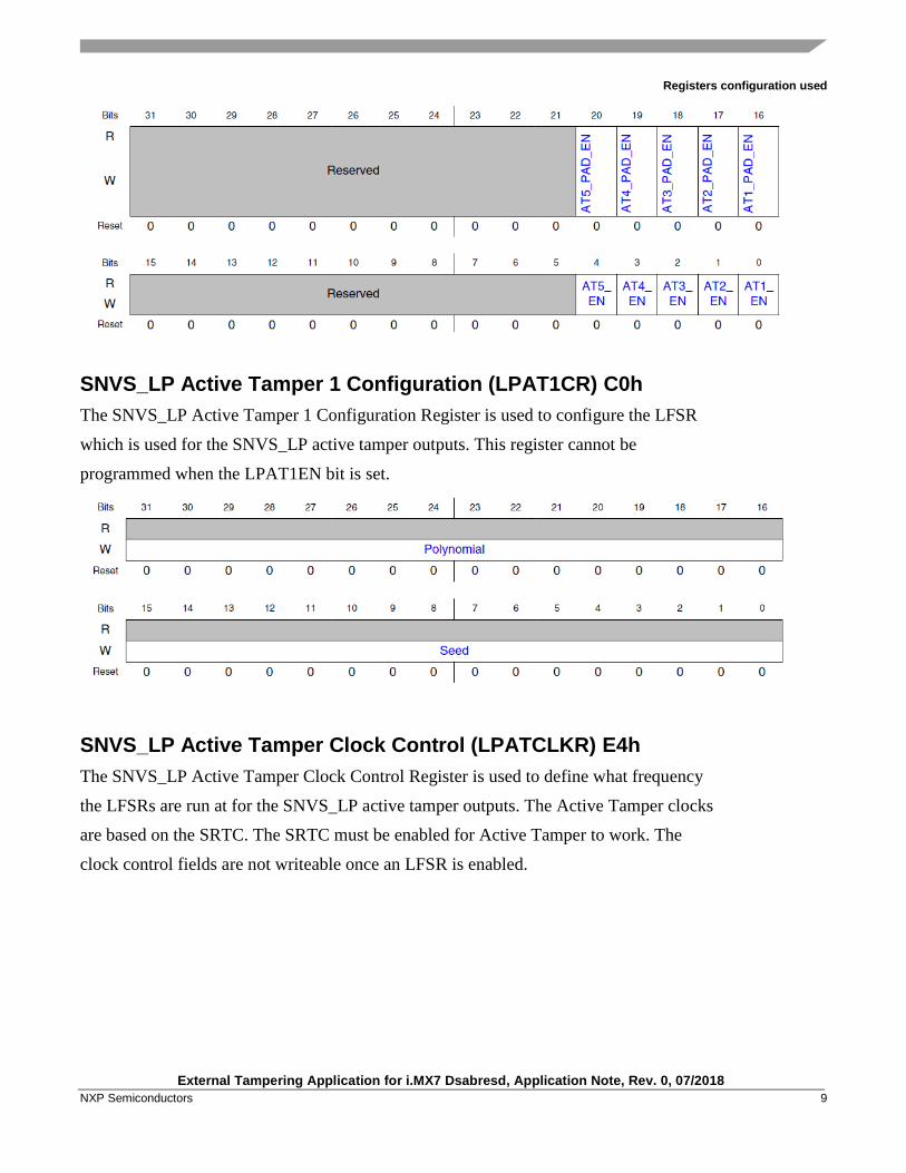
SNVS_LP Active Tamper 1 Configuration (LPAT1CR) C0h
The SNVS_LP Active Tamper 1 Configuration Register is used to configure the LFSR
which is used for the SNVS_LP active tamper outputs. This register cannot be
programmed when the LPAT1EN bit is set.
SNVS_LP Active Tamper Clock Control (LPATCLKR) E4h
The SNVS_LP Active Tamper Clock Control Register is used to define what frequency
the LFSRs are run at for the SNVS_LP active tamper outputs. The Active Tamper clocks
are based on the SRTC. The SRTC must be enabled for Active Tamper to work. The
clock control fields are not writeable once an LFSR is enabled.
External Tampering Application for i.MX7 Dsabresd, Application Note, Rev. 0, 07/2018
10 NXP Semiconductors
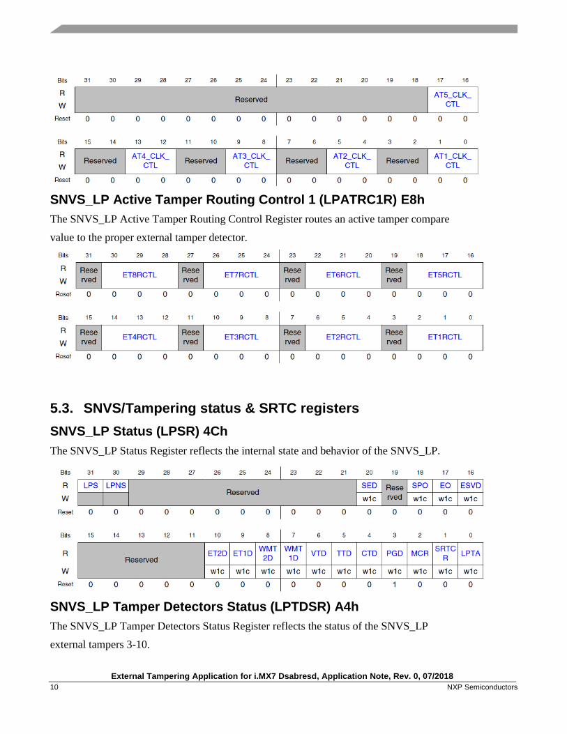
SNVS_LP Active Tamper Routing Control 1 (LPATRC1R) E8h
The SNVS_LP Active Tamper Routing Control Register routes an active tamper compare
value to the proper external tamper detector.
5.3. SNVS/Tampering status & SRTC registers
SNVS_LP Status (LPSR) 4Ch
The SNVS_LP Status Register reflects the internal state and behavior of the SNVS_LP.
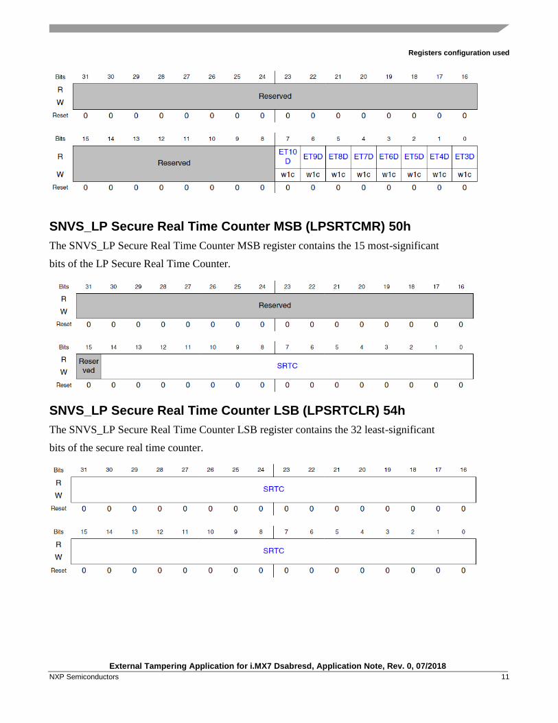
SNVS_LP Tamper Detectors Status (LPTDSR) A4h
The SNVS_LP Tamper Detectors Status Register reflects the status of the SNVS_LP
external tampers 3-10.
Registers configuration used
External Tampering Application for i.MX7 Dsabresd, Application Note, Rev. 0, 07/2018
NXP Semiconductors 11
SNVS_LP Secure Real Time Counter MSB (LPSRTCMR) 50h
The SNVS_LP Secure Real Time Counter MSB register contains the 15 most-significant
bits of the LP Secure Real Time Counter.
SNVS_LP Secure Real Time Counter LSB (LPSRTCLR) 54h
The SNVS_LP Secure Real Time Counter LSB register contains the 32 least-significant
bits of the secure real time counter.
External Tampering Application for i.MX7 Dsabresd, Application Note, Rev. 0, 07/2018
12 NXP Semiconductors
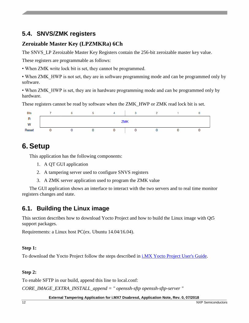
5.4. SNVS/ZMK registers
Zeroizable Master Key (LPZMKRa) 6Ch
The SNVS_LP Zeroizable Master Key Registers contain the 256-bit zeroizable master key value.
These registers are programmable as follows:
• When ZMK write lock bit is set, they cannot be programmed.
• When ZMK_HWP is not set, they are in software programming mode and can be programmed only by
software.
• When ZMK_HWP is set, they are in hardware programming mode and can be programmed only by
hardware.
These registers cannot be read by software when the ZMK_HWP or ZMK read lock bit is set.
6. Setup
This application has the following components:
1. A QT GUI application
2. A tampering server used to configure SNVS registers
3. A ZMK server application used to program the ZMK value
The GUI application shows an interface to interact with the two servers and to real time monitor
registers changes and state.
6.1. Building the Linux image
This section describes how to download Yocto Project and how to build the Linux image with Qt5
support packages.
Requirements: a Linux host PC(ex. Ubuntu 14.04/16.04).
Step 1:
To download the Yocto Project follow the steps described in i.MX Yocto Project User's Guide.
Step 2:
To enable SFTP in our build, append this line to local.conf:
CORE_IMAGE_EXTRA_INSTALL_append = " openssh-sftp openssh-sftp-server "
Setup
External Tampering Application for i.MX7 Dsabresd, Application Note, Rev. 0, 07/2018
NXP Semiconductors 13
Step 3:
To build the Linux image with Qt5 support packages and stfp, use:
$ DISTRO=fsl-imx-x11 MACHINE=imx7dsabresd source fsl-setup-release.sh -b build-x11-7d
$ bitbake fsl-image-qt5
6.2. Install QT Creator
This section describes how to download and install QT Creator.
Requirements: a Linux host PC(ex. Ubuntu 14.04/16.04).
Step 1:
To download QT Creator, go to the following website
https://www.qt.io/download and choose the Open Souce varsion.
Step 2:
To install QT Creator, use:
chmod +x qt-unified-linux-x64-3.0.2-online.run
Choose the default configuration settings with no specific version.
$ ./qt-unified-linux-x64-3.0.2-online.run
Step 3:
To install a version compatible with your kernel, use:
./MaintenanceTool
Choose the correct version. Version can be found in this file:
fsl-release-bsp/sources/meta-qt5/recipes-qt/qt5/qt5-git.inc
Version is QT_MODULE_BRANCH.
6.3. Build a SDK for QT Creator
This section describes how to build a SDK for QT Creator.
This SDK is used as a cross toolchain for i.MX7D board.
Requirements: a Linux host PC(ex. Ubuntu 14.04/16.04) and Linux Yocto sources with Qt5 support.
External Tampering Application for i.MX7 Dsabresd, Application Note, Rev. 0, 07/2018
14 NXP Semiconductors
Step 1:
Go to the build directory of your Linux Yocto, edit this file:
fsl-release-bsp/sources/meta-fsl-bsp-release/imx/meta-sdk/recipes-fsl/images/fsl-image-qt5.bb
by appending the following line:
$ inherit populate_sdk_qt5
Step 2:
Build the SDK using:
$ bitbake fsl-image-qt5 -c populate_sdk
Step 3:
Install the SDK toolchain by executing the following file:
$ ./tmp/deploy/sdk/fsl-imx-x11-glibc-x86_64-fsl-image-qt5-cortexa7hf-neon-toolchain-4.9.11-1.0.0.sh
6.4. Setup Qt Creator IDE
This section describes how to setup the QT Creator target device and how to choose the compiler and
debugger for 32 bit ARM architecture.
Requirements: A Linux host PC(ex. Ubuntu 14.04/16.04), QT Creator and a SDK for Qt5
Step 1:
To add a new Generic Device, use:
Tools -> Options -> Devices -> ADD Generic
Step 2:
To add a new c compiler, use:
Tools -> Options -> Build&Run -> Compilers -> GCC
Select the following file from your SDK install folder:
sysroots/x86_64-pokysdk-linux/usr/bin/arm-poky-linux/arm-poky-linux-gcc
Step 3:
To add a new c++ compiler, use:
Tools -> Options -> Build&Run -> Compilers -> G++
Setup
External Tampering Application for i.MX7 Dsabresd, Application Note, Rev. 0, 07/2018
NXP Semiconductors 15
Select the following file from your SDK install folder:
sysroots/x86_64-pokysdk-linux/usr/bin/arm-poky-linux/arm-poky-linux-g++
Step 4:
To add a new debugger, use:
Tools -> Options -> Build&Run -> Compilers -> GDB
Select the following file from your SDK install folder:
sysroots/x86_64-pokysdk-linux/usr/bin/arm-poky-linux/arm-poky-linux-gdb
Step 5:
To use the device added and the compilers and debugger, use:
Tools -> Options -> Build&Run -> Kit -> Select Device Type to Generic Linux Device
Choose the Device from step 1, gcc from step 2, g++ from step 3, gdb from step 4
Step 6:
To successfully run an application and deploy it to the board, setup the SDK environment by running
this script:
$ ./environment-setup-cortexa7hf-neon-poky-linux-gnueabi
The script is located in SDK install directory.
Step 7:
To complete Step 6, go to Projects, select platform for Build&Run and add the following to run
environment:
Display=:0
6.5. Create a toolchain for 32 bit ARM
This section describes how to build a toolchain used to build tampering and zmk applications.
Requirements: a Linux host PC(ex. Ubuntu 14.04/16.04), a Linux Yocto sources
Step 1:
To build a SDK, go to your Yocto build directory and use:
$ bitbake meta-toolchain
External Tampering Application for i.MX7 Dsabresd, Application Note, Rev. 0, 07/2018
16 NXP Semiconductors
Step 2:
Go to build directory and use:
$ ./tmp/deploy/sdk.fsl-imx-x11-glibc-x86_64-meta-toolchain-cortexa7hf-neon-toolchain-4.9.11-1.0.0.sh
6.6. Build the tampering and ZMK application
This section describes how to build tampering and ZMK application in order to be used by the GUI as
servers.
Requirements: a Linux host PC(ex. Ubuntu 14.04/16.04), a Toolchain for 32 bit ARM, source files for
tampering and ZMK application
Step 1:
To build the applications, go to toolchain install folder and set up the environment, use:
$ ./environment-setup-cortexa7hf-neon-poky-linux-gnueabi
Step 2:
To build tampering, go to sources folder and use:
$ make PLATFORM=IMX7D QT=y
Step 3:
To build zmk, go to sources folder and use:
$ make PLATFORM=IMX7D QT=your
Step 4:
Create the following folders on your board rootfs:
$ mkdir -p /home/root/engine/tampering
Place your tampering executable in this folder with the following name:
tamp7
Step 5:
Create the following folders on your board rootfs:
$ mkdir -p /home/root/engine/zmk
Place your zmk executable in this folder with the following name:
zmk
Setup
External Tampering Application for i.MX7 Dsabresd, Application Note, Rev. 0, 07/2018
NXP Semiconductors 17
6.7. Running tampering GUI application
This section describes how to run tampering GUI application
Requirements: a Linux host PC(ex. Ubuntu 14.04/16.04), a QT Creator and QT SDK
Step 1:
Within u-boot, override fuse word 1, bank 3 with 0x80000000.
$ fuse override 1 3 80000000
Step 2:
Build the application using the IDE. Place your executable in the following folder:
$ mkdir -p /home/root/tamper
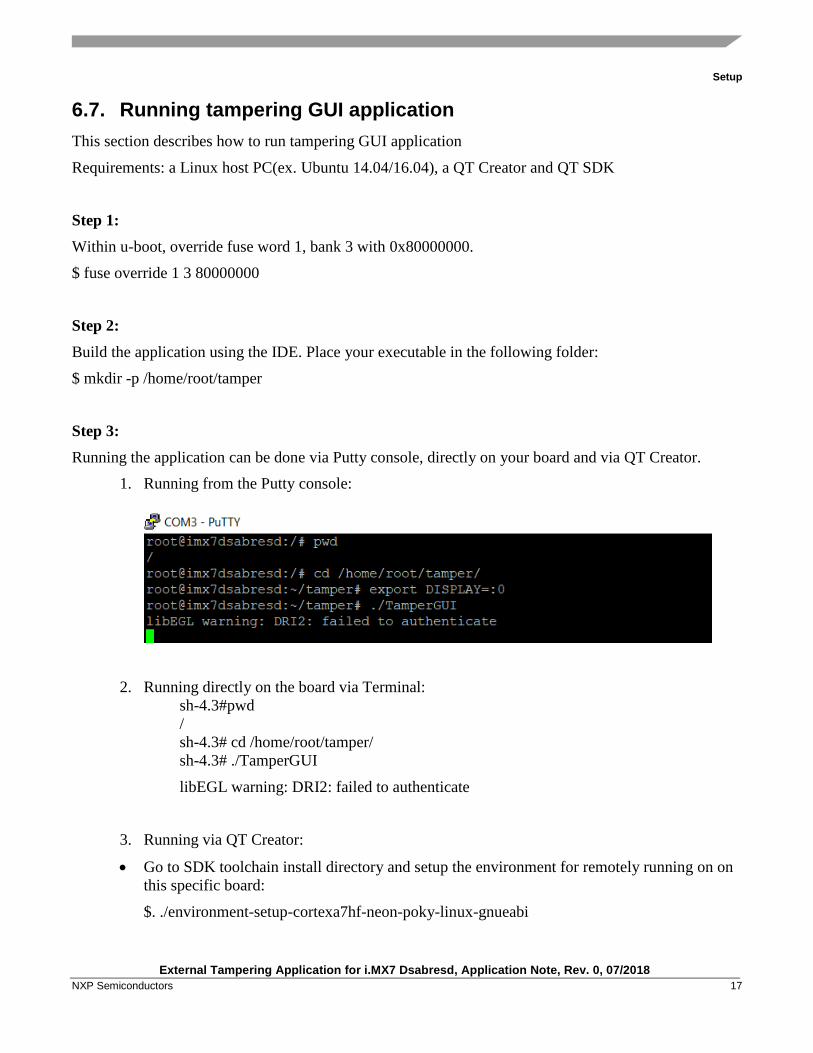
Step 3:
Running the application can be done via Putty console, directly on your board and via QT Creator.
1. Running from the Putty console:
2. Running directly on the board via Terminal:
sh-4.3#pwd
/
sh-4.3# cd /home/root/tamper/
sh-4.3# ./TamperGUI
libEGL warning: DRI2: failed to authenticate
3. Running via QT Creator:
• Go to SDK toolchain install directory and setup the environment for remotely running on on
this specific board:
$. ./environment-setup-cortexa7hf-neon-poky-linux-gnueabi
External Tampering Application for i.MX7 Dsabresd, Application Note, Rev. 0, 07/2018
18 NXP Semiconductors
• In the same terminal with environment set, goo to QT install directory and run the
application:
$ ./Tools/QtCreator/bin/qtcreator
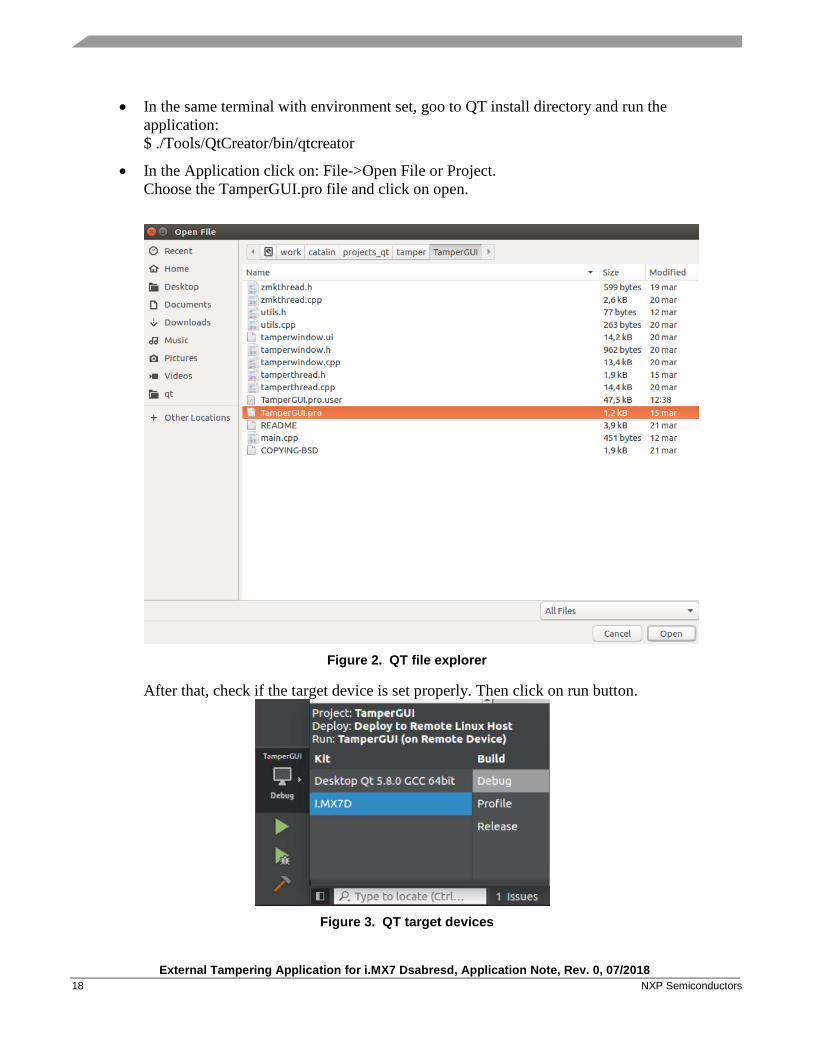
• In the Application click on: File->Open File or Project.
Choose the TamperGUI.pro file and click on open.
Figure 2. QT file explorer
After that, check if the target device is set properly. Then click on run button.
Figure 3. QT target devices
Setup
External Tampering Application for i.MX7 Dsabresd, Application Note, Rev. 0, 07/2018
NXP Semiconductors 19
External Tampering Application for i.MX7 Dsabresd, Application Note, Rev. 0, 07/2018
20 NXP Semiconductors
7. Revision History
Revision history
Revision number Date Substantive changes
0 07/2018 Initial release


How to Reach Us:
Home Page:
nxp.com
Web Support:
nxp.com/support
Information in this document is provided solely to enable system and software
implementers to use NXP products. There are no express or implied copyright licenses
granted hereunder to design or fabricate any integrated circuits based on the information
in this document. NXP reserves the right to make changes without further notice to any
products herein.
NXP makes no warranty, representation, or guarantee regarding the suitability of its
products for any particular purpose, nor does NXP assume any liability arising out of the
application or use of any product or circuit, and specifically disclaims any and all liability,
including without limitation consequential or incidental damages. “Typical” parameters
that may be provided in NXP data sheets and/or specifications can and do vary in
different applications, and actual performance may vary over time. All operating
parameters, including “typicals,” must be validated for each customer application by
customer’s technical experts. NXP does not convey any license under its patent rights
nor the rights of others. NXP sells products pursuant to standard terms and conditions of
sale, which can be found at the following address: nxp.com/SalesTermsandConditions.
While NXP has implemented advanced security features, all products may be subject to
unidentified vulnerabilities. Customers are responsible for the design and operation of
their applications and products to reduce the effect of these vulnerabilities on customer’s
applications and products, and NXP accepts no liability for any vulnerability that is
discovered. Customers should implement appropriate design and operating safeguards
to minimize the risks associated with their applications and products
NXP, the NXP logo, NXP SECURE CONNECTIONS FOR A SMARTER WORLD,
COOLFLUX, EMBRACE, GREENCHIP, HITAG, I2C BUS, ICODE, JCOP, LIFE VIBES,
MIFARE, MIFARE CLASSIC, MIFARE DESFire, MIFARE PLUS, MIFARE FLEX,
MANTIS, MIFARE ULTRALIGHT, MIFARE4MOBILE, MIGLO, NTAG, ROADLINK,
SMARTLX, SMARTMX, STARPLUG, TOPFET, TRENCHMOS, UCODE, Freescale, the
Freescale logo, AltiVec, C 5, CodeTEST, CodeWarrior, ColdFire, ColdFire+, C Ware, the
Energy Efficient Solutions logo, Kinetis, Layerscape, MagniV, mobileGT, PEG,
PowerQUICC, Processor Expert, QorIQ, QorIQ Qonverge, Ready Play, SafeAssure, the
SafeAssure logo, StarCore, Symphony, VortiQa, Vybrid, Airfast, BeeKit, BeeStack,
CoreNet, Flexis, MXC, Platform in a Package, QUICC Engine, SMARTMOS, Tower,
TurboLink, and UMEMS are trademarks of NXP B.V. All other product or service names
are the property of their respective owners. Arm, AMBA, Arm Powered, Artisan, Cortex,
Jazelle, Keil, SecurCore, Thumb, TrustZone, and μVision are registered trademarks of
Arm Limited (or its subsidiaries) in the EU and/or elsewhere. Arm7, Arm9, Arm11,
big.LITTLE, CoreLink, CoreSight, DesignStart, Mali, Mbed, NEON, POP, Sensinode,
Socrates, ULINK and Versatile are trademarks of Arm Limited (or its subsidiaries) in the
EU and/or elsewhere. All rights reserved. Oracle and Java are registered trademarks of
Oracle and/or its affiliates. The Power Architecture and Power.org word marks and the
Power and Power.org logos and related marks are trademarks and service marks
licensed by Power.org.
© 2018 NXP B.V.