tainter gate design.pdf
DESCRIPTION
design of tainter gateTRANSCRIPT

EM 1110-2-27021 Jan 00
3-1
Chapter 3Tainter Gate Design
3-1. Introduction
This chapter presents design guidance for the Corps of Engineers standard tainter gate described herein.The configuration for the standard gate has resulted from much practical and theoretical investigation ofalternatives and over 60 years of design and field experience with construction, operation, andmaintenance. It is generally the simplest and most economical tainter gate configuration for mostapplications.
3-2. Geometry, Components, and Sizing
a. Standard Corps of Engineers tainter gate geometry and components.
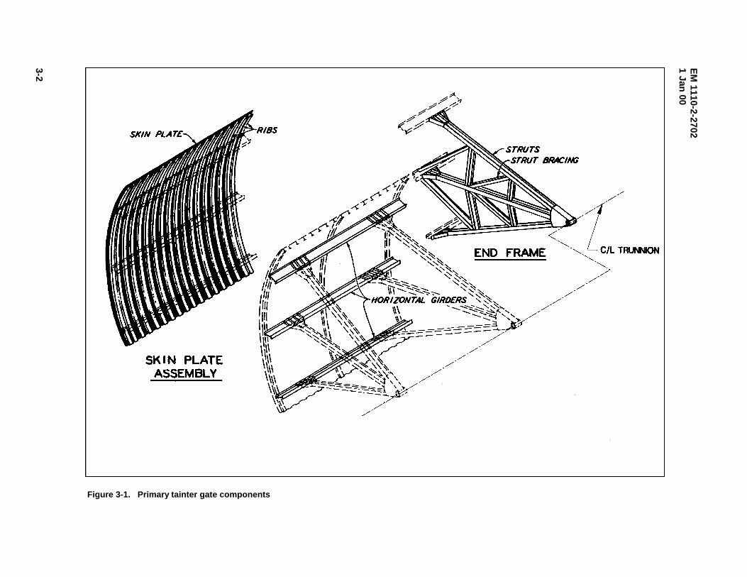
(1) Primary gate components. The principal elements of a conventional tainter gate are the skin plateassembly, horizontal girders, end frames, and trunnions (Figure 3-1). The skin plate assembly, whichforms a cylindrical damming surface, consists of a skin plate stiffened and supported by curved verticalribs. Structurally, the skin plate acts compositely with the ribs (usually structural Tee sections) to form theskin plate assembly. The skin plate assembly is supported by the horizontal girders that span the gatewidth. The downstream edge of each rib is attached to the upstream flange of the horizontal girders. Thehorizontal girders are supported by the end frames. End frames consist of radial struts or strut arms andbracing members that converge at the trunnion which is anchored to the pier through the trunnion girder. The end frames may be parallel to the face of the pier (support the horizontal girders at the ends) orinclined to the face of the pier (support the horizontal girders at some distance from the end with cantileverportions at each end). The trunnion is the hinge upon which the gate rotates. The trunnion is supported bythe trunnion girder which is addressed in Chapter 6.
(2) Other structural members. Structural bracing members are incorporated to resist specific loadsand/or to brace compression members. Certain bracing members are significant structural members, whileothers can be considered secondary members.
(a) Horizontal girder lateral bracing. Cross bracing is generally placed between adjacent girders in aplane perpendicular to the girder axes, sometimes at several locations along the length of the girders. Thishorizontal girder lateral bracing may simply provide lateral bracing for the girders or may serve to carryvertical forces from the skin plate assembly to the end frame. Lateral bracing that is located in the sameplane with the end frames is generally made up of significant structural members, while intermediatebracing located away from the end frames provides girder lateral stability and can be considered secondarymembers. The bracing located in the same plane with the end frames carries significant vertical forcesfrom the skin plate assembly to the end frame and is often considered a part of the end frame (Figure 3-2).
(b) Downstream vertical truss. The downstream vertical truss consists of bracing provided betweenthe downstream flanges of the horizontal girders. Various configurations have been used depending on thegate size and configuration as shown by Figure 3-3. For gates with more than two girders, the downstreamvertical truss does not lie in a single plane. Since the horizontal girders are arranged along the arc of theskin plate assembly, the downstream girder flanges do not lie in the same plane. Therefore,
EM
1110-2-27021 Jan
00
3-2
Figure 3-1. Primary tainter gate components

EM 1110-2-27021 Jan 00
3-3
Figure 3-2. Horizontal girder lateral bracing

EM
1110-2-27021 Jan
00
3-4
Figure 3-3. Downstream vertical truss (typical configurations)
EM 1110-2-27021 Jan 00
3-5
bracing members located between one pair of adjacent horizontal girders are not in the same plane as thosebetween the next pair. This out-of-plane geometry is commonly ignored for design purposes.
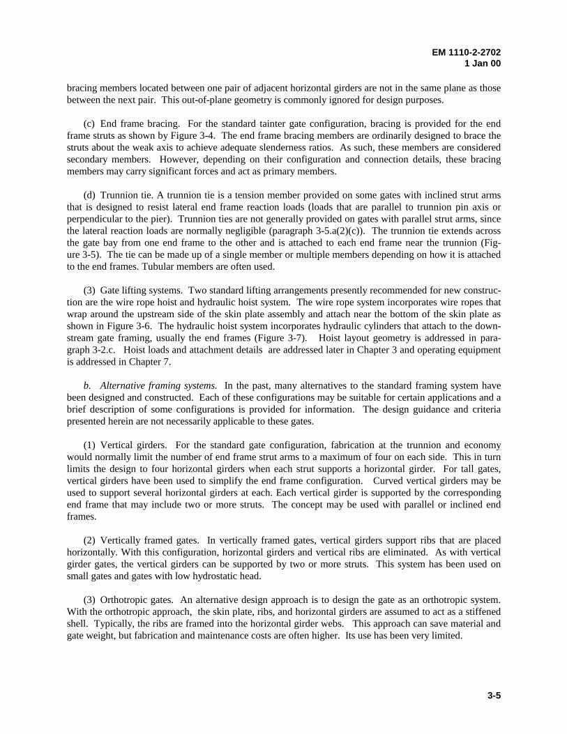
(c) End frame bracing. For the standard tainter gate configuration, bracing is provided for the endframe struts as shown by Figure 3-4. The end frame bracing members are ordinarily designed to brace thestruts about the weak axis to achieve adequate slenderness ratios. As such, these members are consideredsecondary members. However, depending on their configuration and connection details, these bracingmembers may carry significant forces and act as primary members.
(d) Trunnion tie. A trunnion tie is a tension member provided on some gates with inclined strut armsthat is designed to resist lateral end frame reaction loads (loads that are parallel to trunnion pin axis orperpendicular to the pier). Trunnion ties are not generally provided on gates with parallel strut arms, sincethe lateral reaction loads are normally negligible (paragraph 3-5.a(2)(c)). The trunnion tie extends acrossthe gate bay from one end frame to the other and is attached to each end frame near the trunnion (Fig-ure 3-5). The tie can be made up of a single member or multiple members depending on how it is attachedto the end frames. Tubular members are often used.
(3) Gate lifting systems. Two standard lifting arrangements presently recommended for new construc-tion are the wire rope hoist and hydraulic hoist system. The wire rope system incorporates wire ropes thatwrap around the upstream side of the skin plate assembly and attach near the bottom of the skin plate asshown in Figure 3-6. The hydraulic hoist system incorporates hydraulic cylinders that attach to the down-stream gate framing, usually the end frames (Figure 3-7). Hoist layout geometry is addressed in para-graph 3-2.c. Hoist loads and attachment details are addressed later in Chapter 3 and operating equipmentis addressed in Chapter 7.
b. Alternative framing systems. In the past, many alternatives to the standard framing system havebeen designed and constructed. Each of these configurations may be suitable for certain applications and abrief description of some configurations is provided for information. The design guidance and criteriapresented herein are not necessarily applicable to these gates.
(1) Vertical girders. For the standard gate configuration, fabrication at the trunnion and economywould normally limit the number of end frame strut arms to a maximum of four on each side. This in turnlimits the design to four horizontal girders when each strut supports a horizontal girder. For tall gates,vertical girders have been used to simplify the end frame configuration. Curved vertical girders may beused to support several horizontal girders at each. Each vertical girder is supported by the correspondingend frame that may include two or more struts. The concept may be used with parallel or inclined endframes.
(2) Vertically framed gates. In vertically framed gates, vertical girders support ribs that are placedhorizontally. With this configuration, horizontal girders and vertical ribs are eliminated. As with verticalgirder gates, the vertical girders can be supported by two or more struts. This system has been used onsmall gates and gates with low hydrostatic head.
(3) Orthotropic gates. An alternative design approach is to design the gate as an orthotropic system.With the orthotropic approach, the skin plate, ribs, and horizontal girders are assumed to act as a stiffenedshell. Typically, the ribs are framed into the horizontal girder webs. This approach can save material andgate weight, but fabrication and maintenance costs are often higher. Its use has been very limited.
EM 1110-2-27021 Jan 00
3-6
Figure 3-4. End frame bracing (typical arrangements)

EM 1110-2-27021 Jan 00
3-7
Figure 3-5. Trunnion tie

EM 1110-2-27021 Jan 00
3-8
(4) Stressed skin gates. Stressed skin gates are a type of orthotropic gate in which the skin plateassembly is considered to be a shell or tubular structure spanning between trunnion arms. The skin plate isstiffened with horizontal and vertical diaphragms and intermediate stiffening members (usually horizontaltee sections parallel to the intermediate or midlevel horizontal diaphragm). As with other orthotropicgates, this type of gate can save material and gate weight, but fabrication and maintenance costs are oftenhigher. (5) Truss-type or space frame gates. Three-dimensional (3-D) truss or space frame gates were some-times used in early tainter gate designs in the 1930s and 1940s. These early gates were designed as a seriestwo-dimensional (2-D) trusses and were referred to as truss-type gates. They were typically as heavy orheavier than girder designs and fabrication and maintenance costs were very high. For this reason theywere not adopted as a standard design. More recently, the use of computer designed 3-D space frame gatesconstructed with tubular sections has been investigated and may be practical in some situations.
Figure 3-6. Example of wire rope hoist system

EM 1110-2-27021 Jan 00
3-9
Figure 3-7. Hydraulically operated tainter gate
EM 1110-2-27021 Jan 00
3-10
(6) Overflow/submersible gates. These gates may be of the standard configuration but are designedto allow water to pass over the top the gate. Deflector plates are often provided on the downstream side ofthe gate to allow water and debris to pass over the framing with minimized impact. Other gates have beendesigned to include a downstream skin plate, so the gate is completely enclosed. Vibration problems havebeen prevalent with this type gate.
c. General gate sizing and layout considerations. The sizing of the gates is an important early stepin the design process. Gate size affects other project components, project cost, operation, and maintenanceof the project. The following paragraph includes various considerations that should be taken into accountwhile selecting a practical and economical tainter gate size. Related guidance can be found in EMs 1110-2-1603, 1110-2-1605, and 1110-2-2607. Appendix D provides pertinent data for a number of existingtainter gates. Each project is unique and the gate size and configuration should be determined based oncareful study of the project as a whole. The best alternative is not necessarily a gate with the lightest gateweight-to-size ratio.
(1) Gate size. The hydraulic engineer will normally establish the limiting parameters for gate heightand width. Within those limits, various height-to-width ratios should be studied to find the most suitablegate size for the project. The structural designer should coordinate closely with the hydraulic engineer indetermining the basic limiting requirements for size and shape. The size, shape, and framing system of thegates should be selected to minimize the overall cost of the spillway, rather than the gate itself. Determination of gate size will also consider practical operation and maintenance considerations specific tothe project.
(2) Gate width. The gate width will be determined based on such factors as maximum desirable widthof monoliths, length of spillway, bridge spans, drift loading, overall monolith stability, and loads ontrunnions and anchorages. On navigation projects, the gates may be set equal to the width of the lock, sothat one set of bulkheads can serve both structures. It is usually desirable to use high gates rather than lowgates for a given discharge, since the overall spillway width is reduced and results in a more economicalspillway.
(3) Gate radius. The skin plate radius will normally be set equal to or greater than the height of thegate. The radius of the gate will also be affected by operational requirements concerning clearancebetween the bottom of the gate and the water surface profile. This is often the case for navigation dams onrivers where the gate must clear the flood stage water surface profile to pass accumulated drift. On suchprojects requiring larger vertical openings, it is common to use a larger radius, up to four times the gateheight, to allow for a greater range of opening. This will require longer piers for satisfactory location ofthe trunnion girder.
(4) Trunnion location. It is generally desirable to locate the trunnion above the maximum flood watersurface profile to avoid contact with floating ice and debris and to avoid submergence of the operatingparts. However, it is sometimes practical to allow submergence for flood events, especially on navigationdams. Designs allowing submergence of 5 to 10 percent of the time are common. Gates incorporating atrunnion tie should not experience trunnion submergence. If other considerations do not control, it willusually be advantageous to locate the trunnion so that the maximum reaction is approximately horizontal tothe trunnion girder (typically about one-third the height of the gate above the sill for hydrostatic loading).This will allow for simplified design and construction by allowing the trunnion posttensioned anchorage tobe placed in horizontal layers.

EM 1110-2-27021 Jan 00
3-11
(5) Operating equipment location. The type and position of the gate lifting equipment can have asignificant effect on gate forces as the gate is moved through its range of motion. As stated previously, thetwo gate lifting systems recommended for new construction are the wire rope hoist system and the hydraulic hoist system.
(a) Wire rope hoist system. Generally, the most suitable layout for wire rope is one that minimizes theeffects of lifting forces on the gate and lifting equipment. The three possible variations in cable layoutinclude: 1) cable more than tangent to the skin plate, 2) cable tangent to the skin plate, and 3) cable lessthan tangent to the skin plate (Figure 3-8). Considering the gate and hoist system, the most idealconfiguration is when the rope is pulled vertically and is tangent to the arc of the skin plate. For thiscondition, horizontal forces exerted to the hoist equipment are insignificant, and rope contact forces actradially on the gate. A nonvertical wire rope introduces a horizontal component of force that must bebalanced by the operating equipment and associated connections. With a rope in the more-than-tangentcondition, an edge reaction force exists at the top of the skin plate due to an abrupt change in ropecurvature. This force affects the rope tension, trunnion reaction, and rib design forces. If the rope is in theless-than-tangent configuration, the rope force required to lift the gate increases exponentially as thedirection of rope becomes further from tangent. The large lifting force affects the hoist and gate. Due tovarious constraints, some compromise on location of the hoist is usually required. Many gates have non-vertical wire ropes and many gates include ropes that are nontangent at or near the full, closed and/or full,opened positions.
(b) Hydraulic cylinder hoist system. Many new gate designs utilize hydraulic cylinder hoist systemsbecause they are usually cost effective. However, these systems have some disadvantages and are notsuited for all applications. Close coordination with the mechanical design engineer is required to optimizethe hoist system. A hydraulic cylinder hoist system generally comprises two cylinders, one located at eachside of the gate. Each cylinder pivots on a trunnion mounted on the adjacent pier, and the piston rod isattached to the gate. The cylinder magnitude of force and its orientation will change continuallythroughout the range of motion. In determining the optimum cylinder position, the location of the cylindertrunnion and piston rod connection to the gate are interdependent. Generally, the piston rod connectionposition is selected and then the cylinder trunnion position is determined to minimize effects of liftingforces. For preliminary design layouts, it is often assumed that the cylinder will be at a 45-deg angle fromhorizontal when the gate is closed, although optimization studies may result in a slightly differentorientation. Generally, the most suitable location for the piston rod connection is on the gate end frame ator near the intersection of a bracing member and strut. It is preferable to have the piston rod connectionabove tailwater elevations that are consistent with the gate operating versus tailwater stage schedule;however, partial submergence may be acceptable for navigation projects. The connection locationinfluences the gate trunnion reaction forces due to simple static equilibrium. When the connection islocated upstream of the gate center of gravity, the dead load reaction at the gate trunnion will be downwardwhile the gate is lifted off the sill. However, if the connection is downstream of the center of gravity, thereaction at the gate trunnion will act upward while the gate is lifted off the sill.
(6) Other sizing considerations. The face of gate and the stop log slots should be located far enoughapart to permit the installation of maintenance scaffolding. Spillway bridge clearance is a factor indetermining the gate radius and the trunnion location. Operating clearances from the bridge and thelocation of the hoist will usually require that the sill be placed somewhat downstream from the crest, butthis distance should be as small as possible to economize on height of gate and size of pier. Additionalconsiderations could include standardization of gate sizes on a project involving multiple spillways. Thestandardization of sizes could result in savings by eliminating multiple sets of bulkheads, standardizingmachinery, and reducing stored replacement parts, etc.

EM
1110-2-27021 Jan
00
3-12
Figure 3-8. Loads due to various wire rope configurations

EM 1110-2-27021 Jan 00
3-13
3-3. Material Selection
Structural members shall be structural steel. Embedded metals, including the side and bottom seal plates,should be corrosion-resistant stainless steel. Material selection for trunnion components is discussed inChapter 4, and considerations for corrosion are discussed in Chapter 8. Table 3-1 provides a generalreference for material selection of various tainter gate components, including American Society for Testingand Materials (ASTM) standards, given normal conditions. Material selection recommendations forvarious civil works structures including tainter gates is provided by Kumar and Odeh (1989).
Table 3-1Tainter Gate Component Material Selection
Component Material Selection
Skin plate, girders, trunnion girders, lifting bracket, wear plates, end
frames
ASTM A36 or ASTM A572 Steel
Trunnion pin ASTM A705, type 630 condition H 1150 steel forging1,2
stainless steel3
ASTM A27 or A148 cast steel
Trunnion bushing ASTM B148 aluminum bronzeASTM B 22 manganese bronze or leaded
tin bronze
Self-lubricating bronze4
Trunnion hub ASTM A27 cast steelASTM A668 steel forging2
Trunnion yoke ASTM A27 cast steel
structural steel weldment
Seal plates and bolts 304 stainless steel
Lifting rope 308 stainless steel
J-seal keeper plate 410 stainless steel
galvanized steel
Posttensioning anchorage steel ASTM A772 Steel
Reinforcing steel ASTM A615 grade 60 steel
Deflector plates Ultra high molecular weight polyethylene
1 Pin may be clad with corrosion resistant steel.2 If welded, carbon content not to exceed 0.35 percent.3 Type of stainless steel should be resistant to galling and crevice corrosion.4 Use with stainless steel pin.
3-4. Design Requirements
Tainter gate structural components shall be designed based on load and resistance factor design (LRFD)principles per EM 1110-2-2105. LRFD is a method of proportioning structures such that no applicablelimit state is exceeded when the structure is subjected to all appropriate design load combinations. (SeeEM 1110-2-2105 and AISC (1994) for a more complete description of LRFD.)

EM 1110-2-27021 Jan 00
3-14
a. Design basis. The basic safety check in LRFD may be expressed mathematically as
where
Ji = load factors that account for variability in the corresponding loads
Qni = nominal load effects defined herein
D = reliability factor as defined in EM 1110-2-2105
I = resistance factor that reflects the uncertainty in the resistance for the particular limit state and, in a relative sense, the consequence of attaining the limit state.
Rn = nominal resistance.
For the appropriate limit states (paragraph 3-4.c), all structural components shall be sized such that thedesign strength DIRn is at least equal to the required strength 6JiQni. The design strength shall bedetermined as specified in paragraph 3-4.c. The required strength must be determined by structuralanalysis for the appropriate load combinations specified in paragraph 3-4.b.
b. Load requirements.
(1) Loads. Loads that are applicable to tainter gate design include gravity loads, hydrostatic loads,operating loads, ice and debris loads, and earthquake loads. Reactions are not listed below or in the loadcases. Reactions loads are not factored since they are determined from equilibrium with factored loadsapplied. As a result, reaction forces reflect the load factors of the applied loads.
(a) Gravity loads. Gravity loads include dead load or weight of the gate (D), mud weight (M), and iceweight (C), and shall be determined based on site-specific conditions.
(b) Hydrostatic loads. Hydrostatic loads consist of hydrostatic pressure on the gate considering bothupper and lower pools. Three levels of hydrostatic loads are considered. The maximum hydrostatic loadH1 is defined as the maximum net hydrostatic load that will ever occur. The design hydrostatic load H2 isthe maximum net hydrostatic load considering any flood up to a 10-year event. The normal hydrostaticload H3 is the temporal average net load from upper and lower pools, i.e., the load that exists from poollevels that are exceeded up to 50 percent of the time during the year.
(c) Gate lifting system (operating machinery) loads. Operating machinery is provided to support gatesduring lifting or lowering operations. Under normal operating conditions, the machinery provides forcesnecessary to support the gate, and for the load cases described herein, these forces are treated as reactionforces. Loads Q are machinery loads for conditions where the machinery exerts applied forces on anotherwise supported gate (paragraph 3-4.b(2)(f)). There are three levels of loads applied by the operatingmachinery to the gate. The hydraulic cylinder maximum downward load Q1 is the maximum compressivedownward load that a hydraulic hoist system can exert if the gate gets jammed while closing or when thegate comes to rest on the sill. The hydraulic cylinder at-rest load Q2 is the downward load that a hydraulic
R Q nnii DIdJ6 (3-1)
EM 1110-2-27021 Jan 00
3-15
cylinder exerts while the gate is at rest on the sill (due to cylinder pressure and the weight of the piston androd). Loads Q1 and Q2 do not exist for wire rope hoist systems. The maximum upward operatingmachinery load Q3 is the maximum upward load that can be applied by the wire rope or hydraulic hoistsystems when a gate is jammed or fully opened. The gate lifting systems exert forces on specific gatemembers whether the forces are reactions or applied loads. For example, where the wire rope bears on theskin plate, the rope exerts a contact pressure (line load) on the skin plate. The contact pressure force isequal to the rope tension force divided by the gate radius. If the wire rope is not tangent to the skin plate,the rope will exert an additional concentrated load on the gate (Figure 3-8.). Concentrated forces thattypically vary with gate position in magnitude and direction are present at the attachment points for bothgate lifting systems. Operating machinery loads must be quantified in consultation with the mechanicalengineer that designs the machinery. Determination of load magnitudes and suggested coordination arediscussed in Chapter 7.
(d) Ice-impact load I. The ice-impact load is specified to account for impact of debris (timber, ice, andother foreign objects) or lateral loading due to thermal expansion of ice sheets. Additionally, this loadprovides the overall structure with a margin of safety against collapse under barge impact. (Barge impactis an accidental event that is not practical to design for and is not specifically considered in design). I isspecified as a uniform distributed load of 73.0 KN/M (5.0 kips/ft) that acts in the downstream directionand is applied along the width of the gate at the upper pool elevation.
(e) Side-seal friction load Fs. Loads exist along the radius of the skin plate because of frictionbetween the side seals and the side-seal plate when the gate is opening or closing. The friction force perunit length along the skin plate edge dFs/dl is equal to the product of the coefficient of friction and normalforce between the seal plates and the side seals. For rubber seals, a coefficient of friction (Ps) equal to 0.5is recommended. (Seals that have Teflon rubbing surfaces provide a lower coefficient of friction and arerecommended for serviceability. However, wear of the Teflon is a concern, and applying a lowercoefficient of friction for design purposes is not recommended.) The normal force on the side seal is afunction of the preset force in the seal and the hydrostatic pressure on the surface of the seal. For normaltainter gate configurations, side-seal friction can be approximated by Equation 3-2 (Figure 3-9).
��
���
� l h + 2
h l
2
d + l S=F 21wsss ��� (3-2)
where
Ps = coefficient of side-seal friction
l = total length of the side seal
l1 = length of the side seal from the headwater to the tailwater elevations or bottom of the seal if there is no tailwater on the gate
l2 = length of the side seal from the tailwater elevation to the bottom of the seal (equals zero if there is no tailwater on the gate)
S = force per unit length induced by presetting the seal and can be approximated as

EM 1110-2-27021 Jan 00
3-16
Figure 3-9. Standard side-seal arrangement and friction load
EM 1110-2-27021 Jan 00
3-17
S = 3 EI
d 3
�, where G is the seal preset distance
Jw = unit weight of water
d = width of the J seal exposed to upper pool hydrostatic pressure (Figure 3-9)
h = vertical distance taken from the headwater surface to the tail water surface or the bottom of the seal if there is no tailwater on the gate (Figure 3-9)
(f) Trunnion pin friction loads Ft. During opening or closing of gates, friction loads exist around thesurface of the trunnion pin between the bushing and the pin and at the end of the hub between the hubbushing and side plate (yoke plate for yoke mounted pins) (Refer to Chapter 4 for description of trunnioncomponents.). These friction loads result in a trunnion friction moment Ft about the pin that must beconsidered in design. The friction moment around the pin is a function of a coefficient of friction, thetrunnion reaction force component R that acts normal to the surface of the pin (parallel to the pier face),and the radius of the pin. The friction moment at the end of the hub is a function of a coefficient offriction, the trunnion reaction force component Rz that acts normal to the end of the pin (normal to the pierface), and the average radius of the hub. The reaction forces R and Rz are discussed in para-graphs 3-5.a(2)(c) and 3-5.a(3). A coefficient of friction of 0.3 is an upper bound for design purposes.This is a conservative value that applies for any bushing material that may be slightly worn or improperlymaintained. A realistic coefficient of friction for systems with lubricated bronze or aluminum bronzebushings is 0.1 to 0.15. The designer should ensure that detailed criteria are specified in project operationsand maintenance manuals to ensure that trunnion systems are properly maintained.
(g) Earthquake design loads E. Earthquake design loads are specified based on an operational basisearthquake (OBE) with a 144-year mean recurrence interval. For gate design, the direction of earthquakeacceleration is assumed to be parallel to the gate bay centerline (i.e., it is assumed that the effects ofvertical acceleration and acceleration perpendicular to the gate bay are comparatively negligible).Earthquake forces include mass inertia forces and hydrodynamic forces of water on the structure. When atainter gate is submerged, the inertial forces due to structural weight, ice, and mud are insignificant whencompared with the hydrodynamic loads and can be ignored. For load case 1 (paragraph 3-4.b(2)(a)), thestructure is submerged, and E shall be based on inertial hydrodynamic effects of water moving with thestructure. For the structural member in question, E is determined based on the pressure that acts over thetributary area of the particular member. The hydrodynamic pressure may be estimated by Equation 3-3(Westergaard 1931). This equation applies for water on the upstream and downstream sides of thestructure.
Hy a 8
7 = p cwJ (3-3)
where
p = lateral hydrodynamic pressure at a distance y below the pool surface
Jw = unit weight of water
EM 1110-2-27021 Jan 00
3-18
H = reservoir pool depth (to bottom of dam) on upstream or downstream side of the structure
ac = maximum base acceleration of the dam due to the OBE (expressed as a fraction of gravitational acceleration)
For load case 5 (paragraph 3-4.b(2)(e)), water is not on the structure, and E is due to mass inertia forces ofthe structure, ice, and mud.
Wa = E MC,D,c (3-4)
where
WD,C,M = weight of the portion of the structure, ice, and mud that are supported by the member in question.
(h) Wave load WA. Wave loads are site specific and should be determined in consultation with theproject hydraulic engineer. Guidance on development of wave loading is provided in the Shore ProtectionManual (1984).
(i) Wind load W. Wind loads are site specific and should be calculated in accordance with ASCE(1995) but not more than 2.4 KPa (50 psf). Wind loads are small when compared to hydrostatic loads andonly affect gate reactions when the gate is in an open position.
(2) Load cases. Tainter gates shall be designed considering the strength requirements for each of thefollowing load cases and corresponding load combinations. The most unfavorable effect on various gatecomponents may occur when one or more of the loads in a particular load combination is equal to zero.Various conditions are described for the cases of gate in the closed position (load case 1), gate operating(load case 2 and load case 3), gate jammed (load case 4), and gate fully opened (load case 5). Theoperating machinery may include forces in each load case; however, these forces are treated as gate reac-tions in some cases. As a result, the load Q does not appear in some load cases (paragraph 3-4.b(2)(f)).
(a) Load case 1: Gate closed. Load combinations for this load case (Equations 3-5, 3-6, and 3-7)apply when the gate is in the closed position.
1.4 H + 1.2D + 1.6(C + M) + 1.2 Q1 2 (3-5)
]I)kQ.( or )1.2WQ.( or Q1.2[ + M)+1.6(C + 1.2D + H1.4 IA12 �� 22 2121 (3-6)
1.2 H + 1.2D + 1.6(C+ M) + 1.0E3 (3-7)
1) Extreme pool condition. Equation 3-5 describes the condition where the maximum hydrostaticload H1 is applied, gravity loads D, C, and M exist, and the hydraulic cylinders exert the at-rest load Q2.(For gates with wire rope hoists, Q2 does not exist.) It is assumed that the likelihood of the simultaneousoccurrence of H1 and WA or I or E is negligible.
2) Operating pool condition. Equation 3-6 describes the condition for which the moderate hydro-static load H2 acts in combination with Q1 or WA or I. Gravity loads D, C, and M always exist, and it isassumed that Q1, WA, and I will not occur at the same time. The load Q2 will likely always exist with W or
EM 1110-2-27021 Jan 00
3-19
I. The I load factor kI shall be equal to 1.6 when considering ice load due to thermal expansion and 1.0when considering impact of debris.
3) Earthquake condition. Equation 3-7 describes the condition where the normal hydrostatic load H3
acts in combination with earthquake loading E and gravity loads D, C, and M exist.
(b) Load case 2: Gate operating with two hoists. Load combinations for this load case (Equations 3-8and 3-9) represent the condition when the gate is opening or closing with both hoists functional. Operatingmachinery loads Q are not listed in these load combinations, because it is assumed that the hoists are gatesupports that will include reaction forces (paragraph 3-4.b(2)(f)). This load case does not include Ebecause it is assumed that the likelihood of opening or closing the gate at the same time an earthquakeoccurs is negligible. Effects on members forces should be checked considering the entire operating range(any position between the sill and the upper gate stops) for gates either opening or closing.
1.4 H + 1.2D + 1.6(C+ M) + 1.4 F + 1.0 F1 S t (3-8)
1.4 H + 1.2D + 1.6(C+ M) + 1.4 F + 1.0 F + (1.2W or k I)2 S t A I (3-9)
1) Extreme pool condition. Equation 3-8 (similar to Equation 3-5) describes the condition where themaximum hydrostatic load H1 is applied, gravity loads D, C, and M exist, and friction loads Fs and Ft existdue to gate motion. It is assumed that the likelihood of the simultaneous occurrence of H1 and WA or I or Eis negligible.
2) Operating pool condition. Equation 3-9 (similar to Equation 3-6) describes the condition forwhich the moderate hydrostatic load H2 acts in combination with WA or I. Gravity loads D, C, and M exist,and due to gate motion, friction loads Fs and Ft are applied. In the determination of H2, the lower poolelevation will include a hydrodynamic reduction due to flow of water under the gate. The magnitude ofhydrodynamic reduction should be determined in consultation with the project hydraulic engineer. Asdescribed for Equation 3-6, kI shall be equal to 1.6 for ice and 1.0 for debris.
(c) Load case 3: Gate operating with one hoist. The load combination described by Equation 3-10applies for the case where the gate is operated with only one hoist (subsequent to failure of the other hoist). Effects on members forces should be checked for all gate positions throughout the operating range for thegate either opening or closing.
1.4 H + 1.2D + 1.6(C+ M) + 1.4 F + 1.0 F2 S t (3-10)
For this case, the moderate hydrostatic load H2 is applied, gravity loads D, C, and M exist, and frictionloads Fs and Ft exist due to gate motion. In the determination of H2, the lower pool elevation will include ahydrodynamic reduction due to flow of water under the gate (must be coordinated with the projecthydraulic engineer). The effects of H1, WA, I, or E are not considered for this load case, since it isassumed that the likelihood of the simultaneous occurrence one of these loads and the failure of one hoistis negligible. Design considerations for this condition are provided in paragraph 3-5.e and serviceabilityconsiderations are discussed in paragraph 3-6.b(1).
(d) Load case 4: Gate jammed. The load combination of Equation 3-11 accounts for the possiblecondition where one hoist fails, and the gate becomes jammed between piers due to twist of the gate (suchthat one end frame is higher than the other). Effects on members forces should be checked with the gatejammed at positions throughout the operating range.
EM 1110-2-27021 Jan 00
3-20
)Q1.2or Q(1.2 + M)+1.6(C + 1.2D + H1.4 132 (3-11)
For this case, the moderate hydrostatic load H2 is applied in combination with the maximum machineryload Q3 (for wire rope hoists or hydraulic hoists) or Q1 (for hydraulic hoists), and gravity loads D, C, andM exist. It is assumed that only one hoist is functional. In the determination of H2, the lower poolelevation will include a hydrodynamic reduction due to flow of water under the gate (must be coordinatedwith the project hydraulic engineer). The effects of H1, WA, I, or E are not considered for this load case,since it is assumed that the likelihood of the simultaneous occurrence one of these loads while the gate isjammed is negligible.
(e) Load case 5: Gate fully opened. The load combination of Equation 3-12 accounts for the condi-tion where the gate is fully opened (raised to the gate stops) with wind, earthquake, or operating equipmentloads.
D 3k D + 1.6(C + M) + (1.3W or 1.0E or 1.2 Q ) (3-12)
For this case, it is assumed that the gate is raised above the pool, so effects of H, WA, and I are notincluded. Effects of Q3 oppose gravity load effects, and effects of W or E may add to or oppose gravityload effects. When Q3 is considered, or when effects W or E oppose those of gravity, C and M should beequal to 0 and the load factor kD is equal to 0.9. When the direction of W or E is such that their effectincreases gravity load effects, kD is equal to 1.2 and C and M should be considered.
(f) Assumptions on support or loading of gate lifting systems (operating machinery). The loadcombinations included herein were developed for gate design based on various assumptions on loading andsupport conditions. (See Chapter 7 for discussion on criteria regarding load and operational requirementsfor operating machinery.) These assumptions must be considered in structural analysis of gate components(paragraph 3-5). For a tainter gate to be stable, rotational restraint must be provided by a suitable support. It is assumed that this support is the sill when the gate is closed (case 1), the hoists when the gate isoperated (case 2 and case 3), the pier or some obstruction at the gate sides when the gate is jammed(case 4), and the hoists or the gate stops when the gate is fully opened (case 5). In load cases 2, 3, andsome applications of 5, operating machinery loads Q are not included, since for these cases, the hoists aresupports. The hoists provide reaction forces which are a function of all other gate loads. In load cases 1,4, and some applications of 5, where the gate is supported by something other than the hoists, any forceexerted by the hoists is an external load on the gate Q.
c. Limit states and design strength for individual members. EM 1110-2-2105 requires that strengthand serviceability limit states be considered in the design of tainter gate structural components. Strengthlimit states include general yielding, instability, fatigue, and fracture. The design strength for eachapplicable limit state DIRn is calculated as the nominal strength Rn, multiplied by a resistance factor I anda reliability factor D. Except as modified herein, limit states, nominal strength Rn, and resistance factors Ishall be in accordance with AISC (1994). For normal conditions, D shall be equal to 0.9. For gates thatare normally submerged and whose removal would disrupt the entire project, or for gates in brackish wateror sea water, D shall be equal to 0.85. Fatigue and fracture design requirements are included in para-graph 3-8 and EM 1110-2-2105. Serviceability requirements for tainter gates are specified in para-graph 3-6. The following paragraphs provide specific guidance for the design of skin plate, ribs, girders,and end frame members.
(1) Skin plate. The skin plate shall be sized such that the maximum calculated stress is less than theyield limit state of DIbFy. In determining the required strength, all load cases in paragraph 3-4.b shall be

EM 1110-2-27021 Jan 00
3-21
considered; however, the ice-impact load I may be set equal to zero at the designer’s option. This isfrequently done, with the intent of allowing local damage to the skin plate for very infrequent loadingevents rather than increasing the gate weight.
(2) Rib members. Ribs shall be sized such that the maximum calculated moment Mu is less than thenominal bending strength of DIbMn. In determining the required strength Mu, all load cases in para-graph 3-4.b shall be considered. For load cases 2, 3, and 4, the maximum effect will normally occurassuming that the gate is near the closed position.
(3) Girders. Girders shall be designed as beams or plate girders in accordance with AISC (1994). Indetermining the required strength, all load cases in paragraph 3-4.b shall be considered. For load cases 2,3, and 4, the maximum effect will normally occur assuming that the gate is near the closed position.
(4) End frame. Struts and bracing members shall be designed as members under combined forces inaccordance with AISC (1994). For gates not braced against side sway, struts shall be sized to avoid sidesway frame buckling (lateral buckling of gate toward pier face, see paragraph 3-5.a(2)). In determining therequired strength, all load cases in paragraph 3-4.b shall be considered.
(5) Secondary bracing members. The minimum axial design load in all bracing members shall be2 percent of the total axial compression force or of the flexural compressive force in the compressionflange of the corresponding braced member. Trunnion hub flange plates shall have adequate designstrength to resist the required flexural and axial loads between the struts and the trunnion hub.
3-5. Analysis and Design Considerations
This paragraph includes guidance on design of tainter gate structural components (Chapters 4 through 6provide guidance for the design of the trunnion and trunnion girder). The design and behavior of indi-vidual structural components are interrelated. The gate design should be optimized to achieve the mosteconomical design overall, not necessarily to provide the most efficient geometry and member sections foreach component. A large percentage of total gate cost is associated with the fabrication of the skin plateassembly. Therefore, the design process should be tailored to minimize the cost of the skin plate assemblyconsidering the most normal load conditions. The required strength (design forces) and deflections for allstructural components must be determined by structural analysis. Three-dimensional (3-D) analyses ormore approximate (generally conservative) two-dimensional (2-D) analyses may be conducted. Allanalytical models must include boundary conditions that are consistent with load requirements specified inparagraph 3-4.b. Paragraph 3-5.a includes a description of acceptable 2-D models (various modeling alter-natives exist), and the remainder of paragraph 3-5 provides general design considerations.
a. Two-dimensional analytical models. In the design of tainter gate structural members, it has beencommon practice to model the 3-D behavior with several independent 2-D models. With the 2-Dapproach, the overall behavior is simulated by modeling separately the behavior of the skin plate assembly(composed of the skin plate and supporting ribs), horizontal girder frames (composed of a horizontal girderand the two adjacent struts), vertical end frames (composed of struts and braces), and the verticaldownstream truss. Analysis of the 2-D models is interdependent. Various loads on one model can bereactions from another (girder frame loads are obtained from the rib model reactions), and many of thesame loads are applied to each model. Additionally, struts include member forces from separate models(the strong axis flexural behavior of the struts is simulated with the girder frame model, and axial and weakaxis flexural forces are provided by the end frame model). An alternative for each 2-D model is describedin the following subsections. In the discussion for each model, loads for all load conditions are described.

EM 1110-2-27021 Jan 00
3-22
For design analysis, load combinations and associated load factors should be applied accordingly. Variousloads that are applied to the models (such as the gate reaction loads including sill load RS and the wire ropepressure load RQ/r) are not factored, since they are a function of other factored loads.
(1) Skin plate assembly. For the 2-D approximate model, the skin plate and ribs are assumed to havezero curvature. The skin plate serves two functions. First, each unit width of skin plate is assumed to actas a continuous beam spanning the ribs in the horizontal direction (Figure 3-10). Second, the skin plateacts as the upstream flange of the ribs. The ribs, with the skin plate flange, are continuous vertical beamsthat are supported by the horizontal girders (Figure 3-11). A portion of the skin plate is considered to actas the upstream flange of the rib (paragraph 3-5.b(2)).
(a) Boundary conditions. Boundary conditions consist of simple supports located at each rib for theskin plate and at each girder for the rib members.
(b) Loads. Loading on the skin plate assembly consists of various combinations of factored loads andgate reaction loads. Factored loads consist of 1.2H or 1.4H, 1.2 WA, 1.0E, kII, and 1.2Q3/r, and gatereaction loads include Rs and RQ/r. H, WA, E, I, and Q3 are defined in paragraph 3-4.b, r is the gate radius,Rs is the sill reaction load at the bottom of the skin plate (load case 1 gate closed), and RQ is the wire ropereaction load (for load cases 2 and 3 for gates with a wire rope hoist). The factored loads shall be appliedin accordance with paragraph 3-4.b(2). Gate reaction loads RS and RQ/r are determined by equilibrium ofthe end frame model for each appropriate load condition (paragraph 3-5.a(3)) and are not factored sincethey are a function of other factored loads. For skin plate design, loads are determined based on a unitwidth of plate, and it is not considered necessary to include I and RS. For the rib model, the magnitude forloads is determined based on the tributary area of the rib. For each rib, the tributary portion of RS isresolved into a radial component that is applied as a concentrated load at the end of the rib cantilever, and atangential component that is applied as an axial force. Although not applied directly, all loads described inparagraph 3-4.b can affect rib member forces, since the reaction forces at the sill or under the wire ropeinclude the effects of trunnion friction Ft, hydraulic machinery loads Q1 and Q2, and gravity loads C, M,and D as defined in paragraph 3-4.b.
(c) Results. Analysis of the skin plate model will yield the calculated stresses and out-of-planedeflections necessary to size the skin plate in accordance with paragraphs 3-4.c(1) and 3-6. Analysis of therib model yields the calculated moments necessary for rib design in accordance with paragraph 3-4.c andreactions are the girder loading for the girder frame model.
(2) Girder frame model. The 2-D analytical model is a single-story frame consisting of beammembers that simulate the horizontal girder and two columns that represent the corresponding end framestruts (Figure 3-12). The strong axes of the struts are oriented to resist flexural forces in the plane of theframe. The model shown in Figure 3-12a applies for all load cases described in paragraph 3-4.b exceptthe unsymmetric load cases 3 and 4. For these cases, the analytical model should include applied loadswith an imposed lateral displacement to represent side sway of the frame (Figure 3-12b). For load case 3,the lateral displacement should be consistent with the expected displacement as determined by anappropriate analysis (paragraph 3-5.e). For load case 4, the maximum displacement (lateral displacementto the pier face) should be applied. For all load cases except load case 4, the frame is not braced againstside sway and the analysis should be conducted accordingly (AISC (1994), Chapter C). For load case 4,the frame can be assumed to be braced with the maximum displacement applied.
(a) Boundary conditions. The supports for the structure are at the bottom of the columns or struts andshould be modeled to simulate actual conditions. Where cylindrical pins are used at the trunnion, a fixed

EM 1110-2-27021 Jan 00
3-23
Figure 3-10. Skin plate 2-D design model

EM 1110-2-27021 Jan 00
3-24
Figure 3-11. Skin plate assembly with ribs (2-D design model)

EM 1110-2-27021 Jan 00
3-25
Figure 3-12. Girder model loads and boundary conditions

EM 1110-2-27021 Jan 00
3-26
support should be assumed and where spherical bearings are used at the trunnion, a pinned support shouldbe assumed.
(b) Loads. The girders support the skin plate assembly and loads to the girder are applied through theribs. Therefore, for each load combination, girder loading is based on reaction forces from the rib model. A uniformly distributed load equivalent to the rib reactions distributed over each tributary area is appliedalong the length of the girder. This distributed load does not require a load factor, since the rib reactionsare a function of factored loads. For gates with wire rope hoists, a concentrated load equal to the reactionfor the rib that supports the wire rope should be applied to the girder at the corresponding rib location. Theconcentrated load is due to a distributed rib load equal to 1.2Q/r for load cases 4 and 5 or RQ/r for loadcases 2 and 3 (RQ is determined by the end frame model described in paragraph 3-5.a(3)). For hydraulichoists, the cylinder force load should be applied at the cylinder connection location (for most cases on thestrut near the girder). This force is equal to 1.2Q for load cases 1, 4, and 5 or the cylinder force asdetermined by the end frame model analysis for load cases 2 and 3. All loads described in paragraph 3-4.baffect the girder frame member forces since components of each load are transferred through the ribs. It isassumed that girder lateral bracing resists girder torsional forces that are caused by gravity loads.
(c) Results. The girder frame analysis results include all design forces and deflections for the girder,flexural design forces about strong axis of the struts, and reactions that simulate lateral thrust Rz into thepier and moment at the trunnion My (Figure 3-12). The lateral thrust force Rz induces friction forces thatare a component of trunnion friction moment Ft as discussed in paragraph 3-4.b(1)(f). The effect of Rz onFT should be considered in the analysis of the end frame model. For gates with parallel end frames, theeffect of Rz may be negligible. However, Rz is more significant for gates with inclined end frames, since Rz
includes a component of the strut axial loads.
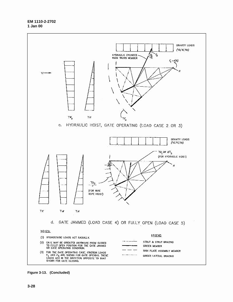
(3) End frame model. The analytical model for the end frame consists of elements to simulate strutsand strut bracing, girders (webs), girder lateral bracing, and the skin plate assembly (Figure 3-13). Strutsare modeled with frame elements, and bracing members are modeled with either frame or truss elements tobe consistent with connection details. The elements that represent the skin plate assembly and girder websare included in the model only to transfer loads and to maintain correct geometry. These elements shouldbe relatively stiff compared to other elements. The girder members should be simulated by truss elementsso the girder lateral bracing elements resist all forces transverse to the girder. (This will ensure thatbracing is proportioned so that girder torsion is limited.) The assumed boundary conditions, loading, andmodel geometry are shown by Figure 3-13 for: a) gate closed (load case 1); b) gate operating with wirerope hoist (load cases 2 and 3); c) gate operating with hydraulic cylinder hoist (load cases 2 and 3); andd) gate jammed (load case 4) or raised to stops (load case 5). Boundary conditions and loading describedin the following paragraphs are based on assumptions discussed in paragraph 3-4.b(2). The purpose of theend frame model is: a) to determine the sill reaction load RS, operating machinery reaction load RQ, andtrunnion reaction R; and b) to determine end frame member design forces.
(a) Boundary conditions. For each model described by Figure 3-13, the trunnion is modeled as a pinfree to rotate with no translation. For the gate-closed case, the boundary conditions for gates with wirerope or hydraulic hoists are identical as shown by Figure 3-13a. The gate is supported by the trunnion(modeled as a pin) and the sill. The sill boundary condition consists of a roller-pin free to translate tangentto the sill. For a 3-D model, the boundary condition along the sill should resist compression only (i.e.,allow for deformation near the center of a gate that will likely result between the sill and gate bottom).There is no boundary condition for the hoist; a hoist force is treated as an external load. For gate-operatingcases (Figures 3-13b and 3-13c), the gate is supported by the trunnion (modeled as a pin) and the hoist.(For this case, the hoist force is a reaction and not a load as discussed in paragraph 3-4.b(2)(f)). For wire

EM 1110-2-27021 Jan 00
3-27
Figure 3-13. End frame 2-D model (Continued)
EM 1110-2-27021 Jan 00
3-28
Figure 3-13. (Concluded)

EM 1110-2-27021 Jan 00
3-29
rope hoists (Figure 3-13b), the boundary condition where the wire rope is attached to the skin plateassembly is modeled as a roller-pin support that is free to translate in the radial direction. For gates with ahydraulic hoist (Figure 3-13c), the cylinder is simulated by a rigid (very stiff) truss element positionedbetween the location of the cylinder connection to the end frame and the cylinder trunnion location. Thisis analogous to a roller-pin support located at the cylinder connection that is free to translate perpendicularto the hoist cylinder. (The cylinder connection to the end frame may include eccentricity out of the planeof the model depending on how the connection is detailed. If this is significant it should be accounted forin the design.) For the gate jammed or fully opened cases (Figure 3-13d), the gate is supported by thetrunnion (modeled as a pin) and is restrained from rotation by the pier or some obstruction (gate jammed)or the gate stops (gate fully opened). The boundary condition to restrain rotation is a roller-pin supportfree to translate in the radial direction and located where the elements for the top girder and skin plateintersect or at another appropriate position along the skin plate.
(b) Loads. For each load case, the appropriate analytical model should include the combinations offactored loads as required by paragraph 3-4.b(2). With the gate closed, appropriate combinations of loads(1.2 or 1.4)H, 1.2D, 1.6(C + M), 1.2(Q1 or Q2), 1.2WA, kII, and 1.0E are included as illustrated byFigure 3-13a. For wire rope systems, there is no force in the rope, so no operating machinery loads areincluded. For hydraulic hoist systems, the operating machinery force is treated as a load Q1 or Q2 since themachinery is not considered as a support. For load cases 2 and 3 (Figures 3-13b and 3-13c), loads includeappropriate combinations of 1.4H, 1.2D, 1.6(C + M), 1.4Fs, 1.0Ft, 1.2WA, and kII. Friction loads arepresent due to gate motion. The side-seal friction force Fs is applied along the perimeter of the skin plate,and trunnion friction moment Ft is applied at the pin support. Operating machinery loads Q (as defined inparagraph 3-4.b(1)) do not apply because the hoists serve as supports. However, for wire rope systems, theanalysis must include the distributed load RQ/r that acts radially wherever the rope contacts the skin plate. The wire rope tension is equal to the hoist reaction RQ. Because external loads RQ/r and the trunnionfriction load Ft are a function of reaction forces RQ and R (and the reactions are a function of externalloads), a special analysis such as the iterative approach described in paragraph 3-5.a(3)(d) is necessary todetermine the equilibrium state. As defined in paragraph 3-4.b(1)(f), the trunnion friction force Ft includesthe effect of the end frame trunnion reaction R (parallel to the pier or abutment face) and the lateral strutreaction Rz (component perpendicular to the pier). Rz is estimated by analysis of the girder frame model. For load cases 4 and 5 (Figure 3-13d), loads include appropriate combinations of 1.4H, 1.2D, 1.6(C + M),1.3W, 1.2Q1 or 1.2Q3, and 1.0E. For these cases, operating machinery loads Q are included since thehoists are not considered gate supports. For wire rope hoist systems, the analysis for load case 4 or loadcase 5 must include the factored distributed load 1.2Q3/r which acts radially wherever the rope contacts theskin plate. For hydraulic hoist systems, the analysis should include the operating machinery load 1.2Q1 or1.2Q3. (For load case 5, a downward load Q1 may not be possible when the gate is fully opened, dependingon gate arrangement.)
(c) Results. The end frame model provides strut weak axis flexural design forces, strut axial designforces, axial and flexural design forces for strut bracing, girder lateral bracing design forces, trunnionreaction forces, and operating equipment load requirements. The end frame model reaction forces Rs andRQ are utilized in the other 2-D models as described in the previous sections.
(d) Iterative determination of reaction forces. For gate-operating cases in which external forces are afunction of gate reactions, a special analysis such as iteration is necessary to determine forces and reactionsbecause the reactions are a function of the external forces. Considering load case 2 or load case 3 with awire rope hoist system, the trunnion friction moment Ft and distributed rope load RQ/r (external loads) area function of the trunnion reaction force R, and the hoist reaction force RQ. A simple procedure to conductthe iteration is as follows:

EM 1110-2-27021 Jan 00
3-30
1) Approximate the trunnion reaction R due to factored hydrostatic loading 1.4H and estimate thetrunnion friction moment Ft as a function of R, Rz (determined from the girder frame analysis), the pindiameter, and coefficient of friction.
2) Determine the hoist reaction RQ by equilibrium.
3) Recalculate the trunnion reaction R due to all appropriate factored loads (i.e., for load case 3,1.4H, 1.2D, 1.6(C + M), 1.4Fs, 1.0Ft) including the reaction load RQ/r.
4) Determine a modified trunnion friction moment Ft as a function of the modified reaction R, Rz
(unchanged), pin diameter, and coefficient of friction.
5) Repeat steps 2 through 4 until the trunnion reaction R does not change significantly.
(4) Downstream vertical truss model. Bracing members that make up the downstream vertical trussare proportioned for forces that occur when the gate is supported at one end. To determine these forcesaccurately, a 3-D analysis is required because of the complex interaction of the skin plate assembly, endframes, and bracing members. However, various 2-D models can be used to conservatively approximatethe forces. Figure 3-14 and the following paragraphs describe a recommended 2-D model. The simplifiedmodel shown in Figure 3-14b does not represent actual loading and support conditions but will provideapproximate bracing forces for the simulated condition. Continuous frame elements simulate girderflanges, and the bracing members are represented by truss elements (include only axial forces). As statedin paragraph 3-2a(2)(b), out of plane geometry is ignored, and the truss members are assumed to lie in asingle plane.
(a) Boundary conditions. With the analytical model described by Figure 3-14b, boundary conditionsdo not represent physical characteristics of the gate but provide geometric stability of the model. A roller-pin support free to translate in the horizontal direction is provided at the node where the shear load RH isapplied. This should be located at the end of the element that simulates the upper girder (near a bumperlocation or where the gate would contact the pier if rotation of the skin plate assembly were to occur). Onthe opposite corner of the model (opposite end of the lower girder), a pin support free to rotate with notranslation is applied.
(b) Loads. Model loading (Figure 3-14b) consists of a horizontal shear load RH. The magnitude of RH
as defined in Figure 3-14a is that required to maintain equilibrium with the gate subjected to vertical loadsand suspended from one end. As described by the free body diagram of Figure 3-14a, the effects offactored loads 1.2D, 1.6(C+M), and 1.4Fs are included (simulates load case 3, paragraph 3-4.b(2)(c)). Thetrunnion friction load Ft and hydrostatic loads H, do not directly cause twisting of the gate and are notconsidered.
(c) Results. Truss members are to be sized to resist the calculated axial forces as determined byanalysis of the downstream vertical truss model.
b. Skin plate assembly. The skin plate assembly consists of the skin plate and vertical ribs. Horizontal intercostals are not recommended since material savings realized in the design of the skin plateare offset by higher fabrication and maintenance costs. The designs of the skin plate and ribs are inter-related. The required skin plate thickness is dependent on the rib spacing (skin plate span), and therequired rib size is dependent on the skin plate thickness since an effective portion of skin plate acts as arib flange.

EM 1110-2-27021 Jan 00
3-31
Figure 3-14. Downstream vertical truss model

EM 1110-2-27021 Jan 00
3-32
(1) Skin plate design considerations. The skin plate design stress should be based on the negativemoment at the supports for equally spaced interior ribs (fixed-end moment). The spacing between theexterior ribs at the ends of the gate should be adjusted such that the moment does not exceed the fixed-endmoment of the interior spans. For gates with a wire rope hoist, thicker plate and/or closer rib spacing isnormally required under the wire rope due to the rope pressure exerted on the plate. Because of thevarying loading on the skin plate, it may be economical to vary the thickness of the plate over the height ofthe gate. For gates less than approximately 3m (10 ft) high, it is generally economical for the entire skinplate to be of one thickness. It is recommended to maintain a minimum thickness of 10 mm (3/8 in.),while a thickness greater than 20 mm (3/4 in.) will rarely be required for any gate.
(2) Rib design considerations. Although wide-flange or built-up sections are acceptable, structural teesections with the web welded to the skin plate are recommended for ribs. In determining membergeometric properties, an effective width of skin plate is assumed to act as the upstream flange of thevertical rib. The effective width be of skin plate shall be based on width-to-thickness ratios for compact ornoncompact limits that are consistent with rib design assumptions. For rib sections that are considered ascompact,
y
eF
tb
187� (3-13)
and for sections that are considered as noncompact,
y
eF
tb
255� (3-14)
where t is the skin plate thickness. Economical design for the ribs will be achieved by locating thehorizontal girders (rib support locations) to minimize the bending moments, Mu with positive and negativemoments approximately equal.
(3) Fabrication and maintenance considerations. General considerations are discussed in Appendix B.
(a) Skin plate. All skin plate splices shall be full penetration welds and smooth transitions shall beprovided at splices between plates of different thickness. Corrosion is controlled by protective coatingsystems and maintenance, and increasing skin plate thickness to allow for corrosion is not recommended. (Chapter 8.) However, due to inevitable wear and deterioration, it is appropriate to increase the skin platethickness along the bottom of the gate or under wire ropes for gates with wire rope hoists.
(b) Ribs. Ribs should be spaced and proportioned to provide adequate clearances required forwelding and maintenance painting, even with a slight increase in steel quantity. The depth of the ribsmust be sufficient to provide access for welding or bolting the rib flanges to the supporting girders. Forwelded construction, 200 mm (8 in.) has been considered a minimum rib depth in the past.
c. Horizontal girder. Girders provide support for the skin plate assembly and transfer all loads fromthe skin plate assembly to the end frames. The girders act as rib supports and are generally located toachieve an economical design for the ribs. However, the location of girders also affects the load on eachgirder since the rib reactions are the girder loads. The overall economy considering the effect on girderdesign should be considered. The end frame (strut) design affects girder forces since the struts are thegirder supports.

EM 1110-2-27021 Jan 00
3-33
(1) Design considerations. Horizontal girders are singly or doubly symmetric prismatic members thatare designed primarily for flexure about their major axis. The distribution of flexure along the length ofthe girder is significantly influenced by the orientation of the end frames. Maximum girder moments willresult with struts that are parallel to the pier face. The maximum girder moment is reduced (moments areredistributed) if the struts are inclined and will be minimized if the struts intersect the girder atapproximately one-fifth the gate width from the pier face. With inclined struts, the limit state of lateraltorsional buckling of the girder should be checked since a significant length of the downstream flange of the girder will be in compression. The unsupported length of the downstream flange is the distancebetween supports consisting of downstream vertical truss members and the end frame strut. (The upstreamflange is laterally supported nearly continuously by the vertical ribs.) The downstream vertical truss isdesigned primarily to resist forces that occur when the gate is supported at only one end (paragraph 3-5.e.)and also provides lateral stability and resistance to torsional buckling for the girders. The tension flange ofcritical girders may be fracture critical and should be designed and fabricated accordingly (paragraph 3-8).
(2) Fabrication and maintenance considerations. Appendix B includes general guidance for inspec-tion and welding. Girders may be rolled sections or built-up plate girders. The rib-to-girder connection,girder-to-strut connection, and bracing connections should be detailed to minimize concern for fracture(Appendix B). Drain holes with smooth edges should be provided in the girder webs at locations mostappropriate for drainage. All stiffeners shall be coped. Use of a minimum number of girders will simplifyfabrication and erection and facilitate maintenance. However, the overall economy considering the designof the skin plate assembly should not be compromised.
d. End frames. The end frames transfer loads from the girders and skin plate assembly to thetrunnion. End frames include the struts and associated bracing and the trunnion hub flange plates. Thearrangement and orientation of the end frames affects the magnitude and distribution of end frame andhorizontal girder forces, trunnion fabrication, trunnion pin binding, and thrust forces into the pier. Toachieve an economical design, these effects should be recognized considering all applicable load cases.
(1) Design considerations. Struts include flexure about both axes and significant axial forces. With a3-D analysis, all forces are obtained from the same model. However, if a 2-D analysis as described inparagraph 3-5.a is utilized, the strut strong axis moments shall be determined from the girder model andthe axial forces and weak axis moments shall be determined by the end frame model. End frame bracingshould be spaced to achieve adequate weak axis slenderness ratios for the struts and must be designed toresist calculated forces. Bracing members may include significant flexural forces depending on membersizes, connection rigidity, and trunnion friction. Critical bracing members subject to flexural tension canbe fracture critical and should be designed and fabricated accordingly (paragraph 3-8). Trunnion hubflanges shall be proportioned to resist the strut flexural, shear, and axial loads.
(2) Fabrication and maintenance considerations. Strut bracing members can be structural tee or wideflange sections; however, using wide flange sections with the same depth as the struts generally facilitatesfabrication of connections. Trunnion hub flanges should be proportioned to provide a surfaceperpendicular to each strut with clearance provided between the ends of intersecting struts (Figure 3-15).Critical connections include the strut-to-girder connection (discussed in Appendix B) and the strut-to-trunnion hub flanges. The latter connection generally involves full-penetration butt splices involving thickplates, and welding requirements should be developed to minimize associated problems (Appendix B). Thelayout of end frames, parallel to the pier or inclined, is an important consideration regarding the overalldesign of the structure. Each configuration has unique advantages and disadvantages.

EM
1110-2-27021 Jan
00
3-34
Figure 3-15. Trunnion hub flange
EM 1110-2-27021 Jan 00
3-35
(a) Parallel end frames. End frames that are parallel to the pier and perpendicular to the horizontalgirders are positioned such that interference to flow and debris accumulation on the struts is minimized.Fabrication and layout is relatively simple and struts that are parallel to the pier face transfer minimallateral thrust into the piers. However, economy of the gate is sacrificed due to large flexural loads in thestruts and girders, and clearance for maintenance painting between the pier and struts is limited.
(b) Inclined end frames. By inclining the end frames from the pier face, flexural forces areredistributed and the girder and strut flexural forces are reduced. The point of intersection of the strut andgirder can be selected such that the girder moment at midspan is equal in magnitude to the cantilevermoment as discussed in paragraph 3-5.c. With this arrangement, maximum economy of the girder design isachieved, and flexure in the end frames is minimal. A second option is to locate the intersection wherethere would be zero rotation in the horizontal girder. This would theoretically eliminate bending in the endframes. The side thrust component of the gate reaction introduced by inclining the end frames istransmitted directly to the pier or is resisted by a trunnion tie. Where the lateral thrust appreciablyincreases the pier requirements, it may be preferred to reduce the degree of inclination to achieve a moreeconomical design. While inclined end frames are usually desirable for flood control projects, they areoften not feasible for navigation dam projects where floating debris is a concern.
(c) Inclined frame layout. With inclined end frames, there are two options for layout of the struts. Thestruts can be positioned in a single vertical plane, or such that the girder end of each strut is an equalhorizontal distance from the pier face. Placing struts in the same plane is generally recommended sincefabrication is simplified and it will usually be cost effective.
1) Struts equal distance from pier. The struts can be positioned such that the connection betweeneach strut and its corresponding horizontal girder is an equal horizontal distance from the pier face. In thiscase, the centerlines of the struts will form a conical surface with the apex at the trunnion. This results incomplex fabrication of the strut-to-trunnion hub flange connection, since the struts are rotated with respectto one another and do not lie in one plane. However, this configuration has been widely used.
2) Struts positioned in a single plane. With struts positioned in a single vertical plane, only two strutscan be at the same horizontal distance from the pier face. For gates with more than two girders, this resultsin differing support locations for the horizontal girders. However, fabrication of the strut-to-trunnion hubflange connection is simplified since all struts fall in a single plane. (This configuration is the only optionfor a vertical girder gate, since the struts and the vertical girder must fall in one plane.)
e. Downstream vertical truss. The primary structural purpose of the downstream vertical trussbracing members is to provide torsional rigidity for the condition when the gate is supported at one end. Italso provides gate rigidity for resisting gravity loads with symmetric hoist support conditions, lateralbracing for the horizontal girders, and structural rigidity during field erection.
(1) Design considerations. For design purposes, bracing members should be sized to resist axialforces determined as described in paragraph 3-5.a(4). This procedure is conservative since the verticalsupport of the end frames and additional torsional rigidity of the skin plate assembly are ignored. Wherepractical, bracing should be placed in positions appropriate to provide lateral support to the girders. Forgates that have a low height-to-width ratio, it may not be practical to design a bracing system that wouldprevent significant lateral displacements if the gate were supported on only one side. In these cases it maybe necessary to provide side bumpers to limit lateral movement as described in paragraph 3-6.b(1).

EM 1110-2-27021 Jan 00
3-36
(2) Fabrication and maintenance considerations. Single angles, double angles, or WT sections arecommonly used for the bracing members. Connections between bracing members and the downstreamgirder flanges should be detailed to minimize fracture as discussed in paragraph 3-8 and Appendix B. Thegirder flange is subject to significant flexural tension and may be considered fracture critical in some cases.To limit accumulation of debris, deflector plates may be incorporated as described in paragraph C-2.b(4),Appendix C.
3-6. Serviceability
Tainter gates shall be designed considering the structure maintainability, durability, and operationalreliability.
a. Corrosion. Gates shall be protected from corrosion by applying a protective coating system orusing cathodic protection. Members shall be proportioned such that access is provided for future paintingand maintenance. Chapter 8 provides guidance for corrosion protection, and paragraph 3-5 and Appen-dix B discuss fabrication considerations.
b. Operational reliability. Gates shall be designed such that they have a high degree of operationalreliability in addition to adequate strength to resist applied loads.
(1) Sidesway and binding. Sidesway and binding shall be limited such that gate operation is notimpeded. Gates may include various side bumpers or rollers (paragraph 3-7e) to limit or control side swaydeflection and binding. For the condition where the gate is supported on only one side, the gate may rotateso that the gate bumpers bear on the side-seal plates. If this occurs, the normal force between the bumperand plate influences the potential for gate binding between piers due to frictional forces that occur withgate movement. A 3-D finite element analysis may be required to determine the normal forces andsubsequent potential for binding. Such an analysis would be nonlinear, since the boundary conditionwould vary depending on whether or not the bumper touches the side-seal plate. Gap and hook supportelements, which allow a specified movement to occur before developing a reaction force, may beappropriate for modeling such support conditions. If operational requirements include lifting or closing thegate when it is supported on one side only, the designer should consider possibilities of roller failure ordegraded embedded metal surface conditions (due to corrosion or presence of foreign materials/growths)on the effective roller drag or frictional resistance.
(2) Ice control. Where ice may accumulate and inhibit gate operation, heaters shall be considered inthe design. Various gate heaters are discussed in Appendix C.
(3) Deflections. Deflections under service loads shall not impair the serviceability or operability ofthe gate. Girder deflections shall be limited to avoid unwanted vibrations and leakage at the sill, and platesmust be sized to avoid plate membrane behavior. The maximum girder deflection between end framesshall be limited to 1/800 times the span, and the maximum girder deflection for the cantilever portionbetween the end frame and pier face shall be limited to 1/300 times the cantilever length. The skin platedeflection shall be limited to 0.4 times the plate thickness.
(4) Vibration. Vibration due to flow under the gate shall be considered in the design and detailing ofthe tainter gate. Deflections shall be limited in accordance with paragraph 3-6.b(3). To limit vibration, thebottom lip of the tainter gate and sill should be detailed as described in paragraph 3-7.a(2) (Appendix C,paragraph C-2.b(1)).

EM 1110-2-27021 Jan 00
3-37
(5) Debris. Consideration should be given to debris buildup in cases where there will be downstreamsubmergence. Debris protection should be provided as needed on the end frames and on the downstreamflanges of girders to avoid debris impact damage and binding of lodged debris (paragraph C-2.b(4)). Inextreme cases, floating debris swirling behind the gate has damaged lighter members such as bracingmembers. To avoid damage, some gates have been fitted with downstream deflector plates to protect theframing from impact due to debris.
3-7. Design Details
a. Seals. The seals used in tainter gates follow standard details. However, there will be somedifferences based on operational requirements and the degree of water tightness required for the specificproject.
(1) Side seals. The standard side-seal arrangement is shown in Figure 3-9. This arrangementemploys standard, readily available, J-bulb seals. The seals may have a hollow bulb where increasedflexibility of the bulb is desired such as low head applications. The seals are available with the rubbingsurface coated with fluorocarbon (Teflon) to reduce friction. This is beneficial especially for high headgates. The seal attachment plate must have slotted bolt holes to allow for field adjustment of the seals. The seals are normally installed with a precompression against the side-seal plate which allows forconstruction irregularities and creates a tighter seal under low heads. The standard side-seal configurationprovides for an increase in the sealing force in proportion to increased head and seals usually tend to leakunder low heads rather than high heads.
(2) Bottom seals. The recommended bottom-seal configurations are shown in Figure 3-16. For mostconditions, the preferred configuration is that shown by Figure 3-16a. The seal is provided by directcontact between the skin plate edge and the sill plate. The lip of the tainter gate should form a sharp edgeand the downstream side of the lip should be perpendicular to the sill. It is recommended that rubber sealsnot be used on the gate bottom unless normal leakage can not be tolerated. If leakage is critical, a narrowrubber bar seal attached rigidly to the back side of the gate lip should be used (Figure 3-16b). Analternative to this is the configuration shown by Figure 3-16c with a rubber seal embedded in the gate sillplate.
b. Lifting attachments. Lifting attachments are often generally treated as fracture critical, non-redundant connections for design. However, redundancy actually does exist since there are two liftingattachments. The force in the attachment due to the machinery’s operating at maximum stall pull (LoadCase 4) normally governs the design rather than normal operating forces. The magnitude of this loadingwill be obtained from the mechanical engineer responsible for the machinery design and will be based onthe capabilities of the lifting equipment. The wire rope attachment often must be designed with a rotatingattachment to allow the cable to pull away from the skin plate as the gate approaches the full open position. Many gates also have skin plate extensions of smaller radius at the top to allow the rope to wrap over thetop of the gate when fully closed. A typical wire rope attachment detail is shown in Figure 3-17. A typicalhydraulic cylinder attachment detail is shown in Figure 3-18.
c. Drain holes. The designer should consider all locations where water can be trapped for all gatepositions. Long-term standing water should be avoided, since it contributes to corrosion and becomesstagnant ponds of scum. Drain holes properly located for drainage should always be provided in the websof the girders, end frames, and bracing members where applicable. The typical size is 5 cm (2 in.) indiameter. Additionally, half round holes can be provided in stiffener plates along with extra large cornercopes to avoid pockets of water between stiffeners. Holes in flanges should generally be avoided.

EM 1110-2-27021 Jan 00
3-38
Figure 3-16. Bottom-seal configurations

EM 1110-2-27021 Jan 00
3-39
Figure 3-17. Wire rope connection bracket

EM 1110-2-27021 Jan 00
3-40
Figure 3-18. Hydraulic cylinder gate connection

EM 1110-2-27021 Jan 00
3-41
d. Gate stops. Many structures are provided with gate stops which limit the gate from travelingbeyond some point of opening. The stops are usually a short section of steel beam embedded and anchoredinto the pier which will contact a bumper on the gate if the gate travels beyond a certain position (Fig-ure 3-19). The gate stops are not provided to physically stop the gate from opening since the machinerywill be designed to stop prior to the gate contacting the gate stops. The stops are provided to keep the gatefrom over traveling due to wind or water loading in extreme or unusual situations. The stops are moreoften used with the wire rope hoist system since the ropes offer no resistance to upward movement.
e. Bumpers. Bumpers or rollers are generally located at the ends of the top and bottom horizontalgirders near the upstream or downstream flanges. Bumpers are usually fitted with a bronze rubbingsurface. An alternative for a bumper detail is shown in Figure 3-20. Rollers or ultra-high molecularweight plastic rubbing surfaces may be used to reduce friction when binding may impact gate operation.
f. Dogging devices. Some gates are provided with devices to temporarily support the gate in a full orpartially raised position. These dogging devices will relieve the load on operating machinery and can evenallow for maintenance or repair of the machinery or gate while the gate is raised.
3-8. Fracture Control
Design shall include provisions for fracture control of fracture critical members (FCM) and other criticalelements that include tensile stress. Fracture control includes detailing tension connections to minimizestress concentration, specification of material properties, and enforcing prudent fabrication and inspectionprocedures. Guidance on preparation of project specifications is provided in Appendix B and ER 1110-2-8157. General requirements for welded connections are included in EM 1110-2-2105.
a. Fracture critical members. Fracture critical members or member components are tensionmembers or tension components of flexural members , the failure of which would result in collapse of thestructure. The design engineer shall identify all FCM on the project plans, and appropriate provisions onmaterials and fabrication requirements shall be included in the project specifications. These provisionsshall conform to requirements specified in EM 1110-2-2105. Fracture critical members may include liftingmachinery components and associated connections, tension flange of critical girders, tension flange of steeltrunnion girders, and tension members of end frames.
b. Critical tension elements. Special considerations are warranted for various members or elementsthat are critical to structural or operational function but are not fracture critical. The engineer shalldetermine critical elements susceptible to fracture (i.e., strut-arm-to-girder connection) and specify anynondestructive examination requirements (other than visual inspection) of welds. Nondestructiveexamination is discussed in Appendix C.
c. Thick plate weldments. Appropriate fabrication requirements including weld sequence and inspec-tion requirements shall be specified for thick plate weldments or highly constrained weldments that willinclude large tensile residual stresses (Appendix B). Trunnion yoke plates, trunnion bushing assembly,cable attachment brackets, steel trunnion girders, and built-up members generally include weldments withthick plates and/or high constraint. (A thick plate is generally considered to be 38 mm (1-1/2 in.) orgreater in thickness.)
d. Miscellaneous considerations. In general, connections that include tensile stress should bedetailed as fatigue resistant details to minimize stress concentration, even if fatigue loading is not present.Under normal operating conditions tainter gates are not subject to fatigue loading; however, fatigueloading may occur due to flow-induced vibration. Using good operating procedures and proper detailingof the gate lip as described in Appendix C can minimize vibration.
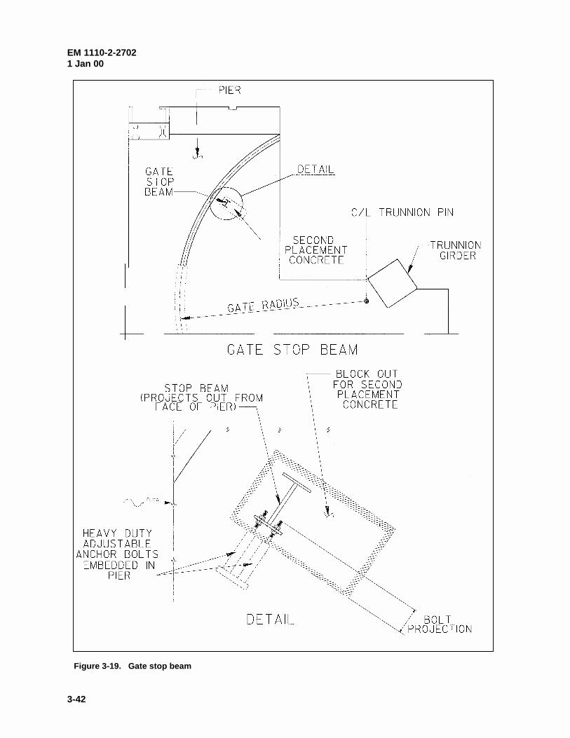
EM 1110-2-27021 Jan 00
3-42
Figure 3-19. Gate stop beam

EM 1110-2-27021 Jan 00
3-43
Figure 3-20. Typical gate bumper assembly