tacoma narrows bridge collapse - american association of physics
TRANSCRIPT
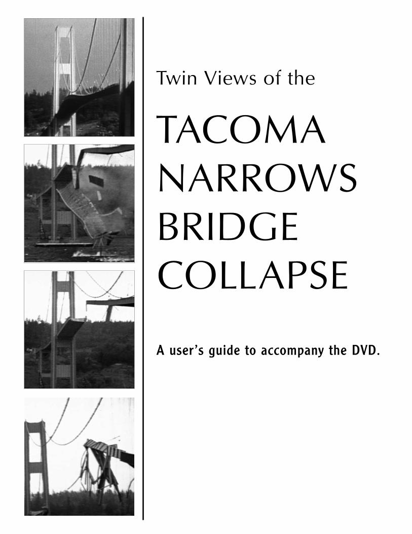
Twin Views of the
TACOMANARROWSBRIDGECOLLAPSE
A user’s guide to accompany the DVD.
Twin Views of the Tacoma Narrows Bridge Collapse
Copyright © 2000, American Association of Physics Teachers
This DVD and Teacher’s Guide were produced with the support of the AAPT Venture Fund at the University of Nebraska–Lincoln by Robert G. Fuller, Charles R. Lang, and Roberta H. Lang.
Published and Distributed by: American Association of Physics Teachers One Physics Ellipse College Park, MD 20740-3845
301-209-3333 www.aapt.org
ISBN 0-917853-95-4
Table of Contents
Tacoma Narrows Bridge History . . . . . . . . . . . . . . . . . . . . . . . . . . . . . . . . . . . . . . . . . . 2
Synopses of the Video Segments Tacoma Narrows Bridge Collapse . . . . . . . . . . . . . . . . . . . . . . . . . . . . . . . . . . . . 3 Franklin Miller, Jr . (1963) The Puzzle of the Tacoma Narrows Bridge Collapse . . . . . . . . . . . . . . . . . . . . . 4 R .G . Fuller, D .A . Zollman, & T .C . Campbell (1979)
Tacoma Narrows Bridge Collapse . . . . . . . . . . . . . . . . . . . . . . . . . . . . . . . . . . . . . . . . 5 Franklin Miller, Jr .
The Physics of the Tacoma Narrows Bridge Collapse . . . . . . . . . . . . . . . . . . . . . . . . 8 Robert G . Fuller and Dean A . Zollman
Personal Interest Items About the First Bridge . . . . . . . . . . . . . . . . . . . . . . . . . . . . . 13 compiled by Robert G . FullerSuggested Educational Activities Elementary Students (Grades K—6) . . . . . . . . . . . . . . . . . . . . . . . . . . . . . . . . . 16 Physical Science Students (Grades 7—12) . . . . . . . . . . . . . . . . . . . . . . . . . . . . 19 Physics Students (Grades 10—16) . . . . . . . . . . . . . . . . . . . . . . . . . . . . . . . . . . 23 Additional Literature About Bridges . . . . . . . . . . . . . . . . . . . . . . . . . . . . . . . . 22
Bibliography . . . . . . . . . . . . . . . . . . . . . . . . . . . . . . . . . . . . . . . . . . . . . . . . . . . . . . . . . . 25
� Tacoma Narrows Bridge History
The first Tacoma Narrows Bridge was built between November 23, 1938, and July 1, 1940, at a cost of approximately $6,400,000 . Some physical properties of the bridge were:
Total length: 5000 feetSpan length: 2800 feetWidth (center-to-center): 39 feet, two
lanes of trafficHeight of side girders: 8 feet
This bridge exhibited large vertical oscillations even during the construction . Shortly after it was opened to traffic, the bridge was christened “Galloping Gertie” by the people of the Tacoma area .
Critical decisions, such as the length of the main span and the use of plate girders, were made upon the recommendation of L .S . Moisseiff, a consulting engineer from New York . By the time of the bridge’s collapse, F .B . Farquharson, of the Department of Civil Engineering at the University of Washington, had been retained as a consulting engineer and was attempting to stop the bridge’s oscillations . Farquharson took some of the pictures that appeared in the original films .
Barney Elliott, proprietor of The Camera Shop in Tacoma, and his co-workers shot the color
film of the construction and collapse of the first Tacoma Narrows Bridge . Elliott won a prize for the outstanding newsreel film of 1940 for his Tacoma Narrows film . He turned the film over to the film library of the University of Washington, Seattle .
Both the Miller segment and the Fuller, Zollman, & Campbell segment were made by editing the film from the University of Washington, Seattle library, which contains pictures taken by Barney Elliott and F .B . Farquharson .
The script for the narration that accompanies the Fuller, Zollman, & Campbell segment was adapted from the formal statements given by Farquharson and Ken Arkin, chairperson of the Washington Toll Bridge Authority, during the formal investigation of the bridge collapse . Leonard Coatsworth, a reporter for the Tacoma News Tribune, drove the last car onto the bridge and reported his experiences in the newspaper . His words begin and end the Fuller, Zollman, & Campbell segment .
After the various studies of the collapse, a new suspension bridge was constructed at the same location . The new bridge is four lanes wide and has open grid sides instead of solid I-beams . It was opened on October 14, 1950, and has not displayed any of the interesting oscillatory properties of the first bridge .
Tacoma Narrows Bridge History
Synopses of the Film Segments �
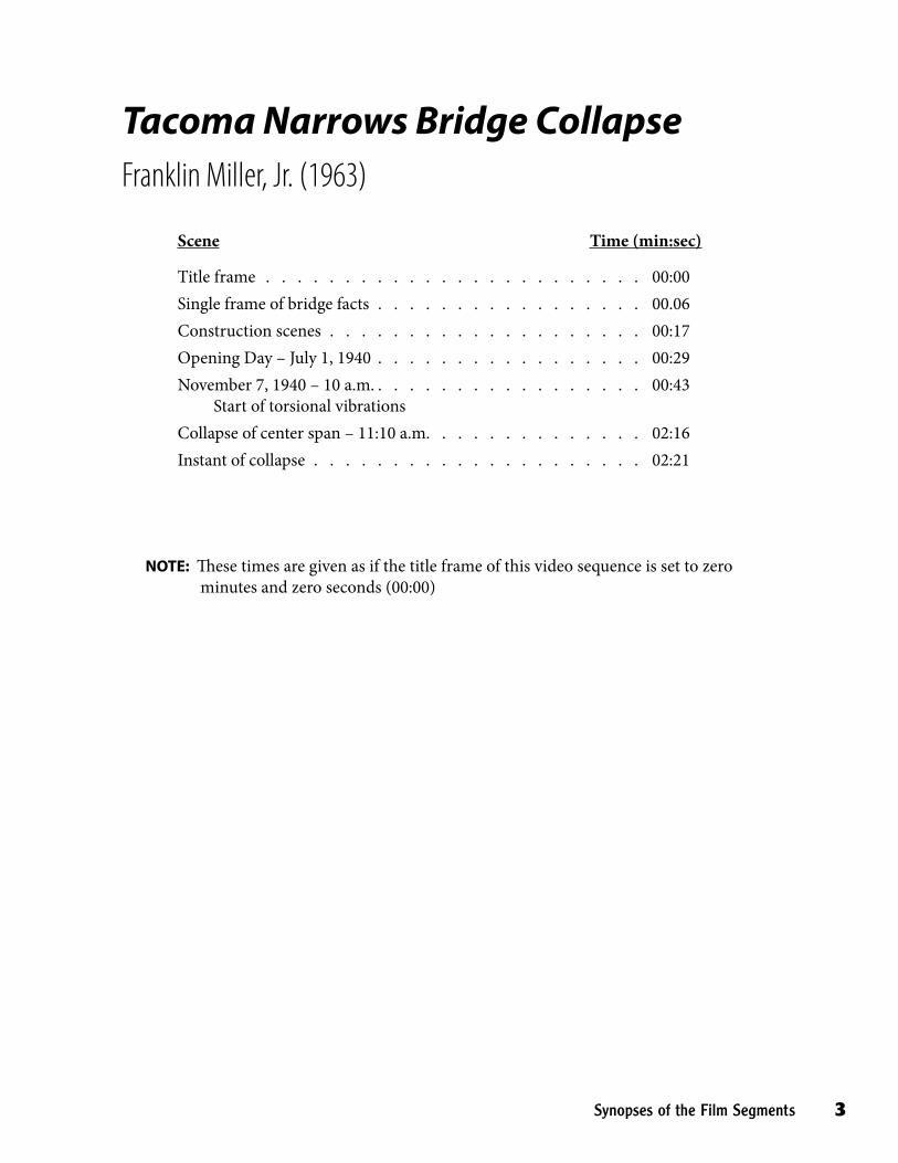
Tacoma Narrows Bridge CollapseFranklin Miller, Jr. (1963)
Scene Time (min:sec)
Title frame . . . . . . . . . . . . . . . . . . . . . . . . 00:00Single frame of bridge facts . . . . . . . . . . . . . . . . . 00 .06Construction scenes . . . . . . . . . . . . . . . . . . . . 00:17Opening Day – July 1, 1940 . . . . . . . . . . . . . . . . . 00:29November 7, 1940 – 10 a .m . . . . . . . . . . . . . . . . . . 00:43 Start of torsional vibrationsCollapse of center span – 11:10 a .m . . . . . . . . . . . . . . 02:16Instant of collapse . . . . . . . . . . . . . . . . . . . . . 02:21
NOTE: These times are given as if the title frame of this video sequence is set to zero minutes and zero seconds (00:00)
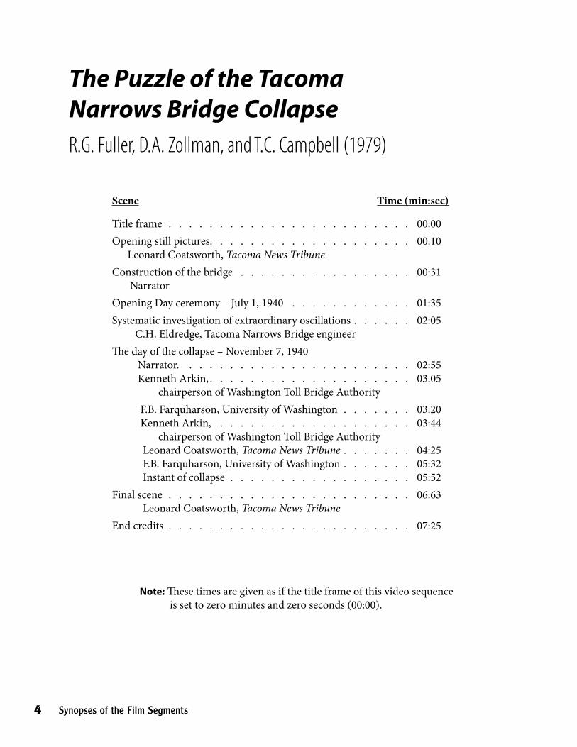
The Puzzle of the Tacoma Narrows Bridge CollapseR.G. Fuller, D.A. Zollman, and T.C. Campbell (1979)
Scene Time (min:sec)
Title frame . . . . . . . . . . . . . . . . . . . . . . . . 00:00Opening still pictures . . . . . . . . . . . . . . . . . . . . 00 .10 Leonard Coatsworth, Tacoma News TribuneConstruction of the bridge . . . . . . . . . . . . . . . . . 00:31 NarratorOpening Day ceremony – July 1, 1940 . . . . . . . . . . . . 01:35Systematic investigation of extraordinary oscillations . . . . . . 02:05 C .H . Eldredge, Tacoma Narrows Bridge engineerThe day of the collapse – November 7, 1940 Narrator . . . . . . . . . . . . . . . . . . . . . . . 02:55 Kenneth Arkin, . . . . . . . . . . . . . . . . . . . . 03 .05 chairperson of Washington Toll Bridge Authority F .B . Farquharson, University of Washington . . . . . . . 03:20 Kenneth Arkin, . . . . . . . . . . . . . . . . . . . 03:44 chairperson of Washington Toll Bridge Authority Leonard Coatsworth, Tacoma News Tribune . . . . . . . 04:25 F .B . Farquharson, University of Washington . . . . . . . 05:32 Instant of collapse . . . . . . . . . . . . . . . . . . 05:52Final scene . . . . . . . . . . . . . . . . . . . . . . . . 06:63 Leonard Coatsworth, Tacoma News TribuneEnd credits . . . . . . . . . . . . . . . . . . . . . . . . 07:25
� Synopses of the Film Segments
Note: These times are given as if the title frame of this video sequence is set to zero minutes and zero seconds (00:00) .

Tacoma Narrows Bridge CollapseFranklin Miller, Jr. (1963)
Tacoma Narrows Bridge Collapse �
The failure of the Tacoma Narrows Bridge in 1940 is described in several publications . The following account is drawn from the official
investigations of the failure in the Texas A &M Col-lege Engineering Experiment Station Bulletin (College Station, TX)1 and the University of Washington Engi-neering Experiment Station Bulletin (Seattle, WA)2; and from private communication with Burt Farquharson, director of the Engineering Experiment Station at the University of Washington . More recent analysis is found in a paper by K .Y . Billah and R .H . Scanlan, pub-lished in the American Journal of Physics.3
The length of the main span (between towers) was 2800 feet, and the width between cables, center-to-cen-ter, was 39 feet . Even during construction, the bridge sometimes developed up-and-down wave motions of extraordinary amplitude . Corrective measures were applied: hydraulic buffers at each end of the main span (which, however, became inoperative soon after instal-lation) and diagonal stays (“ties”) between the stiffen-ing girders and cables at mid-span . After opening to traffic, hold-downs were installed tying the girders in the side spans to massive concrete blocks on land . These reduced the waves in the side spans but not in the main span .Span length: 2800 feetWidth (center-to-center): 39 feetStart of construction: November 23, 1938Opened for traffic: July 1, 1940Failure of bridge: November 7, 1940
In the four months of active life of the bridge before
failure, only vertical vibrations were observed prior to November 7, 1940 . Many such transverse modes of vibration were observed . The main towers were nodes of course, and there were from 0 to 8 nodes between the two main towers . The maximum double ampli-tude (crest to trough) was about 5 feet in a mode with 2 nodes between the towers; the frequency of vibra-tion at that time was 12 vibrations/minute . When the bridge was vibrating in this mode some motorists were uneasy at seeing a car ahead disappear from view, only to reappear again later during the crossing . The bridge was colloquially known as “Galloping Gertie .” Never-theless, motorists were spared a tedious ferry cross-ing, and revenue from the bridge traffic exceeded the anticipated amount .
The most frequently observed vertical vibration was one with no nodes between the towers (frequency of 8 vibrations/minute); this might well be called the fundamental mode . The maximum recorded double amplitude for this mode was 2 feet .
Measurements made before failure indicated a cor-relation between wind velocity and mode of vibration; higher velocities favored modes with higher frequency . Similar results were obtained in the years 1940-45 by mathematical analysis, as well as from scale-model tests . On the other hand, both observation and theory agree that there was no significant correlation between wind velocity and amplitude of vibration . Motions of several feet were sometimes observed with wind velocities as low as 3 or 4 miles/hour; at other times the bridge remained motionless in winds as high as 35 miles/hour .
1 . The Failure of the Tacoma Narrows Bridge: A Reprint of Original Reports . Texas A&M College Engineering Experiment Station Bulletin (College Sta-tion, TX) 78 (1944) .
2 . Aerodynamic Stability of Suspension Bridges. Univ . of Washington Engineering Experiment Station Bulletin (Seattle, WA)116, parts I—IV (1949 –54) .3 . K .Y . Billah and R .H . Scanlan, “Resonance, Tacoma Narrows bridge failure, and undergraduate physics textbooks,” Amer. J. Phys. 59 (1991), pp .
118–124 .
The K-bracing under the deck was probably weakened during a midnight storm several days prior to November 7, 1940 . During the storm the bridge was observed by only one person, who reported its behavior to be different from any previous behavior . This is interpreted to mean that the bridge had a larger amplitude of vertical vibration than had previously been observed .
Early on the morning of November 7, the bridge developed motions of a type previously observed, but with larger-than-usual amplitude . The wind velocity was 40 to 45 miles/hour, larger than any previously encountered by the bridge . Traffic was shut down . By 9:30 a .m . the span was vibrating in eight or nine segments with a frequency of 36 vibrations/minute and a double amplitude of about 3 feet . While measurements were under way, at about 10 a .m . the main span abruptly began to vibrate torsionally in two segments with a frequency of 14 vibrations/minute . Later the torsional frequency changed to 12 vibrations/minute . The amplitude of torsional vibration quickly built up to about 35° each direction from the horizontal . The change to torsional mode “appeared to take place without any intermediate stages and with such extreme violence that the span appeared about to roll completely over . The most startling condition arose out of the fact that, from a line of sight very nearly parallel to the bridge the upper side of the roadway was visible while what appeared to be a nearly perpendicular view of the bottom of the roadway was offered on the Tacoma side .” The main span broke up shortly after 11 a .m .
During most of the catastrophic torsional vibra-tion there was a transverse nodal line at mid-span, and a longitudinal nodal line down the center of the roadway (the yellow center stripe) . Note that Farqu-harson sensibly strides (?) down the nodal line as he leaves the bridge after making observations on the condition of the stays and, incidentally, trying to save a small dog in a stalled car . (The dog was frightened, refused to leave the car, and perished along with the bridge .) Other torsional modes appeared briefly from time to time during the hour before the bridge gave way under the stresses which so greatly exceeded the design values .
The crucial event shortly after 10 a .m . which di-rectly led to the catastrophic torsional vibration, was apparently the loosening of the north cable in its col-lar which was tied to the deck girder by diagonal stays . If these ties are very secure they tend to inhibit the 1-node torsion mode . If they are weak and loose, this mode, if externally excited, can proceed more easily to large amplitudes . For the Tacoma Narrows Bridge, the diagonal ties did inhibit this mode at first but they be-came loosened (one broke, one cable clamp slipped) . The mode was then driven by auto-excitation forces of which the steady wind was the energy source . At 9:30 a .m ., photos made at the center of the bridge showed that the diagonal stays A and B were alternately slack and therefore partially ineffective . It is probable that the (unsuspected) failure of the K-bracing several days earlier had thrown an added stress on these stays . The center of the cable was moving back and forth relative to the center of the suspended span . However, at that time there was no slipping of the collar C itself rela-tive to the cable . Evidently, at about 10 a .m ., this collar started to slip back and forth, with a double amplitude of about 42 inches . This allowed the structure to twist as one of the main cables became longer on one side of the center and shorter on the other side . The wind velocity was large enough to cause this mode of tor-sion to build up, until collapse inevitably took place .
Following failure of the center span, the cables, originally parabolic, assumed a free-hanging catenary shape . Release of tension allowed the two towers to sag shoreward some 25 feet (measured at the top) . The cables remained intact except for a 42-inch section in the center of north cable over which the collar had scraped; 500 of the 6308 strands of No . 6 galvanized cold-drawn steel wire were ruptured by the sliding collar .
The Tacoma Narrows Bridge was unusually long and narrow compared with other suspension bridges previously built . The original design called for stiffen-ing the suspended structure with trusses . However, funds were not available, and a cheaper stiffening was adopted using 8-foot tall girders running the length of the bridge on each side . These girders are shown in the film sequence during construction of the bridge . Unfortunately, the stiffening was inadequate . The
� Tacoma Narrows Bridge Collapse
theory of aerodynamic stability of suspension bridges had not yet been worked out, and wind-tunnel facilities were not readily available due to the prewar military effort . (Incidentally, a tunnel moving great quantities of air at rather slow velocities, carefully controlled, would have been needed .) As a result, a scale model was constructed (standard practice) and applied to the evaluation of the bridge under static conditions (including wind forces) . However, the desirability of a three-dimensional dynamic model was recognized, and such a model (first of its kind) was under development and in partial use at the time of collapse . The problem of stability involves aerody-namic lift and is sensitive to the profile of the deck . Plans were under way to burn a series of large holes through the plate girders, but the gale got there first . Later wind-tunnel tests with a model of the original bridge showed that this emergency measure would have helped enhance stability .
The bridge was rebuilt using the original anchor-ages and tower foundations . The main cable spacing was increased to 60 feet (four lanes of traffic) and the towers increased in height by 59 feet to 507 feet . Studies at the University of Washington Engineer-ing Experiment Station using a dynamic 1:50 model, coupled with extensive mathematical analysis, resulted in a design for the new bridge that used deep stiffening trusses instead of the 8-feet girders of the original bridge . The new bridge was opened to traffic in the winter of 1950-51, and during that winter it was exposed to some of the highest winds of recent years . The bridge is entirely successful .
TheoryAs described in the 1991 paper by Billah and Scan-
lan,4 the motion of the bridge was an example of “an aerodynamically induced condition of self-excitation or negative damping in a torsional degree of freedom .” It was not a case of resonance, although that term is
indeed erroneously used in one of the captions in the film first edited in 1962 . True, there are some features similar to resonance: a large periodic motion at one of the natural frequencies of oscillation of the struc-ture, maintained by a relatively small continuously applied source of energy . But true resonance requires the periodic application of a small driving force in synchronism with a natural frequency of the struc-ture . The wind had no such frequency; it was a steady, rather strong wind of about 42 miles/hour . Analysis dating back to the 1940s and 1950s shows that when a steady wind strikes a non-streamlined surface such as the side of the bridge deck, a “flutter wake” is pro-duced which feeds energy back into the system . The energy tended to increase the motion of the structure . On the other hand, in all modes of transverse vibra-tion, as the amplitude of vibration increased, so also did the damping factor, and the vibration was self-limited . Not so for the torsional modes: there was one particular torsional mode of vibration for which, at large amplitudes, the damping became negative . This one mode of torsional vibration was exceptional; the positive feedback from the flutter wakes caused the system’s amplitude to increase steadily until structural failure occurred .
An analogy may be helpful here: when the bow is drawn steadily across a violin string, energy is fed into the string from the muscles of the player . But the frequency of the vibration is controlled by the string’s mass, length, and tension, not by any applied resonant frequency of the bow .
The original 16-mm footage of the bridge collapse was recorded by Barney Elliott, owner of The Camera Shop, who by an accident of history was document-ing the non-destructive transverse vibrations for a study being made by the engineers at the University of Washington Engineering Experiment Station . The Ta-coma Narrows Bridge Collapse footage was transcribed from a film originally compiled and edited at the Ohio State University .5
4 . Billah and Scanlan, 118-124 .
5 . Franklin J . Miller, Tacoma Narrows Bridge Collapse (Columbus, OH: Ohio State University, 1963), film . Supported by a grant from the National Science Foundation . All rights reserved . Not licensed for television use .
Tacoma Narrows Bridge Collapse �
The Physics of the Tacoma Narrows Bridge CollapseRobert G. Fuller and Dean A. Zollman
IntroductionNo film of physics phenomena is more interesting
to students than the single concept film of the collapse of the Tacoma Narrows Bridge . We have lost track of the number of copies that have been worn out or destroyed in our film loop projectors . Because of the great amount of student interest in the Tacoma Nar-rows Bridge collapse, we selected that film as the basis for our first videodisc, The Puzzle of the Tacoma Nar-rows Bridge Collapse .1 During the development of the materials for the videodisc, we learned much about its collapse and about bridge resonances in general . In this paper we review the available information and translate from the language of engineers to that of physicists .
BackgroundThe Tacoma Narrows Bridge was not the first suspension bridge to collapse. In fact, a survey of the history of suspension bridges shows that several were destroyed by wind or other oscillating forces. (See Table 1.)
However, the Tacoma Narrows Bridge was by far the longest and most expensive suspension bridge to collapse due to interaction with the wind . Per-haps because nearly 50 years had elapsed since the previous collapse of a bridge, this collapse seemed so striking . Or perhaps Barney Elliott’s memorable motion pictures of the torsional vibration mode of this bridge made it famous . For whatever reason, it is an event never to be forgotten in the annals of bridge
1 . Robert G . Fuller, Dean A . Zollman, and Thomas C . Campbell, The Puzzle of the Tacoma Narrows Bridge Collapse (New York: John Wiley and Sons, Inc ., 1979), videodisc .
Bridge Designer Span length (feet) Failure date
Dryburgh (Scotland) J. and W. Smith 260 1818
Union (England) Sir Samuel Brown 449 1821
Nassau (Germany) L. and W. 245 1834
Brighton (England) Sir Samuel Brown 255 1836
Montrose (Scotland) Sir Samuel Brown 432 1838
Menai (Wales) T. Telford 580 1839
Roche (France) LeBlanc 641 1852
Wheeling (US) C. Ellet 1010 1854
Niagara (US) E. Serrell 1041 1864
Niagara (US) S. Keefer 1260 1889
Tacoma Narrows L. Moisseiff 2800 1940
Table 1. Collapsed Suspension Bridges
� The Physics of the Tacoma Narrows Bridge Collapse
construction . The work of Sir Samuel Brown should not be overlooked . One will notice that he had a rash of bridge collapses in the 19th century . In addition, it has been reported that one of his bridges actually collapsed when a battalion of soldiers marched across it, lending support to the warning given each semester by physics teachers to their students .
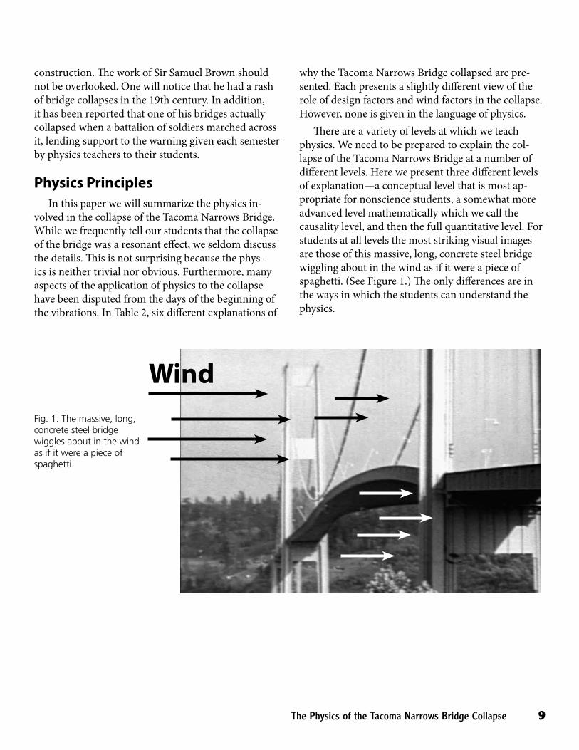
Physics PrinciplesIn this paper we will summarize the physics in-
volved in the collapse of the Tacoma Narrows Bridge . While we frequently tell our students that the collapse of the bridge was a resonant effect, we seldom discuss the details . This is not surprising because the phys-ics is neither trivial nor obvious . Furthermore, many aspects of the application of physics to the collapse have been disputed from the days of the beginning of the vibrations . In Table 2, six different explanations of
why the Tacoma Narrows Bridge collapsed are pre-sented . Each presents a slightly different view of the role of design factors and wind factors in the collapse . However, none is given in the language of physics .
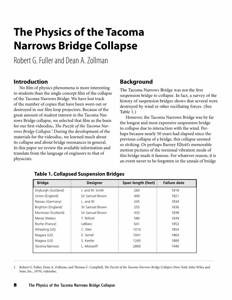
There are a variety of levels at which we teach physics . We need to be prepared to explain the col-lapse of the Tacoma Narrows Bridge at a number of different levels . Here we present three different levels of explanation—a conceptual level that is most ap-propriate for nonscience students, a somewhat more advanced level mathematically which we call the causality level, and then the full quantitative level . For students at all levels the most striking visual images are those of this massive, long, concrete steel bridge wiggling about in the wind as if it were a piece of spaghetti . (See Figure 1 .) The only differences are in the ways in which the students can understand the physics .
Fig. 1. The massive, long, concrete steel bridge wiggles about in the wind as if it were a piece of spaghetti.
Wind
The Physics of the Tacoma Narrows Bridge Collapse �
Table 2: Why Did the Tacoma Narrows Bridge Collapse?
1. “It is very improbable that resonance with alternating vortices plays an important role in the oscillations of suspension bridges . First, it was found that there is no sharp correlation between wind velocity and oscillation frequency such as is required in case of resonance with vortices whose frequency depends on the wind velocity . Secondly, there is no evidence for the formation of alternating vortices at a cross section similar to that used in the Tacoma Bridge, at least as long as the structure is not oscillating . It seems that it is more correct to say that the vortex formation and frequency is determined by the oscillation of the structure than that the oscillatory motion is induced by the vortex formation .” Source: Ammann, O .H ., T . Von Karman, and G .B . Woodruff . “The Failure of the Tacoma Narrows Bridge .” Report to
the Federal Works Agency . Washington, DC (March 28, 1941) .
2. “The primary cause of the collapse lies in the general proportions of the bridge and the type of stiffening girders and floor . The ratio of the width of the bridge to the length of the main span was so much smaller and the vertical stiffness was so much less than those of previously constructed bridges that forces heretofore not considered became dominant .” Source: Paine, C ., et al . “The Failure of the Suspension Bridge Over Tacoma Narrows .” Report to the Narrows Bridge
Loss Committee (June 26, 1941) .
3. “Once any small undulation of the bridge is started, the resultant effect of a wind tends to cause a building up of vertical undulations . There is a tendency for the undulations to change to a twisting motion, until the torsional oscillations reach destructive proportions .” Source: Steinman, David B ., and Sara Ruth Watson . Bridges and Their Builders. New York: Putnam’s Sons, 1941 .
4 . “The experimental results described in a (1942) report indicated rather definitely that the motions were a result of vortex shedding .” Source: Aerodynamic Stability of Suspension Bridges. Univ . of Washington Engineering Experiment Station Bulletin
(Seattle, WA) 1 .16 (1952) .
5. “Summing up the whole bizarre accident, Galloping Gertie tore itself to pieces, because of two characteristics: 1) It was a long, narrow, shallow, and therefore very flexible structure standing in a wind ridden valley; 2) Its stiffening support was a solid girder, which, combined with a solid floor, produced a cross section peculiarly vulnerable to aerodynamic effects .” Source: Gies, Joseph. Bridges and Men. Garden City, NY: Doubleday, 1963 .
6. “Aerodynamic instability was responsible for the failure of the Tacoma Narrows Bridge in 1940 . The magnitude of the oscillations depends on the structure shape, natural frequency, and damping . The oscillations are caused by the periodic shedding of vortices on the leeward side of the structure, a vortex being shed first from the upper section and then the lower section .”
Source: Houghton, E .L ., and N .B . Carruthers . Wind Forces on Buildings and Structures: An Introduction . New York: John Wiley and Sons, Inc ., 1976 .
10 The Physics of the Tacoma Narrows Bridge Collapse

Conceptual LevelStudents who are not able to follow a mathemati-
cal analysis of the bridge and its interaction with the wind are best served by a conceptual approach to the application of physics to the collapse of the bridge . We believe at this level the most satisfying explanation for the students is the idea of sympathetic vibrations . Every system has a natural fundamental vibration frequency . If forces are exerted on that system at the right frequency and phase, then sympathetic vibra-tions can be excited . Oscillating forces at the right frequency and phase can cause sympathetic vibrations of catastrophic proportions . The forces applied to the bridge by the wind were applied at a natural frequency of the bridge . Thus, the amplitude of the bridge’s oscil-lations increased until the steel and concrete could no longer stand the stress . (As one shall see before long, a correct wording of the statements emphasizes the oscillations of the forces applied by the wind and not the oscillations of the wind itself .)
Causality LevelThe next level of presentation, which we call the
causality level, is directed to students who hear the conceptual level explanation and ask the question: But how does the fluctuating force of just the right fre-quency arise on the bridge by the wind blowing across it? The first idea that comes to mind is that the gusty
wind had pulses striking the bridge at just the appro-priate frequency to cause the large oscillations . Closer examination of this explanation shows it cannot be right . While all winds have fluctuations in their wind speeds, these tend to be random in phase and variable in frequency . The gusts of wind are not an appropri-ate explanation . Furthermore, the kinds of forces that need to be exerted on the bridge are up-and-down forces transverse to the direction of the wind . The wind was blowing across the bridge from one side to the other, and the forces on the bridge were acting up and down . An explanation for these oscillating verti-cal forces lies in a concept called vortex shedding . When a wind that exceeds a minimum speed blows around any object, vortices will be formed on the back side of that object . (See Figure 2 .)
As the wind increases in speed, the vortices form on alternate sides of the down-wind side of the ob-ject, break loose, and flow downstream . At the time a vortex breaks loose from the backside of the object, a transverse force is exerted on the object . The frequen-cy of these fluctuating eddies is about 20 percent of the ratio of the velocity of the wind to the width of the object . These lateral forces can be as much as twice as large as the drag forces . Then, vortex shedding allows us to understand the exerting of fluctuating vertical forces on the Tacoma Narrows Bridge even though the wind was blowing across it in a transverse, hori-zontal direction .
Fig. 2. When a wind that exceeds a minimum speed blows around any object, vortices will be formed on the back side of that object.
The Physics of the Tacoma Narrows Bridge Collapse 11
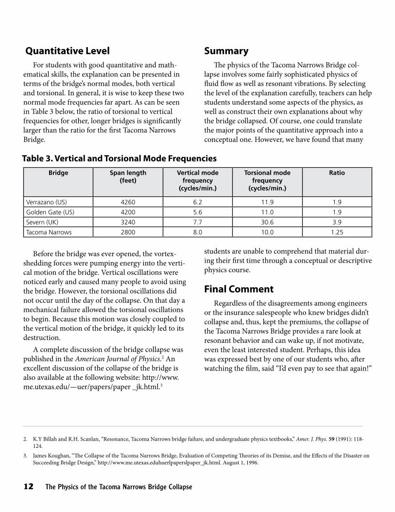
Quantitative LevelFor students with good quantitative and math-
ematical skills, the explanation can be presented in terms of the bridge’s normal modes, both vertical and torsional . In general, it is wise to keep these two normal mode frequencies far apart . As can be seen in Table 3 below, the ratio of torsional to vertical frequencies for other, longer bridges is significantly larger than the ratio for the first Tacoma Narrows Bridge .
Before the bridge was ever opened, the vortex- shedding forces were pumping energy into the verti-cal motion of the bridge . Vertical oscillations were noticed early and caused many people to avoid using the bridge . However, the torsional oscillations did not occur until the day of the collapse . On that day a mechanical failure allowed the torsional oscillations to begin . Because this motion was closely coupled to the vertical motion of the bridge, it quickly led to its destruction .
A complete discussion of the bridge collapse was published in the American Journal of Physics .2 An excellent discussion of the collapse of the bridge is also available at the following website: http://www .me .utexas .edu/—uer/papers/paper _jk .html .3
SummaryThe physics of the Tacoma Narrows Bridge col-
lapse involves some fairly sophisticated physics of fluid flow as well as resonant vibrations . By selecting the level of the explanation carefully, teachers can help students understand some aspects of the physics, as well as construct their own explanations about why the bridge collapsed . Of course, one could translate the major points of the quantitative approach into a conceptual one . However, we have found that many
students are unable to comprehend that material dur-ing their first time through a conceptual or descriptive physics course .
Final CommentRegardless of the disagreements among engineers
or the insurance salespeople who knew bridges didn’t collapse and, thus, kept the premiums, the collapse of the Tacoma Narrows Bridge provides a rare look at resonant behavior and can wake up, if not motivate, even the least interested student . Perhaps, this idea was expressed best by one of our students who, after watching the film, said “I’d even pay to see that again!”
Bridge Span length(feet)
Vertical mode frequency
(cycles/min.)
Torsional modefrequency
(cycles/min.)
Ratio
Verrazano (US) 4260 6.2 11.9 1.9
Golden Gate (US) 4200 5.6 11.0 1.9
Severn (UK) 3240 7.7 30.6 3.9
Tacoma Narrows 2800 8.0 10.0 1.25
Table 3. Vertical and Torsional Mode Frequencies
2 . K .Y Billah and R .H . Scanlan, “Resonance, Tacoma Narrows bridge failure, and undergraduate physics textbooks,” Amer. J. Phys. 59 (1991): 118-124 .
3 . James Koughan, “The Collapse of the Tacoma Narrows Bridge, Evaluation of Competing Theories of its Demise, and the Effects of the Disaster on Succeeding Bridge Design,” http://www .me .utexas .eduhuerlpaperslpaper_jk .html . August 1, 1996 .
1� The Physics of the Tacoma Narrows Bridge Collapse
Personal Interest Items About the First BridgeCompiled by Robert G. Fuller
With a disaster of the magnitude of the collapse of the Tacoma Narrows Bridge, many stories of general interest can be
described to show the human, as well as the physics, interest . For example, a headline in the Tacoma News Tribune in July 1940, states, “Bouncing Span Will Soon Be Quieted Down .”
It continues, “What makes a bridge bounce has been asked many times in the past few weeks as the Narrows span has approached completion . Engineers declare the principal reason the span has bounced in the immediate past was because it was out of bal-ance due to the concrete deck and walks being put in in sections . Now that the concrete work is com-pleted and the span still has a tendency to buck under certain conditions it is because the wind, swinging the middle span to one side draws the towers toward the center, lifting the approach sections . Then the deck swings back dropping the outside sections and sending a vibration across the center section . Repeat this and you have a motion which might give you what Mark Twain called Pardon ex moi, or at least the jitters . To take this tendency out of the span the engineers spent $10,000 for four hydraulic jacks which are to act as shock absorbers . If they don’t take out all of the vibration what is known as storm cables will be rigged and these are certain to stop the buck-ing . In any case there is nothing dangerous about it and if you are riding across the span you are not likely to notice the vibrations . Only foot passengers, or
motorists who stop, get the effect . Some of the swing-ing is due to the narrowness of the span, it being the narrowest span for its length on record . It would be possible with a 100-miles/hour wind for the span to swing sideways 20 feet but who ever saw a 100-miles/hour wind in these parts?” l
Another interesting item was the Tacoma News Tribune editorial on August 25, 1940, which dis-cussed the tolls which were being charged for cross-ing the Tacoma Narrows Bridge . “There is no truth in the rumor that part of the Narrows Bridge toll is for the scenic railway effects . The charge is for crossing only and the bounce is free .”2 (This was one of the first public comments about the bounce after the bridge was opened .)
A third article explains how the cables that were to be attached to the bridge would curb its bounc-ing . “There is nothing unusual about the antics of the Narrows span, Eldredge states, although those of this bridge are aggravated by its slender proportions necessitated by shortage of funds with which to build it . The Narrows span is narrower in proportion to its length than any bridge in the world and at the same time the girders, which would be expected to stiffen it are shallower than those of any similar structure . The Whitestone bridge, recently completed in New York, has as much bounce as the Narrows bridge, ac-cording to reports, but instead of publicizing it New Yorkers have done everything they could to keep it quiet . There is nothing dangerous about the perfor-
1 . “Bouncing Span Will Soon Be Quieted Down,” Tacoma News Tribune, 2 July 1940, Tacoma Narrows Bridge Edition, 9-B .
2 . “Those Bridge Tolls,” Tacoma News Tribune and Sunday Ledger, 25 August 1940, 10-A .
Personal Interest Items About the First Bridge 1�
mance which in no way affects the strength or safety of the Narrows span, Mr . Eldredge states . Aside from affording a basis for tall tales of the span’s cavorting the bridge’s bouncing is having no real effect whatever . Motion in the span deck is caused by the center span being swung out of line by a puff of air . This draws the tops of the towers together, lifting the two outside spans . As the center span swings back the shore end spans drop, starting the wave motion which is further aggravated by swinging of the center span . As the center span is designed to raise and lower 10 feet or more, due to changes in temperature, the four foot hop of the bounce does not put any strain on it which the design does not take care of with a large factor of safety . Work on the bridge is still being done under the toll bridge authority’s contract with the Pacific Bridge company, Mr . Eldredge states . Steel work will be handled by the Bethlehem Steel company, T Mar-tinson representing the company and concrete and other work by Woodworth & Cornell .”3
On November 9, 1940, the Tacoma News Tribune reported, “A local bank had its billboard by the bridge which said ‘as secure as the Narrows Bridge’ removed within hours of the collapse .”4
Insurance companies also had their share of prob-lems with the bridge . Shortly after the collapse the Tacoma News Tribune reported:
“BRIDGE INSURANCE WAS $5,200,000Tacoma Narrows bridge was insured for $5,200,000—approximately 80 per cent of its value it was revealed in insurance circles Friday .”5
Over the next several months the Tacoma business community was surprised by the trial and conviction
of a prominent Seattle insurance man who had col-lected the premium and overlooked mailing it to his insurance company:
December 3, 1940—Hallett R . French, a promi-nent Seattle insurance man, a general agent for Merchants Fire Assurance Co ., was jailed on $2000 bond for grand larceny . He wrote an $800,000 policy on the bridge but did not notify the national office and kept the $8000 premium .February 8, 1941—French was sentenced to a 15-year prison term by Judge Douglas . December 1942 —French, who had been pa-roled by Governor Langlie to work in a war industry, was working as a ship fitter .
The collapse of the Tacoma Narrows Bridge was a watershed in the design of suspension bridges . That was recognized as early as December 1940 by Walter A . Averill in the magazine, Pacific Builder and Engi-neer, and it seems appropriate to have a quote from him at this time:“Of inestimable importance to the field of bridge design is the collapse of the Tacoma Narrows Bridge, third longest suspension bridge in the world . Blame for the failure is commonly placed upon cumulative undulation and twisting induced by aerodynamic forces .“Aerodynamic forces never have been taken into consideration in the design of any bridge . Heretofore bridges have been designed to withstand static stresses only . From now on, bridge designers must consider dynamic actions and aerodynamic effects . Wind tun-nels, elastic models, dynamic models, and studies of aerodynamics, resonance and damping must now take
3 . “Cables Will Curb Bridge’s Bouncing,” Tacoma News Tribune, 6 September 1940 .
4 . “Signboard Slogan Loses Value When Big Bridge Falls,” Tacoma News Tribune, 9 November, 1940 .
5 . “25 Share in Bridge Loss; Insurance Farmed Out Among Many Companies,” Tacoma News Tribune, 9 November, 1940 .
6 . Walter A . Averill, Pacific Builder and Engineer . December 1940 .
1� Personal Interest Items About the First Bridge
their place in the design of any highly elastic bridge .”6
And finally, as you might expect, the collapse of such a large structure was not without controversy among the community of civil engineers . The follow-ing quote is from an article by David Steinman that appeared in the American Scientist:“Shortly after the Tacoma Bridge was opened and its undulatory behavior was reported in technical periodicals, I communicated with the engineers of the Tacoma span, offering to make my discoveries available . They replied that they knew all about
them and that they did not need my help . Three months later the Tacoma span was wrecked by its oscillations . The amazing feature of the catastrophe was the confidence of the bridge authorities in the safety of the structure and their failure to apply adequate corrective measures before opening the bridge to traffic . On the morning of the failure, after the oscillations had become alarming, the engineer in charge finally decided that diagonal stays were desirable; he rushed to the telephone to order the wire ropes for early installation but when he returned to the bridge, the span was gone . ” 7
7 . David B . Steinman, “Suspension Bridges: The Aerodynamic Problem and Its Solution,” American Scientist 42 (1954): 397-438 .
Personal Interest Items About the First Bridge 1�

Elementary Students (Grades K-6)Watch the Fuller, Zollman, & Campbell segment with your students . This second segment is less physics-in-tensive and contains more general background infor-mation about the construction of the bridge . Please be aware that both segments mention the death of a dog . However, there is no visual representation of the dog; the dog is only mentioned in the audio narration .Note: You may want to play back portions of the film as your students answer the questions . Time cod-ing is provided throughout this activities section; the time coding indicates the portion of the DVD that correlates to each exercise . The time of each event is given in time code from the beginning of this video sequence starting at zero minutes and zero seconds (00:00) .
IntroductionA. Listen to the audio at the beginning of the second
segment (01:14) . Question: What materials were used to construct
the bridge? Answer: Concrete and steel/iron .B. Have students look at the size of the girder . Have
students lift a sample of steel/iron . Question: Is the bridge heavy? Answer: Yes, very heavy because the bridge has a
lot more steel than I am holding .
Lower Grades: “Tacoma Bridge Is Falling Down”View the bridge in its up-and-down motion (01:52) and then in its twisting motion (03:20) . Play “Tacoma
Bridge is Falling Down” to the tune of “London Bridge is Falling Down .”A. Before playing the game: Question: How would you wave your arms to be
like the bridge before it starts to fall? Answer: (In words or by showing .) My arms should
go up and down together . (The students stand with their arms in front of them and wave them up and down together .)
Question: How would you wave your arms to be like the bridge when it is about to fall?
Answer: (In words or by showing .) My arms would be out like an airplane and I would tilt from side to side . (Their arms extend out from the shoulders . The students tilt so that one arm goes up as the other goes down .)
B. Playing the game: Students stand in a line with enough room in front
of them and to the side so that they do not strike anything . Sing the song with the corresponding motions:
Tacoma Bridge is falling down, falling down, falling down; (wave arms in front)
Tacoma Bridge is falling down; (tilt from side to side)
All fall down! (fall to the ground)C . After the game: Point out to the students that, like the old London
Bridge, the old Tacoma Narrows Bridge was re-placed by a new one that does not wiggle or twist or fall down .
Suggested Educational Activities
1� Suggested Educational Activities for Elementary Students
Upper Grades: Setting Up a Ratio Question: If the girder is 8 feet tall, then how high
upward does the outside edge of the bridge swing above the point where the bridge was level? Pause the DVD when the bridge is at its highest point (03:35) . Have the students use a ruler or measuring tape to measure the height of the girder and the distance of the bridge above its normal position . Then, set up a ratio and proportion problem .
Answer: For different size monitors the actual measurements will be different . However, the proportions will be the same . (We found the ratio to be about 1 to 1 .7, or a swing of about 13 .6 feet!)
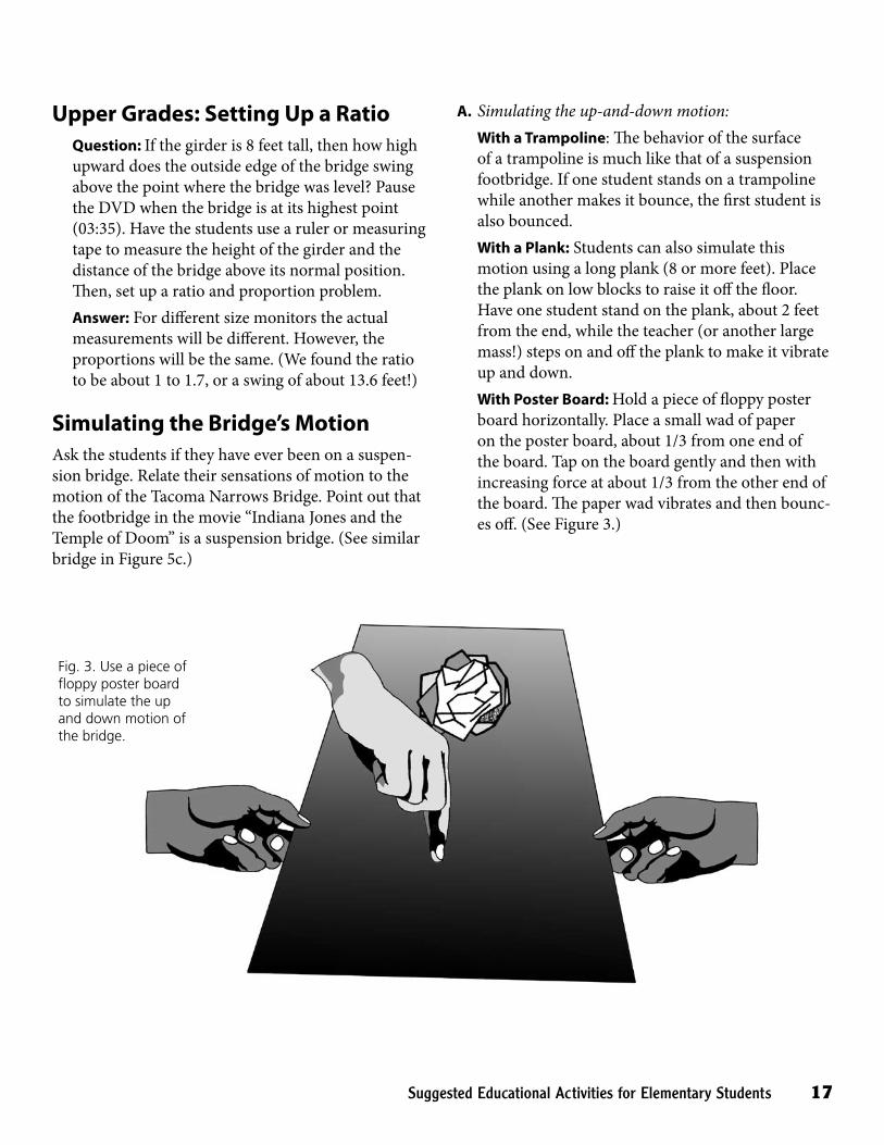
Simulating the Bridge’s MotionAsk the students if they have ever been on a suspen-sion bridge . Relate their sensations of motion to the motion of the Tacoma Narrows Bridge . Point out that the footbridge in the movie “Indiana Jones and the Temple of Doom” is a suspension bridge . (See similar bridge in Figure 5c .)
A. Simulating the up-and-down motion: With a Trampoline: The behavior of the surface
of a trampoline is much like that of a suspension footbridge . If one student stands on a trampoline while another makes it bounce, the first student is also bounced .
With a Plank: Students can also simulate this motion using a long plank (8 or more feet) . Place the plank on low blocks to raise it off the floor . Have one student stand on the plank, about 2 feet from the end, while the teacher (or another large mass!) steps on and off the plank to make it vibrate up and down .
With Poster Board: Hold a piece of floppy poster board horizontally . Place a small wad of paper on the poster board, about 1/3 from one end of the board . Tap on the board gently and then with increasing force at about 1/3 from the other end of the board . The paper wad vibrates and then bounc-es off . (See Figure 3 .)
Suggested Educational Activities for Elementary Students 1�
Fig. 3. Use a piece of floppy poster board to simulate the up and down motion of the bridge.
Question: What makes the “bridge” (Indiana Jones’ footbridge, trampoline, plank, poster board) move up and down?
Answer: The people walking or bouncing the “bridge .”
Question: What made the Tacoma Narrows Bridge move up and down?
Answer: The first answer that may come up is that cars made it bounce up and down . Point out to the students that there were no cars moving on the bridge at the time of collapse . (The one car on the bridge was stopped .) There has to be something pushing on the bridge . The DVD suggests it is the wind blowing through the narrow gorge .
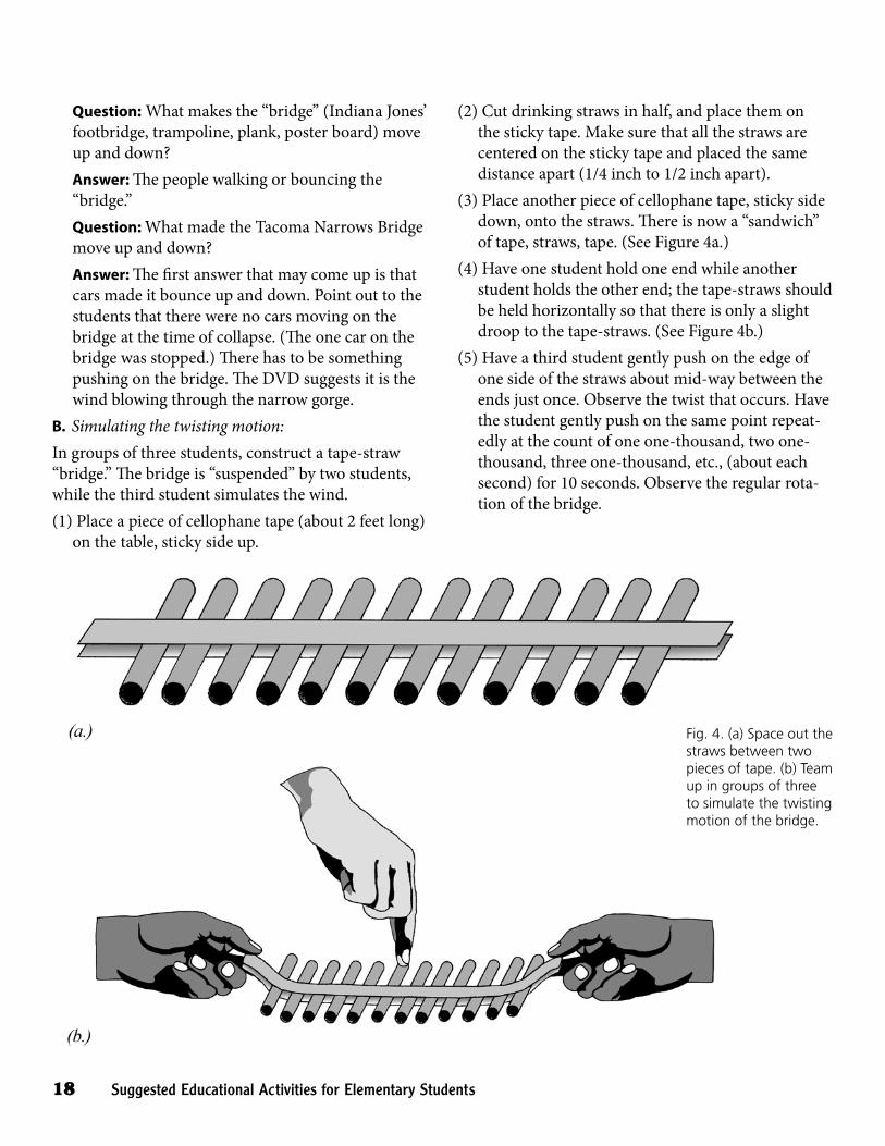
B. Simulating the twisting motion:In groups of three students, construct a tape-straw “bridge .” The bridge is “suspended” by two students, while the third student simulates the wind .(1) Place a piece of cellophane tape (about 2 feet long)
on the table, sticky side up .
(2) Cut drinking straws in half, and place them on the sticky tape . Make sure that all the straws are centered on the sticky tape and placed the same distance apart (1/4 inch to 1/2 inch apart) .
(3) Place another piece of cellophane tape, sticky side down, onto the straws . There is now a “sandwich” of tape, straws, tape . (See Figure 4a .)
(4) Have one student hold one end while another student holds the other end; the tape-straws should be held horizontally so that there is only a slight droop to the tape-straws . (See Figure 4b .)
(5) Have a third student gently push on the edge of one side of the straws about mid-way between the ends just once . Observe the twist that occurs . Have the student gently push on the same point repeat-edly at the count of one one-thousand, two one-thousand, three one-thousand, etc ., (about each second) for 10 seconds . Observe the regular rota-tion of the bridge .
Fig. 4. (a) Space out the straws between two pieces of tape. (b) Team up in groups of three to simulate the twisting motion of the bridge.
1� Suggested Educational Activities for Elementary Students
Question: What made the tape-straw “bridge” twist from side to side?
Answer: _______(student’s name) pushed on it . Question: What made the tape-straw “bridge” keep
on twisting? Answer: _______(student’s name) kept pushing
again and again . Question: What could have made the Tacoma Nar-
rows Bridge twist from side to side? Answer: The wind pushed on it .
Sound and the Tacoma Narrows BridgeWhen you study sound, you could show this video as an example of an object that vibrates . Question: How did the bridge vibrate?Answer: The bridge vibrated up and down (transverse motion) and in a twisting motion (torsional motion) .
Suggested Educational Activities for Physical Science Students 1�
Watch the Fuller, Zollman, & Campbell segment with your students . This second segment is less physics-in-tensive and contains more general background infor-mation about the construction of the bridge .Note: You may want to play back portions of the DVD as your students answer the questions . Time cod-ing is provided throughout this activities section; the time coding indicates the portion of the DVD that correlates to each exercise . The time of each event is given in time code from the beginning of this video sequence starting at zero minutes and zero seconds (00:00) .
IntroductionListen to the audio at the beginning of the second segment (01:14) . Question: What materials were used to construct
the bridge? Indicate whether each material is an element, a compound, or a mixture .
Answer: Concrete and steel . Concrete is a mixture of cement, sand, and gravel . Steel is a mixture called an alloy . Most of the steel is iron .
Preliminary Calculations Question: If the girder is 8 feet tall, then how high
upward does the outside edge of the bridge swing above the point where the bridge was level? Pause the video when the bridge is at its highest point (03:21) . Have the students use a ruler or measur-ing tape to measure the height of the girder and the distance of the bridge above its normal position . Then, set up a ratio and proportion problem .
Answer: For different size monitors the actual mea-surements will be different . However, the propor-tions will be the same . (We found the ratio to be about 1 to 1 .7, or a swing of about 13 .6 feet!)
Question: Estimate the time for the girder to swing from bottom to top .
Answer: Use a stopwatch and measure the total time for several complete up-and-down motions of the edge of the bridge . Divide the total time for several swings by the total number of complete swings . (We found a time of about 2 .5 seconds .)
Question: Calculate the average speed of the girder as it goes up and down .
Answer: The girder oscillates up and down a total distance of about 27 feet in 2 .5 seconds for an aver-age speed of about 11 feet/second .
Physical Science Students (Grades 7-12)
�0 Suggested Educational Activities for Physical Science Students
(a) (b)
(c) (d)
(e) (f)
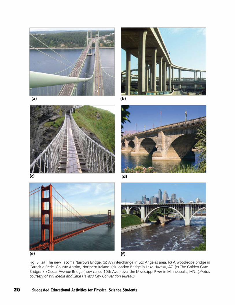
Fig. 5. (a) The new Tacoma Narrows Bridge. (b) An interchange in Los Angeles area. (c) A wood/rope bridge in Carrick-a-Rede, County Antrim, Northern Ireland. (d) London Bridge in Lake Havasu, AZ. (e) The Golden Gate Bridge. (f) Cedar Avenue Bridge (now called 10th Ave.) over the Mississippi River in Minneapolis, MN. (photos courtesy of Wikipedia and Lake Havasu City Convention Bureau)
Suspension vs. Truss Bridges Question: What is the difference between a bridge
such as the Tacoma Narrows Bridge, the Golden Gate Bridge, or a rope footbridge, and a bridge such as the London Bridge, a bridge across the Mississippi River, or an overpass on the interstate? (See Figure 5 .)
Answer: The first three bridges are suspension bridges . The last three are truss bridges .
Question: Why would suspension bridges be used instead of truss bridges?
Answer: Suspension bridges are preferable in a number of situations: (1) When the land sides are high enough for water traffic to pass under the bridge without opening the bridge; (2) when it would be difficult to build truss supports; (3) when it would hinder water traffic to have truss supports as close together as needed; and (4) when it would hinder both bridge and water traffic to have a sec-tion of the bridge swing out to let water traffic pass .
Forces Acting on the Bridge Question: What were some of the forces acting on
the central span of the Tacoma Narrows Bridge before it collapsed?
Answer: There is the force acting on the cables (tension), the weight of the bridge span and cables, and the force the wind exerts when it blows .
Question: What are the forces just after the bridge breaks?
Answer: The tension in the cable is gone except for the weight of the cables themselves . The wind still pushes on the cables and causes the falling pieces of bridge to swirl about . The bridge span falls because of the force due to gravity .
Question: Why does the car slide from the right side of the bridge to the left?
Answer: The twisting motion of the bridge pushes the car up, and the force due to gravity pulls it down . The friction between the tires and the bridge surface is not great enough to hold the car in place, so it slides sideways .
Kinetic and Potential Energy Question: As the bridge rocks back and forth,
during the swinging motion, when is the kinetic energy of the bridge the greatest?
Answer: The kinetic energy is greatest when the bridge swings through its normal (equilibrium) position .
Question: When is the potential energy of the bridge the greatest?
Answer: The potential energy is greatest when the bridge reaches its greatest height of twist .
Question: Where did the energy to cause the bridge to twist come from?
Answer: It came from the wind pushing on it . Question: What evidence is there for how hard the
wind was blowing? Answer: The wind was blowing very hard judging
by the way the bushes were moving around .
Simulating the Bridge’s MotionIn groups of three students, construct a tape-straw “bridge .” The bridge is “suspended” by two students, while the third student simulates the wind .(1) Place a piece of cellophane tape (about 2-feet long)
on the table, sticky side up .(2) Cut drinking straws in half, and place them on
the sticky tape . Make sure that all the straws are centered on the sticky tape and placed the same distance apart (1/4 inch to 1/2 inch apart) .
(3) Place another piece of cellophane tape, sticky side down, onto the straws . There is now a “sandwich” of tape, straws, tape . (See Figure 4a .)
(4) Have one student hold one end while another student holds the other end; the tape-straws should be held horizontally so that there is only a slight droop to the tape-straws . (See Figure 4b .)
(5) Have a third student gently push on the edge of one side of the straws about midway between the ends just once . Observe the twist that occurs . Have the student gently push on the same point repeat-edly at the count of one one-thousand, two one-
Suggested Educational Activities for Physical Science Students �1
thousand, three one-thousand, etc ., (about each second) for 10 seconds . Observe the regular rota-tion of the “bridge .”
Question: What motion does the “bridge” have? Answer: It twists . Question: What is observed about the motion of
the “bridge”?
Answer: The “bridge” twists more and more each time it is pushed .
Question: Where does the kinetic energy of the twisting “bridge” come from?
Answer: The energy comes from the work done on it by the student .
Students are to first view the Miller segment with the audio off . After all questions have been answered, run the segment again, this time with the audio on . Time coding is provided throughout this activities section; the time coding indicates the portion of the DVD that correlates to each exercise . Time coding is given in the following format: (minutes : seconds) .
Key Information About the BridgeView the blue frame with the bridge information (00:06) . Copy down the length of the central span, the width of the roadway (cable-to-cable), and the height of the girders . (You will need this information for making later calculations .)
Span length = 2800 ftWidth (cable-to-cable) = 39 ftHeight of side girders = 8 ft
Estimating Using Scaling Question: View the man standing on the girder .
(Pause the DVD at the frame to the right .) Using the height of the girder, estimate:
(a) the height of the man (b) the distance between cable mounts Answer: Use the scaling between the actual mea-
sured heights on the monitor and the known height of the girder .
(a) the height of the man ~ 6 ft (b) the distance between cable mounts ~ 8 ft
IntroductionA. View the ceremonial crossing of the bridge (00 .30) . Question: What is happening here? Answer: This is the opening day celebration of the
bridge .B. View the blue frame that mentions a time of 10
a .m . (00 .43) . Question: What is meant by torsional mode? Answer: A wave that twists or partially rotates
about a central, linear axis .
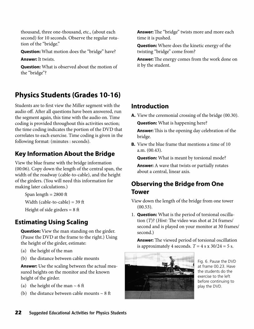
Observing the Bridge from One TowerView down the length of the bridge from one tower
(00 .53) .1 . Question: What is the period of torsional oscilla-
tion (T)? (Hint: The video was shot at 24 frames/second and is played on your monitor at 30 frames/second .)
Answer: The viewed period of torsional oscillation is approximately 4 seconds . T = 4 s x 30/24 = 5 s .
Physics Students (Grades 10-16)
�� Suggested Educational Activities for Physics Students
Fig. 6. Pause the DVD at frame 00.23. Have the students do the exercise to the left before continuing to play the DVD.
2 . Question: What is the frequency (f) of the torsional oscillation?
Answer: f = 1/T = 1/5 s = 0 .20 vib/s3 . Question: What is the wavelength of the torsional
wave along the bridge? Answer: There is one complete wavelength along
the bridge, so the wavelength is equal to 2800 feet .4 . Question: What is the velocity of the torsional
wave along the bridge? Answer: velocity = frequency x wavelength = 0 .20
cycle/s x 2800 ft/cycle = 560 ft/s5 . Question: What is the greatest angular amplitude
of the light poles measured from the horizontal? Estimate your value by viewing the film, marking on the screen with a dry-mark pen, and measuring with a protractor . Express your answer in degrees .
Answer: An angular amplitude of about 35° mea-sured from the horizontal should be observed .
6 . Question: Calculate the approximate greatest vertical displacement of the light poles .
Answer: sine q = vert . displ / 19 .5 ft vert . displ . = 19 .5 ft x sin 35° ~ 11 .2 ft7 . Question: What is the average linear velocity of the
light poles? Answer: vavg = Dd/Dt = 22 .4 ft/2 .5 s = 9 .0 ft/s8 . Question: What is the average angular velocity of
the light pole? Answer: w = v/r = 9 .0 ft/s / 19 .5 ft = 0 .46 rad/s9 . Question: What is the maximum angular velocity
of the light pole? Answer: w(max) = 2 x w(avg) = 0 .92 rad/s10 . Question: What is the minimum angular velocity? Answer: w(min) = 0 rad/s11 . Question: What is the angular acceleration of the
light pole? Answer: a = Dw /Dt = (0 .92 – 0) rad/s / 1 .25 s =
0 .74 rad /s2
12 . Question: Why does the walking person try to stay near the center of the roadway?
Answer: The center of the roadway is a longitudinal nodal line . This is a place of smallest disturbance and of easiest walking .
Observing the Bridge from the BankView the sideways view of the bridge as seen from a camera position to the right of the bridge located on the bank (01:26) .1 . Question: Compare your earlier vertical displace-
ment measurement of the twisting bridge with a di-rect measurement, using the girder height of 8 feet to scale this out . How do your two determinations of the vertical displacement of the bridge compare?
Answer: The vertical displacement from the horizontal is approximately 8 to 10 feet .
2 . Question: Compare the mode of vibration to the left of the left tower with the rotational mode of vibration of the center span .
Answer: The mode of vibration of the bridge left of the center span is a transverse vibration rather than a torsional vibration .
Observing the Collapse of the BridgeView the collapse of the bridge’s central span (02:21) .1 . Question: Use the known acceleration of gravity
to estimate the height of the central span above the water surface (ignoring air resistance) .
Answer: Time of fall to the water is about 4 s as seen on the monitor . Actual time is 4 s x 30/24 = 5 s .
d = 1/2 a t 2 = (1/2)(10 m/s2)(25 s2) = 125 ft2 . Question: Compare your calculated distance with a
direct measurement using the height of the girder as 8 feet .
Suggested Educational Activities for Physics Students ��
The following is a listing of juvenile titles about bridg-es . This listing is not an endorsement of the titles . This list was compiled from elementary teacher submis-sions and from books in print listings .
Canizares, Susan, and Daniel Moreton . Bridges . Scholastic, Inc ., 1998 . ISBN 0439045819 .
Canzler, Lillian C . Bridges . Clark Canzler Books, 1986 . Grades K-3 . ISBN 0941769003 .
Cooper, Jason . Bridges. Rourke Enterprises, Inc ., 1991 . Grades K-4 . ISBN 086592628X .
Dunn, Andrew . Bridges (Structures). Thomson Learn-ing, 1993 . Grades 5-8 . ISBN 1568470282 .
Hill, Lee S . Bridges Connect . The Lerner Publishing Group, 1996 . ISBN 1575050218 .
Hunter, Ryan Ann . Cross a Bridge. Holiday House, Inc ., 1998 . Illustrated by Edward Miller . Grades K-1 . ISBN 0823413403 .
Kaner, Etta . Bridges. General Distribution Services, Inc ., 1997 . Illustrated by Pat Cupples . Grades 3-7 . ISBN 1550741462 .
Johmann, Carol A ., and Elizabeth J . Rieth . Bridges: Amazing Structures to Design, Build & Test . Williamson Publishing, 1999 . Illustrated by Michael P . Kline . Grades 4-6 . ISBN 1885593309 .
Oxlade, Chris . Bridges. Raintree Steck-Vaughn Pub-lishers, 1997 . ISBN 0817243313 .
Ricciuti, Edward R . America’s Top 10 Bridges . Black-birch Press, Inc ., 1997 . Grades 3 and up . ISBN 1567111971 .
Richardson, Joy . Bridges. Franklin Watts, Inc ., 1994 . Grades 2-4 . ISBN 0531142892 .
Spangenburg, Ray, and Diane K . Moser . The Story of America’s Bridges. Replica Books, 1999 . Grades 6-9 . ISBN 0735102031 .
Willard, Keith, and Adele Richardson . Bridges (De-signing the Future) . The Creative Company, 1999 . ISBN 0886827183 .
Out-of-Print BooksArdley, Neil . Bridges . Garrett Educational Corpora-
tion, 1990 . Grades 4-7 . ISBN 0944483747 .Bridges & Tunnels, Modern Publishing, 1997 .
Grades K-2 . ISBN 1561449113 .Chester, Michael . Joseph Strauss, Builder of the Golden
Gate Bridge. Putnam’s Sons . Grades 4-8 . ISBN 0399603298 .
Corbett, Scott . Bridges. Four Winds Press . Grades 4-8 . ISBN 0590074644 .
Gaff, Jackie . Buildings, Bridges, and Tunnels. Random House Books for Young Readers, 1991 . Illustrated by Michael Fisher . Grades 2-5 . ISBN 0679808655 .
Kingston, Jeremy . How Bridges Are Made . Facts on File, Inc . Grades 7 and up . ISBN 0816000409 .
Robbins, Ken . Bridges. Dial Books for Young Readers, 1991 . ISBN 0803709307 .
Wilson, Forrest . Bridges Go from Here to There. John Wiley and Sons, Inc ., 1993 . Grades 1 and up . ISBN 0471143693 .
Additional Literature About Bridges
�� Additional Literature About Bridges
Bibliography
Articles“Aerodynamic Stability of Suspension Bridges .” Univ.
of Washington Engineering Experiment Station Bul-letin (Seattle, WA) 116, parts I-IV (1949-54) .
Billah, K .Y ., and R .H . Scanlan . “Resonance, Tacoma Narrows bridge failure, and under-graduate physics textbooks” Amer. J. Phys. 59 (1991): 118-124 .
“The Failure of the Tacoma Narrows Bridge: A Reprint of Original Reports .” Texas A&M College Engineer-ing Experiment Station Bulletin (College Station, TX) 78 (1944) .
Steinman, David B . “Suspension Bridges: The Aerody-namic Problem and Its Solution .” American Scien-tist 42 (1954): 397-438 .
“Wind Effects on Bridges and Other Flexible Struc-tures .” Notes on Applied Science (National Physical Laboratory, London) 11 (1955) .
BooksAndrew, Charles E . Final Report on the Tacoma
Narrows Bridge. Olympia, WA: Washington Toll Bridge Authority, 1952 . (This is a report on the new bridge .)
Gies, Joseph . Bridges and Men. Garden City, NY: Doubleday, 1963 .
Gould, Phillip L ., and S .H . Abu-Sitta . Dynamic Re-sponse of Structures to Wind and Earthquake Load-ing . New York: John Wiley and Sons, Inc ., 1980 .
Houghton, E .L ., and N .B . Carruthers . Wind Forces on Buildings and Structures: An Introduction. New York: John Wiley and Sons, Inc ., 1976 .
O’Connor, Colin . Design of Building Superstructures. New York: John Wiley and Sons, Inc ., 1971 .
Sachs, Peter . Wind Forces in Engineering. 2d ed . Ox-ford: Pergamon Press, 1978 .
Simiu, Emil, and Robert H . Scanlan . Wind Effects on Structures: An Introduction to Wind Engineering . New York: John Wiley and Sons, Inc ., 1978 .
Steinman, David B ., and Sara Ruth Watson . Bridges and Their Builders. New York: Putnam’s Sons, 1941 .
Thompson, J .M .T . Instabilities and Catastrophes in Science and Engineering . New York: John Wiley and Sons, Inc ., 1982 .
WebsitesKoughan, James . “The Collapse of the Tacoma Nar-
rows Bridge, Evaluation of Competing Theories of its Demise, and the Effects of the Disaster on Succeeding Bridge Design .” http://www .me .utexas .edu/-uer/papers/paper jk .html . August 1, 1996 .
Bibliography ��