table saw - leeway workshop, llc, home of the … · table saw steel city tool works manual part...
TRANSCRIPT

User ManualRead and understand this manual before using machine.
TABLE SAW
STEEL CITY TOOL WORKS Manual Part No. OR70131
C US®
Model Numbers3560035605
Shown with optional Fence

2
THANK YOU for purchasing your new Steel City Table
Saw. This table saw has been designed, tested, and inspected
with you, the customer, in mind. When properly used and
maintained, your table saw will provide you with years of
trouble free service, which is why it is backed by one of the
longest machinery warranties in the business.
This table saw is just one of many products in the Steel
City’s family of woodworking machinery and is proof of
our commitment to total customer satisfaction.
At Steel City we continue to strive for excellence each and
every day and value the opinion of you, our customer. For
comments about your table saw or Steel City Tool Works,
please visit our web site at www.steelcitytoolworks.com .

3
TABLE OF CONTENTS
INTRODUCTION
This user manual is intended for use by anyone working with this machine. It should be kept availablefor immediate reference so that all operations can be performed with maximum efficiency and safety.Do not attempt to perform maintenance or operate this machine until you have read and understand theinformation contained in this manual.
The drawings, illustrations, photographs, and specifications in this user manual represent your machineat time of print. However, changes may be made to your machine or this manual at any time with noobligation to Steel City Tool Works.
INTRODUCTION
SECTION 1 Warranty .................................................................................................................................................4
SECTION 2 Product Specifications ............................................................................................................................7
SECTION 3 Accessories and Attachments ................................................................................................................7
SECTION 4 Definition of Terms..................................................................................................................................8
SECTION 5 Feature Identification ..............................................................................................................................9
SECTION 6 General Safety......................................................................................................................................10
SECTION 7 Product Safety ......................................................................................................................................12
SECTION 8 Electrical Requirements........................................................................................................................13
SECTION 9 Unpacking & Inventory..........................................................................................................................15
SECTION 10 Assembly ..............................................................................................................................................17
SECTION 11 Adjustments ..........................................................................................................................................22
SECTION 12 Operations ............................................................................................................................................28
SECTION 13 Maintenance .........................................................................................................................................33
SECTION 14 Troubleshooting ....................................................................................................................................34
SECTION 15 Parts List..........................................................................................................................................36-41

4
WARRANTY
STEEL CITY TOOL WORKS5 YEAR LIMITED WARRANTY
Steel City Tool Works, LLC (“SCTW”) warrants all “STEEL CITY TOOL WORKS” machinery to befree of defects in workmanship and materials for a period of 5 years from the date of the original retailpurchase by the original owner. SCTW will repair or replace, at its expense and at its option, anySCTW machine, machine part, or machine accessory which in normal use has proven to be defective,provided that the customer returns the product, shipping prepaid, to an authorized service center withproof of purchase and provides SCTW with a reasonable opportunity to verify the alleged defect byinspection. This warranty does not apply to defects due directly or indirectly to misuse, abuse,negligence, accidents, or lack of maintenance, or to repairs or alterations made or specifically authorizedby anyone other than SCTW. Normal wear components are also excluded under this coverage. Everyeffort has been made to ensure that all SCTW machinery meets the highest quality and durabilitystandards. We reserve the right to change specifications at any time due to our commitment tocontinuous improvement of the quality of our products.
EXCEPT AS SET FORTH ABOVE, SCTW MAKES NO EXPRESS OR IMPLIED REPRESENTA-TIONS OR WARRANTIES WITH RESPECT TO ITS MACHINERY, OR ITS CONDITION,MERCHANTABILITY, OR FITNESS FOR ANY PARTICULAR PURPOSE OR USE. SCTWFURNISHES THE ABOVE WARRANTIES IN LIEU OF ALL OTHER WARRANTIES, EXPRESSOR IMPLIED, INCLUDING THE WARRANTIES OF MERCHANTABILITY AND FITNESS FOR APARTICULAR PURPOSE, WHICH ARE HEREBY SPECIFICALLY DISCLAIMED.
SCTW SHALL NOT BE LIABLE FOR ANY (A) SPECIAL, INDIRECT, INCIDENTAL, PUNITIVEOR CONSEQUENTIAL DAMAGES, INCLUDING WITHOUT LIMITATION LOSS OF PROFITS,ARISING FROM OR RELATED TO THIS WARRANTY, THE BREACH OF ANY AGREEMENT ORWARRANTY, OR THE OPERATION OR USE OF ITS MACHINERY, INCLUDING WITHOUTLIMITATION DAMAGES ARISING FROM DAMAGE TO FIXTURES, TOOLS, EQUIPMENT,PARTS OR MATERIALS, DIRECT OR INDIRECT LOSS CAUSED BY ANY OTHER PARTY, LOSSOF REVENUE OR PROFITS, FINANCING OR INTEREST CHARGES, AND CLAIMS BY ANYTHIRD PERSON, WHETHER OR NOT NOTICE OF SUCH POSSIBLE DAMAGES HAS BEENGIVEN TO SCTW; (B) DAMAGES OF ANY KIND FOR ANY DELAY BY OR FAILURE OF SCTWTO PERFORM ITS OBLIGATIONS UNDER THIS AGREEMENT; OR (C) CLAIMS MADE ASUBJECT OF A LEGAL PROCEEDING AGAINST SCTW MORE THAN ONE (1) YEAR AFTERSUCH CAUSE OF ACTION FIRST AROSE.
The validity, construction and performance of this Warranty and any sale of machinery by SCTW shallbe governed by the laws of the Commonwealth of Pennsylvania, without regard to conflicts of laws pro-visions of any jurisdiction. Any action related in any way to any alleged or actual offer, acceptance orsale by SCTW, or any claim related to the performance of any agreement including without limitationthis Warranty, shall take place in the federal or state courts in Allegheny County, Pennsylvania.
STEEL CITY TOOL WORKS

5
WARRANTY CARDName ________________________________________________
Street _______________________________________________
Apt. No. ______________________________________________
City_________________________ State ______ Zip __________
Phone Number_________________________________________
E-Mail________________________________________________
Product Description:_____________________________________
Model No.: ___________________________________________
Serial No. _____________________________________________
The following information is given on a voluntary basisand is strictly confidential.
1. Where did you purchase your STEEL CITY machine?
Store: ____________________________________________
City:______________________________________________
2. How did you first learn of Steel City Tool Works?
___ Advertisement ___ Mail Order Catalog
___ Web Site ___ Friend
___ Local Store Other_______________________
3. Which of the following magazines do you subscribe to?
___ American Woodworker ___ American How-To
––– Cabinetmaker ___ Family Handyman
___ Fine Homebuilding ___ Fine Woodworking
___ Journal of Light Construction ___ Old House Journal
___ Popular Mechanics ___ Popular Science
___ Popular Woodworking ___ Today’s Homeowner
___ WOOD ___ Woodcraft
___ WOODEN Boat ___ Woodshop News
___ Woodsmith ___ Woodwork
___ Woodworker ___ Woodworker’s Journal
___ Workbench Other_________________
4. Which of the following woodworking / remodeling shows doyou watch?
___ Backyard America ___ The American Woodworker
___ Home Time ___ The New Yankee Workshop
___ This Old House ___ Woodwright’s Shop
Other__________________________________________
5. What is your annual household income?
___ $20,000 to $29,999 ___ $30,000 to $39,999
___ $40,000 to $49,999 ___ $50,000 to $59,999
___ $60,000 to $69,999 ___ 70,000 to $79,999
___ $80,000 to $89,999 ___ $90,000 +
6. What is your age group?
___ 20 to 29 years ___ 30 to 39 years
___ 40 to 49 years ___ 50 to 59 years
___ 60 to 69 years ___ 70 + years
7. How long have you been a woodworker?
___ 0 to 2 years ___ 2 to 8 years
___ 8 to 20 years ___ over 20 years
8. How would you rank your woodworking skills?
___ Simple ___ Intermediate
___ Advance ___ Master Craftsman
9. How many Steel City machines do you own? _____________
10. What stationary woodworking tools do you own? Check all that apply.
___ Air Compressor ___ Band Saw
___ Drill Press ___ Drum Sander
___ Dust Collection ___ Horizontal Boring Machine
___ Jointer ___ Lathe
___ Mortiser ___ Panel Saw
___ Planer ___ Power Feeder
___ Radial Arm Saw ___ Shaper
___ Spindle Sander ___ Table Saw
___ Vacuum Veneer Press ___ Wide Belt Sander
Other____________________________________________
11. Which benchtop tools do you own? Check all that apply.
___ Belt Sander ___ Belt / Disc Sander
___ Drill Press ___ Band Saw
___ Grinder ___ Mini Jointer
___ Mini Lathe ___ Scroll Saw
___ Spindle / Belt Sander Other______________________
12. Which portable / hand held power tools do you own? Check all that apply.
___ Belt Sander ___ Biscuit Jointer
___ Dust Collector ___ Circular Saw
___ Detail Sander ___ Drill / Driver
___ Miter Saw ___ Orbital Sander
___ Palm Sander ___ Portable Thickness Planer
___ Saber Saw ___ Reciprocating Saw
___ Router Other_______________________
13. What machines / accessories would you like to see added to theSTEEL CITY line?
____________________________________________________
____________________________________________________
14. What new accessories would you like to see added?
____________________________________________________
____________________________________________________
15. Do you think your purchase represents good value?
___Yes ___ No
16. Would you recommend STEEL CITY products to a friend?
___ Yes ___ No
17. Comments:
____________________________________________________
____________________________________________________
____________________________________________________
____________________________________________________
____________________________________________________
!C
UT
HE
RE

6
Steel City Tool WorksP.O. Box 10529
Murfreesboro, TN 37129
PLACESTAMPHERE
FOLD ON DOTTED LINE
FOLD ON DOTTED LINE

7
PRODUCT SPECIFICATIONS
Model Number 35600 Model Number 35605
Motor type Induction Induction
HP 1.75 3
Amps 15 / 7.5 13
Volts 115 / 230 230
Hertz 60 60
RPM 3450 3450
Blade Tilt Left Left
Blade Drive Poly-V Belt Poly-V Belt
Blade Diameter 10-in 10-in
Blade Arbor 5/8-in 5/8-in
Number of Teeth 40 40
Blade Speed 3450 3450
Max Depth of cut at 90° 3-3/8-in 3-3/8-in
Max Depth of cut at 45° 2-1/4-in 2-1/4-in
Table in front of blade 12-1/2-in 12-1/2-inat max depth of cut
Max Dado width 13/16-in 13/16-in
Max Dado blade diameter 8-in 8-in
Left and right table wing 12-in cast iron 12-in cast iron
Product DimensionsFootprint 20” x 22” 20” X 22”
Length 44” 44”
Width 32” 32”
Height 40” 40”
Net Weight 320lbs 334lbs
Shipping DimensionsLength 30-1/2-in 30-1/2-in
Width 29-1/2-in 29-1/2-in
Height 43-in 43-in
Gross Weight 370 lbs 385 lbs
ACCESSORIES AND ATTACHMENTS
There are a variety of accessories available for your Steel City Product. For more information onany accessories associated with this and other machines, please contact your nearest Steel Citydistributor, or visit our website at: www.steelcitytoolworks.com.

8
DEFINITION OF TERMS
Anti-Kickback Fingers – A safety device attached tothe blade guard and splitter assembly designed tominimize the chance of a workpiece being thrown backduring a cutting operation.
Arbor – The shaft on which the blade or accessorycutting-tool is mounted.
Bevel Cut – The operation of making any cut with theblade set on a degree other than 90 degrees.
Compound Cut – The operation of making both abevel and a miter cut at one time.
Crosscut – The operation of making a cut across thegrain or width of a workpiece.
Dado – A non-through cut that produces a squarenotch. A dado is typically from 1/8-in. to 13/16-in. wide.A dado requires a special set of blades, not includedwith this table saw.
Featherboard – An accessory device that can be madeor purchased to help guide or hold down a workpieceduring cutting operations.
Freehand – A very dangerous operation of making acut without using the fence or miter gauge in a cuttingoperation. FREEHAND CUTS MUST NEVER BEPERFORMED ON A TABLE SAW.
Gum, Pitch or Resin – A sticky, sap based residue thatcomes from wood products.
Heeling – The misalignment of the blade to the miterslots; when the blade is not parallel to the miter slots.
Kerf – The material removed by the blade in the work-piece during any cutting operation.
Kickback – When the workpiece is thrown back towardthe operator at a high rate of speed during a cuttingoperation.
Miter Cut – The operation of making a cut using themiter gauge at any angle other than zero degrees.
Push Stick – An accessory device that can be made orpurchased to help push the workpiece through theblade. A push stick is used to keep the operator’shands away from the blade when ripping a narrowworkpiece.
Rabbet – A square notch in the edge of the workpiece.
Rip Cut – The operation of making a cut with the grainof the workpiece.
Saw Blade Path – The area that is directly in line withthe blade, including area over, under, behind and infront of it.
Set of the Saw Blade – The distance that the tips ofthe saw blade are angled outwards from the thicknessof the blade. The set of the saw blade teeth allows forthe blade body to pass safely through all cuts.
Table/Work Area – The total surface of the top of thetable saw on which the workpiece rests while set-up orcutting operations are being performed.

9
FEATURE IDENTIFICATION
A) Miter Gauge
B) Blade Guard Assembly
C) Motor Cover
D) Bevel Scale
E) Raise/Lower Handwheel
F) Bevel Adjustment Handwheel
G) Fence Hooks
H) On/Off Switch
(shown with an optional fence)
C
BA
G
EFH
D

10
TO AVOID serious injury and damage to the machine,read and follow all Safety and Operating Instructionsbefore assembling and operating this machine.
This manual is not totally comprehensive. It does notand can not convey every possible safety and opera-tional problem which may arise while using thismachine. The manual will cover many of the basic andspecific safety procedures needed in an industrial envi-ronment.
All federal and state laws and any regulations havingjurisdiction covering the safety requirements for use ofthis machine take precedence over the statements inthis manual. Users of this machine must adhere to allsuch regulations.
Below is a list of symbols that are used to attract yourattention to possible dangerous conditions.
This is the safety alert symbol. It is used to alert you topotential personal injury hazards. Obey all safety mes-sages that follow this symbol to avoid possible injury ordeath.
Indicates an imminently hazardous situation which, ifnot avoided, WILL result in death or serious injury.
Indicates a potentially hazardous situation which, if notavoided, COULD result in death or serious injury.
Indicates a potentially hazardous situation, if not avoid-ed, MAY result in minor or moderate injury. It may alsobe used to alert against unsafe practices.
CAUTION used without the safety alert symbol indi-cates a potentially hazardous situation which, if notavoided, may result in property damage.
This symbol is used to alert the user to useful informa-tion about proper operation of the machine.
GENERAL SAFETY
DANGER
NOTICE
CAUTION
Exposure to the dust created by power sanding, saw-ing, grinding, drilling and other construction activitiesmay cause serious and permanent respiratory orother injury, including silicosis (a serious lung dis-ease), cancer, and death. Avoid breathing the dust,and avoid prolonged contact with dust. The dustmay contain chemicals known to the State ofCalifornia to cause cancer, birth defects or otherreproductive harm.
2. ALWAYS wear eye protection. Any machine canthrow debris into the eyes during operations,which could cause severe and permanent eyedamage. Everyday eyeglasses are NOT safetyglasses. ALWAYS wear Safety Goggles (thatcomply with ANSI standard Z87.1) when operat-ing power tools.
WARNING
WARNING
CAUTION
!
!
!
!
! WARNING!
Some examples of these chemicals are:
• Lead from lead-based paints.
• Crystalline silica from bricks, cement and othermasonry products.
• Arsenic and chromium from chemically-treatedlumber.
Always operate tool in well ventilated area and pro-vide for proper dust removal. Use a dust collectionsystem along with an air filtration system wheneverpossible. Always use properly fitting NIOSH/OSHAapproved respiratory protection appropriate for thedust exposure, and wash exposed areas with soapand water.
WARNING!
1. To avoid serious injury and damage to the machine,read the entire User Manual before assembly andoperation of this machine.

11
4. ALWAYS wear a NIOSH/OSHA approved dustmask to prevent inhaling dangerous dust or air-borne particles.
8. AVOID a dangerous working environment. DONOT use electrical tools in a damp environmentor expose them to rain or moisture.
9. CHILDPROOF THE WORKSHOP AREA byremoving switch keys, unplugging tools from theelectrical receptacles, and using padlocks.
3. ALWAYS wear hearing protection. Plain cotton isnot an acceptable protective device. Hearingequipment should comply with ANSI S3.19Standards.
WARNING!
WARNING!
WARNING!
WARNING!
11. DO NOT FORCE the machine to perform an opera-tion for which it was not designed. It will do a saferand higher quality job by only performing operationsfor which the machine was intended.
12. DO NOT stand on a machine. Serious injury couldresult if it tips over or you accidentally contact anymoving part.
13. DO NOT store anything above or near the machine.
14. DO NOT operate any machine or tool if under theinfluence of drugs, alcohol, or medication.
15. EACH AND EVERY time, check for damaged partsprior to using any machine. Carefully check allguards to see that they operate properly, are notdamaged, and perform their intended functions.Check for alignment, binding or breakage of allmoving parts. Any guard or other part that is dam-aged should be immediately repaired or replaced.
16. Ground all machines. If any machine is suppliedwith a 3-prong plug, it must be plugged into a 3-contact electrical receptacle. The third prong isused to ground the tool and provide protectionagainst accidental electric shock. DO NOT removethe third prong.
17. Keep visitors and children away from any machine.DO NOT permit people to be in the immediate workarea, especially when the machine is operating.
18. KEEP protective guards in place and in workingorder.
19. MAINTAIN your balance. DO NOT extend yourselfover the tool. Wear oil resistant rubber soled shoes.Keep floor clear of debris, grease, and wax.
20. MAINTAIN all machines with care. ALWAYS KEEPmachine clean and in good working order. KEEP allblades and tool bits sharp.
21. NEVER leave a machine running, unattended. Turnthe power switch to the OFF position. DO NOTleave the machine until it has come to a completestop.
22. REMOVE ALL MAINTENANCE TOOLS from theimmediate area prior to turning the machine ON.
23. SECURE all work. When it is possible, use clampsor jigs to secure the workpiece. This is safer thanattempting to hold the workpiece with your hands.
24. STAY ALERT, watch what you are doing, and usecommon sense when operating any machine. DONOT operate any machine tool while tired or underthe influence of drugs, alcohol, or medication. Amoment of inattention while operating power toolsmay result in serious personal injury.
5. ALWAYS keep the work area clean, well lit, andorganized. DO NOT work in an area that has slip-pery floor surfaces from debris, grease, and wax.
6. ALWAYS unplug the machine from the electricalreceptacle when making adjustments, changingparts or performing any maintenance.
7. AVOID ACCIDENTAL STARTING. Make sure thatthe power switch is in the “OFF” position beforeplugging in the power cord to the electricalreceptacle.
10. DO NOT use electrical tools in the presence offlammable liquids or gasses.

12
PRODUCT SAFETY
1. Serious personal injury may occur if normal safetyprecautions are overlooked or ignored. Accidentsare frequently caused by lack of familiarity or failureto pay attention. Obtain advice from supervisor,instructor, or another qualified individual who isfamiliar with this machine and its operations.
2. Every work area is different. Always consider safe-ty first, as it applies to your work area. Use thismachine with respect and caution. Failure to do socould result in serious personal injury and damageto the machine.
4. TO REDUCE the risk of electrical shock. DONOT use this machine outdoors. DO NOTexpose to rain or moisture. Store indoors in adry area.
9. DO NOT handle the plug or table saw withwet hands.
25. USE ONLY recommended accessories. Use ofincorrect or improper accessories could cause seri-ous injury to the operator and cause damage to themachine. If in doubt, DO NOT use it.
26. THE USE of extension cords is not recommendedfor 230V equipment. It is better to arrange theplacement of your equipment and the installedwiring to eliminate the need for an extension cord.If an extension cord is necessary, refer to the chartin the Grounding Instructions section to determinethe minimum gauge for the extension cord. Theextension cord must also contain a ground wire andplug pin.
27. Wear proper clothing, DO NOT wear loose clothing,gloves, neckties, or jewelry. These items can getcaught in the machine during operations and pullthe operator into the moving parts. Users mustwear a protective cover on their hair, if the hair islong, to prevent it from contacting any moving parts.
28. SAVE these instructions and refer to them frequent-ly and use them to instruct other users.
29. Information regarding the safe and proper operationof this tool is also available from the followingsources:
Power Tool Institute1300 Summer AvenueCleveland, OH 44115-2851www.powertoolinstitute.org
National Safety Council1121 Spring Lake DriveItasca, IL 60143-3201
American National Standards Institute25 West 43rd Street, 4th floorNew York, NY 10036www.ansi.org
ANSI 01.1 Safety Requirements forWoodworking Machines, and the U.S. Departmentof Labor regulationswww.osha.gov
WARNING!
WARNING!
3. Prevent electrical shock. Follow all electrical andsafety codes, including the National Electrical Code(NEC) and the Occupational Safety and HealthRegulations (OSHA). All electrical connections andwiring should be made by qualified personnel only.
5. STOP using this machine, if at any time you experi-ence difficulties in performing any operation.Contact your supervisor, instructor or machine serv-ice center immediately.
6. Safety decals are on this machine to warn anddirect you to how to protect yourself or visitors frompersonal injury. These decals MUST be maintainedso that they are legible. REPLACE decals that arenot legible.
7. DO NOT leave the unit plugged into the electricaloutlet. Unplug the unit from the outlet when not inuse and before servicing, performing maintenancetasks, or cleaning.
8. ALWAYS turn the power switch “OFF” beforeunplugging the table saw.
10. USE accessories only recommended by Steel City.
11. DO NOT pull the table saw by the power cord.NEVER allow the power cord to come in contactwith sharp edges, hot surfaces, oil or grease.
12. DO NOT unplug the table saw by pulling on thepower cord. ALWAYS grasp the plug, not the cord.
13. REPLACE a damaged cord immediately. DO NOTuse a damaged cord or plug. If the table saw is notoperating properly, or has been damaged, left out-doors or has been in contact with water.
14. DO NOT use the table saw as a toy. DO NOT usenear or around children.

13
ELECTRICAL REQUIREMENTS
This manual is written for two specific models,Model No 35600 and Model No 35605. Please followthe specific requirements for your model saw.
MODEL NO 35600
The switch provided with your saw is a dual voltagecapable switch, meaning it is designed to function ateither 115 or 230 volts. The switch and saw comes
To reduce the risk of electric shock, follow all electri-cal and safety codes, including the National ElectricCode (NEC) and the Occupational Safety and HealthRegulations (OSHA). All electrical connections andwiring should be made by qualified personnel only.
15. ENSURE that the machine sits firmly on the floorbefore using. If the machine wobbles or is unstable,correct the problem by using shims or blocks priorto operation.
16. KEEP saw blade sharp and clean. Failure to do sogreatly increases friction, decreases cut quality, andincreases the possibility of a kickback.
17. MAKE CERTAIN the saw blade is parallel with themiter slots and with the rip fence. A blade that isnot aligned parallel can cause the workpiece to bepinched between the blade and the fence causingburning or kickbacks.
18. ALWAYS use blade guard on all through cuts. This will help prevent the cut from closing on theback of the saw blade. The blade guard also hasanti-kickback fingers which minimize the chanceof a workiece being thrown back during a cuttingoperation.
19. ALWAYS push the workpiece past the blade. DONOT release a workpiece until it is past the bladeand removed from the saw.
20. DO NOT execute a cut when you do not havecomplete control of the situation.
21. DO NOT cut a workpiece that is too large for you tohandle.
22. DO NOT use the rip fence as a guide when cross-cutting.
23. BE MINDFUL of flaws in the wood. Cutting awarped or twisted board along the rip fence can getpinched between the fence and the blade, causinga kickback.
24. ALWAYS remove cut off pieces and scraps fromthe table before starting the saw.
25. NEVER start the machine with the workpieceagainst the blade.
26. NEVER perform freehand operations. Use eitherthe fence or miter gauge to position and guide theworkpiece through the blade.
27. ALWAYS use a pushstick for ripping narrow work-pieces.
28. NEVER have any part of your body in line with thepath of the saw blade. If a kickback occurs withyou directly in front of the blade, a serious injurycan occur.
29. NEVER attempt to free a stalled blade without firstturning the machine off and disconnecting the sawfrom the power source.
WARNING! prewired for 115 volt operation. If you decide to convertthe saw to 230V, you will have to replace the 115 voltplug on the switch with a UL/CSA Listed plug, suitablefor 230 volts. The table saw with a 230 volt plug shouldonly be connected to an outlet having the same config-uration as the plug. No adapter is available or shouldbe used with the 230 volt plug. Once the modificationhas been made to the plug of the switch, be sure to fol-low the instructions under CHANGING MOTOR VOLT-AGE for changing the motor voltage from 115 volt to230 volt in the ADJUSTMENTS section of this manual.
MODEL NO 35605The switch provided with your saw is a magnetic switchdesigned for 230 volt single phase usage only. Theswitch has a plug that is designed to plug into a 230volt outlet. There are many different configurations for230 volt outlets, so it is conceivable that the configura-tion of the plug may not match the configuration of yourexisting outlet. If this is the case, you will have toreplace the plug with a UL/CSA approved plug thatmatches the configuration of your 230V outlet.

14
GROUNDING INSTRUCTIONS
This machine MUST BE GROUNDED while in use toprotect the operator from electric shock.
In the event of a malfunction or breakdown, GROUND-ING provides the path of least resistance for electriccurrent and reduces the risk of electric shock. The plugMUST be plugged into a matching electrical receptaclethat is properly installed and grounded in accordancewith ALL local codes and ordinances.
If a plug is provided with your machine DO NOT modifythe plug. If it will not fit your electrical receptacle, havea qualified electrician install the proper connections tomeet all electrical codes local and state. All connectionsmust also adhere to all of OSHA mandates.
IMPROPER ELECTRICAL CONNECTION of the equip-ment-grounding conductor can result in risk of electricshock. The conductor with the green insulation (with orwithout yellow stripes) is the equipment-grounding con-ductor. DO NOT connect the equipment-grounding con-ductor to a live terminal if repair or replacement of theelectric cord or plug is necessary.
Check with a qualified electrician or service personnel ifyou do not completely understand the groundinginstructions, or if you are not sure the tool is properlygrounded.
PLUGS/RECEPTACLES
• Electrocution or fire could result if this machine isnot grounded properly or if the electrical configura-tion does not comply with local and state electricalcodes.
• MAKE CERTAIN the machine is disconnectedfrom power source before starting any electricalwork.
• MAKE SURE the circuit breaker does not exceedthe rating of the plug and receptacle.
The motor supplied with your machine is either a115/230 dual voltage motor (Model 35600) or a dedicat-ed 230 volt, single phase motor (Model 35605). Neverconnect the green or ground wire to a live terminal.
The machine should only be connected to an outlethaving the same configuration as the plug.
EXTENSION CORDS
To reduce the risk of fire or electrical shock, use theproper gauge of extension cord. When using anextension cord, be sure to use one heavy enough tocarry the current your machine will draw.
The smaller the gauge-number, the larger the diameterof the extension cord is. If in doubt of the proper size ofan extension cord, use a shorter and thicker cord. Anundersized cord will cause a drop in line voltage result-ing in a loss of power and overheating.
USE ONLY a 3-wire extension cord that has a 3-pronggrounding plug and a 3-pole receptacle that accepts themachine’s plug.
If you are using an extension cord outdoors, be sure itis marked with the suffix “W-A” (“W” in Canada) to indi-cate that it is acceptable for outdoor use.
Make certain the extension cord is properly sized, andin good electrical condition. Always replace a worn ordamaged extension cord immediately or have itrepaired by a qualified person before using it.
Protect your extension cords from sharp objects, exces-sive heat, and damp or wet areas.
CAUTION
MINIMUM RECOMMENDED GAUGE FOR EXTENSION CORDS (AWG)
115 VOLT OPERATION ONLY
25’ LONG 50’ LONG 100’ LONG
0 to 6 Amps 18 AWG 16 AWG 16 AWG6 to 10 Amps 18 AWG 16 AWG 14 AWG
10 to 12 Amps 16 AWG 16 AWG 14 AWG12 to 15 Amps 14 AWG 12 AWG Not
recommended
MINIMUM RECOMMENDED GAUGE FOR EXTENSION CORDS (AWG)
230 VOLT OPERATION ONLY
25’ LONG 50’ LONG 100’ LONG
0 to 6 Amps 18 AWG 18 AWG 16 AWG6 to 10 Amps 18 AWG 18 AWG 14 AWG
10 to 12 Amps 16 AWG 16 AWG 14 AWG12 to 15 Amps 14 AWG 12 AWG Not
recommended
WARNING!
WARNING!
WARNING!
!

15
• The machine is heavy, two people are required tounpack and lift.
• Use a safety strap to avoid tip over when liftingmachine.
Check shipping carton and machine for damage beforeunpackaging. Carefully remove packaging materials,parts and machine from shipping carton. Always checkfor and remove protective shipping materials aroundmotors and moving parts. Lay out all parts on a cleanwork surface.
Remove any protective materials and coatings from allof the parts and the table saw. The protective coatings
UNPACKING & INVENTORY
A) Dust Port
B) Blade Guard and Splitter Assembly
C) On/Off Switch
D) Miter Gauge
A
H
G
B
C
D
F
E
I
WARNING!
WARNING!
can be removed by spraying WD-40 on them and wip-ing it off with a soft cloth. This may need redone sever-al times before all of the protective coatings areremoved completely.
After cleaning, apply a good quality paste wax to anyunpainted surfaces. Make sure to buff out the waxbefore assembly.
Compare the items to inventory figures; verify that allitems are accounted for before discarding the shippingbox.
If any parts are missing, do not attempt to plug in thepower cord and turn “ON” the machine. The machineshould only be turned “ON” after all the parts have beenobtained and installed correctly. For missing parts,contact Steel City at 1-877-SC4-TOOL.
I) Blade Wrenches
J) Fence Hooks (2)(not shown)
K) Wrench Hook (not shown)
E) Handwheel Lock Knob (2)
F) Handwheel Assembly (2)
G) Splitter Mounting Rod
H) Splitter Bracket Assembly

16
L) M8 x 1.25 x30mm Hex HeadScrew (8)
M) M8 Flat Washer(8)
N) M8 Lockwasher(8)
O) 1/4-20 x 1/2”Round HeadScrew (10)
P) Cast Iron Wings
P
L
M
N
O

17
ASSEMBLY
• The table saw is a heavy machine; two people maybe required for certain assembly operations.
• DO NOT assemble the table saw until you are surethe tool is unplugged.
• DO NOT assemble the table saw until you are surethe power switch is in the “OFF” position.
• For your own safety, DO NOT connect the machine tothe power source until the machine is completelyassembled and you read and understand this entireUser Manual.
MAKE CERTAIN THAT THE SAW IS DISCONNECT-ED FROM THE POWER SOURCE.
DUST PORT ASSEMBLY
Fig. 1
1. Attach the dust port (A) to the opening in thebottom rear of the cabinet with four 1/4-20 x 1/2”round head tap screws. SEE FIG. 1.
A
POLY-V BELT ASSEMBLY
1. Make sure all packaging material has beenremoved from inside the cabinet.
2. Open the motor cover and place the motor Poly-Vbelt (A) over the blade pulley (B). SEE FIG. 2.
3. Carefully lift the motor (C) and place the belt underthe motor pulley (not shown). Make sure all thev-notches in the belt are mated with the v-notchesof the blade pulley and motor pulley.
4. Carefully let the motor down and close motor cover.
MAKE CERTAIN THAT THE SAW IS DISCONNECT-ED FROM THE POWER SOURCE.
Fig. 2
EXTENSION WING ASSEMBLY
MAKE CERTAIN THAT THE SAW IS DISCONNECT-ED FROM THE POWER SOURCE.
1. CAUTION: The extension wings are heavy; twopeople are required to assemble both extensionwings to the table saw.
C
A
B
INSTALLATION AND LEVELING
Final location for the saw must be level, dry, well light-ed, and have enough room to allow movement aroundthe saw with long pieces of wood stock.
Level the saw front to back and side to side, using acarpenter’s level placed on the table. Use shims underthe corners, if necessary, but make sure the saw isstable before being placed into service.
WARNING!
WARNING!
WARNING!
WARNING!

18
2. Assemble one of the extension wings (A) to the leftside of the table saw. Align the four holes (B) in theextension wing with the four holes in the left side ofthe saw table. Use four M8 x 30mm hex headscrews, M8 lock washers and M8 flat washers toattach the wing to the table. Do not completelytighten hardware at this time. SEE FIG. 3.
Fig. 3
B
A
B
3. Lay a straight edge or level (C) across the sawtable (D) and extension wing (E). Make sure thatthe front face of the extension wing is flat to thefront face of the saw table. Adjust the extensionwing so that its top surface is exactly flat to the sawtable and securely tighten hardware. SEE FIG. 4.
4. Repeat steps 2 and 3 above to assemble the otherextension wing to the right side of the table saw.
Fig. 4
D E
C
1. Place one of the handwheels (A) onto the bladeraise/lower shaft (B) located on the front of thecabinet. Align the groove (C) in the back of thehandwheel with the pin (D). SEE FIG. 5.
Fig. 5
Fig. 6
C
B D
A
E
HANDWHEEL ASSEMBLY
MAKE CERTAIN THAT THE SAW IS DISCONNECT-ED FROM THE POWER SOURCE.
WARNING!
2. Thread the locking knob (E) onto the threaded endof the shaft. SEE FIG. 6.
3. Repeat the steps above to assemble the remaininghandwheel and locking knob onto the bevel shaftlocated on the side of the cabinet.

19
Fig. 7
1. Assemble both of the fence hooks (A) to the leftside of the cabinet (B) using four 1/4-20 c 1/2”round head screws, not shown. SEE FIG. 7.
2. Assemble the wrench hook (C) above the fencehooks using two sheet metal screws, not shown.
WRENCH AND FENCEHOOK ASSEMBLY
MAKE CERTAIN THAT THE SAW IS DISCONNECT-ED FROM THE POWER SOURCE.
B
C
A
BLADE GUARD ANDSPLITTER ASSEMBLY
MAKE CERTAIN THAT THE SAW IS DISCONNECT-ED FROM THE POWER SOURCE.
Fig. 8
2. Place the threaded end of the mounting splitter rod(A) through the hole (B) in the rear of the cabinet.Place a M12 hex nut (not shown) onto the threadedend of the mounting splitter rod inside of the cabi-net and tighten securely. SEE FIGS. 8 AND 9.
Note: Place an 18mm wrench on 12mm hex nut and a13mm wrench on flats of the splitter rod and tighten.
Fig. 9
3. Place the splitter bracket assembly (C) onto themounting splitter rod. SEE FIG. 9.
B
Fig. 10
1. Remove the table insert. Note: Remove the tableinsert retaining bolt used to secure the table insertto the saw table.
4. Place the front attachment point (D) of the bladeguard and splitter assembly down into the tool-lessfront attachment point (E). Place the rear attachmentslot (F) onto the threads of the splitter bracket knob(G); securely tighten splitter bracket knob. Note: Thesplitter bracket assembly will need to be positionedto fit the blade guard and splitter assembly on themounting splitter rod. SEE FIG. 10.
A
C
E
D
G
F
WARNING!
WARNING!

20
Fig. 11
5. Remove the hex nut (K) and outer flange (J) fromthe blade arbor (I). Note: The arbor has a righthand thread; to loosen the hex nut turn it counter-clockwise.
6. Place 10” saw blade (Z) onto blade arbor (I), makesure the teeth of the blade are pointing down in thefront of the table saw. Place the outer flange (J)and hex nut (K) onto the blade arbor and snug hexnut by hand. Place the open-end blade wrench (L)on the flats of the inner blade flange (not shown)and the box-end blade wrench (M) onto the hex nutand securely tighten. Note: The blade arbor has aright hand thread, to tighten the hex nut turn itclockwise. SEE FIG. 11.
Fig. 12
7. Place a square (N) onto the saw table and againstthe splitter assembly (O) behind the kickback fin-gers (P). Make adjustments to the splitter bracketassembly (Q) so that the splitter is square to thesaw table. Once square, tighten the two hex sockethead screws on the bottom of the splitter bracketassembly. SEE FIG. 12.
Fig. 13
8. Lay a straight edge (R) against the left side of thesaw blade (S). Align the splitter (T) so that it is in astraight line with the blade and tighten the one hexsocket head screw on top of the splitter bracketassembly. SEE FIG. 13.
9. Replace table insert and tighten table insert retain-ing bolt removed in step 1.
10. If there is any problem with the front splitter attach-ment bracket being out-of-square to the saw tableor blade alignment, see “ALIGNING SPLITTERBRACKET” in the Adjustments section of thismanual.
I
K
J
L
M
Z
O
Q
N
S
T
R

21
CONNECTING SWITCH CORDTO MOTOR CORD
MAKE CERTAIN THAT THE SAW IS DISCONNECT-ED FROM THE POWER SOURCE.
1. Place the switch cord (A) through hole (B) in frontof cabinet. SEE FIG. 13A.
Fig. 13A
A
B
Fig. 13B
2. Open motor cover, insert three prong switch cord(C) into three hole outlet (D) of the motor cord. SEEFIG. 13B.
3. Pull slack in switch cord into the cabinet.
C
D
MOUNTING RAILS, FENCEAND TABLE BOARDThe rails, fence assembly, and table board can now bemounted to the saw. See Owner’s Manual for FenceAssembly Instructions which will address the mountingof these parts.
WARNING!

22
RAISING ANDLOWERING THE BLADEFig. 16
A
B
The blade height adjustment handwheel and handwheellock knob are located on the front of the cabinet abovethe blade bevel scale. To raise the saw blade, loosenthe handwheel lock knob (A) (counterclockwise) andturn the handwheel (B) clockwise. When the saw bladeis at its desired height, tighten the handwheel lock knob(clockwise) until it is securely tightened. SEE FIG. 16.
To lower the saw blade, loosen the handwheel lockknob (counterclockwise) and turn the handwheelcounterclockwise. When the saw blade is at its desiredheight, tighten the handwheel lock knob (clockwise)until it is securely tightened.
TILTING THE BLADEThe blade bevel handwheel and handwheel lock knobare located on the left side of the cabinet. To increasethe saw blade bevel, loosen the handwheel lock knob(counterclockwise) and turn the handwheel clockwise.When the saw blade is at its desired degree, tighten thehandwheel lock knob (clockwise) until it is securelytightened.
To return the saw blade bevel to zero degrees, loosenthe handwheel lock knob (counterclockwise) and turnthe handwheel counterclockwise. When the saw bladeis back to zero degrees it will come into contact with theadjustable positive stop which will cause the blade tostop. Tighten the handwheel lock knob (clockwise) untilit is securely tightened.
ADJUSTING BLADE BEVELPOSITIVE STOPS
Fig. 17
1. To adjust blade to a 90-degree blade bevel positivestop, raise the saw blade (A) to its highest position.SEE FIG. 17.
2. Using a combination square (B) check that theblade is 90 degrees to the saw table (zero degreeson bevel scale).
3. If the blade will not tilt to 90 degrees, turn (counter-clockwise) the set screw in the left miter slot of thesaw table until the blade can be positioned to 90degrees.
4. Once the blade has been tilted to 90 degrees (con-firm this using your square), tighten the bevel hand-wheel lock knob, located on the side of the cabinet.This will keep the blade from tilting further.
5. Turn the set screw (clockwise) until it comes incontact with the positive stop.
6. Loosen the bevel handwheel lock knob located onthe side of the cabinet, and rotate bevel handwheeluntil the blade is at 45 degrees to the saw table.
7. If the blade will not tilt to 45 degrees, turn (counter-clockwise) the set screw located just to the right ofthe right miter slot, until the blade can be positionedto 45 degrees.
BA
ADJUSTMENTS
To tilt the blade bevel to 45-degrees, loosen the hand-wheel lock knob (counterclockwise) and turn the hand-wheel clockwise. When the saw blade is at 45-degreesit will come into contact with the adjustable positive stopwhich will cause the blade to stop. Tighten the hand-wheel lock knob (clockwise) until it is securely tightened.

23
Fig. 18
BEVEL ARROW ADJUSTMENT1. Make certain that the blade is at 90-degrees to
the table surface with a combination square.
Fig. 19
C
A
CHECKING BLADE ALIGNMENTBlade heel is the misalignment of the blade to the miterslots. This means when the blade is not parallel to themiter slots, it is heeling. The blade is set parallel at thefactory and should not need any adjustments. You cancheck this by using a dial indicator (not included) or acombination square (not included). It is recommendedto check the alignment before initial operation asfollows:
MAKE CERTAIN THAT THE SAW IS DISCONNECT-ED FROM THE POWER SOURCE.
Fig. 20
1. Raise the saw blade to its highest point.
2. Place a combination square (A) on the saw tablewith one edge (B) of the square against the leftmiter slot (C). SEE FIG. 20.
3. Adjust the square so the rule (D) just touches thesaw blade. Make sure the rule is not touching anyof the carbide tips of the saw blade.
4. Lock the rule in this position.
A
C
B
D
8. Using a combination square (C), make sure that theblade is at 45 degrees. SEE FIG. 18.
9. With the blade at 45 degrees, tighten the bevelhandwheel lock knob to keep the blade from furthertilting.
10. Turn the set screw clockwise until it comes incontact with the positive stop.
WARNING!
2. Check that the bevel arrow is pointing to the zerodegree mark on the bevel scale located on thefront of the cabinet. SEE FIG. 19.
3. To adjust arrow, loosen the Philips head screw (A),and reposition the bevel arrow and tighten screw.

24
Fig. 21
E
6. Rotate the saw blade back so that you take themeasurement from the same spot on the sawblade. SEE FIG. 21.
7. Take a reading at the rear of the blade (E) with thecombination square. If there is a difference of morethan .010 between the rule and the blade, then anadjustment will have to be made.
8. If an adjustment is necessary, see “ADJUSTINGBLADE ALIGNMENT.”
ADJUSTING BLADE ALIGNMENT
Blade alignment is factory set and should not needadjustment. All saw blades have some runout.Therefore, readjusting the blade alignment should onlybe attempted if it becomes necessary (see checkingblade alignment).
MAKE CERTAIN THAT THE SAW IS DISCONNECT-ED FROM THE POWER SOURCE.
Fig. 22
A B
1. To align the blade parallel to the miter slot, firstloosen two hex head screws (A) under the left sideof the table saw. This is the same side as the bevelhandwheel (B). SEE FIG. 22.
2. Open motor cover located on the right side of thetable saw. Loosen two hex head screws (C) locateddirectly above the opening. SEE FIG. 23.
3. The saw table is now loose and can be reposi-tioned until the blade is parallel to the miter slot.Repeat steps in “CHECKING BLADE ALIGNMENT.”
4. When blade is parallel to miter slot, tighten all fourhex head screws.
5. Recheck blade alignment.
6. Tilt the blade to 45 degrees, and rotate the sawblade by hand. Make sure the blade does notcontact the table insert.
Fig. 23
C C
WARNING!
WARNING!

25
1. The table insert (A) must always be level with thesaw table (B). To adjust the table insert, loosenand remove table insert retaining bolt (C). SEE FIG. 24.
2. Place a straight edge across the front and rear ofthe table insert. Check that the insert is perfectlylevel with the saw table.
3. To level the table insert, turn the one or moreadjusting set screws (D) as needed and recheck.
4. Once the insert is level, secure the insert with theretaining bolt removed in step 1.
5. The table insert is equipped with a finger hole (E)for easy removal.
TABLE INSERT ADJUSTMENT
MAKE CERTAIN THAT THE SAW IS DISCONNECT-ED FROM THE POWER SOURCE.
Fig. 24
C
E
B
D
A
DD
CHANGING MOTOR VOLTAGE
This section only applies to Model 35600with the 1-3/4HP Motor. The 35605 Modelwith the 3HP motor will only run at 230V.
MAKE CERTAIN THAT THE SAW IS DISCONNECT-ED FROM THE POWER SOURCE. Have a certifiedelectrician make all electrical connections. Alllocal and state codes must be maintained.
The motor supplied with the table saw is a dual voltage115/230-volt, single phase motor. The motor is wiredfrom the factory for 115-volt operation. To change to230-volt operation for your table saw, proceed with thefollowing instructions. It is also necessary to replacethe 115 volt plug, supplied with the table saw, with aUL/CSA Listed plug (not included) suitable for 230 voltsand the rated current of the motor. The table saw with a230 volt plug should only be connected to an outlethaving the same configuration as the plug. No adapteris available or should be used with the 230 volt plug.
Fig. 25
A
B
1. Make sure the switch is “OFF” and disconnectpower cord from power source.
2. Open motor cover and verify on the motor tag thatmotor is dual voltage.
3. If motor tag states that it is dual voltage removejunction box cover (A) on motor (B). SEE FIG. 25.
4. Using wiring diagram on inside of junction boxcover, reconnect motor leads for 230-volt operation.
5. Replace junction box cover and close motor cover.
6. Replace the 115-volt plug with a plug rated for 230-volt operation.
7. The ON/OFF switch is 4-pole and does not needmodified.
WARNING!
WARNING!

26
1. Remove blade guard and splitter.
2. Remove the table insert retaining bolt and removethe table insert.
3. Unlock the raise/lower handwheel lock and raisesaw blade to maximum height.
4. Two wrenches are supplied with the table saw.Place one open-end wrench (A) on the flat of thesaw arbor to keep it from turning. Place the closed-end wrench (B) on the arbor nut (C). Turn the arbornut wrench toward the front of saw to loosen it.Remove arbor nut, blade flange (D) and saw blade(E). SEE FIG. 26.
5. Assemble the new saw blade; make certain theteeth point down at the front of the saw table andassemble the blade flange and arbor nut. Usingboth blade wrenches as previously mentioned,tighten arbor nut in the opposite direction fromwhich it was loosened.
6. Replace table insert and tighten the table insertretaining bolt.
7. Replace blade guard and splitter
CHANGING THE SAW BLADE
• Turn the power switch “OFF” and unplug thepower cord from its power source when chang-ing the saw blade.
• USE ONLY 10-in diameter blades with 5/8-incharbor holes, rated at or higher than 3800 R.P.M.
Fig. 26
C
B
A
E
D
1. To adjust front splitter bracket (A), loosen the twohex socket head cap screws (B). SEE FIG. 27.
2. Place a straight edge (C) along the side of blade(D) and adjust the front splitter bracket to align thesplitter (E) with the blade. SEE FIG. 28.
3. Once splitter bracket is aligned, retighten hexsocket head cap screw from STEP 1.
ALIGNING SPLITTER BRACKET
MAKE CERTAIN THAT THE SAW IS DISCONNECT-ED FROM THE POWER SOURCE.
Fig. 27
Fig. 28
B
A
C
E
D
WARNING! WARNING!

27
1. The miter gauge has adjustable positive stops at0-degree and plus or minus 45-degrees or it can bemanually set at any angle between plus or minus60-degrees.
2. To rotate miter gauge body (A), loosen knob (B)and pull out plunger (C) and rotate miter gaugebody to desired angle and tighten knob.SEE FIG. 29.
3. To rotate to the next positive stop, pull plunger (C)out, rotate miter gauge body then push plungerback in and continue rotating miter gauge body untilit stops against next positive stop.
MITER GAUGE ADJUSTMENT
MAKE CERTAIN THAT THE SAW IS DISCONNECT-ED FROM THE POWER SOURCE.
Fig. 29
Fig. 30
B
C
A
DE
ADJUSTING POSITIVE STOPS
WARNING!
1. To adjust 0-degree positive stops, loosen knob (B),pull out on plunger (C) and turn miter gauge over.
2. Loosen the lock nut (D) 3 or 4 turns. SEE FIG. 30.
3. Place a square against the guide bar and front ofthe miter gauge body. Square the miter gaugebody to the guide bar and tighten knob.
4. Push in plunger and make adjustments to stopscrew (E) so that it touches the plunger and tightenlock nut.
5. Recheck the positive stop angle to the saw blade.Insert the guide bar into the miter slot and slide themiter gauge up to the saw blade.
6. To check, place a square against the saw bladeand miter gauge body. If any more adjustments areneed repeat steps above.
7. To set both 45-degree positive stops, repeat steps1 thru 6 above.

28
OPERATIONS
• A separate electrical circuit should be used for yourtable saw. The circuit should not be less than #14AWG wire and should be protected with a 15-amptime lag fuse.
• Have a qualified electrician repair or replace damagedor worn cord immediately.
• Before connecting the motor to the power line, makecertain the switch is in the “OFF” position and be surethat the electric current is of the same characteristicsas the motor nameplate. All line connections shouldmake good contact.
• Running on low voltage or long extension cords willdamage the motor.
• DO NOT expose the table saw to rain or operate thein damp locations.
• MAKE SURE all parts have been assembled correct-ly and are in working order.
• KEEP table surface clear of tools and debris beforestarting table saw.
4. When the table saw is not in use, the “ON” buttonshould be locked so that it cannot be started.
5. Using a padlock (not provided), it is possible to lockthe switch to prevent unauthorized use. Lift the red“OFF” paddle and place a padlock through theholes (C) in the side of the “ON” button and thenlock the padlock. Make sure keys have beenremoved from padlock and placed where nochildren can get them. SEE FIG. A.
6. To use the table saw, unlock and remove thepadlock from the “ON” button.
THERMAL-OVERLOADPROTECTION
• Turn the power switch “OFF” and unplug the powercord from its power source prior to doing or perform-ing any maintenance.
• Make certain that the “OFF” button has been de-pressed before pushing the thermal-overload resetbutton.
The motor supplied with your table saw has a resettablethermal-overload relay located on the side of the switch.If the motor shuts off during an operation (cutting aworkpiece too fast or using a dull blade, using the sawbeyond its capacity, or low voltage) press the “OFF”button and let the motor cool three to five minutes.Push the reset thermal-overload button on the side ofthe ON/OFF switch assembly. Make certain that thesaw blade and work area has been cleared of debrisbefore restarting saw. The motor can now be turnedon again.
1. The ON/OFF switch is located under the front railon the table saw.
2. To turn the table saw on, press the green “START”button (A) in one-half inch. Note: There is a safetyfeature on the switch to insure that the switch mustbe completely pressed before the saw will START.SEE FIG. A.
3. To turn the table saw off, press the large red “OFF”paddle (B) or lift the paddle and press directly onthe red “OFF” button.
STARTING ANDSTOPPING THE SAW
Fig. A
A
B
C
WARNING!
WARNING!
CAUTION!

29
MAKE CERTAIN THAT THE SAW IS DISCONNECT-ED FROM THE POWER SOURCE.
ALWAYS wear eye protection. Any machine canthrow debris into the eyes during operations, whichcould cause severe and permanent eye damage.Everyday eyeglasses are NOT safety glasses.ALWAYS wear Safety Goggles (that comply withANSI standard Z87.1) when operating power tools.
NOTICEThe following section was designed to giveinstructions on the basic operations of this tablesaw. However, it is in no way comprehensive ofevery table saw application. It is strongly recom-mended that you read books, trade magazines, orget formal training to maximize the potential ofyour table saw and to minimize the risks.
PRE-RUN CHECK
Before you begin to use your Table Saw, you shouldgive it a thorough inspection, making sure you askyourself the following questions:
1. Is the blade mounted correctly?
2. Is the saw stable?
3. Is it wired properly?
4. Is your electrical system properly configured?
5. Haved you checked your workpiece for obviousdefects?
6. Is the guard assembly installed and functional?
7. Have you checked the saw blade clearance when itis adjusted to varying angles and depths?
8. Have you read all the warnings and directionsregarding the operation of this machine?
TEST RUN
1. Face the table saw and stand to the left of theblade path.
2. With one finger on the ON button and onefinger on the OFF button, turn the saw on.Be ready to turn the saw off in case of a mishap.
3. Watch and listen to the saw. Note whether there areany unusual sounds or excessive vibrations.
4. If anything appears abnormal, immediately turnoff the saw, unplug it, and fix the problems. If aproblem exists that is beyond the scope of thismanual, contact your dealer.
5. If the saw is behaving normally, turn it off and pre-pare to make a cut according to the instructionsoutlined in this section.
ALWAYS wear a NIOSH/OSHA approved dust maskto prevent inhaling dangerous dust or airborneparticles.
WARNING!
WARNING!
WARNING!

30
BLADE SELECTIONChoosing the correct blade for the job is essential forthe safe and efficient use of your table saw. Ignoringthis important step could result in damage to the sawand serious injury to the operator. Below are the mostcommon saw blades and their uses.
1. Rip Blade: Used for cutting with the grain.Typically, 10” rip blades have between 18-40 teethand large gullets to allow for large chip removal.SEE FIG. 31.
Fig. 31
Fig. 32
Fig. 33
2. Cross-cut Blade: Used for cutting across the grain.10” cross-cut blades have between 60-80 teeth anda shallow gullet. SEE FIG. 32.
3. Combination Blade: Used for cutting with andacross the grain. A compromise between a rip bladeand a cross-cut blade, a 10” combination blade willtypically have between 40-50 teeth. SEE FIG. 33.
4. Thin-kerf: Most types of saw blades are availablein a thin-kerf style. Designed primarily to minimizestock waste, thin-kerf blades are used in conjunc-tion with a blade stabilizer to reduce blade wobble.Note: Many blade guards/splitters are thicker thanmany thin-kerf blades. Make sure that the stock willpass by the guard/splitter before beginning a cut.
5. Dado Blades: There are two types of dado blades:stack and wobble. Stack dadoes involve more set-up time, but they provide a superior finish cut whencompared to a wobble dado.
6. Moulding Heads: A moulding head is a cutterheadthat attaches to the arbor and holds individualmoulding knives. They are very dangerous andrequire training beyond the scope of this manual.
This section on blade selection is by no means compre-hensive. Always follow the saw blade manufacturer’srecommendations to assure safe and efficient operationof your table saw.

31
CROSSCUTTINGCrosscutting means cutting across the grain of thewood. In wood products without grain (i.e. MDF,particleboard), crosscutting simply means cutting acrossthe width of the stock.
Crosscuts are made with the miter gauge. There aretwo miter gauge slots in the table top. Use the one thatworks best for the piece being crosscut. To make acrosscut using the miter gauge:
1. Inspect the board for soundness. You do notnecessarily need a square edge to crosscut withaccuracy.
2. Inspect the miter gauge. Is it properly set and tight?Move the rip fence completely out of the way.
3. Turn on the saw and allow it to come to full speed.
4. Hold the workpiece firmly against the face of themiter gauge and ease it into the blade and throughthe workpiece. SEE FIG. 34.
Fig. 34
Small cutoff pieces can contact the moving bladeand be thrown back toward the operator. Alwaysuse the least amount of clearance between thetable insert and the blade to reduce the risk ofinjury from these pieces. Never attempt to grabthese pieces while the table saw is turned on.Your hand may come into contact with the blade.Turn the table saw off and safely remove thesepieces AFTER the blade has come to a completestop.
RIPPINGRipping means to cut with the grain of the wood. Inother materials such as MDF or plywood, ripping simplymeans to cut lengthwise. To rip a board:
1. Inspect the board for soundness. You will need astraightedge to rip with accuracy. Your workpiecemay need to be jointed flat before attempting to cuton the table saw.
Never attempt to rip a board that does not haveone perfectly straight edge on it. Always run thestraight edge of the board against the rip fence.Failure to do this could result in kickback andserious personal injury.
Fig. 35
WARNING!
WARNING!
5. Turn off the saw and allow the blade to come to afull stop.
2. Set the rip fence to the desired distance from theblade. IF YOU ARE MAKING NARROW CUTS,USE A PUSH-STICK. Serious injury can occur ifyou put your hands close to the blade. A push-stickpattern has been included at the end of thismanual. Use it to hold the workpiece against thetable and fence and push the workpiece fully pastthe blade. When a small width is to be ripped and apush-stick cannot be safely put between the bladeand rip fence, rip a larger piece to obtain thedesired piece.
3. Turn on the saw and allow it to reach full speed.Place the trued edge of the board against the ripfence. Feed the workpiece slowly and evenly intothe blade and through the workpiece. When ripping,always stand off to the side of the workpiece andpush it through, making sure to keep your fingersout of line with the blade. SEE FIG. 35.

32
Fig. 36
Stand out of the line of potential kickback. Holdthe workpiece firmly against the fence and table.Do not allow your fingers to get close to theblade! Do not reach over the blade to off-load theworkpiece.
DADO OPERATIONSIn addition to its ability to rip and crosscut lumber,the table saw is also an invaluable tool for creating avariety of dadoes. These non-through cuts can becreated with specially-designed stacking or wobblingdado blades.
Never allow hands or arms to be above or behindthe saw blade. Should kickback occur, the handsand arms can be pulled into the saw blade.Serious injury will result.
Never perform a through cut operation with adado blade. A dado blade was designed to makenon-through cuts only. Failure to follow thesedierctions could result in serious injury.
Dado operations present very real hazardsrequiring proper procedures to avoid seriousinjury. The chance of kickback is always greaterwhen dado blades are used so extra precautionsmust be used. Any movement of the stock awayfrom the fence will cause kickback. Be certainthat stock is flat and straight. Failure to followthese warnings could result in serious personalinjury.
Always use push sticks, featherboards, push pad-dles and other safety accessories whenever poss-ible to increase safety and control during opera-tions which require the blade guard and splitter tobe removed from the saw. ALWAYS replace theblade guard after dadoing is complete.
Proper dado operations will differ depending on theblade system you choose. Consult the instructionsincluded with your dado blades for directions regardingattachment and adjustment. To use a dado blade:
MAKE CERTAIN THAT THE SAW IS DISCONNECT-ED FROM THE POWER SOURCE.
Do not stand directly behind the workpiece whenripping. SEE FIG. 36.
WARNING!
WARNING!
WARNING!
WARNING!
WARNING!
CAUTION!
1. Remove the table insert, splitter guard, and regularsaw blade.
2. Attach and adjust the dado blade system as recom-mended in the dado blade’s instructions.
3. Install the dado table insert.
4. Raise the blade system up to the desired depth ofthe dado. Make sure the dado blade will not cutthrough the workpiece.
5. If dadoing along the length of your workpiece,adjust the distance between the fence and theinside edge of the blade to suit your needs. Whencutting across the wood grain, use the miter gaugeas a guide while dadoing. Remember: Never usethe fence as a stop in conjunction with your mitergauge.
6. Reconnect the saw to the power source.
7. Using a scrap piece as a test piece, switch on thesaw and take a pass over the dado blade.
8. If the cut is satisfactory, repeat with your finishstock.

33
MAINTENANCE
BACKLASH ADJUSTMENTS FORBLADE RAISING/LOWERING ANDBLADE TILTING ASSEMBLIESIf any play is detected in the blade raising/lowering orblade tilting assemblies, the following adjustmentsshould be made.
1. To adjust the blade raising/lowering assembly,loosen lock-nut (A) and turn the eccentric sleeve(B) until all play is removed in the assembly, thentighten lock-nut. SEE FIG. 37
2. To adjust the blade tilting assembly, loosen lock-nut(C) and turn the eccentric (D) until all play isremoved in the assembly, then tighten the lock-nut.
PROTECTING CAST IRON TABLEFROM RUST
MAKE CERTAIN THAT THE SAW IS DISCONNECT-ED FROM THE POWER SOURCE.
Fig. 37
C
D B
A
This table saw requires very little maintenance otherthan minor lubrication and cleaning. The following sec-tions detail what will need to be done in order to assurecontinued operation of your saw.
LUBRICATIONThe table saw has sealed lubricated bearings in themotor housing that do not require any additional lubrica-tion from the operator.
Use a wire brush to clean off the worm gears andtrunnions and apply a white lithium grease to keep themlubricated.
MAKE CERTAIN THAT THE SAW IS DISCONNECT-ED FROM THE POWER SOURCE.
CLEANINGKeep the inside of the cabinet clear of saw dust andwood chips. With the table saw unplugged, vacuum outthe inside of the cabinet or blow out the inside with anair hose. Be sure to use air pressure no higher than50 P.S.I. as high pressure air may damage insulation.
Be sure to wear protective eyewear and dust maskwhen cleaning out the cabinet of the saw.
WARNING!
WARNING!
WARNING!
NOTE: In the illustration below, the table saw has beenturned upside down and the blade removed for clarity.
The environment and frequency of human contact canhave a very detrimental impact on unpainted cast ironsurfaces. Moisture, humidity and oils (from humanhands!) can cause the unpainted cast iron surfaces tomar or rust, so it is important to conduct routine main-tenance to keep your table saw looking new. Cleaningand waxing the cast iron surfaces on a regular main-tenance schedule is recommended as follows:
To clean and maintain the unpainted cast ironsurfaces:
• Apply a heavy coat of WD-40 onto the unpaintedcast iron surface.
• Use a fine steel wood pad to buff the unpaintedcast iron. Make sure to buff in a “front-to-rear”direction only. A side-to-side buffing motion willshow in the finely ground cast iron as a flaw, defector scratches.
• Reapply WD-40 and buff the unpainted cast ironsurfaces until the stains or rust is removed. Makesure you use the same front-to-rear buffing directionto avoid scratching or marring the cast iron surface.
• After all stains and/or rust have been removed,clean all oil and dirt from the table saw using a softcloth or rag.
• Lastly, you need to apply a good automotive pastewax to all unpainted cast iron surfaces. This willhelp to protect the saw from rusting from furthercontact with moisture or oily hands.

34
TROUBLESHOOTING GUIDE
This section covers the most common processing problems encountered in sawing and what to do about them.Do not make any adjustments until the table saw is unplugged and moving parts have come to a complete stop.
PROBLEM LIKELY CAUSE(S) SOLUTION
1. Overload tripped. 1. Allow motor to cool and reset by pushing reset switch.2. Saw unplugged from wall or motor. 2. Check all plug connections.3. Fuse blown or circuit breaker tripped. 3. Replace fuse or reset circuit breaker.4. Cord damaged. 4. Replace cord.
1. Stops not adjusted correctly. 1. Check blade with square and adjust stops.2. Angle pointer not set accurately. 2. Check blade with square and adjust pointer.3. Miter gauge out of adjustment. 3. Adjust miter gauge.
1. Fence not aligned with blade. 1. Check and adjust fence.2. Warped wood. 2. Select another piece of wood.3. Excessive feed rate. 3. Reduce feed rate.4. Splitter not aligned with blade. 4. Align splitter with blade.
1. Dull blade. 1. Sharpen or replace blade.2. Blade mounted backwards. 2. Turn blade around.3. Gum or pitch on blade. 3. Remove blade and clean.4. Incorrect blade for cut. 4. Change blade to correct type.5. Gum or pitch on table. 5. Clean table.
1. Extension cord too light or too long. 1. Replace with adequate size cord.2. Low shop voltage. 2. Contact your local electric company.3. Motor not wired for correct voltage. 3. Refer to motor junction box.
1. Stand on uneven floor. 1. Reposition on flat, level surface.2. Damaged saw blade. 2. Replace saw blade.3. Bad poly V-belts. 3. Replace poly V-belts.4. Bent pulley. 4. Replace pulley.5. Improper motor mounting. 5. Check and adjust motor.6. Loose hardware. 6. Tighten hardware.7. Loose set screw in pulley. 7. Tighten set screw.
1. Guide rails or extension wing not installed 1. Reassemble guide rails, refer to fence manual.correctly.
2. Guide of rip fence not adjusted properly. 2. Adjust guides, refer to fence manual.
1. Rip fence out of alignment. 1. Align rip fence with miter slot.2. Splitter not aligned with blade. 2. Align splitter with blade.3. Feeding stock without rip fence. 3. Install and use rip fence.4. Splitter not in place. 4. Install and use splitter (with guard).5. Dull blade. 5. Replace blade.6. Letting go of material before it is past blade. 6. Push material all the way past blade before releasing work.7. Anti-kickback fingers dull. 7. Replace or sharpen anti-kickback fingers.
1. Sawdust and debris in raising and tilting 1. Clean and grease.mechanisms.
Saw stops orwill not start.
Does not makeaccurate 45° or 90°cuts.
Material binds bladewhen ripping.
Saw makesunsatisfactorycuts.
Blade does notcome up to speed.
Saw vibratesexcessively.
Rip fence bindson guide rails.
Material kicked backfrom blade.
Blade does not raiseor tilt freely.

35
u NOTES u

36
PARTS

37
KEY PARTNO. NO. DESCRIPTION QTY.
1 OR91785 PUSH NUT 2
2 OR91781 PIN 1
3 OR91027 SEE THRU BLADE GUARD 1
3A OR91574 WARNING LABEL 1
3B OR91575 WARNING LABEL PICTORAL 1
4 OR91782 PIN 1
5 OR91008 GUARD BRACKET 1
6 OR91834 PUSH NUT 1
7 OR91745 SPRING 1
8 OR91031 SPLITTER MOUNTING ROD 1
9 OR91812 M6 X 22mm HEX SOC HD SCREW 2
9A OR90502 M6 LOCK WASHER 2
10 OR91011 SPLITTER REAR MOUNT LOWER 1
11 OR91051 SPLITTER MOUNT SQUARE NUT 2
12 OR91012 SPLITTER REAR MOUNT UPPER 1
13 OR91820 M6 FLAT WASHER(6.4x18x1.6) 1
14 OR90502 M6 LOCK WASHER 1
15 OR91812 M6 X 20mm HEX SOC HD SCR 1
16 OR91015 SPLITTER 1
17 OR70133 SPLITTER KNOB 1
18 OR91760 M6X6 HEX SOC HD SCR 2
19 OR91820 M6 FLAT WASHER(6.4x18x1.6) 2
20 OR91758 M6 X 16mm HEX SOC HD SCR 2
21 OR91010 SPLITTER FRONT MOUNT 1
21A OR91791 3mm X 10mm SPRING PIN 1
22 OR91013 SPLITTER SPRING CLIP 1
23 OR91753 M12 NUT 1
24 OR91795 4mm X 22mm SPRING PIN 1
25 OR91009 ANTI - KICKBACK FINGER 2
30 OR91789 1/4-28 X 3/8” NYLOK SET SCREW 4
31 OR91014 TABLE INSERT 1
32 OR91052 TABLE INSERT RETAINING BOLT 1
33 OR70134 TABLE 1
34 OR91821 M8X20 HEX SOC SET SCREW 2
36 OR90311 M8 FLAT WASHER 8
37 OR90248 M8 LOCK WASHER 8
38 OR90308 M8 X 30mm HEX HD SCR 8
39 OR70135 EXTENSION WING 12” CAST IRON 2
40 OR91817 SPECIAL WASHER (8.3X25X3.5) 4
41 OR90248 M8 LOCK WASHER 4
KEY PARTNO. NO. DESCRIPTION QTY.
42 OR91752 M8 X 25mm HEX HD SCR 4
60 OR91040 SWITCH PADDLE 1
60A OR90375 PAD LOCK AND KEY 1
61 OR93900 M4 X 25mm PAN HD TAP SCR 2
62 OR91060 SWITCH COVER ASSY (1.75 HP) 1
62A OR90343 SWITCH (1.75 HP) 1
63 OR91063 SWITCH BOX 1
63A 0R91579 SWITCH RESET LABEL 1
64 OR91828 M4 X 16mm PAN HD TAP SCR 4
66 OR91062 SWITCH SUPPORT 1
67 OR90333 M6 X 10mm HEX HD SCR 2
68 OR90381 M5 HEX NUT 2
69 OR90362 M5 EXT TOOTH WASHER 4
70 OR90507 M5 X 8mm PAN HD SCR 2
73 OR70139 RESET SWITCH (25Amp,125/250V) 1
74 OR91032 JUMPER WIRE (BLACK, 1.75 HP) 1
75 OR91007 CORD W/FEMALE DISCONNECTOR 1
75A OR70141 STRAIN RELIEF(7P-2) 2
76 OR91030 POWER CORD (1.75 HP) 1
77 OR70137 SWITCH COVER (3 HP) 1
78 OR70138 SWITCH ASSEMBLY (3 HP) 1
79 OR70142 POWER CORD (3 HP) 1
80 OR70140 JUMPER WIRE (BLACK, 3 HP) 1
114 OR91076 MITER GAGE BODY 1
115 OR91077 SPECIAL WASHER 1
116 OR91074 SPECIAL SCREW 1
119 OR91079 GUIDE BAR 1
120 OR91763 M4 X 16mm SET SCREW 4
121 OR91091 1/4” X 3/4” PIN 1
122 OR91774 M4 X 10mm PAN HD SCREW 2
122A OR90143 M4 FLAT WASHER 2
123 OR91080 PLUNGER 1
124 OR91081 PLUNGER BLOCK 1
125 OR91082 CURSOR 1
126 OR91775 M4 X 15mm PAN HD SCREW 1
127 OR91776 M4 X 20mm PAN HD SCREW 3
127A OR90078 M4 HEX NUT 3
130 OR91573 MITER SCALE 1
131 OR91084 SPECIAL WASHER 1
132 OR70136 MITER GAGE KNOB 1
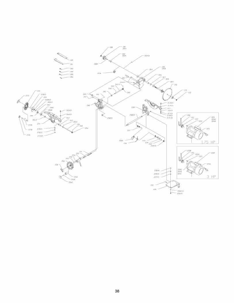
38

39
KEY PARTNO. NO. DESCRIPTION QTY.
200 OR91767 5/8-18 JAM NUT 1
200A OR91824 5x5x15 KEY 1
201 OR91020 ARBOR PULLEY ( 1.75 HP) 1
201A OR70143 ARBOR PULLEY ( 3 HP) 1
202 OR91732 ARBOR SPACER (1.75 HP) 1
202A OR70144 ARBOR SPACER ( 3 HP) 1
203 OR90761 M5X12 PAN HD SCR ( 3 HP) 3
203A OR91734 SPANNER NUT (1.75 HP) 1
204 OR91733 <6203 LLB> BALL BEARING 1
205 OR91004 ELEVATING BRACKET (1.75HP) 1
205A OR70145 ELEVATING BRACKET ( 3 HP ) 1
206 OR91024 ARBOR SLEEVE 1
207 OR91801 <BWW 6203> WAVE WASHER 1
208 OR91733 <6203 LLB> BALL BEARING 1
209 OR91022 ARBOR SHAFT 1
210 OR70146 BLADE 1
211 OR91026 BLADE FLANGE 1
212 OR91050 BLADE HEX NUT-RH 1
213 OR91746 M10 x 45mm HEX HD SCR 2
214 OR90230 M10 FLAT WASHER 2
215 OR91003 REAR BRACKET 1
216 OR90230 M10 FLAT WASHER 2
217 OR90227 M10 LOCK WASHER 2
218 OR90228 M10 HEX NUT 2
219 OR91766 5/8-18 LOCK NUT 2
220 OR91721 BELT (1.75 HP) 1
220A OR70147 BELT ( 3 HP) 1
221 OR90253 M5X12 HEX SOC SET SCR 1
222 OR91023 MOTOR PULLEY (1.75 HP) 1
222A OR70148 MOTOR PULLEY ( 3 HP) 1
223 OR91770 5 x 5 x 36mm KEY 1
224 OR70427 MOTOR ASSEMBLY (1.75 HP) 1
224A OR70149 CAPACITOR ( 300 MFD, 250 VOLT, 1.75 HP) 1
224B OR70150 CAPACITOR ( 35 MFD, 250 VOLT, 1.75 HP) 1
224C OR70428 MOTOR ASSEMBLY ( 3 HP) 1
224D OR70151 CAPACITOR (150 MFD, 250 VOLT, 3 HP) 1
224E OR70152 CAPACITOR (20 MFD, 250 VOLT, 3 HP) 1
224F OR70153 JUNCTION BOX COVER 1
225 OR70374 MOTOR SPEC PLATE (1.75 HP) 1
225A OR70375 MOTOR SPEC PLATE ( 3 HP) 1
226 OR90308 M8 X 30mm HEX HD SCR 4
226A OR90311 M8 FLAT WASHER 4
227 OR90311 M8 FLAT WASHER 4
228 OR91001 MOTOR BRACKET 1
229 OR90248 M8 LOCK WASHER 4
230 OR90307 M8 HEX NUT 4
231 OR91825 8mm X 35mm SPRING PIN (1.75 HP) 1
232 OR91771 1/2-13UNC LOCK NUT 3
233 OR91784 1/2”FLAT WASHER 1
234 OR91802 WAVE WASHER 1
235 OR91054 MOTOR MOUNT STUD 1
236 OR91056 MOTOR SPRING (1.75 HP) 1
236A OR70154 MOTOR SPRING ( 3 HP) 1
237 OR91057 STUD 1
238 OR91053 TIE BAR 2
KEY PARTNO. NO. DESCRIPTION QTY.
239 OR91002 REAR TRUNNION 1
240 OR91790 SHAFT 1
241 OR91757 M5 x 20mm HEX SOC HD SCR 2
242 OR91744 GEAR 1
242A OR91792 3mm x 15mm SPRING PIN 1
243 OR91047 ELEVATING SHAFT 1
244 OR91793 3mm x 20mm SPRING PIN 1
245 OR91767 5/8-18 JAM NUT 1
246 OR90283 M6 X 8mm HEX SOC SET SCR 1
247 OR91757 M5 x 20mm HEX SOC HD SCR 1
248 OR91005 FRONT TRUNNION 1
249 OR91800 WAVE WASHER 1
250 OR91766 5/8-18 LOCK NUT 2
251 OR91028 RAISE/LOWER SHAFT 1
252 OR91029 RAISE/LOWER SPACER 1
253 OR91019 POINTER 1
254 OR90059 M6 FLAT WASHER 1
255 OR91826 M6 X 16mm PAN HD SCR 1
256 OR70155 HANDWHEEL 1
256a OR70156 KNOB 1
256b OR91038 KNOB BOLT 1
256c OR70157 KNOB END CAP 1
258 OR70158 HANDWHEEL LOCK KNOB 1
259 OR91744 GEAR 1
260 OR91792 3mm x 15mm SPRING PIN 1
261 OR91033 TILT SHAFT 1
261A OR91793 3mm X 20mm SPRING PIN 1
262 OR91738 ECCENTRIC 1
263 OR91006 FRONT BRACKET 1
264 OR90230 M10 FLAT WASHER 2
265 OR91746 M10 X 45mm HEX HD SCR 2
266 OR91018 TILT COLLAR 1
266A OR91740 3/8” FIBER WASHER 1
266B OR91137 COLLAR 1
266C OR91762 1/4-20 X 1/4” HEX SOC SET SCR 2
267 OR90283 M6 X 8mm HEX SOC SET SCR 1
268 OR90381 M5 NUT 2
268A OR91827 M5 FLAT WASHER 2
269 OR91017 TILT PLATE 1
270 OR91786 M5 X 25mm PAN HD SCR 2
271 OR70155 HANDWHEEL 1
271a OR70156 KNOB 1
271b OR91038 KNOB BOLT 1
271c OR70157 KNOB END CAP 1
273 OR70158 HANDWHEEL LOCK KNOB 1
274 OR91768 9/16-18 JAM HEX NUT 1
275 OR90230 M10 FLAT WASHER 2
276 OR90227 M10 LOCK WASHER 2
277 OR90228 M10 HEX NUT 2
280 OR91726 WRENCH 1
281 OR91727 OPEN END WRENCH 1
283 OR90290 3mm ALLEN WRENCH 1
284 OR90291 4mm ALLEN WRENCH 1
285 OR91728 5mm ALLEN WRENCH 1
286 OR91808 1/8”ALLEN WRENCH 1

40
KEY PARTNO. NO. DESCRIPTION QTY.
301 OR70159 CABINET ASSY WELDMENT 1
301A OR70322 SPEC TAG (1.75 HP) 1
301B OR70160 BEVEL SCALE 1
301C OR91566 BLADE ELEVATION AND TILT LABEL 1
301D OR70323 SPEC TAG ( 3 HP)
302 OR70161 HINGE ASSY 1
302A OR90381 M5 HEX NUT 4
302B OR90462 M5 FLAT WASHER 4
303 OR91787 1/4-20 x 3/8 PAN HD TAP 3
304 OR70162 MOTOR COVER 1
304A OR91564 WARNING LABEL 1
305 OR91777 M5 X 15mm PAN HEAD SCREW 4
305A OR90462 M5 FLAT WASHER 4
306 OR91058 LATCH BLACK SWELL ASSY 2
307 OR70165 CABINET SIDE PANEL 1
308 OR91787 1/4-20 x 3/8 PAN HD TAP 3
309 OR91787 1/4-20 x 3/8 PAN HD TAP 4
311 OR91124 DUST CHUTE 1
KEY PARTNO. NO. DESCRIPTION QTY.
316 OR91787 1/4-20 x 3/8 PAN HD TAP 1
317 OR91737 CABLE CLAMP 1
318 OR91787 1/4-20 x 3/8 PAN HD TAP 2
319 OR91128 DUST PORT 1
320 OR91833 1/4-20 x 1/2 PAN HD TAP 4
323 OR91787 1/4-20 x 3/8 PAN HD TAP 3
324 OR91106 INSULATOR 1
325 OR70484 NAMEPLATE 1
325A OR93823 RIVET 4
327 OR91134 WRENCH HOOK 1
328 OR91135 FENCE BRACKET 2
329 OR91832 M4 X 8mm PAN HD TAP SCR 2
329A OR90143 M4 FLAT WASHER 2
329B OR91787 1/4-20 x3/8 PAN HD TAP SCR 4
330 OR70131 OWNERS MANUAL (NOT SHOWN) 1
331 OR70163 OWNERS MANUAL FRENCH (NOT SHOWN) 1
332 OR70164 OWNERS MANUAL SPANISH (NOT SHOWN) 1

41

42
u NOTES u

43
5 Year Warranty
STEEL CITYTOOL WORKS
www.steelcitytoolworks.com
u
1-877-SC4-TOOL(1-877-724-8665)
