table of contents - durman · tm what is corzan ® cpvc? 3.1 chlorinated polyvinyl chloride (cpvc)...
TRANSCRIPT

TM
CORZAN GENERAL INFORMATION .............................1.1
CHEMICAL RESISTANCE DATA....................................2.1
PIPING SYSTEMSWhat is Corzan CPVC? . . . . . . . . . . . . . . . . . . . . . . . . 3.1Basic Physical Properties . . . . . . . . . . . . . . . . . . . . . . 3.2Fire Performance Characteristics. . . . . . . . . . . . . . . . 3.7Weatherability . . . . . . . . . . . . . . . . . . . . . . . . . . . . . . 3.9Abrasion Resistance . . . . . . . . . . . . . . . . . . . . . . . . 3.10Biological Resistance. . . . . . . . . . . . . . . . . . . . . . . . 3.11Long-Term Performance ofCorzan Piping Systems Under Pressure . . . . . . . . . 3.12
Design Properties of Pipe. . . . . . . . . . . . . . . . . . . . . 3.13General Specification. . . . . . . . . . . . . . . . . . . . . . . . 3.15
DESIGN DATACorzan Pressure Ratings . . . . . . . . . . . . . . . . . . . . . . 4.1Fluid Handling Characteristics of Corzan Pipe. . . . . . 4.4Carrying Capacity and Friction Loss. . . . . . . . . . . . . . 4.6Thermal Expansion and Thermal Stresses. . . . . . . . . 4.8Typical Recommended Maximum
Support Spacing (in feet) . . . . . . . . . . . . . . . . . . . 4.10Thermal Conductivity of Corzan CPVC . . . . . . . . . . . 4.12General Installation Guidelines . . . . . . . . . . . . . . . . 4.13Joining Corzan Pipe and Fittings -
Solvent Cementing . . . . . . . . . . . . . . . . . . . . . . . . 4.14Threading of Corzan Schedule 80 Pipe . . . . . . . . . . 4.16Flanging of Corzan Pipe . . . . . . . . . . . . . . . . . . . . . . 4.17Back-Welding of Pipe Joints . . . . . . . . . . . . . . . . . . 4.18Underground Installation Guidelines . . . . . . . . . . . . 4.19
DUCTING SYSTEMSCorzan Ducting Systems . . . . . . . . . . . . . . . . . . . . . . 5.1Basic Physical Properties . . . . . . . . . . . . . . . . . . . . . . 5.2Dimensions. . . . . . . . . . . . . . . . . . . . . . . . . . . . . . . . . 5.6Product Ratings and Capability . . . . . . . . . . . . . . . . . 5.7Installation of Corzan Ducting System. . . . . . . . . . . . 5.8Hangers and Supports . . . . . . . . . . . . . . . . . . . . . . . . 5.9
SHEET/LININGIndustrial Sheet/Lining. . . . . . . . . . . . . . . . . . . . . . . . 6.1Basic Physical Properties . . . . . . . . . . . . . . . . . . . . . . 6.2
CUSTOM FABRICATIONRecommendations for Fabrication . . . . . . . . . . . . . . . 7.1High Speed Hot Gas Welding . . . . . . . . . . . . . . . . . . 7.1Hot Plate (Butt) Welding . . . . . . . . . . . . . . . . . . . . . . 7.6Other Fabrication Reference Materials . . . . . . . . . . . 7.8
OTHER SYSTEM COMPONENTSOther System Components . . . . . . . . . . . . . . . . . . . . 8.1
ECONOMIC BENEFITSEconomic Benefits -
A Process Life-Cycle Approach . . . . . . . . . . . . . . . . 9.1
INDUSTRIES/APPLICATIONSIndustries/Applications . . . . . . . . . . . . . . . . . . . . . . 10.1
PRODUCT AVAILABILITYManufacturing Partners/Products . . . . . . . . . . . . . . 11.1Manufacturers of Process Components. . . . . . . . . . 11.2
APPENDICESGlossary . . . . . . . . . . . . . . . . . . . . . . . . . . . . . . . . . . 12.1Conversion Factors. . . . . . . . . . . . . . . . . . . . . . . . . . 12.4
Table of Contents
The information contained herein is believed to be reliable,but no representations, guarantees or warranties of anykind are made as to its accuracy, suitability for particularapplications or the results to be obtained therefrom. Theinformation is based on laboratory work with small-scaleequipment and does not necessarily indicate end productperformance. Because of the variations in methods,
conditions and equipment used commercially in process-ing these materials, no warranties or guarantees are madeas to the suitability of the products for the application disclosed. Full-scale testing and end product performanceare the responsibility of the user. Noveon shall not be liablefor and the customer assumes all risk and liability of anyuse or handling of any material beyond Noveon's direct
control. The SELLER MAKES NO WARRANTIES,EXPRESS OR IMPLIED, INCLUDING, BUT NOT LIMITEDTO, THE IMPLIED WARRANTIES OF MERCHANTABILITYAND FITNESS FOR A PARTICULAR PURPOSE. Nothingcontained herein is to be considered as permission,recommendation, nor as an inducement to practice anypatented invention without permission of the patent owner.
TM Trademark of Noveon IP Holdings Corp. December 2002© Copyright 2002 Noveon, Inc.
Noveon, Inc. / 9911 Brecksville Road, Cleveland, Ohio 44141-3247
**Information presented within this report is based on test data and field experience of CPVC manufactured by Noveon and is not intendedto reflect the properties found with other suppliers of CPVC materials. To determine if your supplier is using Corzan CPVC, call the CorzanMarketing Department at 888-234-2436.

TM
What is Corzan® CPVC?
3.1
Chlorinated polyvinyl chloride (CPVC) has become animportant engineering thermoplastic due to its relativelylow cost, high glass transition temperature, high heatdistortion temperature, chemical inertness, and outstandingmechanical, dielectric, and flame and smoke properties.CPVC was first commercialized by Noveon in the early1960s and has since proven its value in a variety of industrialapplications in which a high use temperature and excellentresistance to corrosive chemicals are desirable. Besidespipe and fittings, many other industrial fluid-handling productsare available in Corzan® CPVC including pumps, valves,strainers, filters, tower packing, and duct, as well as sheetfor fabrication into storage tanks, fume scrubbers, largediameter duct, and tank lining.
Conceptually, CPVC is a PVC homopolymer that has been subjected to a chlorination reaction. Typically,chlorine and PVC react according to a basic free radicalmechanism. This can be brought about by various approachesusing thermal and/or UV energy for initiation of the reaction.A generalized mechanism for the free radical chlorination ofPVC can be schematically represented as follows, where RHdenotes PVC:
HeatInitiation: Cl2 ——————> 2Cl•UV Energy
Propagation: RH + Cl• ————> R• + HClR• + Cl2 ————> RCl + Cl•
Termination: R• + Cl• ————> RClCl• + Cl• —————> Cl2
R• + R• ————> R2
CPVC produced in such a manner can be quite varied structurally depending on the chlorination method,conditions, and the amount of chlorine reacted. The chlorinecontent of base PVC can be increased from 56.7 percent toas high as 74 percent, though typically most commercialCPVC resins have 63 to 69 percent chlorine. As the chlorine content in CPVC is increased, the glass transitiontemperature (Tg) of the polymer increases significantly.Also, as the molecular weight of base PVC is increased,there is a smaller proportionate increase in the Tg at anequivalent level of chlorine.
The CPVC resin manufactured from this free radicalchlorination reaction is not processable without theaddition of additives. These additives may include, but are not limited to, stabilizers (heat and UV), impact modifiers,pigments and lubricants. The quantity and combination ofthese additives enhances many of the CPVC resin’s inherentproperties, while easing its processability.
The family of these various compound formulationscomprises Corzan® CPVC.
PVC CPVC Resin
CPVC Compound
UV & Heat Corzan® CPVC
Cl2 Additives

TM
3.2
Property Test Condition English Units SI Units
GENERAL
Specific Gravity ASTM D792 73°F/23°C 1.55Specific Volume 73°F/23°C .0103 ft3/lb 0.645 cm3/gWater Absorption ASTM D570 73°F/23°C +0.03% +0.03%
212°F/100°C +0.55% +0.55%Rockwell Hardness ASTM D785 73°F/23°C 119Cell class ASTM D1784 23447
MECHANICAL
*Notched Izod Impact ASTM D256 73°F/23°C 1.5 ft lbf/in 80 J/m*Tensile Strength ASTM D638 73°F/23°C 8000 psi 55 N/mm2
*Tensile Modulus ASTM D638 73°F/23°C 360,000 psi 2500 N/mm2
*Flexural Strength ASTM D790 73°F/23°C 15,100 psi 104 N/mm2
*Flexural Modulus ASTM D790 73°F/23°C 415,000 psi 2860 N/mm2
Compressive Strength ASTM D695 73°F/23°C 10,100 psi 70 N/mm2
Compressive Modulus ASTM D695 73°F/23°C 196,000 psi 1350 N/mm2
THERMAL
Coefficient of ASTM D696 3.4x10⁻⁵ in/in/°F 1.9x10⁻⁵ m/m/KThermal Expansion
Thermal Conductivity ASTM C177 0.95 BTU in/hr/ft2/°F 0.066 Wm/K/m2
Heat Distortion Temperature ASTM D648 217°F 103°C*Heat Capacity (Specific Heat) DSC 73°F/23°C 0.21 BTU/lbm °F 0.90 J/gK
212°F/100°C 0.26 BTU/lbm °F 1.10 J/gK
FLAMMABILITY
Flammability Rating UL 94 0.062 in/0.157 cm V-O, 5VB, 5VAFlame Spread ASTM E84 15Smoke Developed ASTM E84 70-125Limiting Oxygen Index ASTM D2863 60%
ELECTRICAL
Dielectric Strength ASTM D147 1250 V/mil 492,000 V/cmDielectric Constant ASTM D150 60 Hz, 30°F/-1°C 3.70 3.70Power Factor ASTM D150 1000 Hz 0.007% 0.007%Volume Resistivity ASTM D257 73°F/23°C 3.4x10¹⁵ ohm/cm 3.4x10¹⁵ ohm/cm
*Plots of these properties versus temperature follow this table.
Basic Physical Properties

TM
Basic Physical Properties (cont.)
3.3
10,000
8,000
6,000
4,000
2,000
0
6560555045403530252015105
20 30 40 50 60 70 80 90
50 75 100 125 150 175 200
Temperature (°C)
Temperature (°F)
Tens
ile S
treng
th (p
si)
Tens
ile S
treng
th (N
/mm
2 )
Tensile Strength
0
50,000
100,000
150,000
200,000
250,000
300,000
350,000
400,000
500
1,000
1,500
2,000
2,500
20 30 40 50 60 70 80 90
50 75 100 125 150 175 200
Temperature (°C)
Temperature (°F)
Tens
ile M
odul
us (p
si)
Tens
ile M
odul
us (N
/mm
2 )Tensile Modulus

TM
3.4
Basic Physical Properties (cont.)
16,000
14,000
12,000
10,000
8,000
6,000
4,000
2,000
0
100
90
80
70
60
50
40
30
20
10
20 30 40 50 60 70 80 90
50 75 100 125 150 175 200
Temperature (°C)
Temperature (°F)
Flexu
ral S
treng
th (p
si)
Flexu
ral S
treng
th (N
/mm
2 )
Flexural Strength
0
50,000
100,000
150,000
200,000
250,000
300,000
350,000
450,000
400,000
500
1,000
1,500
2,000
3,000
2,500
20 30 40 50 60 70 80 90
50 75 100 125 150 175 200
Temperature (°C)
Temperature (°F)
Flexu
ral M
odul
us (p
si)
Flexu
ral M
odul
us (N
/mm
2 )Flexural Modulus

TM
3.5
Basic Physical Properties (cont.)
12,000
10,000
8,000
6,000
4,000
2,000
0
60
70
80
50
40
30
20
10
20 30 40 50 60 70 80 90
50 75 100 125 150 175 200
Temperature (°C)
Temperature (°F)
Com
pres
sive
Stre
ngth
(psi)
Com
pres
sive
Stre
ngth
(N/m
m2 )
Compressive Strength
0
25,000
100,000
75,000
50,000
125,000
150,000
175,000
200,000
225,000
250,000
200
400
600
800
1,000
1,200
1,400
1,600
20 30 40 50 60 70 80 90
50 75 100 125 150 175 200
Temperature (°C)
Temperature (°F)
Com
pres
sive
Mod
ulus
(psi)
Com
pres
sive
Mod
ulus
(N/m
m2 )
Compressive Modulus

TM
3.6
0.660.68
0.720.70
0.740.760.780.800.820.840.860.880.90
8759009259509751,0001,0251,0501,0751,100
1,150403020 50 60 70 80 90 100
70 9080 120110 140 160 170 190 200
Spec
ific H
eat
(BTU
/lbm
° F)
Spec
ific H
eat
(J/k
g °K
)
850
1,125
100 130 150 180 210
Temperature (°C)Specific Heat
Temperature (°F)
Basic Physical Properties (cont.)
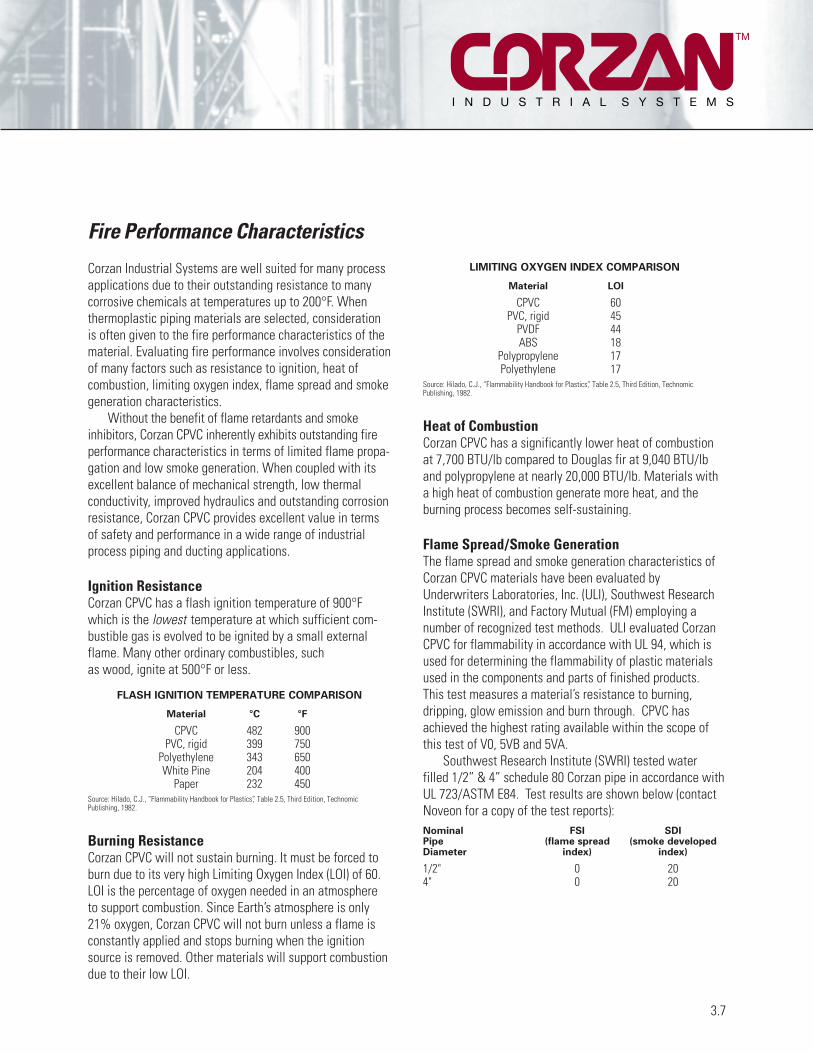
Corzan Industrial Systems are well suited for many processapplications due to their outstanding resistance to manycorrosive chemicals at temperatures up to 200°F. Whenthermoplastic piping materials are selected, considerationis often given to the fire performance characteristics of thematerial. Evaluating fire performance involves considerationof many factors such as resistance to ignition, heat ofcombustion, limiting oxygen index, flame spread and smokegeneration characteristics.
Without the benefit of flame retardants and smokeinhibitors, Corzan CPVC inherently exhibits outstanding fireperformance characteristics in terms of limited flame propa-gation and low smoke generation. When coupled with itsexcellent balance of mechanical strength, low thermalconductivity, improved hydraulics and outstanding corrosionresistance, Corzan CPVC provides excellent value in termsof safety and performance in a wide range of industrialprocess piping and ducting applications.
Ignition ResistanceCorzan CPVC has a flash ignition temperature of 900°Fwhich is the lowest temperature at which sufficient com-bustible gas is evolved to be ignited by a small externalflame. Many other ordinary combustibles, such as wood, ignite at 500°F or less.
FLASH IGNITION TEMPERATURE COMPARISON
Material °C °F
CPVC 482 900PVC, rigid 399 750
Polyethylene 343 650White Pine 204 400
Paper 232 450Source: Hilado, C.J., “Flammability Handbook for Plastics”, Table 2.5, Third Edition, Technomic Publishing, 1982.
Burning ResistanceCorzan CPVC will not sustain burning. It must be forced toburn due to its very high Limiting Oxygen Index (LOI) of 60.LOI is the percentage of oxygen needed in an atmosphere to support combustion. Since Earth’s atmosphere is only21% oxygen, Corzan CPVC will not burn unless a flame isconstantly applied and stops burning when the ignitionsource is removed. Other materials will support combustiondue to their low LOI.
LIMITING OXYGEN INDEX COMPARISON
Material LOI
CPVC 60PVC, rigid 45
PVDF 44ABS 18
Polypropylene 17Polyethylene 17
Source: Hilado, C.J., “Flammability Handbook for Plastics”, Table 2.5, Third Edition, TechnomicPublishing, 1982.
Heat of CombustionCorzan CPVC has a significantly lower heat of combustionat 7,700 BTU/lb compared to Douglas fir at 9,040 BTU/lband polypropylene at nearly 20,000 BTU/lb. Materials witha high heat of combustion generate more heat, and theburning process becomes self-sustaining.
Flame Spread/Smoke GenerationThe flame spread and smoke generation characteristics ofCorzan CPVC materials have been evaluated byUnderwriters Laboratories, Inc. (ULI), Southwest ResearchInstitute (SWRI), and Factory Mutual (FM) employing a number of recognized test methods. ULI evaluated CorzanCPVC for flammability in accordance with UL 94, which isused for determining the flammability of plastic materialsused in the components and parts of finished products.This test measures a material’s resistance to burning, dripping, glow emission and burn through. CPVC hasachieved the highest rating available within the scope ofthis test of V0, 5VB and 5VA.
Southwest Research Institute (SWRI) tested water filled 1/2” & 4” schedule 80 Corzan pipe in accordance withUL 723/ASTM E84. Test results are shown below (contactNoveon for a copy of the test reports):Nominal FSI SDIPipe (flame spread (smoke developedDiameter index) index)
1/2" 0 204" 0 20
3.7
Fire Performance Characteristics
TM

TM
Fire Performance Characteristics (cont.)
Factory Mutual Clean Room MaterialsFlammability Testing Protocol (FM 4910)Due to the growing concern in the semiconductor industryover safety and the high cost associated with fires and thesubsequent cleanup, Factory Mutual developed a standard (FM 4910) for semiconductor clean roommaterials that requires that these materials provide greaterresistance to flame and smoke development and thereforelimit the damage that can be caused by fires. SeveralCorzan CPVC compounds have been evaluated and pass the FM 4910 test protocol for fire propagation & smokedevelopment. These compounds include gray ductcompound (for manufacture into seamless, round extruded duct), gray pipe compound, and the Corzan 4910compounds, which are used to manufacture sheet for fabrication into cleanroom equipment.
3.8
Corzan 4910 CPVC sheet materials are a cost effectivemeans for meeting the FM 4910 requirements forcleanroom tool construction. Compared to less expensive,non-fire safe materials such as polypropylene (PP) andflame-retardant polypropylene (FR-PP), Corzan 4910 CPVCmay not require additional fire suppression equipment,lowering the overall cost of ownership of cleanroom tools.
Independent ListingsIn some cases, the manufacturer of Corzan CPVC finishedproducts will perform the testing required to obtain a product listing independent of Noveon. Consult themanufacturer to obtain these listings.

Weatherability is defined as a material’s ability to maintainits basic physical properties after prolonged exposure to sunlight, wind, and rain/humidity. Over 40 years ofexperience with CPVC, including many long-standingoutdoor installations, demonstrate that Corzan IndustrialSystems will be able to withstand long-term exposure tothe environment without significant adverse effects.
Corzan CPVC has been blended with a significantconcentration of both carbon black and titanium dioxide(TiO2). Both carbon black and TiO2 are widely recognized asexcellent ultraviolet blocking agents and help to protect thepolymer backbone from the effects of ultraviolet radiation.
In fact, Noveon experience verifies that the pressurebearing capability of Corzan piping systems is maintainedafter extended exposure. Depending on the specificinstallation, there has been some gradual reduction inimpact properties with prolonged exposure. If the specificinstallation requires additional protection from UVexposure, Corzan piping systems can be painted withcommon acrylic latex paint. Priming of the piping is not necessary prior to painting.
3.9
Weatherability
TM

A piping system’s resistance to abrasion is a function ofmany factors:
• Particle size and shape• Hardness of particles• Particle concentration• Densities (fluid, particle, and pipe)• Velocities• Properties of piping materials• Design of the piping system
While all piping systems will exhibit some degree ofwear over time, the actual erosion will depend on thespecific combination of these factors. Excluding the pipingmaterial itself, the system conditions which will minimizeabrasion include:
• Lower velocities (<5 ft/sec)• Large, round particles• Uniform particle distribution• Minimum changes in direction
When these ideal slurry conditions do not exist, the selection of the piping material becomes important.Corzan piping systems will usually outperform metal when transporting abrasive media and have been usedsuccessfully in many abrasive industrial applications.
No single test method exists which can consistentlypredict the abrasion resistance of a material to the broadrange of potentially abrasive conditions. As a result, thebest guide in selecting materials for abrasive service is pastexperience. In lieu of such case histories, attention shouldbe directed towards approaching the ideal system conditionsmentioned above, particularly minimizing changes indirection. At the same time, changes in direction can bedesigned to minimize abrasion potential. Large radiuselbows and capped tee bends are usually specified toreduce particle impingement on the pipe wall.
One widely referenced test method is the Taber AbrasionTest, in which the weight loss of a material is measuredafter being exposed to an abrasive wheel for 1000 cycles.While the Taber test cannot predict actual performance of a material to a given application, it does provide a relativemeasure to compare materials.
TABER ABRASION TESTER
(Abrasion Ring CS-10, Load 1 kg)
Nylon 6-10 5mg/1000 cyclesUHMW PE 5
PVDF 5-10PVC (rigid) 12-20
PP 15-20CPVC 20CTFE 13PS 40-50
Steel (304 SS) 50ABS 60-80PTFE 500-1000
Source: Industrial and High Purity Piping Systems Engineering Handbook, George Fischer +GF+, 2002.
3.10
Abrasion Resistance
TM

Corzan piping systems are resistant to attack from fungi.Fungus growth on plastics is supported when plasticizers or other additives are present for the fungus to feed on.Corzan CPVC contains no additives which would provide anutrient source for fungi.
Bacteria are encountered in nearly all situations wherewater is present. The smooth interior surface of Corzanpiping provides fewer footholds for bacteria to take hold
and multiply. Corzan piping systems are resistant to theaction of all forms of bacteria, many of which are known to cause corrosion in metal piping systems, such as iron-oxidizing bacteria, sulfate-reducing bacteria, and acid-producing bacteria.
Corzan CPVC is also resistant to most commonly usedbiocidal chemicals.
3.11
Biological Resistance
TM

The long term performance of Corzan piping systems underpressure is tested in accordance with ASTM D 1598, TestMethod for Time-to-Failure of Plastic Pipe Under ConstantInternal Pressure. Typical data obtained from pipe madefrom Corzan CPVC is shown below. Data is obtained up to16,000 hours. The data is evaluated in accordance withASTM D 2837, Standard Method for Obtaining HydrostaticDesign Basis for Thermoplastic Pipe Materials. Thehydrostatic design basis (HDB) is the extrapolated value
of the hoop stress at 100,000 hours. The hydrostatic designstress (HDS) is taken as 50% of the HDB. The pressureratings for specific pipe sizes are calculated from the HDSwith the following formula:
P= 2StD-t
where: P = pipe pressure ratingS = hydrostatic design stress (HDS)t = pipe wall thicknessD = pipe outside diameter
3.12
Long-Term Performance of Corzan Piping Systems Under Pressure
TM
10,000
1,000
Time to Failure (Years)
Hoop
Stre
ss (p
si)
Long-Term Performance of Corzan CPVC
1 2010 50
73°F/ 23°C
180°F/82°C

The data in the following tables can be used by pipingdesign engineers to estimate loads, stresses, torques, and other mechanical data.
Definitions and Derivations
t: Minimum wall thickness of the pipe in inches asspecified by ASTM F441 – Standard Specification forChlorinated Poly(Vinyl Chloride) (CPVC) Plastic Pipe,Schedules 40 and 80
D: Outside diameter of the pipe in inches as specified byASTM F441
d: Average inside diameter of the pipe in inches calculated by considering the average wall thicknessto be the minimum wall thickness plus half thetolerance allowed by ASTM F441. All the values in the following tables are calculated with the averageinside diameter, not the minimum wall thickness.
Ao: Outside surface area of the pipe in square feet per foot:
Ao= �D12
A i: Inside surface area of the pipe in square feet per foot:
A i= �D12
Aw: Cross-sectional area of the pipe wall in squareinches:
Aw= �(D2-d2)4
Af: Cross-sectional area of flow in pipe in square inches:
Af= �d2
4
W: Average weight of pipe in pounds per foot:
W=0.671Aw
Ww: Average weight of water in pipe in pounds per foot:
Ww=0.433Af
KA: Radius of gyration about the longitudinal axis of thepipe, in inches:
KA= �D2+d2
4
IA: Moment of inertia in inches to the fourth power, (in4):
IA= �(D4-d4)64
3.13
Design Properties of Pipe
TM

TM
Schedule 80Aw Af
t d D Ao Ai Cross Cross W Ww KAMinimum Average Outside Inside Sectional Sectional Average Average Axial IA
Nominal Wall Inside Outside Surface Surface Area of Area of Weight Weight Radius MomentPipe Size Thickness Diameter Diameter Area Area Pipe Wall Flow of Pipe of Water of Gyration of Inertia
(in) (in) (in) (in) (ft2/ft) (ft2/ft) (in2) (in2) (lb/ft) (lb/ft) (in) (in4)
1/4 0.119 0.288 0.540 0.141 0.075 0.164 0.065 0.110 0.028 0.153 0.0038343/8 0.126 0.407 0.675 0.177 0.106 0.228 0.130 0.153 0.056 0.197 0.008841/2 0.147 0.528 0.840 0.220 0.138 0.335 0.219 0.225 0.095 0.248 0.02063/4 0.154 0.724 1.050 0.275 0.189 0.454 0.411 0.305 0.178 0.319 0.04621 0.179 0.935 1.315 0.344 0.245 0.671 0.686 0.450 0.297 0.403 0.109
1 1/4 0.191 1.256 1.660 0.434 0.329 0.925 1.238 0.621 0.536 0.520 0.2501 1/2 0.200 1.476 1.900 0.497 0.386 1.124 1.710 0.754 0.741 0.601 0.407
2 0.218 1.913 2.375 0.621 0.501 1.555 2.873 1.043 1.244 0.762 0.9042 1/2 0.276 2.289 2.875 0.752 0.599 2.375 4.113 1.594 1.781 0.919 2.005
3 0.300 2.864 3.500 0.916 0.749 3.177 6.439 2.132 2.788 1.131 4.0614 0.337 3.786 4.500 1.178 0.991 4.644 11.252 3.116 4.872 1.470 10.0386 0.432 5.709 6.625 1.734 1.494 8.869 25.585 5.951 11.078 2.186 42.408 0.500 7.565 8.625 2.257 1.980 13.472 44.925 9.040 19.452 2.868 110.810 0.593 9.492 10.750 2.813 2.484 19.990 70.727 13.413 30.625 3.585 256.912 0.687 11.294 12.750 3.336 2.955 27.481 100.130 18.440 43.356 4.258 498.314 0.750 12.410 14.000 3.663 3.247 32.964 120.896 22.119 52.348 4.677 721.116 0.843 14.214 16.000 4.187 3.719 42.360 158.600 28.424 68.674 5.350 1212.7
Schedule 40Aw Af
t d D Ao Ai Cross Cross W Ww KAMinimum Average Outside Inside Sectional Sectional Average Average Axial IA
Nominal Wall Inside Outside Surface Surface Area of Area of Weight Weight Radius MomentPipe Size Thickness Diameter Diameter Area Area Pipe Wall Flow of Pipe of Water of Gyration of Inertia
(in) (in) (in) (in) (ft2/ft) (ft2/ft) (in2) (in2) (lb/ft) (lb/ft) (in) (in4)
1/4 0.088 0.354 0.540 0.141 0.093 0.131 0.098 0.088 0.043 0.161 0.003403/8 0.091 0.483 0.675 0.177 0.126 0.175 0.183 0.117 0.079 0.208 0.007511/2 0.109 0.608 0.840 0.220 0.159 0.264 0.290 0.177 0.126 0.259 0.017723/4 0.113 0.810 1.050 0.275 0.212 0.350 0.515 0.235 0.223 0.332 0.038521 0.133 1.033 1.315 0.344 0.270 0.520 0.838 0.349 0.363 0.418 0.09084
1 1/4 0.140 1.364 1.660 0.434 0.357 0.703 1.460 0.471 0.632 0.537 0.202721 1/2 0.145 1.592 1.900 0.497 0.417 0.844 1.990 0.567 0.861 0.620 0.32423
2 0.154 2.049 2.375 0.621 0.536 1.132 3.296 0.760 1.427 0.784 0.69622 1/2 0.203 2.445 2.875 0.752 0.640 1.796 4.693 1.205 2.032 0.944 1.5986
3 0.216 3.042 3.500 0.916 0.796 2.352 7.264 1.578 3.145 1.159 3.16114 0.237 3.998 4.500 1.178 1.046 3.349 12.547 2.247 5.433 1.505 7.58386 0.280 6.031 6.625 1.734 1.578 5.901 28.553 3.960 12.363 2.240 29.6048 0.322 7.943 8.625 2.257 2.078 8.870 49.527 5.952 21.445 2.931 76.2210 0.365 9.976 10.750 2.813 2.610 12.593 78.124 8.450 33.828 3.666 169.2812 0.406 11.890 12.750 3.336 3.111 16.634 110.977 11.162 48.053 4.358 315.9914 0.437 13.072 14.000 3.663 3.421 19.721 134.139 13.233 58.082 4.789 452.2116 0.500 14.940 16.000 4.187 3.909 25.745 175.215 17.275 75.868 5.473 771.07
3.14
Design Properties of Pipe (cont.)

Corzan® CPVC Pipe and Fittings1.0 Product DescriptionCorzan® CPVC pipe and fittings are extruded/molded fromCPVC compounds manufactured by Noveon, Inc. The compounds shall meet cell class 23447 as defined by ASTMD1784, and the pipe shall be certified by NSF Internationalfor use with potable water. Corrosion resistant Corzan pipeand fittings are available in iron pipe sizes (IPS) for use inboth pressure bearing and drain applications at temperaturesup to and including 200°F. Pressure rating varies with schedule, pipe size, and temperature. See temperature derating chart for derating factors. Chemical resistancedata is available and should be referenced for proper material selection.
1.1 Pipe and Fittings Dimensions and TolerancesA. Schedules 40 and 80 pipe shall meet or exceed the
requirements of ASTM F441.B. Fittings shall meet or exceed the requirements of ASTM
F437 (schedule 80 threaded), ASTM F438 (schedule 40 socket) and ASTM F439 (schedule 80 socket).
1.2 Solvent CementAll socket type joints shall be made employing solventcements that meet or exceed the requirements of ASTMF493 and primers that meet or exceed the requirements ofASTM F656. The standard practice for safe handling of solvent cements shall be in accordance with ASTM F402.Solvent cement and primer shall be listed by NSF for usewith potable water, and approved by the Corzan CPVC pipeand fitting manufacturers.
2.0 ManufacturersThe piping systems shall be constructed from materialsextruded/molded/fabricated by manufacturers using CorzanCPVC compounds.
A. PipeCharlotte Pipe & Foundry Co.P.O. Box 35430Charlotte, NC 28235Phone: (800) 438-6091Fax: (800) 553-1605
Harvel Plastics, Inc.P.O. Box 757Easton, PA 18044-0757Phone: (610) 252-7355Fax : (610) 253-4436
IPEX: (US inquiries)PO Box 240696-069610100 Rodney StreetPineville, NC 28134Phone: (800) 463-9572Fax: (905) 403-9195
IPEX (US inquiries)2441 Royal Windsor DriveMississauga, ON L5J 4C7CanadaPhone: (800) 463-9572Fax: (905) 403-9195
IPEX (Canadian inquiries)6810 Invader CrescentMississauga, ON L5T 2B6CanadaPhone: (866) 473-9472Fax: (905) 670-5295
3.15
General Specification
TM
B. FittingsCharlotte Pipe & Foundry Co.P.O. Box 35430Charlotte, NC 28235Phone: (800) 438-6091Fax: (800) 553-1605
IPEX (US inquiries)PO Box 240696-069610100 Rodney StreetPineville, NC 28134Phone: (800) 463-9572Fax: (905) 403-9195
Nibco, Inc.1516 Middlebury StreetP.O. Box 1167Elkhart, IN 46516-4740Phone: (800) 642-5463Fax: (219) 295-3307
Colonial Engineering8132 Merchants PlaceKalamazoo, MI 49002Phone: (800) 374-0234Fax: (616) 323-0630
IPEX (Canadian inquiries)6810 Invader CrescentMississauga, ON L5T 2B6CanadaPhone: (866) 473-9472Fax: (905) 670-5295

3.16
TM
C. ValvesCEPEX USA, Inc.8003 Westside Industrial Dr.Jacksonville, FL 32219Phone: (904) 695-1441Fax: (904) 695-1442
Hayward Industrial ProductsOne Hayward Industrial Dr.Clemmons, NC 27012-5100Phone: (800) 910-2536Fax: (336) 712-9523
IPEX (Canadian inquiries)6810 Invader CrescentMississauga, ON L5T 2B6CanadaPhone: (866) 473-9472Fax: (905) 670-5295
Plast-O-Matic Valves, Inc.1384 Pompton AvenueCedar Grove, NJ 07009Phone: (973) 256-3000Fax: (973) 256-4745
Colonial Engineering8132 Merchants PlaceKalamazoo, MI 49002Phone: (800) 374-0234Fax: (616) 323-0630
IPEX (US inquiries)PO Box 240696-069610100 Rodney StreetPineville, NC 28134Phone: (800) 463-9572Fax: (905) 403-9195
IPEX (US inquiries)2441 Royal Windsor DriveMississauga, ON L5J 4C7CanadaPhone: (800) 463-9572Fax: (905) 403-9195
Nibco, Inc.1516 Middlebury StreetP.O. Box 1167Elkhart, IN 46516-4740Phone: (800) 642-5463
Plastinetics439 Main Road (Rt. 202)Towaco, NJ 07082Phone (800) 627-7473Fax (973) 316-0300
New Plastics Fitting20W267 101st Street Unit BLemont, IL 60439Phone (630) 739-2600Fax (630) 739-2727
Harrison Machine & Plastics11614 State Route 88Garrettsville, OH 44231Phone (330) 527-5641Fax (330) 527-5640
General Specification (cont.)
D. Solvent CementIPS Corporation455 W. Victoria StreetCompton, CA 90220Phone: (800) 421-2677Fax: (310) 898-3390
E. Fabricated FittingsFabricated fittings shall be manufactured by heat fusion(hot plate or hot gas welding) and fiberglass over wrapped.Fabricated fittings shall be manufactured from pipe suppliedby the manufacturers listed in section 2.0A. Parts shall bemanufactured by:

3.0 SYSTEM DESIGNA. System design shall be in accordance with the
manufacturer’s instructions. The design shall take into consideration such factors as pressure and flow requirements, friction loss, operating temperatures, supportspacing, anchoring, bracing and thrust blocking, joiningmethods, and thermal expansion and contraction.
B. Maximum design pressure ratings shall not exceed those listed in the tables below. Pressure ratings apply to water at 73°F. For temperatures greater than 73°F, see derating factors listed. For fluids other than water,the full pressure rating may not apply; see the chemicalresistance table for guidelines.
C. Schedule 80 pipe operating above 130°F shall NOT be threaded.
D. Threaded systems shall be derated to 50% of the pressure rating for the piping at the system operatingtemperature.
E. Flanged systems of any size shall not exceed 150 psiworking pressure at 73°F. Follow the manufacturer’s
recommendations for temperature derating factors forservices greater than 73°F.
F. Corzan valves are typically rated at 150 psi up to 240 psiat 73°F (pressure rating varies with valve type and manufacturer). Consult the valve manufacturer for pressure ratings and temperature derating schedules.
G. A Hazen-Williams friction factor of 150 shall be used in all hydraulic calculations.
TM
Schedule 80Nominal Maximum
Nominal Pipe Minimum Ave Weight Water PSize (in) O.D. wall I.D. (lbs/ft) @73°F
1⁄4” 0.540 0.119 0.288 0.110 11303⁄8” 0.675 0.126 0.407 0.153 9201⁄2” 0.840 0.147 0.528 0.225 8503⁄4” 1.050 0.154 0.724 0.305 6901” 1.315 0.179 0.935 0.450 630
11⁄4” 1.660 0.191 1.256 0.621 52011⁄2” 1.900 0.200 1.476 0.754 4702” 2.375 0.218 1.913 1.043 400
21⁄2” 2.875 0.276 2.289 1.594 4203” 3.500 0.300 2.864 2.132 3704” 4.500 0.337 3.786 3.116 3206” 6.625 0.432 5.709 5.951 2808” 8.625 0.500 7.565 9.040 25010” 10.750 0.593 9.492 13.413 23012” 12.750 0.687 11.294 18.440 23014” 14.000 0.750 12.410 22.119 22016” 16.000 0.843 14.214 28.424 220
3.17
General Specification (cont.)
Schedule 40Nominal Maximum
Nominal Pipe Minimum Average Weight Water PSize (in) O.D. Wall I.D. (lbs/ft) @ 73°F
1⁄4” 0.540 0.088 0.354 0.088 7803⁄8” 0.675 0.091 0.483 0.117 6201⁄2” 0.840 0.109 0.608 0.177 6003⁄4” 1.050 0.113 0.810 0.235 4801” 1.315 0.133 1.033 0.349 450
11⁄4” 1.660 0.140 1.364 0.471 37011⁄2” 1.990 0.145 1.592 0.567 3302” 2.375 0.154 2.049 0.760 280
21⁄2” 2.875 0.203 2.445 1.205 3003” 3.500 0.216 3.042 1.578 2604” 4.500 0.237 3.998 2.247 2206” 6.625 0.280 6.031 3.960 1808” 8.625 0.322 7.943 5.952 16010” 10.750 0.365 9.976 8.450 14012” 12.750 0.406 11.890 11.162 13014” 14.000 0.437 13.072 13.233 13016” 16.000 0.500 14.940 17.275 130
TEMPERATURE DERATING FACTORS (PIPE)
PipeWorking Derating
Temperature (°F) Factor
73-80 1.0090 0.91100 0.82120 0.65140 0.50160 0.40180 0.25200 0.20
Corzan Pipe Dimensions and Pressure Ratings

4.0 JOINING SYSTEMSA. Assembly of pipe and fittings shall be done by solvent
cementing, threading, or flanging.
B. Solvent cement that meets or exceeds the requirementsof ASTM F493 shall be used in conjunction with a primer manufactured by companies listed under section 2.0D.
C. Flanges shall be installed on pipe ends with primer and solvent cement and then bolted together per themanufacturer’s instructions and torque ratings.
D. Threading shall be performed on Schedule 80 pipe 4" and smaller, per the manufacturer’s instructions. Only water soluble oil or water shall be used when threading pipe. Degreasing type solvents shall never be used to clean threads.
E. Only Teflon tape or CPVC compatible pipe dope shall be used when making plastic threaded connections. Noveon maintains a list of products that have been shown to be incompatible with CPVC piping systems. Chemically incompatible products are added to this list as they are brought to Noveon’s attention. For the most current list of chemically incompatible products, contactNoveon or refer to the website, www.corzancpvc.com.A product’s absence from this list does not implyor ensure CPVC chemical compatibility. Always confirm chemical compatibility with CPVC with the manufacturer of the product in contact with the CPVC piping system.
3.18
TM
MAXIMUM SUPPORT SPACING (FEET) SCHEDULE 80Support spacing recommendations are based on straight runs of uninsulated lines conveying fluids with specific gravities up to1.0. Heavy system components such as valves, flanged assemblies, tees and other forms of concentrated stress loads must beindependently supported. For specific gravities greater than 1.0, the support spacing from the table provided should be multiplied by the following correction factors:
Specific Gravity 1.0 1.1 1.2 1.4 1.6 2.0 2.5
Correction Factor 1.00 0.98 0.96 0.93 0.90 0.85 0.80
Temp (F) 1⁄2” 1⁄4” 1” 11⁄4” 11⁄2” 2” 21⁄2” 3” 4” 6” 8” 10” 12” 14" 16"
73 51⁄2 51⁄2 6 61⁄2 7 7 8 8 9 10 11 111⁄2 121⁄2 15 16100 5 51⁄2 6 6 61⁄2 7 71⁄2 8 9 91⁄2 101⁄2 11 121⁄2 131⁄2 15120 41⁄2 5 51⁄2 6 6 61⁄2 71⁄2 71⁄2 81⁄2 9 10 101⁄2 11 121⁄2 131⁄2
140 41⁄2 41⁄2 5 51⁄2 51⁄2 6 61⁄2 7 71⁄2 8 9 91⁄2 101⁄2 11 12160 3 3 31⁄2 31⁄2 31⁄2 4 41⁄2 41⁄2 5 51⁄2 6 61⁄2 71⁄2 91⁄2 10180 21⁄2 21⁄2 3 3 31⁄2 31⁄2 4 4 41⁄2 5 51⁄2 6 61⁄2 8 81⁄2
MAXIMUM SUPPORT SPACING (FEET) SCHEDULE 40
Temp (F) 1⁄2” 1⁄4” 1” 11⁄4” 11⁄2” 2” 21⁄2” 3” 4” 6” 8” 10” 12” 14" 16"
60 5 51⁄2 6 6 61⁄2 61⁄2 71⁄2 8 81⁄2 91⁄2 91⁄2 10 101⁄2 12 1380 5 5 51⁄2 51⁄2 61⁄2 6 7 7 71⁄2 81⁄2 81⁄2 91⁄2 101⁄2 11 12
100 41⁄2 5 51⁄2 51⁄2 61⁄2 6 7 7 71⁄2 8 8 9 10 10 11120 41⁄2 41⁄2 5 51⁄2 51⁄2 51⁄2 61⁄2 7 7 71⁄2 71⁄2 8 9 9 91⁄2
140 4 4 41⁄2 5 5 5 6 6 61⁄2 7 7 71⁄2 8 8 81⁄2
180 21⁄2 21⁄2 21⁄2 3 3 3 31⁄2 31⁄2 4 41⁄2 5 51⁄2 6 61⁄4 7
General Specification (cont.)

5.0 APPLICABLE STANDARDSA. ASTM D1784, Specification for Rigid Poly(Vinyl Chloride)
Compounds and Chlorinated Poly(Vinyl Chloride) (CPVC) Compounds
B. ASTM D2855, Standard Practice for Making Solvent Cemented Joints and Poly(Vinyl Chloride) (PVC) Pipe and Fittings.
C. ASTM F402, Standard Practice for Safe Handling of Solvent Cements, Primers, and Cleaners Used for Joining Thermoplastic Pipe and Fittings.
D. ASTM F437, Standard Specification for Threaded Chlorinated Poly(Vinyl Chloride) (CPVC) Plastic Pipe Fittings, Schedule 80.
E. ASTM F438, Standard Specification for Socket-Type Chlorinated Poly(Vinyl Chloride) (CPVC) Plastic Pipe Fittings, Schedule 40.
F. ASTM F439, Standard Specification for Chlorinated Poly(Vinyl Chloride) (CPVC) Plastic Pipe Fittings, Schedule 80.
G. ASTM F441, Standard Specification for Chlorinated Poly(Vinyl Chloride) (CPVC) Plastic Pipe, Schedules 40 & 80.
H. ASTM F493, Standard Specification for Solvent Cements for Chlorinated Poly(Vinyl Chloride) (CPVC) Plastic Pipe and Fittings.
I. ASTM F656, Standard Specification for Primers for Use in Solvent Cement Joints in Poly(Vinyl Chloride) (PVC) Plastic Pipe and Fittings.
J. NSF Standard 14, Plastic Piping Components and Related Materials.
K. NSF Standard 61, Drinking Water System Components – Health Effects.
L. ASTM F493, Standard Specification for Solvent
M. FM4910, Factory Mutual Research Clean RoomMaterials Flammability Test Protocol
6.0 TESTINGAfter the system is installed and any solvent cement is cured, the system shall be hydrostatically tested. Air or compressed gas shall NEVER be used for pressure testing Corzan® CPVC piping systems.
3.19
General Specification (cont.)
TM

4.1
TM
Schedule 80 CPVC (with socket fittings): Water Pressure Rating (psi)PipeSize 70°F 80°F 90°F 100°F 120°F 140°F 160°F 180°F 200°F
1⁄4" 1,130 1,130 1,028 927 735 565 452 283 2263⁄8" 920 920 837 754 598 460 368 230 1841⁄2" 850 850 774 697 553 425 340 213 1703⁄4" 690 690 628 566 449 345 276 173 1381" 630 630 573 517 410 315 252 158 126
11⁄4" 520 520 473 426 338 260 208 130 10411⁄2" 470 470 428 385 306 235 188 118 942" 400 400 364 328 260 200 160 100 80
21⁄2" 420 420 382 344 273 210 168 105 843" 370 370 337 303 241 185 148 93 744" 320 320 291 262 208 160 128 80 645" 290 290 264 238 189 145 116 73 586" 280 280 255 230 182 140 112 70 568" 250 250 228 205 163 125 100 63 5010" 230 230 209 189 150 115 92 58 4612" 230 230 209 189 150 115 92 58 4614" 220 220 200 180 143 110 88 55 4416" 220 220 200 180 143 110 88 55 44
Schedule 40 CPVC (with socket fittings): Water Pressure Rating (psi)PipeSize 70°F 80°F 90°F 100°F 120°F 140°F 160°F 180°F 200°F
1⁄4" 780 780 710 640 507 390 312 195 1563⁄8" 620 620 564 508 403 310 248 155 1241⁄2" 590 590 537 484 384 295 236 148 1183⁄4" 480 480 437 394 312 240 192 120 961" 450 450 410 369 293 225 180 113 90
11⁄4" 365 365 322 299 237 183 146 91 7311⁄2" 330 330 300 271 215 165 132 83 662" 275 275 250 226 179 138 110 69 55
21⁄2" 300 300 273 246 195 150 120 75 603" 260 260 237 213 169 130 104 65 524" 220 220 200 180 143 110 88 55 446" 180 180 164 148 117 90 72 45 368" 160 160 146 131 104 80 64 40 3210" 140 140 127 115 91 70 56 35 2812" 130 130 118 107 85 65 52 33 2614" 130 130 118 107 85 65 52 33 2616" 130 130 118 107 85 65 52 33 26
Corzan Pressure Ratings

TM
Corzan Pressure Ratings (cont.)
4.2
1/4"
1/2"
1"
600
800
1000
1200
400
200
0
Max
imum
Wor
king
Pres
sure
(psi)
Maximum Working Pressure vs. Temperature for Corzan Schedule 80 Piping Systems
180 200160140120100908070
2"
4"
12"
Temperature (°F)
14" & 16"
Corzan® CPVC
PP
PVDF
PVC
PE
0
50
100
150
200
250
300
350
Max
imum
Wor
king
Pres
sure
(psi)
Maximum Working Pressures of 6 Inch Diameter Schedule 80 Lines
80 100 120 140 160 180 200
Temperature (°F)

4.3
TM
Schedule 40Nominal Pipe
Size (in) 73°F 100°F 120°F 140°F 160°F 180°F 200°F1⁄2 1,605 1,386 1,167 1,021 876 803 5843⁄4 1,219 1,153 993 869 745 683 4961 948 896 859 814 698 640 465
11⁄4 511 484 463 443 429 411 39511⁄2 366 346 331 317 307 294 2822 213 201 193 184 179 171 164
21⁄2 276 261 250 238 231 221 2133 179 169 162 155 150 144 1384 108 102 97 93 90 86 836 54 51 49 47 45 43 428 37 35 33 32 31 29 2810 27 26 25 24 23 22 2112 22 21 20 19 19 18 17
Schedule 80Nominal Pipe
Size (in) 73°F 100°F 120°F 140°F 160°F 180°F 200°F1⁄2 2,006 1,732 1,459 1,277 1,094 1,003 7293⁄4 1,740 1,502 1,265 1,107 949 870 6331 1,628 1,406 1,184 1,036 888 814 592
11⁄4 1,399 1,221 1,028 900 771 707 51411⁄2 1,034 978 937 833 714 654 4762 653 617 591 565 548 524 421
21⁄2 758 717 687 656 636 603 4393 521 493 472 451 437 418 3964 334 316 303 289 280 268 2586 214 202 194 185 179 172 1658 146 139 133 127 123 118 113
10 125 118 113 108 105 100 9612 116 110 105 100 97 93 89
Corzan Pressure Ratings (cont.)
Collapse Pressure Rating (PSI)

Linear Fluid Flow VelocityThe linear velocity of a flowing fluid in a pipe is calculatedfrom:
V=0.4085gd2
where V = linear fluid flow velocity in feet per secondg = flow rate in gallons per minuted = inside diameter of pipe in inches
The values in the following tables are based on thisformula. These values are accurate for all fluids.
Linear fluid flow velocity in a system should generallybe limited to 5 ft/s, particularly for pipe sizes 6” and greater.Following this guideline will minimize risk of hydraulic shockdamage due to water hammer surge pressures.
Friction Loss in PipeA great advantage that Corzan pipe enjoys over its metalliccompetitors is a smooth inner surface which is resistant toscaling and fouling. This means that friction pressure lossesin the fluid flow are minimized from the beginning and donot significantly increase as the system ages, as can be thecase with metal pipes subject to scaling.
The Hazen-Williams formula is the generally acceptedmethod of calculating friction head losses in piping systems.The values in the following fluid flow tables are based onthis formula and a surface roughness constant of C =150 forCorzan pipe. Surface roughness constants for other pipingmaterials are given below:
f=0.2083 x (100)1.852 g1.852
C d4.8655
where f = friction head in feet of water per 100 feet of pipe
d = inside diameter of pipe in inchesg = flow rate in gallons per minuteC = pipe surface roughness constant
Constant (C) Type of Pipe
150 CPVC pipe, new-40 years old130-140 steel/cast iron pipe, new
125 steel pipe, old120 cast iron, 4-12 years old110 galvanized steel;
cast iron, 13-20 years old60-80 cast iron, worn/pitted
Friction Loss in FittingsFriction losses through fittings are calculated from theequivalent length of straight pipe which would produce thesame friction loss in the fluid. The equivalent lengths ofpipe for common fittings are given below.
EQUIVALENT LENGTH OF PIPE (FEET)*
90° 45° Standard StandardNominal Standard Standard Tee TeeSize (in) Elbow Elbow Run Flow Branch Flow
1⁄2 1.5 0.8 1.0 4.03⁄4 2.0 1.1 1.4 5.01 2.6 1.4 1.7 6.0
11⁄4 3.8 1.8 2.3 7.011⁄2 4.0 2.1 2.7 8.12 5.7 2.7 4.3 12.0
21⁄2 6.9 3.3 5.1 14.73 7.9 4.1 6.2 16.34 11.4 5.3 8.3 22.06 16.7 8.0 12.5 32.28 21.0 10.6 16.5 39.710 25.1 13.4 19.1 50.112 29.8 15.9 22.4 63.0
*The data provided in this table is for reference only. Consult thefitting manufacturer’s literature for additional information.
4.4
Fluid Handling Characteristics of Corzan Pipe
TM

Pressure Drop in Valves and StrainersPressure drop in valves and strainers is calculated usingflow coefficient values which are published by the valvemanufacturer. The equation for calculating pressure drop inthis manner is:
P= G2
Cv2
where P = pressure drop in PSIG = flow rate in gallons per minute Cv = the valve flow coefficient
Typical flow coefficients for different valves and strainerscan be found in the valve/strainer manufacturer’s literature.Pressure drops for fluids other than water may be calcu-lated by multiplying the value calculated from the aboveequation by the specific gravity of the fluid.
Water Hammer Surge PressureWhenever the flow rate of fluid in a pipe is changed, thereis a surge in pressure known as water hammer. The longerthe line and the faster the fluid is moving, the greater thehydraulic shock will be. Water hammer may be caused byopening or closing a valve, starting or stopping a pump, or the movement of entrapped air through the pipe. Themaximum water hammer surge pressure may be calculated from:
Pwh= ��V[ � ( 1 + d )] -1⁄2
gc gc K bE
where: Pwh = maximum surge pressure, psi� = fluid density
�V = change in fluid velocitygc = gravitational constantK = bulk modulus of elasticity of fluidd = pipe inside diameter b = pipe wall thicknessE = pipe material bulk modulus of elasticity
The values in the following tables are based on thisformula at 73°F and the assumption that water flowing at a given rate of gallons per minute is suddenly completelystopped. At 180°F, the surge pressure is approximately 15% less. The value for fluids other than water may beapproximated by multiplying by the square root of the fluid’sspecific gravity.
THE WATER HAMMER SURGE PRESSURE PLUS THESYSTEM OPERATING PRESSURE SHOULD NOT EXCEED 1.5 TIMES THE RECOMMENDED WORKING PRESSURERATING OF THE SYSTEM.
In order to minimize hydraulic shock due to water hammer,linear fluid flow velocity should generally be limited to 5ft/s, particularly for pipe sizes of 6” or larger. Velocity atsystem start-up should be limited to 1 ft/s during filling untilit is certain that all air has been flushed from the systemand the pressure has been brought up to operating conditions.Air should not be allowed to accumulate in the system whileit is operating. Pumps should not be allowed to draw in air.
Where necessary, extra protective equipment may beused to prevent water hammer damage. Such equipmentmight include pressure relief valves, shock absorbers, surgearrestors, and vacuum air relief valves.
4.5
Fluid Handling Characteristics of Corzan Pipe (cont.)
TM

4.6
TM
1/2
in.
3/4
in.
11.
465
2.19
80.
953
0.78
10.
473
0.20
51
in.
1 1/
4 in
.1
1/2
in.
34.
395
16.8
167.
290
2.34
23.
619
1.56
91.
403
1.04
30.
452
0.77
70.
248
0.10
80.
563
0.11
30.
049
2 in
.2
1/2
in.
3 in
.5
7.32
543
.310
18.7
753.
903
9.32
24.
041
2.33
82.
686
1.16
41.
296
0.63
90.
277
0.93
80.
291
0.12
60.
558
0.08
20.
036
0.39
00.
034
0.01
50.
249
0.01
20.
005
710
.255
80.7
6335
.011
5.46
417
.383
7.53
63.
274
5.00
82.
171
1.81
41.
191
0.51
61.
313
0.54
30.
235
0.78
20.
154
0.06
70.
546
0.06
40.
028
0.34
90.
022
0.00
910
7.80
633
.652
14.5
884.
677
9.69
64.
203
2.59
22.
306
1.00
01.
876
1.05
20.
456
1.11
70.
298
0.12
90.
780
0.12
40.
054
0.49
80.
042
0.01
815
4 in
.11
.709
71.3
0730
.912
7.01
520
.545
8.90
63.
887
4.88
72.
119
2.81
42.
228
0.96
61.
675
0.63
10.
274
1.17
00.
264
0.11
40.
747
0.08
90.
038
200.
570
0.03
90.
017
9.35
435
.002
15.1
735.
183
8.32
63.
609
3.75
23.
797
1.64
62.
233
1.07
50.
466
1.56
00.
449
0.19
50.
997
0.15
10.
065
250.
713
0.05
90.
025
11.6
9252
.914
22.9
386.
479
12.5
875.
456
4.69
15.
739
2.48
82.
792
1.62
50.
704
1.95
00.
679
0.29
41.
246
0.22
80.
099
300.
855
0.08
20.
036
14.0
3174
.167
32.1
527.
775
17.6
437.
648
5.62
98.
045
3.48
73.
350
2.27
80.
987
2.34
00.
951
0.41
21.
495
0.32
00.
139
350.
998
0.10
90.
047
9.07
023
.472
10.1
756.
567
10.7
034.
640
3.90
93.
030
1.31
42.
730
1.26
60.
549
1.74
40.
425
0.18
440
1.14
10.
140
0.06
110
.366
30.0
5713
.030
7.50
513
.705
5.94
14.
467
3.88
11.
682
3.12
01.
621
0.70
31.
993
0.54
50.
236
451.
283
0.17
40.
076
6 in
.11
.662
37.3
8416
.206
8.44
317
.046
7.39
05.
025
4.82
72.
092
3.51
02.
016
0.87
42.
242
0.67
80.
294
501.
426
0.21
20.
092
0.62
70.
029
0.01
212
.958
45.4
3919
.698
9.38
120
.719
8.98
25.
584
5.86
62.
543
3.90
02.
450
1.06
22.
491
0.82
30.
357
601.
711
0.29
70.
129
0.75
20.
040
0.01
711
.257
29.0
4112
.589
6.70
08.
223
3.56
54.
680
3.43
41.
489
2.99
01.
154
0.50
070
1.99
60.
395
0.17
10.
878
0.05
40.
023
13.1
3438
.637
16.7
497.
817
10.9
404.
742
5.46
04.
569
1.98
13.
488
1.53
60.
666
802.
281
0.50
60.
219
1.00
30.
069
0.03
08.
934
14.0
096.
073
6.24
05.
851
2.53
63.
986
1.96
60.
852
902.
566
0.62
90.
273
1.12
90.
085
0.03
78
in.
10.0
5017
.424
7.55
37.
020
7.27
73.
155
4.48
42.
446
1.06
010
02.
851
0.76
50.
331
1.25
40.
104
0.04
50.
714
0.02
60.
011
11.1
6721
.178
9.18
17.
800
8.84
53.
834
4.98
32.
973
1.28
912
53.
564
1.15
60.
501
1.56
70.
157
0.06
80.
893
0.04
00.
017
13.9
5932
.016
13.8
799.
751
13.3
725.
797
6.22
84.
494
1.94
815
04.
277
1.62
00.
702
1.88
10.
220
0.09
51.
071
0.05
60.
024
11.7
0118
.743
8.12
57.
474
6.29
92.
731
175
4.99
02.
155
0.93
42.
194
0.29
20.
127
1.25
00.
074
0.03
210
in.
13.6
5124
.936
10.8
108.
720
8.38
13.
633
200
5.70
32.
760
1.19
72.
508
0.37
40.
162
1.42
80.
095
0.04
10.
907
0.03
20.
014
15.6
0131
.931
13.8
429.
965
10.7
324.
652
250
7.12
84.
173
1.80
93.
135
0.56
60.
245
1.78
50.
144
0.06
21.
134
0.04
80.
021
12.4
5716
.224
7.03
330
08.
554
5.84
92.
535
3.76
20.
793
0.34
42.
142
0.20
20.
087
1.36
10.
067
0.02
912
in.
14.9
4822
.740
9.85
835
09.
980
7.78
13.
373
4.38
91.
055
0.45
72.
500
0.26
80.
116
1.58
80.
089
0.03
91.
121
0.03
80.
017
400
11.4
059.
964
4.32
05.
016
1.35
10.
586
2.85
70.
343
0.14
91.
814
0.11
40.
049
1.28
20.
049
0.02
145
05.
643
1.68
00.
728
3.21
40.
427
0.18
52.
041
0.14
20.
061
1.44
20.
061
0.02
614
in.
500
6.27
02.
042
0.88
53.
571
0.51
90.
225
2.26
80.
172
0.07
51.
602
0.07
40.
032
1.32
70.
047
0.02
075
09.
405
4.32
71.
876
5.35
61.
100
0.47
73.
402
0.36
50.
158
2.40
30.
157
0.06
81.
990
0.09
90.
043
16 in
.10
0012
.540
7.37
13.
195
7.14
21.
874
0.81
24.
536
0.62
10.
269
3.20
40.
267
0.11
62.
654
0.16
90.
073
2.02
30.
087
0.03
812
508.
927
2.83
31.
228
5.67
00.
939
0.40
74.
005
0.40
30.
175
3.31
70.
255
0.11
02.
529
0.13
20.
057
1500
10.7
123.
970
1.72
16.
804
1.31
60.
571
4.80
60.
565
0.24
53.
981
0.35
70.
155
3.03
40.
185
0.08
020
0014
.283
6.76
42.
932
9.07
22.
243
0.97
26.
408
0.96
30.
417
5.30
80.
609
0.26
44.
046
0.31
40.
136
2500
11.3
413.
390
1.47
08.
010
1.45
50.
631
6.63
50.
920
0.39
95.
057
0.47
50.
206
3000
13.6
094.
752
2.06
09.
613
2.04
00.
884
7.96
11.
290
0.55
96.
069
0.66
60.
289
3500
15.8
776.
322
2.74
111
.215
2.71
41.
176
9.28
81.
716
0.74
47.
080
0.88
60.
384
4000
18.1
458.
096
3.50
912
.817
3.47
51.
506
10.6
152.
197
0.95
28.
092
1.13
50.
492
4500
14.4
194.
322
1.87
411
.942
2.73
31.
185
9.10
31.
412
0.61
250
0016
.021
5.25
32.
277
13.2
693.
321
1.44
010
.115
1.71
60.
744
5500
17.6
236.
267
2.71
714
.596
3.96
31.
718
11.1
262.
047
0.88
760
0019
.225
7.36
33.
192
15.9
234.
655
2.01
812
.137
2.40
51.
043
6500
17.2
505.
399
2.34
113
.149
2.79
01.
209
7000
18.5
776.
194
2.68
514
.160
3.20
01.
387
7500
15.1
723.
636
1.57
680
0016
.183
4.09
81.
776
9000
18.2
065.
097
2.20
910
000
20.2
296.
195
2.68
5
Carr
ying
Cap
acity
and
Fric
tion
Loss
for S
ched
ule
80 T
herm
opla
stic
Pip
eIn
depe
nden
t var
iabl
es: V
olum
etric
flow
rate
and
ave
rage
pip
e ID
Depe
nden
t var
iabl
es: L
inea
r vel
ocity
, fric
tion
head
loss
and
pre
ssur
e dr
op
Volumetric Flow(gal/min)
Linear Velocity(ft/s)
Friction Head Loss(ft water/100 ft)
Friction Pressure(psi/100 ft)
Linear Velocity(ft/s)
Friction Head Loss(ft water/100 ft)
Friction Pressure(psi/100 ft)
Linear Velocity(ft/s)
Friction Head Loss(ft water/100 ft)
Friction Pressure(psi/100 ft)
Linear Velocity(ft/s)
Friction Head Loss(ft water/100 ft)
Friction Pressure(psi/100 ft)
Linear Velocity(ft/s)
Friction Head Loss(ft water/100 ft)
Friction Pressure(psi/100 ft)
Linear Velocity(ft/s)
Friction Head Loss(ft water/100 ft)
Friction Pressure(psi/100 ft)
Linear Velocity(ft/s)
Friction Head Loss(ft water/100 ft)
Friction Pressure(psi/100 ft)
Linear Velocity(ft/s)
Friction Head Loss(ft water/100 ft)
Friction Pressure(psi/100 ft)

4.7
TM
1/2
in.
3/4
in.
11.
106
1.10
70.
480
0.62
30.
274
0.11
91
in.
1 1/
4 in
.1
1/2
in.
33.
319
8.46
53.
669
1.86
92.
096
0.90
91.
149
0.64
20.
278
0.65
90.
166
0.07
20.
484
0.07
80.
034
2 in
.2
1/2
in.
3 in
.5
5.53
221
.801
9.45
13.
115
5.39
92.
341
1.91
41.
654
0.71
71.
099
0.42
80.
185
0.80
60.
202
0.08
70.
487
0.05
90.
026
0.34
20.
025
0.01
10.
221
0.00
90.
004
77.
744
40.6
5417
.624
4.36
110
.068
4.36
52.
680
3.08
41.
337
1.53
80.
798
0.34
61.
129
0.37
60.
163
0.68
10.
110
0.04
80.
479
0.04
70.
020
0.30
90.
016
0.00
710
6.23
019
.491
8.44
93.
829
5.97
02.
588
2.19
71.
544
0.66
91.
612
0.72
80.
316
0.97
30.
213
0.09
20.
684
0.09
00.
039
0.44
20.
031
0.01
415
4 in
.9.
345
41.3
0117
.904
5.74
312
.650
5.48
43.
296
3.27
21.
418
2.41
81.
542
0.66
91.
460
0.45
20.
196
1.02
50.
191
0.08
30.
663
0.06
60.
029
200.
511
0.03
00.
013
7.65
721
.551
9.34
24.
395
5.57
42.
416
3.22
42.
627
1.13
91.
947
0.77
00.
334
1.36
70.
326
0.14
10.
883
0.11
30.
049
250.
639
0.04
50.
020
9.57
132
.580
14.1
235.
494
8.42
63.
653
4.03
13.
972
1.72
22.
434
1.16
30.
504
1.70
90.
492
0.21
31.
104
0.17
00.
074
300.
767
0.06
30.
027
11.4
8645
.666
19.7
966.
592
11.8
105.
120
4.83
75.
567
2.41
32.
920
1.63
10.
707
2.05
10.
690
0.29
91.
325
0.23
80.
103
350.
895
0.08
40.
036
7.69
115
.712
6.81
15.
643
7.40
73.
211
3.40
72.
170
0.94
12.
393
0.91
80.
398
1.54
60.
317
0.13
840
1.02
30.
107
0.04
78.
790
20.1
218.
722
6.44
99.
485
4.11
23.
894
2.77
81.
204
2.73
51.
176
0.51
01.
767
0.40
60.
176
451.
151
0.13
40.
058
6 in
.9.
889
25.0
2510
.848
7.25
511
.797
5.11
44.
380
3.45
51.
498
3.07
61.
463
0.63
41.
988
0.50
50.
219
501.
279
0.16
20.
070
0.56
20.
022
0.01
010
.987
30.4
1713
.186
8.06
114
.339
6.21
64.
867
4.20
01.
821
3.41
81.
778
0.77
12.
208
0.61
40.
266
601.
534
0.22
80.
099
0.67
40.
031
0.01
39.
673
20.0
988.
712
5.84
05.
887
2.55
24.
102
2.49
21.
080
2.65
00.
861
0.37
370
1.79
00.
303
0.13
10.
787
0.04
10.
018
11.2
8626
.738
11.5
916.
814
7.83
23.
395
4.78
63.
315
1.43
73.
092
1.14
50.
496
802.
046
0.38
80.
168
0.89
90.
052
0.02
37.
787
10.0
304.
348
5.46
94.
245
1.84
03.
533
1.46
60.
636
902.
301
0.48
30.
209
1.01
10.
065
0.02
88
in.
8.76
112
.474
5.40
86.
153
5.28
02.
289
3.97
51.
824
0.79
110
02.
557
0.58
70.
254
1.12
40.
079
0.03
40.
648
0.02
10.
009
9.73
415
.162
6.57
36.
836
6.41
82.
782
4.41
72.
217
0.96
112
53.
196
0.88
70.
384
1.40
50.
120
0.05
20.
810
0.03
10.
014
12.1
6822
.921
9.93
68.
546
9.70
24.
206
5.52
13.
351
1.45
315
03.
836
1.24
30.
539
1.68
50.
168
0.07
30.
972
0.04
40.
019
10.2
5513
.599
5.89
56.
625
4.69
82.
036
175
4.47
51.
654
0.71
71.
966
0.22
40.
097
1.13
40.
059
0.02
510
in.
11.9
6418
.093
7.84
37.
729
6.25
02.
709
200
5.11
42.
117
0.91
82.
247
0.28
60.
124
1.29
60.
075
0.03
30.
821
0.02
50.
011
13.6
7323
.169
10.0
448.
834
8.00
33.
469
250
6.39
33.
201
1.38
82.
809
0.43
30.
188
1.61
90.
113
0.04
91.
027
0.03
70.
016
11.0
4212
.099
5.24
530
07.
671
4.48
71.
945
3.37
10.
607
0.26
31.
943
0.15
90.
069
1.23
20.
052
0.02
312
in.
13.2
5016
.958
7.35
135
08.
950
5.96
92.
588
3.93
30.
808
0.35
02.
267
0.21
10.
092
1.43
70.
070
0.03
01.
012
0.03
00.
013
400
10.2
287.
644
3.31
44.
495
1.03
40.
448
2.59
10.
271
0.11
71.
643
0.08
90.
039
1.15
60.
038
0.01
645
05.
056
1.28
60.
558
2.91
50.
337
0.14
61.
848
0.11
10.
048
1.30
10.
047
0.02
114
in.
500
5.61
81.
563
0.67
83.
239
0.40
90.
177
2.05
30.
135
0.05
91.
445
0.05
80.
025
1.19
60.
036
0.01
675
08.
427
3.31
31.
436
4.85
80.
868
0.37
63.
080
0.28
60.
124
2.16
80.
122
0.05
31.
794
0.07
70.
033
16 in
.10
0011
.236
5.64
42.
447
6.47
81.
478
0.64
14.
107
0.48
80.
211
2.89
10.
208
0.09
02.
392
0.13
10.
057
1.83
10.
068
0.03
012
508.
097
2.23
40.
969
5.13
30.
737
0.32
03.
614
0.31
40.
136
2.99
00.
198
0.08
62.
289
0.10
30.
045
1500
9.71
73.
132
1.35
86.
160
1.03
30.
448
4.33
60.
440
0.19
13.
588
0.27
70.
120
2.74
70.
145
0.06
320
0012
.956
5.33
62.
313
8.21
31.
761
0.76
35.
782
0.75
00.
325
4.78
40.
473
0.20
53.
662
0.24
70.
107
2500
10.2
672.
662
1.15
47.
227
1.13
30.
491
5.98
00.
714
0.31
04.
578
0.37
30.
162
3000
12.3
203.
731
1.61
78.
673
1.58
80.
688
7.17
51.
001
0.43
45.
493
0.52
30.
227
3500
14.3
744.
963
2.15
210
.118
2.11
30.
916
8.37
11.
332
0.57
86.
409
0.69
60.
302
4000
16.4
276.
356
2.75
511
.564
2.70
61.
173
9.56
71.
706
0.74
07.
324
0.89
10.
386
4500
13.0
093.
365
1.45
910
.763
2.12
20.
920
8.24
01.
108
0.48
050
0014
.455
4.09
01.
773
11.9
592.
579
1.11
89.
155
1.34
70.
584
5500
15.9
004.
880
2.11
513
.155
3.07
71.
334
10.0
711.
607
0.69
660
0017
.346
5.73
32.
485
14.3
513.
615
1.56
710
.987
1.88
80.
818
6500
15.5
474.
193
1.81
811
.902
2.18
90.
949
7000
16.7
434.
810
2.08
512
.818
2.51
11.
089
7500
13.7
332.
854
1.23
780
0014
.649
3.21
61.
394
9000
16.4
804.
000
1.73
410
000
18.3
114.
861
2.10
7
Carr
ying
Cap
acity
and
Fric
tion
Loss
for S
ched
ule
40 T
herm
opla
stic
Pip
eIn
depe
nden
t var
iabl
es: V
olum
etric
flow
rate
and
ave
rage
pip
e ID
Depe
nden
t var
iabl
es: L
inea
r vel
ocity
, fric
tion
head
loss
and
pre
ssur
e dr
op
Volumetric Flow(gal/min)
Linear Velocity(ft/s)
Friction Head Loss(ft water/100 ft)
Friction Pressure(psi/100 ft)
Linear Velocity(ft/s)
Friction Head Loss(ft water/100 ft)
Friction Pressure(psi/100 ft)
Linear Velocity(ft/s)
Friction Head Loss(ft water/100 ft)
Friction Pressure(psi/100 ft)
Linear Velocity(ft/s)
Friction Head Loss(ft water/100 ft)
Friction Pressure(psi/100 ft)
Linear Velocity(ft/s)
Friction Head Loss(ft water/100 ft)
Friction Pressure(psi/100 ft)
Linear Velocity(ft/s)
Friction Head Loss(ft water/100 ft)
Friction Pressure(psi/100 ft)
Linear Velocity(ft/s)
Friction Head Loss(ft water/100 ft)
Friction Pressure(psi/100 ft)
Linear Velocity(ft/s)
Friction Head Loss(ft water/100 ft)
Friction Pressure(psi/100 ft)

TM
Thermal Expansion and Thermal Stresses
It is important to consider thermal expansion when designinga system with Corzan pipe. Most thermoplastics have acoefficient of thermal expansion which is significantly higherthan those of metals. The thermal expansion of a piping systemsubject to a temperature change can therefore be significant,and may need compensation in the system design. Theexpansion or contraction of thermoplastic pipe may be calculated from the following formula:
Thermal Expansion Formula
∆L = LpC ∆TWhere: ∆L = Change in length due to change in temperature (in.)
Lp = Length of pipe (in.)C = Coefficient of thermal expansion (in./in./°F)
= 3.4 x 10⁻⁵ in./in./°F for CPVC∆T = Change in temperature (°F)
The thermal expansion and contraction of CPVC andother piping materials is displayed below.
Expansion Loops and OffsetsAs a rule of thumb, if the total temperature change is greaterthan 30°F (17°C), compensation for thermal expansionshould be included in the system design. The recommendedmethod of accommodating thermal expansion is to includeexpansion loops, offsets, or changes in direction where necessary in the system design.
An expansion loop schematic is presented here.
4.8
-24-20
-12-16
-8-4048
12162024
160 0 80Change in Temperature (°F)
Chan
ge in
Leng
th p
er 1
00 ft
(inch
es)
80 160
Per 100 feetThermal Expansion of Piping Materials
EXPANSION
CONTRACTION
HDPE
PPPVDFCorzan® CPVCPVCCopperSteel
6" MIN
6"MIN
Loop Offset
25
5
4
4
2
= Hanger or Guide
= Restraint
Long Run of Pipe
Change of Direction
Expansion Loop and Offset Configuration
Do not butt-up against fixed structure

Modulus of Elasticity and Working Stress for CPVC
Temperature (°F) Modulus, E (psi) Stress, S (psi)
73 423,000 2000
90 403,000 1800
110 371,000 1500
120 355,000 1300
140 323,000 1000
160 291,000 750
180 269,000 500
Expansion loops and offsets should be constructed withstraight pipe and 90° elbows which are solvent cementedtogether. If threaded pipe is used in the rest of the system,it is still recommended that expansion loops and offsets beconstructed with solvent cement in order to better handlethe bending stresses incurred during expansion. The expan-sion loop or offset should be located approximately at themidpoint of the pipe run and should not have any supportsor anchors installed in it. Valves or strainers should not beinstalled within an expansion loop or offset.
Thermal StressesIf thermal expansion is not accommodated, it is absorbed in the pipe as an internal compression. This creates a com-pressive stress in the pipe. The stress induced in a pipewhich is restrained from expanding is calculated with thefollowing formula:
S = Ey�T
where S = stress induced in the pipeE = Modulus of elasticity at
maximum temperaturey = coefficient of thermal expansion
�T = total temperature change of the system
Because the coefficient of thermal expansion of steel is five times lower than that of CPVC, dimensional changesdue to thermal expansion will be five times less. However,as can be seen by the equation above, the stresses inducedin the piping system due to restrained thermal expansionare dependent on the material’s modulus as well as itscoefficient of thermal expansion. Because the modulus ofsteel is approximately 80 times higher than that of CPVC,the stresses resulting from restrained expansion over agiven temperature change will be approximately 16 timeshigher for steel than for CPVC.
For instance, restrained expansion over a 50°F tempera-ture change will produce approximately 600 psi of stress ina CPVC system, but 9800 psi of stress in a steel system.CPVC’s relatively more flexible nature will usually allow itto absorb its lower stresses in a buckling or snaking of theline if necessary. Because steel piping is too rigid to buckle,its higher stresses are often transferred to surroundingstructures, resulting in damaged supports, anchors, or evenabutting walls.
4.9
Thermal Expansion and Thermal Stresses (cont.)
TM
Expansion Loop Formula
= 3 ED (∆L)2S
Where: = Loop length (in.)E = Modulus of elasticity at maximum temperature (psi)S = Working Stress at maximum temperature (psi)D = Outside diameter of pipe (in.)
∆L = Change in length due to change in temperature (in.)
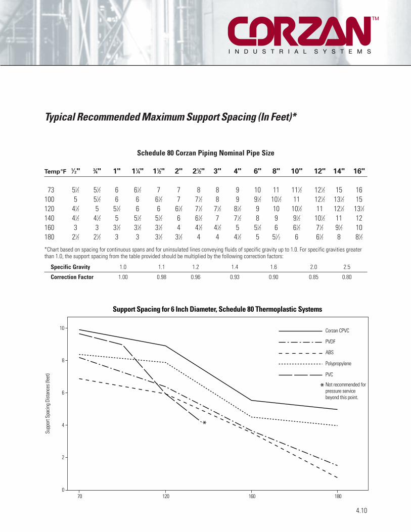
TM
Typical Recommended Maximum Support Spacing (In Feet)*
Schedule 80 Corzan Piping Nominal Pipe Size
Temp°F 1⁄2" 3⁄4" 1" 11⁄4" 11⁄2" 2" 21⁄2" 3" 4" 6" 8" 10" 12" 14" 16"
73 51⁄2 51⁄2 6 61⁄2 7 7 8 8 9 10 11 111⁄2 121⁄2 15 16100 5 51⁄2 6 6 61⁄2 7 71⁄2 8 9 91⁄2 101⁄2 11 121⁄2 131⁄2 15120 41⁄2 5 51⁄2 6 6 61⁄2 71⁄2 71⁄2 81⁄2 9 10 101⁄2 11 121⁄2 131⁄2140 41⁄2 41⁄2 5 51⁄2 51⁄2 6 61⁄2 7 71⁄2 8 9 91⁄2 101⁄2 11 12160 3 3 31⁄2 31⁄2 31⁄2 4 41⁄2 41⁄2 5 51⁄2 6 61⁄2 71⁄2 91⁄2 10180 21⁄2 21⁄2 3 3 31⁄2 31⁄2 4 4 41⁄2 5 51⁄2 6 61⁄2 8 81⁄2
*Chart based on spacing for continuous spans and for uninsulated lines conveying fluids of specific gravity up to 1.0. For specific gravities greaterthan 1.0, the support spacing from the table provided should be multiplied by the following correction factors:
Specific Gravity 1.0 1.1 1.2 1.4 1.6 2.0 2.5
Correction Factor 1.00 0.98 0.96 0.93 0.90 0.85 0.80
4.10
10
8
6
4
2
0
Supp
ort S
pacin
g Di
stan
ces (
feet
)
Support Spacing for 6 Inch Diameter, Schedule 80 Thermoplastic Systems
18016012070
Corzan CPVC
PVDF
ABS
Polypropylene
PVC
Not recommended forpressure servicebeyond this point.
*
*

TM
Typical Recommended Maximum Support Spacing (In Feet)*
4.11
Schedule 40 Corzan Piping Nominal Pipe Size
Temp°F 1⁄2" 3⁄4" 1" 11⁄4" 11⁄2" 2" 21⁄2" 3" 4" 6" 8" 10" 12" 14" 16"
60 5 51⁄2 6 6 61⁄2 61⁄2 71⁄2 8 81⁄2 91⁄2 91⁄2 10 101⁄2 12 1380 5 5 51⁄2 51⁄2 61⁄2 6 7 7 71⁄2 81⁄2 81⁄2 91⁄2 101⁄2 11 12
100 41⁄2 5 51⁄2 51⁄2 61⁄2 6 7 7 71⁄2 8 8 9 10 10 11120 41⁄2 41⁄2 5 51⁄2 51⁄2 51⁄2 61⁄2 7 7 71⁄2 71⁄2 8 9 9 91⁄2140 4 4 41⁄2 5 5 5 6 6 61⁄2 7 7 71⁄2 8 8 81⁄2180 21⁄2 21⁄2 21⁄2 3 3 3 31⁄2 31⁄2 4 41⁄2 5 51⁄2 6 61⁄4 7
*Chart based on spacing for continuous spans and for uninsulated lines conveying fluids of specific gravity up to 1.0. For specific gravities greaterthan 1.0, the support spacing from the table provided should be multiplied by the following correction factors:
Specific Gravity 1.0 1.1 1.2 1.4 1.6 2.0 2.5
Correction Factor 1.00 0.98 0.96 0.93 0.90 0.85 0.80
Source: Courtesy Piping Technology & Products, Inc., Houston, Texas
Pipe Hangers, Clamps, & Supports
Band Hanger Anchor StrapPipe Clamp Pipe Clamp Clevis Hanger
U-Bolt Roller Hanger
Roller HangerRoller Chair
Roller HangerRoller Hanger
Roller Stand

Corzan CPVC has a very low thermal conductivity value,approximately 1/300th that of steel. A prudent practice toensure worker safety is to insulate pipes which have exteriorsurface temperatures greater than 140°F. Because metal pipeshave such a high thermal conductivity, the exterior surfacetemperature is approximately equal to the temperature ofthe fluid being conveyed. Therefore, pipes carrying fluids attemperatures of 140°F or more should be insulated if thereis the possibility of worker contact. This generates morecost in the initial installation of a system and makes periodic inspections of the pipe more difficult. BecauseCPVC has a much lower thermal conductivity, the surfacetemperature of CPVC pipe is significantly lower than theinternal fluid temperature. Insulation is therefore often not
needed on Corzan pipe. The figure below shows the approximate pipe surface temperature as a function ofinternal fluid temperature for a piping system and with 73°Fair circulating at 0.75 feet per second. Corzan pipe sizes of2, 4, 6, 8, 10, and 12" Schedule 80 are represented. This figureis intended to demonstrate the significant difference betweensteel and CPVC pipe, but should not be used for systemdesign. The actual surface temperature of pipe in a workingsystem is dependent on many factors, including ambienttemperature, air circulation velocity and direction, etc.
CPVC’s low thermal conductivity also means that energyin the process stream is conserved. The rate of heat transferthrough CPVC piping is typically 50-60% that of steel piping.
4.12
Thermal Conductivity of Corzan CPVC
TM
180
170
160
150
140
130
120
110
100
Internal Temperature (°F)
Estim
ated
Pip
e Su
rface
Tem
pera
ture
(°F)
Estim
ated
Pip
e Su
rface
Tem
pera
ture
(°C)
Estimated Pipe Surface Temperature vs. Internal Fluid Temperature
180170 175155 160 165140 145 150
With 73°F (23°C) Air Circulating at 0.75 fps
40
45
50
55
60
65
70
75
80
Steel, all sizes
2" schedule 80 Corzan Pipe
12" schedule 80 Corzan Pipe

Proper installation of Corzan piping systems is critical to theperformance of the system. A few simple guidelines shouldbe followed to ensure long service life and safe operation.
HandlingProper care should be exercised when transporting orinstalling Corzan piping to prevent damage. Corzan pipingshould be stored and shipped only with other non-metallicpiping. It should not be dropped or dragged during handling,especially during extremely cold weather. The same treatmentshould apply to the handling of Corzan fittings.
Prior to actual installation, the pipe and fittings shouldbe thoroughly inspected for cracks, gouges, or other signsof damage. Particular attention should be given to theinside surface of the part. While the outside surface maynot exhibit damage, improper handling can result in damagethat appears only on the inside surface of the part.
CuttingLengths of pipe can be easily and successfully cut byfollowing a few simple guidelines. Best results are obtainedby using fine-toothed saw blades (16 to 18 teeth per inch)with little or no offset (0.025” max.). Circular power saws(6,000 rpm) or band saws (3,600 ft./min.) are recommendedusing ordinary hand pressure. Miter boxes or other guidedevices are strongly recommended for manual operation to ensure square cuts. Burrs, chips, and dust should beremoved following cutting to prevent contamination of thepiping system and facilitate joining.
Joining MethodsCorzan piping can be installed using a number of joiningtechniques. Solvent welding, flanging, and threading arethe more common methods and are covered in greaterdetail in this section. Back welding of joints using hot gaswelders is also covered in some detail. Less common joiningmethods are also possible with Corzan piping and fittings,including butt fusion and Victaulic techniques. ContactNoveon or the Corzan piping manufacturers for assistancewith less common joining methods.
Hanging/Laying of PipeCorzan piping can be installed above ground or buriedunderground. Methods to minimize stress on the piping as aresult of installation are covered in detail below.
System StressAny metal or non-metal piping system is subject to stress-induced corrosion. As a result, special attentionshould be given to minimizing stress throughout the system.The total stress on a piping system includes not only theknown pressure stress, but also stresses from sources suchas expansion or installation. Expansion stresses can be minimized with expansion joints or loops. Installationalstresses are minimized with careful installation techniques.Pipe and fittings should be properly prepared when jointsare made up. Hangers and supports should be properlyspaced to prevent sagging and should not cut into the pipeor clamp it tightly, preventing movement. System componentsshould not be forced into place.
Thermal ExpansionCorzan piping has the lowest coefficient of thermal expansionof any thermoplastic piping. However, thermal expansion willbe greater than that of metal piping. Typically, expansionloops or offsets in the piping are designed to account forany thermal expansion. These design methods are coveredin detail in Section 4.8. Expansion joints can also beinstalled. Information on expansion joints can be obtained bycontacting Noveon or Corzan piping manufacturers.
Testing the Piping SystemAfter the piping system is installed and any solvent cementis fully cured, the system should be pressure tested andchecked for leaks using water. Testing using compressed airor inert gas is not recommended. All entrapped air shouldbe allowed to vent as the system is filled with water. Waterfilling should occur at a velocity not more than 1ft/sec.After filling, the system should be pressured to 125% of themaximum design pressure of the lowest rated part of thesystem. Pressure should be held for no more than one hourwhile the system is checked for leaks.
4.13
General Installation Guidelines
TM

CuttingCorzan pipe can be easily cut with a ratchet cutter, wheel-type plastic tubing cutter, power saw, or fine-toothedsaw. To ensure the pipe is cut square, a mitre box must beused when cutting with a saw. Cutting the pipe as squarelyas possible provides the maximum bonding surface area.
Chamfering and DeburringBurrs and filings can prevent proper contact between thepipe and fitting and may put undue stress on the pipe andfitting assembly. Burrs and filings must be removed fromthe outside and inside of the pipe. A chamfering tool or fileis suitable for this purpose. A slight bevel should be placedat the end of the pipe to ease entry of the pipe into thesocket and minimize the chances of wiping solvent cementfrom the fitting. For pipe sizes 2 inches and larger a 10°-15°chamfer of 3/32" is recommended.
Fitting PreparationLoose soil and moisture should be wiped from the fittingsocket and pipe end with a clean, dry rag. Moisture canslow the curing, and at this stage of assembly excessivewater can reduce the joint strength. The dry fit of the pipeand fitting should be checked. The pipe should enter thefitting socket easily 1/3 to 2/3 of the depth. If the pipebottoms in the fitting with little interference, extra solventcement should be used to prepare the joint.
Primer ApplicationPrimer is needed to prepare the bonding area for theaddition of the cement and subsequent assembly. It isimportant that a proper applicator be used. A dauber, swabor paintbrush approximately half the size of the pipe diameteris appropriate. A rag should not be used. Primer is applied toboth the outside of the pipe end and inside of the fittingsocket, redipping the applicator as necessary to ensure thatthe entire surface of both is tacky.
Solvent Cement ApplicationSolvent cement must be applied when the pipe surface istacky, not wet, from primer. Joining surfaces must bepenetrated and softened. Cement should be applied with a natural bristle brush or swab half the size of the pipediameter. A dauber may be used to apply cement on pipesizes below 2 inches. A heavy, even coat of cement shouldbe applied to the outside of the pipe end, and a mediumcoat should be applied to the inside of the fitting socket.Pipe sizes greater than 2 inches should receive a secondcoat of cement on the pipe end.
AssemblyAfter cement application, the pipe should immediately beinserted into the fitting socket and rotated 1/8 to 1/4 turnuntil the fitting-stop is reached. The fitting should beproperly aligned for installation at this time. The pipe mustmeet the bottom of the fitting socket. The assembly shouldbe held in place for 10 to 30 seconds to ensure initialbonding and to avoid pushout. A bead of cement should beevident around the pipe and fitting juncture. If this bead isnot continuous around the socket shoulder, it may indicatethat insufficient cement was applied. In this case, thefitting should be discarded and the joint reassembled.Cement in excess of the bead may be wiped off with a rag.
Set and Cure TimesSolvent cement set and cure times are a function of pipesize, temperature, relative humidity, and tightness of fit.Drying time is faster for drier environments, smaller pipesizes, high temperatures, and tighter fits. The assemblymust be allowed to set, without any stress on the joint, for 1 to 5 minutes depending on the factors just discussed.Following the initial set period, the assembly can be handledcarefully avoiding significant stresses to the joint. Refer tothe following table for minimum cure times prior to testing.
Extra care should be exercised when systems areassembled in extreme temperature conditions. Extra set and cure times should be allowed when the temperature isbelow 40°F (4°C). When the temperature is above 100°F(38°C), the assembler should ensure that both surfaces tobe joined are still wet with cement before joining them.
4.14
Joining Corzan Pipe and Fittings – Solvent Cementing
TM

Recommended Set TimesAfter a joint is assembled using solvent cement, it shouldnot be disturbed for a period of time to allow for proper“setting” of the newly prepared joint. Recommended settimes are as follows:
Ambient to 11⁄2” 4” to 10” toTemperature 11⁄4” to 3” 8” 12”
60° to 110°F 15 min 30 min 1 hr 2 hr40° to 60°F 1 hr 2 hr 4 hr 8 hr0° to 40°F 3 hr 6 hr 12 hr 24 hr
Recommended Cure TimesAfter a joint is assembled using solvent cement, the cementmust be allowed to properly “cure” before the piping systemis pressurized. Recommended minimum cure times areshown below. These recommendations should only serve asa guide since atmospheric conditions during installation willaffect the curing process.
High humidity and/or colder weather will require longercure times: typically add 50% to the recommended curetime if surroundings are humid or damp.
4.15
Joining Corzan Pipe and Fittings – Solvent Cementing (cont.)
TM
CURE TIME FOR OPERATING/TEST PRESSURES TO 180 PSIG
Ambient to 11⁄2” 4” to 10” toTemperature 11⁄4” to 3” 8” 12”
60° to 110°F 1 hr 2 hr 6 hr 24 hr40° to 60°F 2 hr 4 hr 12 hr 40 hr0° to 40°F 8 hr 16 hr 48 hr 8 days
CURE TIME FOR OPERATING/TEST PRESSURES ABOVE 180 PSIG**
Ambient to 11⁄2” 4” to 10” toTemperature 11⁄4” to 3” 8” 12”
60° to 110°F 6 hr 6 hr 24 hr 24 hr40° to 60°F 12 hr 24 hr 48 hr 40 hr0° to 40°F 48 hr 96 hr 8 days 8 days**DO NOT exceed maximum working pressure of piping for given pipe size andoperating temperature
Corzan Schedule 80 pipe up to and including 4” in diameter,and which will operate at 130°F or less, may be threaded.The threads should be in accordance with ANSI B1.20.1Taper Pipe Thread. Threaded joints are derated to 50% ofthe pressure rating of the Schedule 80 pipe at the operatingtemperature. Schedule 40 pipe, Schedule 80 pipe largerthan 4," or piping for systems which will operate at atemperature greater than 130°F should not be threaded.Flanges, unions, or Victaulic couplings may be used whereoccasional disassembly is required.
Pipe to be threaded should be squarely cut with a handsaw or power saw. A mitre box should be used when pipe is cut by hand. A fine-toothed blade (16-18 teeth per inch)works best for cutting plastics. Burrs should be removedfrom the cut end of the pipe with a knife or similar tool. A slight chamfer on the pipe end will speed threading. Atapered plug should be inserted into the pipe before threadingto provide additional support and prevent distortion of thepipe or threads. The pipe should be held in a pipe vise, butsaw-toothed jaws should not be used. A rubber sheet orsome other type of material may be used to protect the pipefrom the rough edges of the pipe vise.
The dies used for cutting threads on Corzan pipe shouldbe clean, sharp, and in good condition. They should bereserved for use only on plastic materials. Pipe threadingdies should have a 5° negative front rake when powerthreading machines are used, and a 5°-10° negative frontrake when pipes are threaded by hand. When powerthreading equipment is used, the dies should not be drivenat high speeds or with heavy pressure. Soap and watersolutions or water soluble machine oils are suitable cuttinglubricants for Corzan pipe.
The threads may be checked with a ring gauge toensure accuracy. The gauging tolerance is +/- 11⁄2 turns.
Threaded parts must be prepared for assembly bybrushing away cutting debris from the threads. Degreasingsolvents should never be used to clean CPVC threads.
Teflon tape is the recommended thread sealant forCorzan threaded parts. Many Teflon paste thread sealantsare also suitable, although some contain components whichmay contribute to cracking of the pipe or fitting. The supplierof the paste should be consulted to determine its compatibilitywith Corzan CPVC. Solvent cement should never be appliedto threaded joints.
After the thread tape has been applied, the threadedfitting may be screwed onto the pipe and tightened handtight. If desired, a strap wrench may be used to tighten thejoint an additional turn. Overtightening of threaded plasticjoints will weaken the joint. When Corzan pipe or fittingsare connected to metal with a threaded joint, the Corzan pipeor fittings should have male threads, and the metal shouldhave female threads.
4.16
Threading of Corzan Schedule 80 Pipe
TM

TM
Flanging of Corzan Pipe
Flanging can be used to provide temporary disassembly of apiping system or when it is not possible to make up solventcemented joints at the assembly site.
Flanges are joined to the pipe by solvent cement orthreaded joints. Refer to the sections on solvent cementingor threading of Corzan pipe for the proper techniques.
Flanged joints incorporate an elastomeric gasketbetween the mating faces to provide for a seal. The gasketselected must be full-faced and have a hardness of 55-80durometer A. Typically, gaskets are 1/8” thick. The gasketmaterial must be resistant to the chemical environment.Many manufacturers of gasketing materials supply this kindof information. If the piping system is for potable water service, the gasket must also be approved for potable water.
The flanges should be carefully aligned and the boltsinserted through matching holes. A flat washer should beused beneath each nut and bolt head. Each bolt should bepartially tightened in the alternating sequence indicated inthe patterns below. A torque wrench should be used for thefinal tightening of the bolts. The bolts should be tightenedto the torque recommended in the table below in the samealternating sequence used previously.
Flange joints are typically rated to 150 psi at 73°F. For systems operating at higher temperatures, the flangepressure rating should be derated per the manufacturer’srecommendations.
RECOMMENDED BOLT TORQUE*
Nominal Number of Bolt Recommended
Pipe Size Bolt Holes Diameter (in) Torque (ft-lbs)
1⁄2 - 11⁄2 4 1/2 10-152 - 3 4 5/8 20-30
4 8 5/8 20-306 8 3/4 33-508 8 3/4 33-50
10 12 7/8 53-7512 12 1 80-110’
*Information given as guidelines only. Consult the manufacturer’sliterature for flange requirements.
4.17
1
1
1
2
333 4 4 4
5
5
6
6
77
8 89
10
11
12
2
2
Flange Bolt Tightening Patterns
4-Bolt Flange8-Bolt Flange
12-Bolt Flange

Back-welding may be used to repair minor leaks in solventcemented or threaded joints. Back-welding is a hot-airwelding technique which consists of forcing a welding rod to fuse in the joint fillet while both rod and fillet aresoftened with hot air.
Before hot-air welding begins, the section of pipingwhere the repair will be made must be emptied. Jointsshould not be welded with fluid still in the pipe.
All dirt and moisture should be wiped away from thejoint to be repaired. Excess dried solvent cement around thejoint should be removed with an emery cloth. Residualsolvent cement may tend to scorch and burn during welding.If the joint to be welded is a threaded joint, excess threads inthe joint area should be removed with a file in order toprovide a smooth surface for welding.
If a speed tip will be used for back-welding, refer to thismanual’s section on fabrication with high speed hot airwelding for the proper conditions and techniques to use.
If welding will be done by feeding the rod manually, thefollowing conditions and procedures should be used:
The welding temperature should be approximately 550-600°F. Only welding rod made of Corzan CPVC shouldbe used for back welding CPVC joints.
The end of the welding rod should be inserted into thejunction of the pipe and fitting, and the rod should be heldat a 90° angle to the joint. The rod and base materialshould be preheated with the welding torch 1/4 to 3/4 inchaway from both the rod and the base material and fanningback and forth in the immediate welding area. While preheating, the rod can be moved up and down until it issoft enough to stick to the base.
When the materials are softened enough to fuse, the rodshould be advanced by the application of a slight pressure.The fanning motion of the torch should be continuedthroughout the welding process. When the weld is finished,another inch of rod material should be lapped over the bead.
When large diameter pipe is welded, three beads maybe required to fill the joint adequately. The first bead shouldbe laid directly into the joint fillet, and the subsequent beadson either side of the first bead.
4.18
Back-Welding of Pipe Joints
TM

ReferencesThese guidelines are based upon the following:1. ASTM D2774: Standard Recommended Practice forUnderground Installation of Thermoplastic Piping2. Piping Manufacturer’s Installation Instructions3. Industry Experience
For additional information and data, consult ASTMstandards D2774, D2321, or F645.
Installation ProceduresThis procedure will cover the typical steps encountered inunderground installations: trench design, trench preparation,piping assembly, laying of pipe, and backfilling.
Trench DesignWidth: The trench should be of adequate width to allow
for convenient installation, but as narrow aspossible depending on whether the piping willbe assembled inside or outside of the trench.
Depth: The trench depth should be sufficient to placethe pipe deep enough to meet frost, above-groundload, and any trench bedding requirements.
Frost: Piping at least 12 inches below the frost line. Loads: Piping should be deep enough to keep external
stress levels below acceptable design stress.Design stress will be determined by pipe sizeand operating temperature and may be governedby various codes.
Bedding: 4 to 6 inches underneath piping, if necessary(see below)
Trench PreparationThe trench bottom should be continuous, relatively smoothand free of rocks. If ledge rock, hardpan, boulders, or rocksthat are impractical to remove are encountered, it will benecessary to pad the trench bottom to protect the pipingfrom damage. 4 to 6 inches of tamped earth or sand beddingwill be sufficient in such situations.
Piping Assembly/PlacementPiping may be assembled using conventional solventcementing techniques either inside or outside of the trenchdepending on the specific installation requirements.Solvent cement usually requires at least 12 to 24 hours forthe cemented joint to cure properly. During this critical curingprocess, every effort should be made to minimize the stresson any joints. As a result, the piping should not be movedduring the curing period, nor should the pipe be backfilled,or otherwise constrained during curing. See the recommen-dations on joint curing time to determine the exact curingrequirements for a specific installation.
If the piping was assembled outside of the trench, thepipe may be placed into the trench after proper curing, butMUST NOT be rolled or dropped into place. Long lengthsof joined piping should be properly supported as the pipingis put into place to prevent excessive stress.
After proper curing and before backfilling, the pipingshould be brought to within 15°F of the expected operatingtemperature. Backfilling can proceed while the piping ismaintained at this temperature in order to minimize stresson the system due to thermal expansion/contraction. If thisstep is impractical, then stress calculations must be done todetermine the loads that will be created due to constrainedthermal expansion/contraction.* These loads must then becompared to the design stress of the particular piping system.
*Refer to page 4.9 for the calculation for the stress developedwhen thermal expansion is constrained.
4.19
Underground Installation Guidelines
TM

BackfillingBackfilling should only proceed after all solvent cementjoints have been properly cured and the piping broughtclose to normal operating temperature, if operation will be more than 15°F different than the current ambient temperature. The piping should be uniformly supported overits entire length on firm, stable material.
Backfill material should be free of rocks and have aparticle size no greater than 1/2.” Piping should initially besurrounded with backfill to provide between 6” and 8” ofcover. The backfill should be compacted using vibratory or
water flooding methods. If water flooding is used, additionalmaterial should not be added until the water flooded backfillis firm enough to walk on. Backfill containing a significantamount of fine-grained material, such as silt or clay, shouldbe hand or mechanically tamped.
The remainder of the backfill should be placed andspread in approximately uniform layers to completely fill the trench without voids. Particle size for this final fillshould not exceed 3." Rolling equipment or heavy tampersshould only be used to consolidate the final backfill.
4.20
Underground Installation Guidelines (cont.)
TM

With increasing regulation of air emissions, the need forreliable fume handling systems, especially in corrosive environments, is growing rapidly. To meet this demandCorzan Industrial Systems offer the same outstanding balanceof properties in round duct, fabricated duct fittings, industrialsheet, and welding rod. As a result, these properties can bedesigned and fabricated into entire fume handling systems.
Round duct and fittings are available in sizes up to 24." For larger size systems, Corzan industrial sheet can be fabricated into square or round duct using techniquesdescribed in greater detail in the fabrication section of thismanual. Corzan ducting systems can also be connected withfume scrubbers or other emission control equipment made of Corzan CPVC to ensure excellent corrosion resistancethroughout the entire system.
5.1
Corzan Ducting Systems
TM
Property Test Condition English Units SI Units
GENERAL
Specific Gravity ASTM D792 73°F/23°C 1.55Specific Volume 73°F/23°C .0103 ft3/lb 0.645 cm3/gWater Absorption ASTM D570 73°F/23°C +0.03% +0.03%
212°F/100°C +0.55% +0.55%Rockwell Hardness ASTM D785 73°F/23°C 119Cell class ASTM D1784 23437
MECHANICAL
*Notched Izod Impact ASTM D256 73°F/23°C 1.5 ft lbf /in 80 J/m*Tensile Strength ASTM D638 73°F/23°C 8000 psi 55 N/mm2
*Tensile Modulus ASTM D638 73°F/23°C 360,000 psi 2500 N/mm2
*Flexural Strength ASTM D790 73°F/23°C 15,100 psi 104 N/mm2
*Flexural Modulus ASTM D790 73°F/23°C 415,000 psi 2860 N/mm2
Compressive Strength ASTM D695 73°F/23°C 10,100 psi 70 N/mm2
Compressive Modulus ASTM D695 73°F/23°C 196,000 psi 1350 N/mm2
THERMAL
Coefficient of ASTM D696 3.9x10⁻⁵ in/in/°F 2.2x10⁻⁵ m/m/KThermal Expansion
Thermal Conductivity ASTM C177 0.95 BTU in/hr/ft2/°F 0.066 Wm/K/m2
Heat Distortion Temperature ASTM D648 217°F 103°C*Heat Capacity (Specific Heat) DSC 73°F/23°C 0.21 BTU/lbm°F 0.90 J/gK
212°F/100°C 0.26 BTU/lbm°F 1.10 J/gK
FLAMMABILITY
Flammability Rating UL 94 0.062 in/0.157 cm V-O, 5VB, 5VAFlame Spread ASTM E84 15Smoke Developed ASTM E84 300Limiting Oxygen Index ASTM D2863 60%Burning Rate (in/mm) Self extinguishing
ELECTRICAL
Dielectric Strength ASTM D147 1250 V/mil 492,000 V/cmDielectric Constant ASTM D150 60 Hz, 30°F/-1°C 3.70 3.70Power Factor ASTM D150 1000 Hz 0.007% 0.007%Volume Resistivity ASTM D257 73°F/23°C 3.4x10¹⁵ ohm/cm 3.4x10¹⁵ ohm/cm
*Plots of these properties versus temperature follow this table.

TM
5.2
Basic Physical Properties
10,000
8,000
6,000
4,000
2,000
0
6560555045403530252015105
20 30 40 50 60 70 80 90
50 75 100 125 150 175 200
Temperature (°C)
Temperature (°F)
Tens
ile S
treng
th (p
si)
Tens
ile S
treng
th (N
/mm
2 )
Tensile Strength
0
50,000
100,000
150,000
200,000
250,000
300,000
350,000
400,000
500
1,000
1,500
2,000
2,500
20 30 40 50 60 70 80 90
50 75 100 125 150 175 200
Temperature (°C)
Temperature (°F)
Tens
ile M
odul
us (p
si)
Tens
ile M
odul
us (N
/mm
2 )Tensile Modulus

TM
5.3
Basic Physical Properties (cont.)
16,000
14,000
12,000
10,000
8,000
6,000
4,000
2,000
0
100
90
80
70
60
50
40
30
20
10
20 30 40 50 60 70 80 90
50 75 100 125 150 175 200
Temperature (°C)
Temperature (°F)
Flexu
ral S
treng
th (p
si)
Flexu
ral S
treng
th (N
/mm
2 )
Flexural Strength
0
50,000
100,000
150,000
200,000
250,000
300,000
350,000
450,000
400,000
500
1,000
1,500
2,000
3,000
2,500
20 30 40 50 60 70 80 90
50 75 100 125 150 175 200
Temperature (°C)
Temperature (°F)
Flexu
ral M
odul
us (p
si)
Flexu
ral M
odul
us (N
/mm
2 )Flexural Modulus

TM
5.4
Basic Physical Properties (cont.)
12,000
10,000
8,000
6,000
4,000
2,000
0
60
70
80
50
40
30
20
10
20 30 40 50 60 70 80 90
50 75 100 125 150 175 200
Temperature (°C)
Temperature (°F)
Com
pres
sive
Stre
ngth
(psi)
Com
pres
sive
Stre
ngth
(N/m
m2 )
Compressive Strength
0
25,000
100,000
75,000
50,000
125,000
150,000
175,000
200,000
225,000
250,000
200
400
600
800
1,000
1,200
1,400
1,600
20 30 40 50 60 70 80 90
50 75 100 125 150 175 200
Temperature (°C)
Temperature (°F)
Com
pres
sive
Mod
ulus
(psi)
Com
pres
sive
Mod
ulus
(N/m
m2 )
Compressive Modulus

TM
5.5
0.660.68
0.720.70
0.740.760.780.800.820.840.860.880.90
8759009259509751,0001,0251,0501,0751,100
1,150403020 50 60 70 80 90 100
70 9080 120110 140 160 170 190 200
Spec
ific H
eat
(BTU
/lbm
° F)
Spec
ific H
eat
(J/k
g °K
)
850
1,125
100 130 150 180 210
Temperature (°C)Specific Heat
Temperature (°F)
Basic Physical Properties (cont.)
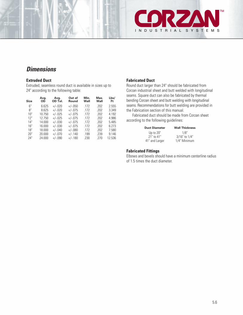
Extruded DuctExtruded, seamless round duct is available in sizes up to24" according to the following table:
Avg. Avg. Out of Min. Max. Lbs/Size OD OD Tol. Round Wall Wall Ft
6" 6.625 +/-.020 +/-.050 .172 .202 2.5558" 8.625 +/-.020 +/-.075 .172 .202 3.34910" 10.750 +/-.025 +/-.075 .172 .202 4.19212" 12.750 +/-.025 +/-.075 .172 .202 4.98614" 14.000 +/-.030 +/-.075 .172 .202 5.48516" 16.000 +/-.030 +/-.075 .172 .202 6.27318" 18.000 +/-.040 +/-.080 .172 .202 7.58020" 20.000 +/-.070 +/-.140 .199 .239 9.14624" 24.000 +/-.090 +/-.180 .230 .270 12.536
Fabricated DuctRound duct larger than 24" should be fabricated fromCorzan industrial sheet and butt welded with longitudinalseams. Square duct can also be fabricated by thermal bending Corzan sheet and butt welding with longitudinalseams. Recommendations for butt welding are provided inthe Fabrication section of this manual.
Fabricated duct should be made from Corzan sheetaccording to the following guidelines:
Duct Diameter Wall Thickness
Up to 20" 1/8"21" to 41" 3/16" to 1/4"
41" and Larger 1/4" Minimum
Fabricated FittingsElbows and bevels should have a minimum centerline radiusof 1.5 times the duct diameter.
5.6
Dimensions
TM

The excellent mechanical properties of Corzan CPVC enableCorzan fume handling systems to withstand higher vacuumloadings and differential pressure conditions compared to traditional materials, especially at elevated temperatures.Testing of CPVC duct by Noveon indicates that Corzan duct will perform well in most conditions encountered in a typicalfume handling application.
Negative PressureCorzan CPVC Duct performs well when exposed to harsh environments. This was demonstrated by testing conducted at an independent test facility to determine critical collapsepressures. Corzan CPVC Duct was taken to extremes undervarious negative pressure conditions to validate the product’sstructural integrity at elevated temperatures when exposed to severe conditions. The negative pressure ratings shown inTable 1 are based on actual testing of round seamlessextruded CPVC Duct at various temperatures and incorporatea 1.5:1 safety factor.
Positive PressureCorzan CPVC Duct can endure greater levels of positive internal pressure than negative internal pressure. Table 2 shows the maximum recommended internal pressure rating inPSI for Corzan CPVC round seamless extruded Duct at variousroom temperatures.
5.7
Product Ratings and Capability
TM
TABLE 1
MAX. INTERNAL NEGATIVE PRESSURE RATING
INCHES OF WATER @ VARIOUS TEMPERATURES ˚F
Size Temperature ˚F
73 100 120 140 160 180 200
6” 426 371 316 263 208 153 988” 193 168 143 118 93 70 4510” 100 86 73 60 48 35 2312” 60 51 43 36 28 20 1314” 45 38 33 26 21 15 1016” 30 26 21 18 13 10 618” 26 23 20 16 13 10 620” 28 25 21 16 13 10 624” 20 18 15 13 10 6 3
PSI=Inches of Water x .0361: Inches of Mercury=Inches of Water x .07355
TABLE 2
MAX. INTERNAL POSITIVE PRESSURE RATING
PSI @ VARIOUS TEMPERATURES ˚F
Size Temperature ˚F
73 100 120 140 160 180 200
6” 70 56 45 35 26 16 138” 53 43 33 26 20 13 1010” 43 35 28 21 16 10 812” 36 30 23 18 15 8 614” 33 26 21 16 13 8 616” 28 23 18 13 11 6 518” 25 20 15 11 10 5 520” 26 21 16 13 10 6 524” 25 20 15 11 10 5 5
NOTE: Maximum values stated are for extruded duct pipe only, and incorporate a 1.5:1 safety factor. Consideration should be given to system design, method of fabrication, andjoining which may require additional system derating. The use of compressed air or gasesis not recommended for use with Corzan PVC/CPVC Duct piping.

Joining MethodsCorzan CPVC Duct can be easily assembled in the fieldusing standard thermoplastic-pipe joining techniques. Themost common methods involve thermal hot-air welding orthe solvent-cementing process. Both of these methodsprovide reliable, cost-effective joints. Other methods ofjoining and fabricating Corzan CPVC Duct and systemaccessories include thermoforming, extrusion welding, andhot-plate welding.
Solvent CementingBelled-end duct, couplings, flanges and other socket-stylefittings can be joined using the solvent-cementing process.This process involves the application of a primer andsolvent cement to join system components. This joiningmethod has been used successfully for over 30 years intough corrosive pressure applications. When properlyconducted, this method provides a strong, homogenousjoining area in which the mating surfaces are chemicallyfused together, producing a strong, leak-tight seal whencured. Detailed solvent-cementing procedures are availableand should be referenced for proper installation techniques.Adequate surface-to-surface contact of the parts beingjoined is necessary for reliable solvent-cemented joints.Generally, a minimum socket depth of 3" (all sizes) willprovide sufficient joint strength for most systems. Sinceduct dimensional tolerances can appreciable whencompared to heavy wall pipe, the use of extra-heavy-bodiedCPVC cement (such as IPS 3461 or equivalent) isrecommended due to the cement’s excellent gap-fillingproperties. Care should be used when solvent-cementingduct diameters 18" and larger to ensure tightness of fit ofmatting components. The solvent-cementing method is notrecommended for any type of end-joining.
Thermal WeldingThe hot-air welding technique utilizes clean hot air to preheat the duct material and CPVC welding rod, whilepressure is applied to the weld area as the rod is guided.This joining method results in the surface molecules of theparts being joined to fuse together at the weld seam. Onlywelding rod produced from Corzan CPVC material isrecommended for this joining process to ensure the highestsystem integrity. All welding should be conducted bypersonnel adequately trained in the art of hot-air weldingthermoplastics. Detailed information concerning CorzanCPVC welding and fabrication is available.
Flanged SystemsFor flanged systems, the general recommendations forflange fabrication are as follows:
Flange Thickness 3/16" to 1/4"Flange Width 11⁄4" to 2"
Distance Between Bolt Holes 3" to 4"Bolt Hole Diameter 5/16" to 3/8"
Bolts 1/4" to 5/16"
5.8
Installation of Corzan Ducting Systems
TM

Corzan CPVC Duct requires fewer supports at elevatedtemperatures than other thermoplastic duct systems due toits exceptional heat resistance, a significant cost-savingsadvantage. Proper support spacing is dependent on the ductdiameter, the temperature parameters of the system, thelocation of concentrated stress loads, and the possibility ofprocess solids accumulation within the system. As with allpiping systems, proper support spacing is critical to ensurethat the deflection and sagging are kept to a minimum. Thisprevents unnecessary stress on the system, and reduces thepossibility of creating fluid condensation/collection areas.Drains must be installed where accumulation of moisture isexpected and at low points in the system; these locationsshall be specified on the drawings. The values stated inTable 1 are based on actual testing of air-filled duct atvarious temperatures, and incorporate a reasonable safetyfactor. Depending on the type of system service,consideration must be given to the possibility of solidsaccumulation within the line, particularly where twoseparate process lines intersect. (Solids can be createdwithin a system as the result of a chemical reaction of thefumes being extracted.) Stress loads can be generated bythe additional weight of accumulated solids, and this factshould be addressed with adequate system support where required. Proper system inspection, cleaning andmaintenance should be enforced to prevent the formation of additional weight loads. Refer to Table 1 for maximumsupport spacing of horizontal air-filled duct at varioustemperatures.
TABLE 1MAXIMUM HANGER SUPPORT SPACING IN FEET
Size Temperature °F
73 100 120 140 160 180 200
6" 10 10 10 10 10 8 88" 10 10 10 10 10 8 810" 10 10 10 10 10 10 1012" 10 10 10 10 10 10 1014" 12 12 12 12 10 10 1016" 12 12 12 12 12 10 1018" 12 12 12 12 12 12 1220" 12 12 12 12 12 12 1224" 12 12 12 12 12 12 12
As with any system, Corzan CPVC Duct must beindependently supported at fans, flexible connections,hoods, scrubbers, tanks, and other system components toensure the highest system integrity. In the case whereflexible connections are installed as expansion joints, asuitable support or hanger shall be provided at each end ofthe flexible connection. Other heavy system componentssuch as dampers, filters, etc. must also be independentlysupported to prevent high stress concentration areas.Hangers and supports shall be securely fastened to thebuilding structure to avoid vibration, and should be installedin such a manner as to prevent conditions of stress on thesystem (properly aligned). Seismic design and constructionpractices for hangers and supports shall be followed whereapplicable.
Hangers selected shall have an adequate load-bearingsurface free of rough or sharp edges, and shall not causedamage to the duct during use. The hangers and hangerhardware shall be of a corrosive-resistant material suitablefor use in the system environment. Hangers are to be of atype that will not restrict linear movement of the systemdue to expansion and contraction. Overtightening must beavoided to prevent duct deformation and restriction ofmovement.
ReinforcementDue to Corzan CPVC Duct’s inherent rigidity and heatresistance, additional system reinforcements or flanges are not required for 6" through 24" sizes up to 160°F and10" of negative internal static pressure, provided propersupport spacing requirements are followed. Additionalreinforcements are not required for systems under positive pressure.
5.9
Hangers and Supports
TM

Thermal Expansion and ContractionThe coefficient of linear expansion (y) for Corzan CPVC Ductis 3.9 x 10⁻⁵ in/in/°F, the lowest thermal expansion rate ofcommonly used thermoplastics. As with all piping products,thermal expansion and contraction of the system must beconsidered and properly addressed during the design andinstallation of the system. The expansion or contraction rateof Corzan CPVC Duct can be calculated as follows:
�L = LdC�Twhere: �L = expansion or contraction of duct in inches
Ld = Length of duct run in feetC = 3.9 x 10⁻⁵ in/in/°F
(coefficient of thermal expansion)�T = Temperature change °F (T max. - T in.)
T max. = maximum change in operating temperature (°F)T in. = temperature at time of installation (°F)
The most common means to compensate for changes inlength is with the installation of in-line expansion joints,either flexible sleeve type or o-ring piston type being themost common. The effects of thermal expansion andcontraction can also be compensated by using the inherentline flexibility of the system to construct expansion loopsand offsets where required. Additional detailed informationconcerning the effects and control of thermal expansion andcontraction, and other information pertaining to the designand installation of CPVC piping products, is available fromNoveon, Inc.
5.10
Hangers and Supports (cont.)
TM

The superior corrosion resistance and high temperatureperformance of Corzan CPVC is available in 48” x 96” sheet.The excellent fire performance of Corzan CPVC will also beuseful in many sheet applications. Sheet products areavailable in thicknesses ranging from 1/8” to 3,.” and areeither extruded or compression molded.
The ability to bend, shape, and weld sheet made fromCorzan CPVC enables its use in a wide variety of processapplications including tanks, scrubbers, and ventilationsystems.
Recommendations for fabricating equipment usingsheet are covered in the Fabrication section of the designmanual. Sheet made from Corzan CPVC can readily be overwrapped with Fiber Reinforced Polyester (FRP), if necessary, and will not require fabric-backing to achieveproper adhesion between the CPVC and FRP.
Refer to the Product Availability section of the designmanual for information on where to obtain sheet made from Corzan CPVC.
6.1
Industrial Sheet/Lining
TM
Property Test Condition English Units SI Units
GENERAL
Specific Gravity ASTM D792 73°F/23°C 1.55Specific Volume 73°F/23°C .0103 ft3/lb 0.645 cm3/gWater Absorption ASTM D570 73°F/23°C +0.03% +0.03%
212°F/100°C +0.55% +0.55%Rockwell Hardness ASTM D785 73°F/23°C 119Cell class ASTM D1784 23447
MECHANICAL
*Notched Izod Impact ASTM D256 73°F/23°C 1.5 ft lbf /in 80 J/m*Tensile Strength ASTM D638 73°F/23°C 8000 psi 55 N/mm2
*Tensile Modulus ASTM D638 73°F/23°C 360,000 psi 2500 N/mm2
*Flexural Strength ASTM D790 73°F/23°C 15,100 psi 104 N/mm2
*Flexural Modulus ASTM D790 73°F/23°C 415,000 psi 2860 N/mm2
Compressive Strength ASTM D695 73°F/23°C 10,100 psi 70 N/mm2
Compressive Modulus ASTM D695 73°F/23°C 196,000 psi 1350 N/mm2
THERMAL
Coefficient of ASTM D696 3.4x10⁻⁵ in/in/°F 1.9x10⁻⁵ m/m/KThermal Expansion
Thermal Conductivity ASTM C177 0.95 BTU in/hr/ft2/°F 0.066 Wm/K/m2
Heat Distortion Temperature ASTM D648 217°F 103°C*Heat Capacity (Specific Heat) DSC 73°F/23°C 0.21 BTU/lbm °F 0.90 J/gK
212°F/100°C 0.26 BTU/lbm °F 1.10 J/gK
FLAMMABILITY
Flammability Rating UL 94 0.062 in/0.157 cm V-O, 5VB, 5VAFlame Spread ASTM E84 15Smoke Developed ASTM E84 70-125Limiting Oxygen Index ASTM D2863 60%
ELECTRICAL
Dielectric Strength ASTM D147 1250 V/mil 492,000 V/cmDielectric Constant ASTM D150 60 Hz, 30°F/-1°C 3.70 3.70Power Factor ASTM D150 1000 Hz 0.007% 0.007%Volume Resistivity ASTM D257 73°F/23°C 3.4x10¹⁵ ohm/cm 3.4x10¹⁵ ohm/cm
*Plots of these properties versus temperature follow this table.

TM
6.2
Basic Physical Properties
10,000
8,000
6,000
4,000
2,000
0
6560555045403530252015105
20 30 40 50 60 70 80 90
50 75 100 125 150 175 200
Temperature (°C)
Temperature (°F)
Tens
ile S
treng
th (p
si)
Tens
ile S
treng
th (N
/mm
2 )
Tensile Strength
0
50,000
100,000
150,000
200,000
250,000
300,000
350,000
400,000
500
1,000
1,500
2,000
2,500
20 30 40 50 60 70 80 90
50 75 100 125 150 175 200
Temperature (°C)
Temperature (°F)
Tens
ile M
odul
us (p
si)
Tens
ile M
odul
us (N
/mm
2 )Tensile Modulus

TM
6.3
Basic Physical Properties (cont.)
16,000
14,000
12,000
10,000
8,000
6,000
4,000
2,000
0
100
90
80
70
60
50
40
30
20
10
20 30 40 50 60 70 80 90
50 75 100 125 150 175 200
Temperature (°C)
Temperature (°F)
Flexu
ral S
treng
th (p
si)
Flexu
ral S
treng
th (N
/mm
2 )
Flexural Strength
0
50,000
100,000
150,000
200,000
250,000
300,000
350,000
450,000
400,000
500
1,000
1,500
2,000
3,000
2,500
20 30 40 50 60 70 80 90
50 75 100 125 150 175 200
Temperature (°C)
Temperature (°F)
Flexu
ral M
odul
us (p
si)
Flexu
ral M
odul
us (N
/mm
2 )Flexural Modulus

TM
6.4
Basic Physical Properties (cont.)
12,000
10,000
8,000
6,000
4,000
2,000
0
60
70
80
50
40
30
20
10
20 30 40 50 60 70 80 90
50 75 100 125 150 175 200
Temperature (°C)
Temperature (°F)
Com
pres
sive
Stre
ngth
(psi)
Com
pres
sive
Stre
ngth
(N/m
m2 )
Compressive Strength
0
25,000
100,000
75,000
50,000
125,000
150,000
175,000
200,000
225,000
250,000
200
400
600
800
1,000
1,200
1,400
1,600
20 30 40 50 60 70 80 90
50 75 100 125 150 175 200
Temperature (°C)
Temperature (°F)
Com
pres
sive
Mod
ulus
(psi)
Com
pres
sive
Mod
ulus
(N/m
m2 )
Compressive Modulus

TM
6.5
0.660.68
0.720.70
0.740.760.780.800.820.840.860.880.90
8759009259509751,0001,0251,0501,0751,100
1,150403020 50 60 70 80 90 100
70 9080 120110 140 160 170 190 200Temperature (°F)
Heat
Cap
acity
(BTU
/lbm °F
)
Heat
Cap
acity
(J/k
g °K
)
850
1,125
100 130 150 180 210
Temperature (°C)Heat Capacity
Basic Physical Properties (cont.)

High Speed Hot Gas WeldingCorzan system components can be hot gas welded to giveapproximately 80% of the tensile strength of solid sheet.Actual performance will depend upon the equipment used,the welding conditions employed, and the individual technique of the person doing the welding. As a result, therecommendations given in this document are intended to begeneral guidelines and do not guarantee actual performance.
EquipmentWhen thermoplastics are being welded, the quality of thegas used as the heat transfer medium is a critical factor inthe quality of the weld. High-speed hot gas weldingrequires the use of gas supplied at low pressure and highvolume, which is free of oil and moisture. Common shopcompressors generally do not supply air of adequate qualityfor use in high-speed hot gas welding. Many manufacturersof hot gas welding equipment also have blowers availablethat are specifically suited for this purpose.
When Corzan system components are being welded,the accuracy of the temperature controlling equipment isequally as important as the quality of the gas. The optimumtemperature range for welding Corzan system componentsis typically somewhat narrower than for other thermoplasticssuch as polyolefins. The quality of the weld produced istherefore dependent on having a constant temperature atthe welding tip. Welding equipment for use with Corzansystem components preferably should control the temperatureby regulating power to the heating element, not by varyingthe gas flow. The ideal temperature control arrangement forwelding Corzan system components should incorporateclosed loop controls which hold the temperature constanteven while gas flow or supply voltages fluctuate.
A high speed welding tip is designed to perform three functions: preheating the base material, guiding andpreheating the welding rod, and applying pressure to theweld area. A typical high-speed hot gas welding tip isshown in Figure 1.
7.1
Recommendations for Fabrication
TM
IntroductionCPVC offers a variety of advantages to the chemical processindustries and has been successfully used in industrialapplications for more than 40 years. Some of the outstandingfeatures of Corzan CPVC products include: high temperaturecapabilities, excellent chemical resistance to a wide rangeof highly corrosive liquid and vapor environments, resistanceto galvanic corrosion, low heat transfer, good electricalinsulation properties, and lightness of weight for ease ofinstallation. In addition to pipe, fittings, valves, pumps,tower packing, and other fluid handling products which aremanufactured from CPVC, sheet and duct products are alsoavailable from which specialized parts such as tanks andtank linings, as well as ventilation and vapor scrubbingequipment, can be fabricated.
Corzan Industrial Systems components can be fabricatedwith all of the most common techniques for thermoplasticfabrication. This document addresses high speed hot gaswelding and butt welding of Corzan system components. It will be amended at a later date to include extrusion welding and thermoforming, as information on those topicsbecomes available.
The Essentials of Hot Gas Welding Corzan CPVC– clean, dry gas– accurate temperature control– beveled edges on base material– buff or scrape welding surface & rod– base material and rod both Corzan CPVC– ideal rod diameter 1/8" - 5/32"– optimum temperature range:
710-800°F (375-425°C) – dial-selected – (calibrated Wegener Autotherm)680-770°F (360-410°C) – measured and adjusted –3/16" (5mm) inside main opening of welding tip
– optimum air flow: 40-60 lpm
The Principle of Thermoplastic WeldingIn order to weld thermoplastics, the material has to beheated to reach its melt state. The pieces to be weldedmust then be pressed together with a certain amount ofpressure over a given amount of time. This will cause the surface molecules of the parts to interlock, fusing theparts together.

TM
Figure 1: A Typical High Speed Hot Gas Welding Tip
7.2
Preheating of Welding Rod
Preheating of Base Material
Welding Rod
Pressure onWelding Rod
Hot Gas

Material PreparationThe ends of the pieces of material to be joined must bebeveled in order to produce the best weld. The bevel maybe produced with an adjustable saw, a router or other suitable tool. The angle between the bevels of the twopieces to be joined should be between 60 and 70 degrees,except when one piece is joined perpendicularly to another,in which case, the angle is reduced to 45 degrees.
The parts to be assembled must be very clean. To removesurface residue, slight grinding or scraping with a sharpblade at the area to be welded and the weld rod is stronglyrecommended. Acetone is the only solvent that is suitablefor use to clean the area to be welded. Other solvents mayhave potentially negative effects on Corzan CPVC.
If the joint will not be tacked prior to welding, it is recommended to leave a gap of 0.5-1 mm wide betweenthe two pieces to be joined so that the welding materialmay penetrate to the root of the bevel and overflow slightlyon the other side. If the parts will first be tacked, theyshould be butted together with no gap. The parts to bejoined should be mounted firmly in place with appropriateclamps as necessary.
Typical welded joint configurations are shown in Figure 2.
Welding Rod SelectionWhen Corzan CPVC parts are being joined, the welding rodselected should also be produced from Corzan CPVC.Triangular rod may be used where the appearance of thejoint is the most important factor, but round welding rodshould be used when structural integrity is desired.
While welding rod is commonly available in sizes up to1/4" (6 mm) in diameter, the strongest joints are obtainedby using rod in smaller diameters with multiple beads asnecessary. In order to obtain the strongest weld with Corzanwelding rod, it is recommended to use rod no larger than5/32" (4 mm) in diameter.
It is important to match the diameter of the welding tipwith the diameter of the rod selected. An oversized tip willnegatively affect guidance and pressure applied to the rodand may also cut into the parts being welded.
Tack WeldingThe initial step in the process is the "tack weld." The objective is to put the parts in place, align them, and preventany slippage of the material during the structural weldingprocess. Tacking is done with a pointed shoe tip. The operator places the tacking tip directly on the material to be welded and draws it along the joint. Hot gas from thewelder softens the material, and pressure applied by theoperator to the tip fuses the material together. Continuousor spot tack welding may be used as necessary. Largerstructures or thick gauge materials may require additional clamping.
Any tank should be continuously tack welded to achieve a leak free connection. This prevents solutions frompenetrating between the tank wall and the bottom in caseof a problem with the filler weld.
The Welding ProcessThe optimum temperature range for hot gas welding ofCorzan system components is dependent on the type ofwelding equipment being used and the way in which thetemperature is measured. If the welding torch incorporatesclosed-loop controls which maintain the temperatureselected on a dial setting, the optimum range is typically710-800°F (375-425°C). If the temperature cannot bedirectly selected on a dial setting, it must be measured bythe operator and then adjusted by varying power to theheating element or regulating the gas flow. The temperatureshould be measured with a pyrometer approximately 3/16"(5 mm) inside the main opening of the high speed weldingtip. When the temperature is controlled in this manner, theoptimum temperature for welding Corzan system componentsis typically 680-770°F (360-410°C). The actual temperaturewithin the range that will produce the best weld willdepend on a number of factors including diameter of rod,brand of rod, speed of welding, ambient temperature, etc.,and must be adjusted accordingly.
To make it easier to initiate welding, a sharp angle maybe cut on the lead end of the welding rod. The welding rodshould not be inserted into the high speed-welding tip untilimmediately before the operator is ready to begin welding.Burning of the rod may otherwise result.
7.3
Recommendations for Fabrication (cont.)
TM

To begin welding, the operator should grasp the weldingtorch like a dagger with the airline trailing away from hisbody or over the shoulder so that he will be able to operatequickly and smoothly once he has begun. Holding the weldingtip approximately 8 cm above the area to be welded to prevent scorching the material before work begins, insertthe welding rod into the preheating tube and then place thepointed tip of the shoe on the material at the starting pointof the weld.
Holding the welder at roughly a 45 degree angle, pushthe rod through the tip until it contacts the base material.Continue to feed the rod with the other hand, using slightpressure. If the rod is not guided, the welding rod willstretch fully apart. The weight of the welder is the only pressure needed as the weld is pulled along the joint
As welding progresses, visual inspection of the weldmay indicate its quality. Browned or charred edges occurwhen the welder is moving too slowly and/or overheating. If the rod has been softened too much by overheating, it willstretch and break or flatten out.
Once welding begins, it must be continued at a fairlyconstant rate of speed. The welding torch must not be heldstill or burning will result. To stop welding before the rod isused up, the operator should tilt the welder backward, cutthe rod off with the tip of the shoe and immediately removethe remaining rod from the welding tip. Welding may also beterminated by pulling the welder tip up over the remainingrod and cutting the rod.
For best results, the welding tip should be cleaned occasionally with a wire brush.
Multiple beads should be applied as necessary until the joint is completely filled as shown in Figure 2. If the joint to be welded is a double V or a double half V joint, thebest results are obtained if layers of beads are put downalternately on opposite sides of the joint. The table belowpresents recommendations for bead lay-up for differentmaterial thicknesses and joint configurations.
RECOMMENDATIONS FOR BEAD LAY-UP
Material Thickness Number of Beads x Rod Diameter
Single V 1/8” (3mm) 3 x 1/8” (3mm)
Joint 5/32” (4mm) 1 x 1/8” (3mm) + 2 x 5/32” (4mm)3/16” (5mm) 6 x 1/8” (3mm)
5/32” (4mm) 2 @ 1 x 5/32” (4mm)
Double V 3/16” (5mm) 2 @ 3 x 1/8” (3mm)Joint 1/4” (6mm) 2 @ 3 x 1/8” (3mm)
5/16” (8mm) 2 @ 1 x 1/8” (3mm) + 2 x 5/32” (4mm)3/8” (10mm) 2 @ 6 x 1/8” (3mm)
Heat Stress ProblemsDuring hot air welding, the material will expand while it isforced into position. When cooling, it will shrink back to itsoriginal volume. A welded sheet that was straight while stillhot may be bent after cooling. Using a double V joint is oneway to avoid this problem. Another way for an experiencedoperator to avoid this problem is to pre-bend the parts priorto welding as shown in Figure 3.
Weld FactorWhen properly hot gas welded, Corzan CPVC sheet can beexpected to perform to approximately 80% of its nominaltensile strength.
7.4
Recommendations for Fabrication (cont.)
TM

TM
7.5
0-1mm
60-70°
0-1mm 1
60-70°
0-1mm
60-70°
0-1m
m
60-70°
60-70°
Single V as a Corner JointSingle V with Opposite BeadSingle V without Opposite Bead
Double V
Half V Double Half V
0-1m
m
45°
1mm
45°
Figure 2: Typical Welded Joint Configuration
Sheet Warpage Caused by Shrinkage During Cooling Process
"Pre-bending" Prior to weld After Welding, the Sheet Pulls Itself Straight
Figure 3: Typical Welded Joint Configuration
Source: Wegener North America

Hot Plate (Butt) WeldingButt welding of thermoplastics involves holding two piecesof the material with defined pressure against a heatedplate element until the material melts. The two pieces arethen brought together quickly and held with a defined pressure so that they fuse into one piece. Some of the mostcommon uses for butt welding are to join two pieces of flatsheet, to join both ends of a rolled or bent sheet to form around or rectangular shape, or to join segments of pipetogether to form fabricated fittings. The following recommendations are based primarily on work with sheet,but could be modified by an experienced welder for workwith pipe.
The Essentials of Hot Plate (Butt) Welding Corzan CPVC
– PTFE-coated heating element– accurate temperature control– changeover time: less than 3 sec.– optimum temperature: 440-445°F (225-230°C)– optimum melting pressure: 95-100 psi (65-70 N/cm2)– optimum heating pressure: 30 psi (20 N/cm2)– optimum welding pressure: 95-100 psi (65-70 N/cm2) – heating and welding/fusion times are dependent on
material thickness (see Tables 1 & 2).
EquipmentThe heating element should be PTFE-coated stainless steel in order to prevent sticking of the melted plastic to the element. The heating element should be kept veryclean. If necessary, a clean cotton rag or paper towel can be used to wipe off any residue.
The control of the temperature of the heating elementis very important when Corzan CPVC sheet is butt welded.Butt welding of Corzan CPVC sheet should be performed in an area free of drafts in order to maintain the best temperature control possible.
The changeover time, during which the element isremoved and the two pieces of heated plastic are pressedtogether to form the weld, should be as short as possible.Ideally, the changeover time should be no more than three seconds.
Material PreparationThe edges of the pieces of material to be welded should beas square as possible so that they will contact the heatingelement and each other evenly. Cutting debris and any oil or dirt should be removed from the welding area. Thepieces to be welded should be clean and dry. Solventsshould not be used to clean the surfaces to be welded.
The Welding ProcessThe heating element should be set at the desired weldingtemperature. The optimum temperature for butt weldingCorzan CPVC sheet is typically 437-446°F (225-230°C). With a microprocessor controlled machine, only the sheetthickness and length, as well as the melting/welding pressures have to be programmed; the machine will thenmake the necessary calculations and perform the necessarymachine settings with respect to time and pressure. With anon-microprocessor controlled machine, the operator has to calculate the welding surface, then multiply the crosssection with the optimum melting/fusing pressure and setthe machine gauges accordingly. Here, as well, temperatureand times have to be manually adjusted. Once the machineis set up, the sheets are inserted on either side of the tabletightly against the setting bar and clamped.
The heating element should be brought into positionand the pieces of material should be pressed against theheating plate with the desired melting pressure. The purpose for the higher pressure melting time is to assurethat the material makes solid contact with the heating element. Once a bead has formed along the entire weldarea, the pressure should be dropped to a nominal heatingpressure. This pressure should be sufficient to hold thepieces against the element, but prevent excessively largebeads from forming. The goal is to heat up the fusion areawithout pushing molten material out of the weld zone. With microprocessor controlled machines, the melting timeis preset and can be extended, stopped, or reprogrammed,depending on the accuracy of the cut. The better the cut,the shorter the melting time. The optimum heating pressurefor butt welding Corzan CPVC is approximately 30 psi (20 N/cm2).
7.6
Recommendations for Fabrication (cont.)
TM

The time that the plastic should be held against the element under the heating pressure is dependent on thethickness of the sheet. Typical optimum heating times forCPVC sheet are shown below.
Table 1Thickness (in.) Heating Time (sec.)
3/16 751/4 903/8 1201/2 150
When the heating time is complete, the element should be removed and the pieces brought together as quickly aspossible. The optimum changeover time is less than threeseconds. The pressure should then be brought up to thedesired fusion pressure, which should be maintained for aperiod of time which is dependent on the thickness of thesheet. The optimum welding pressure for Corzan CPVCsheet is typically 95-100 psi (65-70 N/cm2). The optimumfusion times for CPVC sheet are given below.
Table 2Thickness (in.) Welding Time (min.)
3/16 51/4 63/8 91/2 11
Weld FactorCorzan CPVC sheet, when properly butt welded, can beexpected to perform to approximately 80% of its nominaltensile strength.
Welding Corzan Sheet and PipeIt is possible to weld sheet and pipe together. It is important,however, to remember that the sheet and pipe will heat differently when welded at different speeds. As a result, itwill appear that the adhesion to the pipe is not as good asit is to the sheet.
Recommendations to ensure a successful bond follow:1. Solvent wipe the surface to be welded prior to
heating using acetone. This will help to etch the surface to be welded.
2. Preheat the pipe surface to be welded, in addition tothe tack welding to be performed.
3. Use a thicker welding rod (i.e. 4 mm) so that theheating time is longer.
Dual Laminate: Reinforcing Corzan Pipe with FiberglassIn order to obtain the best adhesion when wrapping Corzan CPVC pipe with fiberglass, first rough up the surfaceof the pipe. Apply the appropriate bonding resin (this resinshould be compatible with CPVC, as well as suitable for the intended end use application). After applying the resin,apply the first layer of fiberglass. Follow the glass layerwith another coat of the bonding resin, then build up theglass and resin layers accordingly with the appropriateamount of each for the intended application.
7.7
Recommendations for Fabrication (cont.)
TM

AWS G1.10M:2001Guide for the Evaluation of Hot Gas, Hot Gas Extrusion andHeated Tool Butt Thermoplastic Welds
ASTM C 1147Standard Practice for Determining the Short Term TensileWeld Strength of Chemical-Resistant Thermoplastics
DVS 2207-3Hot-Gas welding of thermoplastics – Sheets and pipes
DVS 2207-3 AddendumHot-Gas welding of thermoplastics – Sheets and pipes –Welding Parameters
DVS 2208-1Welding of thermoplastics – Machines and devices for the heated tool welding of pipes, pipeline components and sheets
7.8
Other Fabrication Reference Materials
TM

There are a variety of products made from Corzan CPVC thatcan be used in various industrial applications. Some ofthese System Components include:
PumpsFiltersTower PackingRods and ShapesSpecial ValvesSpecial FittingsCustom Molded Parts
Consult the manufacturer’s literature for further information on these components
8.1
Other System Components
TM

The material selection process will often consider muchmore than simply material cost. A process life-cycle analysiswill include an evaluation of many factors, including thefollowing:
Material CostFabrication LaborInstallation/Erection LaborProcess Requirements/LayoutOperating CostMaintenance CostEquipment Service LifeReplacement Cost
To quantify true life-cycle costs is nearly impossible dueto the huge array of variables to be considered, especiallyafter system installation. However, quantifying total installedcost of a system is possible using standard project estimatingtechniques. These estimates can be used to compareinstalled costs of a given system using different materialsof construction. Beyond installed cost, a qualitative com-parison can be done to evaluate the relative costs that areexpected to be incurred throughout the life of the system.
A detailed study of the installed cost of model pipingsystems was published in Chemical Engineering in January,1993. A reprint of that study follows on the next page foryour reference in comparing different materials of construction for your process application. This study considersall of the key costs that will be incurred during projectinstallation, including fabrication and labor costs. CorzanCPVC compares very favorably to all other materials of construction due partly to the reasonable material cost, but primarily because of its relative ease of fabrication and installation.
Qualitative factors that can be considered to compareother life-cycle costs include corrosion resistance, ease ofrepair/retrofit, and operating costs. The superior corrosionresistance of Corzan CPVC will compare favorably to othermaterials when considering the impact on service life andthe need for future maintenance, including process down-time. The ability to solvent cement Corzan IndustrialSystems enables labor-saving repairs and modificationswith minimum impact on process up-time. Finally, therelatively low coefficient of friction of Corzan CPVC and itsability to avoid corrosive build-up will help minimize pumpingand other fluid handling power costs.
Overall, Corzan Industrial Systems are an excellentchoice for many process applications because of theirexcellent life-cycle economics.
9.1
Economic Benefits – A Process Life-Cycle Approach
TM

TM
Industries/Applications
10.1
CorzanCPVC
TextilesPharmaceutical
AerospaceMetalTreatment
AnodizingMining
Galvanizing
ChemicalProcessing
MetalPlating
Pulp& Paper
Chlor-Alkali
Air Pollution
BeverageIndustry
MarineEngineering
Hot WaterDistribution
Commercial Building
WaterProcessing
Waste WaterTreatment
Electronics
Food Processing
WaterHandling
Caustics/Alkalines
Acids
Food ProcessingChemicalProcessing
MetalPlating

11.1
TM
Manufacturing Partners /Products
PIPE
FITT
INGS
FABR
ICAT
EDFI
TTIN
GSVA
LVES
DUAL
CON
TAIN
MEN
TBA
RST
OCK/
SHAP
ESPU
MPS
FILT
ERS
STRA
INER
S
CARB
ONTR
EATM
ENT
SHEE
T
WEL
DIN
GRO
D
TOW
ERPA
CKIN
GFL
OW D
ETEC
TORS
/SEN
SOR
HOUS
ING
CPVC
CEM
ENT
DUCT
ING
MANUFACTURERS
CEPEX USA, INC xCHARLOTTE PIPE & FOUNDRY CO. x xCOLONIAL ENGINEERING x xCOMPRESSION POLYMERS x
(CPG)/VYCOMGEHR PLASTICS xHARVEL PLASTICS, INC. x x xHAYWARD INDUSTRIAL x x x
PRODUCTS/WEBSTER PUMPSIPEX x x x x x xIPS CORPORATION xJAEGER PRODUCTS, INC. xKOCH-GLITSCH xNIBCO, INC. x xPENGUIN PUMPS, INC. x x xPLAST-O-MATIC VALVES, INC. x xPOLY-HI SOLIDUR xPRIME PLASTICS, INC. xRAUSCHERT INDUSTRIES, INC. xSERFILCO, LTD. x x x xV&A PROCESS, INC. xWESTLAKE PLASTICS COMPANY x

TM
Double Containment Pipe
IPEX (US)P.O. Box 240696-069610100 Rodney StreetPineville, NC 28134Phone: (800) 463-9572Fax: (905) 403-9195www.ipexinc.com
IPEX (Canada)6810 Invader CrescentMississauga, ON L5T 2B6CanadaPhone: (866) 473-9472Fax: (905) 670-5295www.ipexinc.com
11.2
Manufacturers of Process Components made from Corzan® CPVCPipe(Per ASTM F441, Schedule 40 and 80)
Charlotte Pipe & Foundry Co.P.O. Box 35430Charlotte, NC 28235Phone: (800) 438-6091Fax: (800) 553-1605www.charlottepipe.com
IPEX (US)P.O. Box 240696-069610100 Rodney StreetPineville, NC 28134Phone: (800) 463-9572Fax: (905) 403-9195www.ipexinc.com
Harvel Plastics, Inc.P.O. Box 757Easton, PA 18044-0757Phone: (610) 252-7355Fax: (610) 253-4436www.harvel.com
IPEX (Canada)6810 Invader CrescentMississauga, ON L5T 2B6CanadaPhone: (866) 473-9472Fax: (905) 670-5295www.ipexinc.com

TM
11.3
Manufacturers of Process Components made from Corzan® CPVCFittings (Per ASTM F437 and 439, Schedule 80)
Charlotte Pipe & Foundry Co.P.O. Box 35430Charlotte, NC 28235Phone: (800) 438-6091Fax: (800) 553-1605www.charlottepipe.com
IPEX (US)P.O. Box 240696-069610100 Rodney StreetPineville, NC 28134Phone: (800) 463-9572Fax: (905) 403-9195www.ipexinc.com
NIBCO, Inc.1516 Middlebury StreetP.O. Box 1167Elkhart, IN 46516-4740Phone: (800) 642-5463Fax: (219) 295-3307www.nibco.com
Colonial Engineering8132 Merchants PlaceKalamazoo, MI 49002Phone: (800) 374-0234Fax: (616) 323-0630www.colonialengineering.com
IPEX (Canada)6810 Invader CrescentMississauga, ON L5T 2B6CanadaPhone: (866) 473-9472Fax: (905) 670-5295www.ipexinc.com

TM
11.4
Fabricated Fittings
Consult your Corzan CPVC Field Sales Representative for a list of manufacturers of fabricated fittings.
Manufacturers of Process Components made from Corzan® CPVC
CPVC Solvent Cement (Per ASTM F493)
IPS Corporation455 W. Victoria StreetCompton, CA 90220Phone: (800) 421-2677Fax: (310) 898-3392www.ipscorp.com
Valves
CEPEX USA, Inc.8003 Westside Industrial DriveJacksonville, FL 32219Phone: (904) 695-1441Fax: (904) 695-1442www.cepex.com
Colonial Engineering8132 Merchants PlaceKalamazoo, MI 49002Phone: (800) 374-0234Fax: (616) 323-0630www.colonialengineering.com
IPEX (US)P.O. Box 240696-069610100 Rodney StreetPineville, NC 28134Phone: (800) 463-9572Fax: (905) 403-9195www.ipexinc.com
NIBCO, Inc.1516 Middlebury StreetP.O. Box 1167Elkhart, IN 46516-4740Phone: (800) 642-5463Fax: (219) 295-3307www.nibco.com
Hayward Industrial ProductsOne Hayward Industrial DriveClemmons, NC 27012-5100Phone: (800) 910-2536Fax: (336) 712-9523www.haywardindustrial.com
IPEX (Canada)6810 Invader CrescentMississauga, ON L5T 2B6CanadaPhone: (866) 473-9472Fax: (905) 670-5295www.ipexinc.com
Plast-O-Matic Valves, Inc.1384 Pompton AvenueCedar Grove, NJ 07009Phone: (973) 256-3000Fax: (973) 256-4745www.plastomatic.com

TM
11.5
Manufacturers of Process Components made from Corzan® CPVC
Filters
Hayward Industrial ProductsOne Hayward Industrial DriveClemmons, NC 27012-5100Phone: (800) 910-2536Fax: (336) 712-9523www.haywardindustrial.com
Serfilco, Ltd.2900 MacArthurNorthbrook, IL 60062Phone: (800) 323-5431Fax: (847) 559-1995www.serfilco.com
Penguin Pumps, Inc.7932 Ajay DriveSun Valley, CA 91352Phone: (818) 504-2391Fax: (818) 768-7590www.penguinpumps.com
Bar Stock & Shapes
Gehr PlasticsNaamans Creek Center24 Creek CircleBoothwyn, PA 19061Phone: (800) 782-4347Fax: (610) 497-8901www.gehrplastics.com
Harvel Plastics, Inc.P.O. Box 757Easton, PA 18044-0757Phone: (610) 252-7355Fax: (610) 253-4436www.harvel.com
Pumps
Hayward Industrial ProductsOne Hayward Industrial DriveClemmons, NC 27012-5100Phone: (800) 910-2536Fax: (336) 712-9523www.haywardindustrial.com
Serfilco, Ltd.2900 MacArthurNorthbrook, IL 60062Phone: (800) 323-5431Fax: (847) 559-1995www.serfilco.com
Penguin Pumps, Inc.7932 Ajay DriveSun Valley, CA 91352Phone: (818) 504-2391Fax: (818) 768-7590www.penguinpumps.com

TM
11.6
Manufacturers of Process Components made from Corzan® CPVC
CPVC Sheet
Compression Polymers (CPG)/Vycom801 Corey StreetMoosic, PA 18507Phone: (570) 346-8797Fax: (570) 346-5080www.cpg-vycom.com
Westlake Plastics CompanyWest Lenni RoadLenni, PA 19052Phone: (800) 999-1700Fax: (610) 459-1084www.westlakeplastics.com
Poly-Hi Solidur2710 American WayFort Wayne, IN 46809Phone: (800) 628-7264Fax: (260) 478-1074www.polyhi.com
Strainers
Hayward Industrial ProductsOne Hayward Industrial DriveClemmons, NC 27012-5100Phone: (800) 910-2536Fax: (336) 712-9523www.haywardindustrial.com
IPEX (Canada)6810 Invader CrescentMississauga, ON L5T 2B6CanadaPhone: (866) 473-9472Fax: (905) 670-5295www.ipexinc.com
IPEX (US)P.O. Box 240696-069610100 Rodney StreetPineville, NC 28134Phone: (800) 463-9572Fax: (905) 403-9195www.ipexinc.com
Plast-O-Matic Valves, Inc.1384 Pompton AvenueCedar Grove, NJ 07009Phone: (973) 256-3000Fax: (973) 256-4745www.plastomatic.com
Ducting
Harvel Plastics, Inc.P.O. Box 757Easton, PA 18044-0757Phone: (610) 252-7355Fax: (610) 253-4436www.harvel.com

11.7
TM
Welding Rod
Prime Plastics, Inc.3782 Golf Course DriveNorton, OH 44203Phone: (330) 825-3451Fax: (330) 825-3365www.primeweld.com
V&A Process, Inc.1230 Colorado AvenueLorain, OH 44052Phone: (440) 288-8137Fax: (440) 288-2323www.vandaprocess.com
Tower Packing
Jaeger Products, Inc.P.O. Box 1563Spring, TX 77383Phone: (800) 678-0345Fax: (281) 449-9400www.jaeger.com
Rauschert Industries, Inc.351 Industrial Park RoadMadisonville, TN 37354Phone: (423) 442-4471Fax: (423) 442-6168www.rauschertus.com
Koch-GlitschP.O. Box 301905385 Orchardview DriveEast Canton, Ohio 44730Phone: (330) 488-1279Fax: (330) 488-1656www.koch-glitsch.com
Manufacturers of Process Components made from Corzan® CPVC

AdhesiveA substance capable of holding materials together by surfaceattachment.
Aging1) The effect on materials of exposure to an environment foran interval of time.2) The process of exposing materials to an environment foran interval of time.
Apparent DensityThe weight per unit volume of a material including voidsinherent in the material as tested.
Beam LoadingThe application of a load to a pipe between two points ofsupport, usually expressed in newtons (or pounds-force) andthe distance between the centers of the supports.
Bell EndThe enlarged portion of a pipe that resembles the socketportion of a fitting and is used to make a joint.
Burst StrengthThe internal pressure required to cause a pipe or fitting to fail.Note: This pressure will vary with the rate of buildup of the pressure and thetime during which the pressure is held.
Chemical ResistanceThe ability to resist chemical attack.Note: The attack is dependent on the method of test, and its severity is measuredby determining the changes in physical properties. Time, temperature, stress,and reagent may all be factors that affect the chemical resistance of amaterial.
Cleaner, ChemicalAn organic solvent used to remove foreign matter from thesurface of plastic pipe and fittings.
Cleaner, MechanicalAn abrasive material or device used to remove foreign matterand gloss from the surface of plastic pipe and fittings.Note: Mechanical cleaners may be used prior to joining with a solvent cementor adhesive.
Code, Thermoplastic Pipe Materials DesignationA code for pressure pipe that consists of two or three lettersthat indicate the kind of thermoplastic followed by twonumerals that designate the type and grade of thermoplasticand two numerals that designate the hydrostatic designstress in units of 100 psi with any decimal figures dropped.Note: For example, CPVC 4120
CompoundA mixture of a polymer with other ingredients such asfillers, stabilizers, catalysts, processing aids, lubricants,modifiers pigments, or curing agents.
Compression MoldingThe method of molding a material in a confined cavity byapplying pressure and usually heat.
ConduitA tubular raceway for carrying electric wires, cables, orother conductors.
ContaminationThe presence of a substance not intentionally incorporatedin a product.
CrackAny narrow opening or fissure in the surface that may ormay not be visible to the naked eye.
CrazingApparent fine cracks at or under the surface of a plastic.
Deflection TemperatureThe temperature at which a specimen will deflect a givendistance at a given load under prescribed conditions of test.Formerly called heat distortion.
DegradationA deleterious change in the chemical structure of a plastic.
12.1
TM
Glossary

DiffusionThe movement of a material such as a gas or liquid, in thebody of a plastic.Note: If the gas or liquid is absorbed on one side of a piece of plastic andgiven off on the other side, the phenomenon is called permeability. Diffusionand permeability are not due to holes or pores in the plastic.
Dimension RatioThe average specified diameter of a pipe divided by theminimum specified wall thickness.
ElastomerA polymer that returns to approximately its initial dimensionsand shape after substantial deformation by a weak stressand release of the stress.
Elevated Temperature TestingTests on plastic pipe above 23°C (73°F).
Environmental Stress CrackingThe development of cracks in a material that is subjected tostress or strain in the presence of specific chemicals. Thedegree of cracking may be measured by visible crackevidence or by retention of mechanical properties in theexposed thermoplastic part.
ExtrusionA process whereby heated plastic forced through a shapingorifice becomes one continuously formed piece.
FabricatingThe manufacture of plastic products from molded parts,rods, tubes, sheeting, extrusions, or other forms by appropriate operations such as punching, cutting, drilling,and tapping including fastening plastic parts together or toother parts by mechanical devices, adhesives, heat sealing,or other means.
FillerA relatively inert material added to a plastic to modify itsstrength, permanence, working properties or other qualitiesor to lower costs.
FittingA piping component used to join or terminate sections ofpipe or to provide changes of direction or branching in apipe system.
Fuse1) To convert plastic powder or pellets into a a homogeneousmass through heat and pressure. 2) To make a plastic piping joint by heat and pressure.
Glass TransitionThe reversible change in an amorphous polymer or inamorphous regions of a partially crystalline polymer from ahard condition to a rubbery condition as its temperature isincreased.
Glass Transition Temperature (Tg):The approximate midpoint of the temperature range overwhich the glass transition takes place. The glass transitiontemperature is the determining feature of the deflectiontemperature.
Heat JoiningMaking a joint by heating the mating surfaces of the pipecomponents to be joined and pressing them together sothat they fuse and become essentially one piece.Note: Also known as heat fusion, thermal fusion, and fusion.
Hoop StressThe tensile stress in the wall of the pipe in the circumferentialorientation due to internal hydrostatic pressure.Note: Hydrostatic means fluid and is not limited to water.
Hydrostatic Design StressThe recommended maximum hoop stress that can beapplied continuously with a high degree of certainty thatfailure of the pipe will not occur.
Impact, IzodA specific type of impact test made with a pendulum typemachine on a cantilever beam specimen and also the valuesobtained by this method.
12.2
Glossary (cont.)
TM

Impact, Drop WeightA falling weight (tup) impact test developed specifically forpipe and fittings.
Injection MoldingThe process of forming a material by forcing it, under pressure,from a heated cylinder through a sprue (runner, gate) intothe cavity of a closed mold.
JointThe location at which two pieces of pipe or a pipe and fittingare connected together.Note: The joint may be made by an adhesive, a solvent-cement, heat joining,or a mechanical device such as threads or a ring seal.
Long-Term Hydrostatic Strength (LTHS)Hoop stress that when applied continuously will cause failureof the pipe at 100 000 h (11.43 years).Note: These strengths are usually obtained by extrapolation of log-logregression equations or plots. Typical conditions are water at 23°C.
Lubricant1) A material used to reduce the friction between twomating surfaces that are being joined by sliding contact. 2) An additive that is added to a plastic compound to lowerthe viscosity or otherwise improve the processing or productcharacteristics.
MonomerA relatively simple organic compound which can react toform a polymer.
PlasticizerA substance incorporated in a material to increase its workability, flexibility or extensibility.
PolymerA substance consisting of very large molecules characterizedby the repetition of one or more types of monomeric units.
Pressure RatingThe estimated maximum pressure that the medium in thepipe can exert continuously with a high degree of certaintythat failure of the pipe will not occur.
PrimerAn organic solvent, which enhances adhesion, applied toplastic pipe and fittings prior to application of a solventcement.
Quick Burst PressureThe internal pressure required to bring a piping componentto failure when subjected to a quick burst test.
ResinThe powder form of a polymer.
ScheduleA pipe size system (outside diameters and wall thicknesses)originated by the iron pipe industry.
Solvent CementAn adhesive made by dissolving a plastic resin or compoundin a suitable solvent or mixture of solvents. The solventcement dissolves the surfaces of the pipe and fittings toform a bond between the mating surfaces provided the propercement is used for the particular materials and proper techniques are followed.
StrainThe change per unit of length in a linear dimension of abody, that accompanies a stress.
StrengthThe stress required to break, rupture, or cause a failure.(flex strength is not a measure of a failure mode)
Stress RelaxationThe decrease in stress, at constant strain, with time.
12.3
Glossary (cont.)
TM

TM
12.4
Conversion Factors TO CONVERT FROM TO MULTIPLY BY
LENGTH
Centimeters........................................Inches ......................................0.39370079Inches........................................Centimeters........................................2.54Meters .............................................Feet .........................................3.2808399
Feet .............................................Meters..........................................0.3048
MASS
Kilograms.........................................Pounds.......................................2.2046226Pounds.........................................Kilograms....................................0.45359237
FORCE
Newtons .........................................Pounds......................................0.22480894
PRESSURE
Atmospheres ........................................Bars ...........................................1.01325Atmospheres .........................................PSI .........................................14.6959488
Bars ........................................Atmospheres ...................................0.986923Bars ................................................PSI ............................................14.5038
Feet of water (4C)......................................PSI ...........................................0.433515Kilograms/sq. cm .................................... Bars..........................................0.980665Kilograms/sq. cm......................................PSI ..........................................14.223343
PSI .........................................Atmospheres ..................................0.0680460PSI ................................................Bars .........................................0.0689476
AREA
Square centimeters ...........................Square inches ................................0.15500031Square feet .................................Square meters................................0.09290304
Square inches ...........................Square centimeters................................6.4516Square meters .................................Square feet ...................................10.763910
VOLUME
Cubic centimeters..............................Cubic inches ................................0.061023744Cubic feet ........................................Gallons.......................................7.4805195Cubic feet ..........................................Liters ........................................28.316847
Cubic inches..............................Cubic centimeters ..............................16.387064Cubic inches ....................................Cubic feet .................................0.0005787037Cubic meters....................................Cubic feet ....................................35.314667Cubic meters......................................Gallons.......................................264.17205
Gallons ........................................Cubic feet ..................................0.133680555Gallons ............................................Liters ........................................3.7854118Liters..........................................Cubic feet ..................................0.035314667Liters ............................................Gallons......................................0.26417205
DENSITY
Grams/cubic centimeter........................Pounds/gallon .................................8.3454044Pounds/gallon........................Grams/cubic centimeter ........................0.11982643
ENERGY
BTU .........................................Foot-pounds.....................................777.649BTU..............................................Joules .........................................1054.35BTU .......................................Kilowatt-hours...............................0.000292875
Foot-pounds .........................................BTU .........................................0.0012859Foot-pounds .......................................Joules .........................................1.35582
POWER
BTU/min......................................Horsepower...................................0.0235651BTU/min .............................Joules/second (Watts) ............................17.5725
Horsepower......................................BTU/min........................................42.4356Horsepower .....................................Kilowatts ........................................0.7457
Kilowatts........................................BTU/min........................................56.9072Kilowatts .....................................Horsepower.....................................1.34102

PLANTA
BOGOTÁ D.C. Km 27 vía Fontibón - Facatativá Los Alpes
+ 400 Mts. vía Barley El Colegio lote 3
Tel: +571.820.0200 Fax: +571.820.0180
SERVICIO AL CLIENTEE.mail: [email protected]
018000 9188 26018000 5211 01
CENTROS DE DISTRIBUCION
BARRANQUILLACra 74 No.75-115
Tel: +575.366.4700 Ext. 0 Fax: +575.366.4720 Cel: +316.522.7976
MEDELLINCalle 49 Sur No. 43 A – 251 Envigado -
Tel: +574.378.2600 +571.820.0200 Ext. 1116
Fax: +574.378.2691 Cel: +317.643.6363
CALICel: +317.637.3006 Cel: +317. 366.6487
VENTAS
BogotáCel: +315.780.6595
CartagenaCel: +315.682.9051 Cel: +316.464.3137
BucaramangaCel: +317.436.7651
Córdoba y SucreCel: +315.641.0136
Eje CafeteroCel: +315.354.1652
IbaguéCel: +317.648.7453
VillavicencioCel: +316.478.1253