table of contents page no. · 2017-09-01 · 2 table of contents page no. amphe-extm connector...
TRANSCRIPT

2
Table of Contents Page No.
Amphe-EXTM Connector SeriesIntroduction ......................................................................................... 1Performance Criteria, Specifications ................................................. 2How to Order ..................................................................................... 3Shell Styles
EXM-A00 Flangeless Panel Mount Receptacle ........................... 4EXM-A01 Fix Inline Receptacle ................................................... 5EXM-A02 Panel Mount Receptacle ............................................. 6EXM-A03 Flangeless Inline Receptacle ...................................... 7EXM-A06 Straight Plug ................................................................ 8
Insert Availability and identification, contacts, sealing plugs .............. 9Insert Arrangements ..........................................................................10-11Standard insert alternate positioning ..................................................12RJ45 inserts .......................................................................................13Cable Glands ......................................................................................14Fiber Optic termini – MIL-PRF-29504/4 & /5 multi-mode, size 16 ......15Fiber Optic termini – multi-mode, size 20 ...........................................16Application tools ................................................................................17Assembly instructions .........................................................................18-23
Please visit our Website at www.amphenol-industrial.com
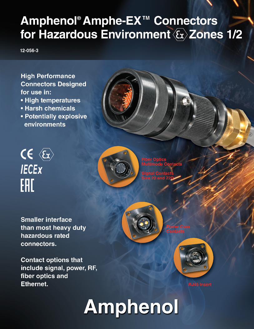
Amphenol technology provides innovation interconnect solutions for the demanding environmental requirements for equipment used in power generation, geophysical and oil and gas exploration. Sophisticated in-house testing facilities provide the qualification and specialization required for many of our connector products. Capabilities for testing include vibration and shock testing, humidity, engagement/separation force evaluation, durability testing, as well as salt spray/fog, optical and many other performance requirements.
Amphe-EX Series Mated Pair
1
INTRODUCTION
With the ever growing need for more power and sig- nal in a smaller interface in ATEX rated areas, Amphenol is pleased to introduce the Amphe-EX circular connector series.
Designed for Hazardous Environments
AMPHE-EX Connector Series is designed for use in ATEX and IECex rated areas. AMPHE-EX connectors are equipped to handle signal, power, RF or fiber optic requirements in the most harsh environments. AMPHE-EX connectors offer a complete array of insert patterns, ranging from 2 # 20 contacts, right up through 79 # 22D contacts, and everything in between.
In addition, AMPHE-EX is able to provide RJ45 connections and fiber optic termini into an ATEX and IECex approved interconnect solution.
Chemical Manufacturing, Pharmaceutical Manufacturing, Petrochemical Refineries, Land and Offshore Drilling Platforms are just a few of the areas that the new AMPHE-EX Series will provide increased performance.
AMPHE-EX connectors are made from machined aluminum components, and plated in a hard anodic coating designed to withstand the most extreme environments. Double-lead acme threads allow for a self cleaning mating action that does not clog under adverse conditions of ice, snow, mud or sand. The specific materials and design features of the AMPHE-EX series were originally selected to satisfy the stringent requirements of the Military and Aerospace industries. These connectors combine electrical and mechanical capabilities that equal or exceed many of the parameters established by the Military specification MIL-5015.
Amphenol Industrial, one of the leading interconnect suppliers to Industrial markets around the world, welcomes this new product to it’s current offering of harsh environment interconnect solutions.
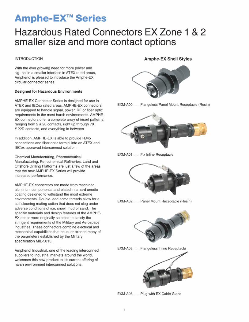
Amphe-EXTM SeriesHazardous Rated Connectors EX Zone 1 & 2smaller size and more contact options
Amphe-EX Shell Styles
EXM-A00. . . . Flangeless Panel Mount Receptacle (Resin)
EXM-A01 . . . .Fix Inline Receptacle
EXM-A02 . . . .Panel Mount Receptacle (Resin)
EXM-A03. . . . Flangeless Inline Receptacle
EXM-A06 . . . .Plug with EX Cable Gland

2
Amphe-EX connectors are Certified for EX Zone 1 and 2 (T6, T5 & T4)
Gases, Vapours and Mists - Ex de IIC Gb Tamb between -40°c to +55°c Fiber Optic OP PR - Ex op pr IIC Gb Tamb between -40°c to +55°c *Fiber Optic OP IS - Ex op is IIC Gb Tamb between -40°c to +55°c *Combustible Dusts - Ex tb IIIC Db (T80°c & T95°c) IP6X Tamb between -40°c to +55°c
ATEX Certified Zone 1 & 2- Cert. # SIRA 07ATEX1229X IECEx Certified Zone 1 & 2- Cert # SIR 08.0029XEAC Ex Zone 1 & 2- Cert # Cenelec IP68
HIGH TENSILE STRENGTH ALUMINUM: Bar Stock components precision machined, with points of impact designed for extra strength.
HARD ANODIC PLATING: All machined aluminum parts are finished with a hard, scratch resistant coating per Mil-A-8625, Type III. (300 days salt spray performance)
EASILY ACCESSIBLE WIRE TERMINALS: Conductors are readily terminated to contacts. Cable housings are slipped over conductors after terminating. Cumbersome handling and seating of inserts with conductors attached is eliminated.
LARGE WIRE SPACING: Ample wire space is provided in cable housings and hardware.
CABLE OPTIONS: Cable Gland terminations available to allow variety of cable types including unarmored, armored and sheathed cable built to the IEEE-45, UL1309, IEC, BS, DIN and JIC standards. Flexible cables like SOOW-A, W, G-GC and DLO constructions can also be used with the AMPHE-EX series connectors. For Cable Gland information, ask for Amphenol Cable Glands and Cord Grips catalog # 12- 055.
INSERT VARIATIONS: A broad variety of inserts are offered ranging from 2 # 20 awg, up to 79 # 22D awg contacts. Numerous hybrid inserts available that offer combination copper and Coax/Twinax. In addition, Fiber Optic and RJ45 options available.
RoHS COMPLIANT PRODUCT
Contact SizeTest Current Maximum
Millivolt Drop Crimp*
Crimp Well Data
Crimp Crimp Barrel Diameter
Cable Range AWG / SQMM
22D 5 73 .0345” (.0876mm) 22-26 / 0.25-0.3420 7.5 55 .047” (1.194mm) 20-24 / 0.5-0.7516 13 49 .067” (1.701mm) 16-20 / 1.0-1.512 23 42 .100” (2.540mm) 12-14 / 2.5
10 (Power) 33 33 .137” (3.480mm) 10-12 / 4.0-6.0Measurements in inches ± .0010 size 22D to size 16 and ± .002 for size 12 and 10Measurements in mm ± .0025 size 22D to size 16 and ± .050 for size 12 and 10
CONTACT RATING
Amphe-EXTM SeriesSpecifications
Service RatingSuggested Operating Voltage
(Sea Level) Test Voltage (Sea Level)AC (RMS) DC
M 400 550 1300 VRMSN 300 450 1000 VRMSI 600 850 1800 VRMSII 900 1250 2300 VRMS
** Please note that the establishment of electrical factors is left entirely in the designers hands, since they are in the best position to know what voltage, switching surges, transients, etc. can be expected in a particular circuit.
SERVICE RATING
3
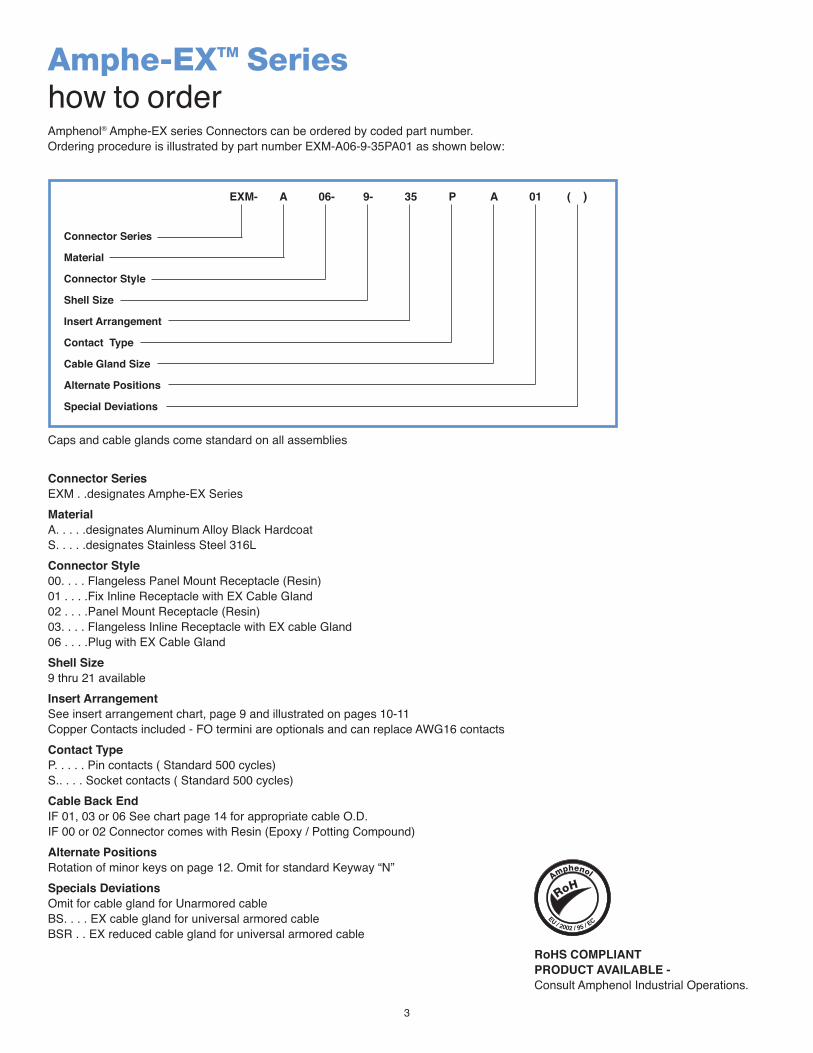
Connector SeriesEXM . .designates Amphe-EX SeriesMaterialA. . . . .designates Aluminum Alloy Black Hardcoat S. . . . .designates Stainless Steel 316LConnector Style00. . . . Flangeless Panel Mount Receptacle (Resin) 01 . . . .Fix Inline Receptacle with EX Cable Gland 02 . . . .Panel Mount Receptacle (Resin)03. . . . Flangeless Inline Receptacle with EX cable Gland 06 . . . .Plug with EX Cable GlandShell Size9 thru 21 availableInsert ArrangementSee insert arrangement chart, page 9 and illustrated on pages 10-11Copper Contacts included - FO termini are optionals and can replace AWG16 contactsContact TypeP. . . . . Pin contacts ( Standard 500 cycles)S.. . . . Socket contacts ( Standard 500 cycles)Cable Back EndIF 01, 03 or 06 See chart page 14 for appropriate cable O.D.IF 00 or 02 Connector comes with Resin (Epoxy / Potting Compound)Alternate PositionsRotation of minor keys on page 12. Omit for standard Keyway “N”Specials DeviationsOmit for cable gland for Unarmored cableBS. . . . EX cable gland for universal armored cableBSR . . EX reduced cable gland for universal armored cable
Amphenol® Amphe-EX series Connectors can be ordered by coded part number. Ordering procedure is illustrated by part number EXM-A06-9-35PA01 as shown below:
Amphe-EXTM Serieshow to order
Connector Series
Material
Connector Style
Shell Size
Insert Arrangement
Contact Type
Cable Gland Size
Alternate Positions
Special Deviations
EXM- A 06- 9- 35 P A 01 ( )
Caps and cable glands come standard on all assemblies
RoHS COMPLIANT PRODUCT AVAILABLE - Consult Amphenol Industrial Operations.
4
Shell Size AFlange Dimension
BMounting Dimension
CThread Adapter
9 1.658 (42,11) 2.058 (52,27) .750 NPT (M25)11 1.786 (45,36) 2.180 (55,37) .750 NPT (M25)13 1.900 (48,26) 2.366 (60,09) 1.00 NPT (M32)15 2.025 (51,43) 2.454 (62,33) 1.00 NPT (M32)17 2.150 (54,61) 2.576 (65,43) 1.25 NPT (M40)19 2.256 (57,30) 2.698 (68,52) 1.25 NPT (M40)21 2.381 (60,47) 2.819 (71,60) 1.25 NPT (M40)
All dimensions for reference only.
Inches (Millimeters)
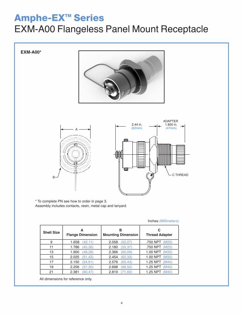
Amphe-EXTM SeriesEXM-A00 Flangeless Panel Mount Receptacle
EXM-A00*
A
BC THREAD
ADAPTER
Amphe-EXEXM-A00 Flangeless Panel Mount Receptacle
2.44 in.(62mm)
1.850 in.(47mm)
* To complete PN see how to order in page 3.Assembly includes contacts, resin, metal cap and lanyard.
5
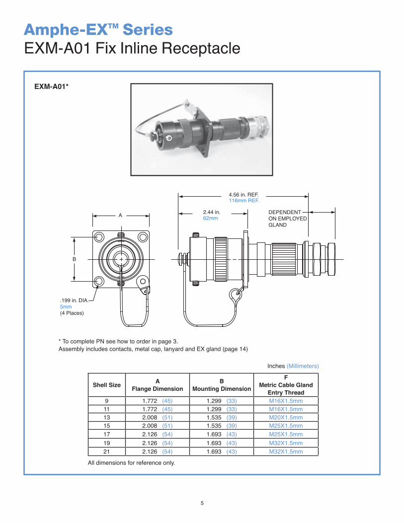
Amphe-EXTM SeriesEXM-A01 Fix Inline Receptacle
Shell Size AFlange Dimension
BMounting Dimension
FMetric Cable Gland
Entry Thread9 1.772 (45) 1.299 (33) M16X1.5mm11 1.772 (45) 1.299 (33) M16X1.5mm13 2.008 (51) 1.535 (39) M20X1.5mm15 2.008 (51) 1.535 (39) M25X1.5mm17 2.126 (54) 1.693 (43) M25X1.5mm19 2.126 (54) 1.693 (43) M32X1.5mm21 2.126 (54) 1.693 (43) M32X1.5mm
All dimensions for reference only.
Inches (Millimeters)
EXM-A01*
B
A
4.56 in. REF.
DEPENDENTON EMPLOYEDGLAND
116mm REF.
.199 in. DIA.5mm(4 Places)
Amphe-EXEXM-A01 Fix Inline Receptacle
* To complete PN see how to order in page 3.
Assembly includes contacts, metal cap, lanyard and EX gland (page 14)
2.44 in.62mm
* To complete PN see how to order in page 3.Assembly includes contacts, metal cap, lanyard and EX gland (page 14)
6
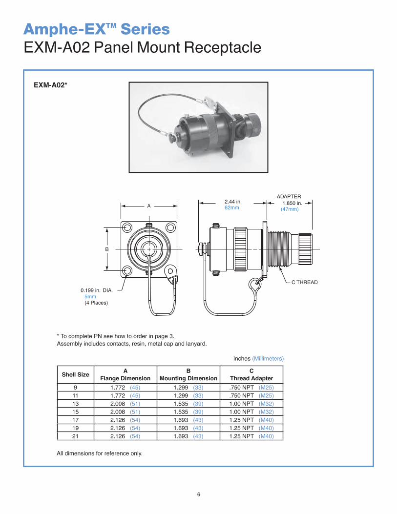
Amphe-EXTM SeriesEXM-A02 Panel Mount Receptacle
Shell Size AFlange Dimension
BMounting Dimension
CThread Adapter
9 1.772 (45) 1.299 (33) .750 NPT (M25)11 1.772 (45) 1.299 (33) .750 NPT (M25)13 2.008 (51) 1.535 (39) 1.00 NPT (M32)15 2.008 (51) 1.535 (39) 1.00 NPT (M32)17 2.126 (54) 1.693 (43) 1.25 NPT (M40)19 2.126 (54) 1.693 (43) 1.25 NPT (M40)21 2.126 (54) 1.693 (43) 1.25 NPT (M40)
All dimensions for reference only.
Inches (Millimeters)
EXM-A02*
2.44 in.62mmA
B
C THREAD0.199 in. DIA.
5mm(4 Places)
ADAPTER
Amphe-EXEXM-A02 Panel Mount Receptacle
* To complete PN see how to order in page 3.
1.850 in.(47mm)
Assembly includes contacts, resin, metal cap and lanyard. * To complete PN see how to order in page 3.Assembly includes contacts, resin, metal cap and lanyard.
7
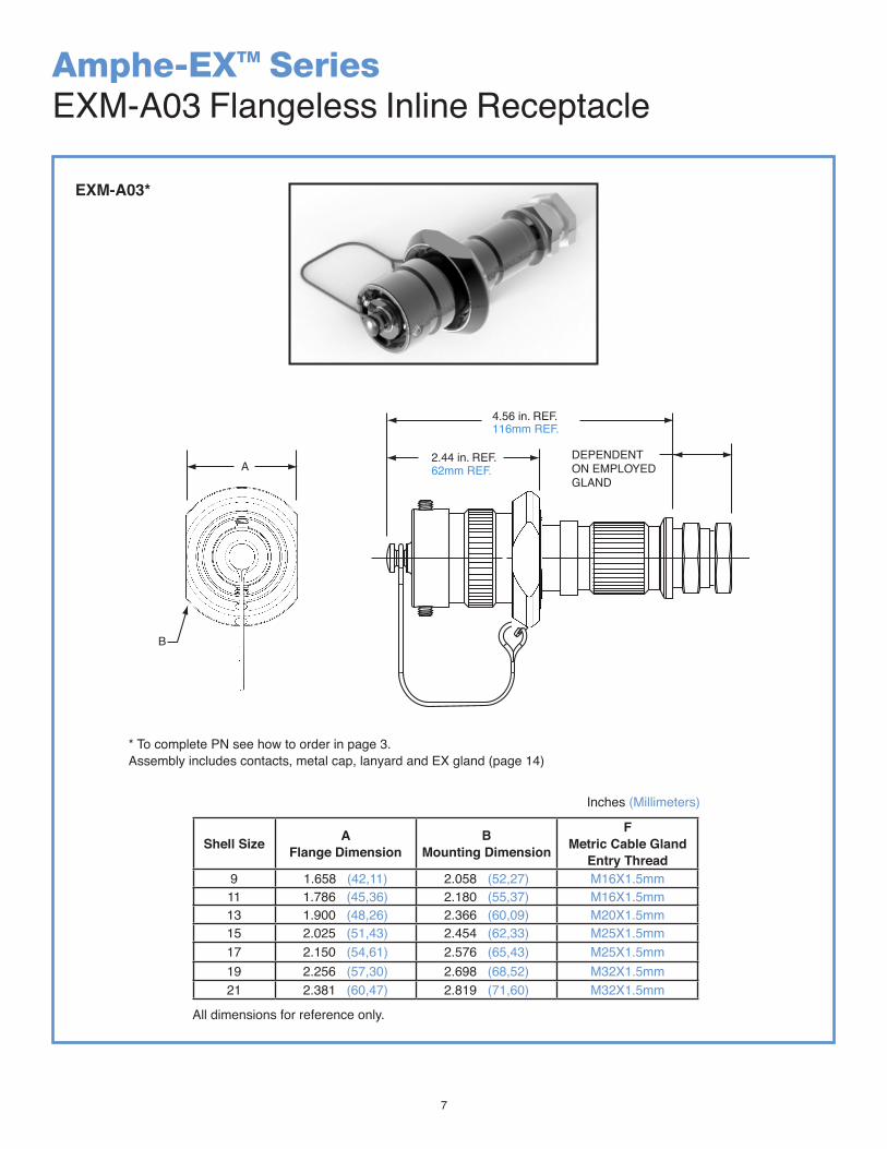
Amphe-EXTM SeriesEXM-A03 Flangeless Inline Receptacle
All dimensions for reference only.
Shell Size AFlange Dimension
BMounting Dimension
FMetric Cable Gland
Entry Thread9 1.658 (42,11) 2.058 (52,27) M16X1.5mm11 1.786 (45,36) 2.180 (55,37) M16X1.5mm13 1.900 (48,26) 2.366 (60,09) M20X1.5mm15 2.025 (51,43) 2.454 (62,33) M25X1.5mm17 2.150 (54,61) 2.576 (65,43) M25X1.5mm19 2.256 (57,30) 2.698 (68,52) M32X1.5mm21 2.381 (60,47) 2.819 (71,60) M32X1.5mm
Inches (Millimeters)
EXM-A03*
4.56 in. REF.
2.44 in. REF. DEPENDENTON EMPLOYEDGLAND
62mm REF.
116mm REF.
Amphe-EXEXM-A03 Flangeless Inline Receptacle
A
B
* To complete PN see how to order in page 3.Assembly includes contacts, metal cap, lanyard and EX gland (page 14)* To complete PN see how to order in page 3.Assembly includes contacts, metal cap, lanyard and EX gland (page 14)
8
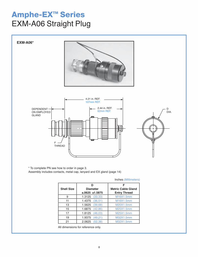
Amphe-EXTM SeriesEXM-A06 Straight Plug
Shell SizeD
Diameter±.0625 ±1.5875
FMetric Cable Gland
Entry Thread9 1.3125 (33,33) M16X1.5mm11 1.4375 (36,51) M16X1.5mm13 1.5625 (39,68) M20X1.5mm15 1.6875 (42,86) M25X1.5mm17 1.8125 (46,03) M25X1.5mm19 1.9375 (49,21) M32X1.5mm21 2.0625 (52,38) M32X1.5mm
All dimensions for reference only.
Inches (Millimeters)
EXM-A06*
2.44 in. REF.62mm REF.
107mm REF.4.21 in. REF.
DDIA.
FTHREAD
DEPENDENTON EMPLOYEDGLAND
Amphe-EXEXM-A06 straight plug
* To complete PN see how to order in page 3.Assembly includes contacts, metal cap, lanyard and EX gland (page 14)* To complete PN see how to order in page 3.
Assembly includes contacts, metal cap, lanyard and EX gland (page 14)
9
ShellSize/Arrg.
Service Rating
TotalConatcts
Contact Size
22D 20 16 12 12(coax)
10(power)
8(coax)
8†† (Twinax)
9-35 M 6 69-94 M 2 29-98 I 3 311-2 I 2 211-5 I 5 511-35 M 13 1311-98 I 6 611-99 I 7 713-4 I 4 413-8 I 8 813-13 I, Fiber Optic 4 2* 213-35 M 22 2213-98 I 10 1013-71 I 2 215-2 I 2 215-5 II 5 515-15 I 15 14 115-18 I 18 1815-19 I 19 1915-35 M 37 3715-97 I 12 8 415-AC M 26 24 217-2 M 39 38 117-6 I 6 617-8 II 8 817-22 NA 4 2 217-26 I 26 2617-31 M 19 4 11 417-35 M 55 5517-99 I 23 21 219-11 II 11 1119-31 M 15 12 1 219-32 I 32 3219-35 M 66 6619-RJ CAT 5/621-11 I 11 1121-16 II 16 1621-35 M 79 7921-39 I 39 37 221-41 I 41 4121-75 M 4 2
Amphe-EXTM Seriesinsert availability and identification, contacts, sealing plugs
CONTACTS SEALING PLUGSConatct
SizePin
Part NumberSocket
Part NumberContact
SizeProprietary
No.8 (Coax) 21-33102-21 21-33101-21 8 (Coax) 10-482099-8
8 (Twinax) 21-33190-529 21-33191-530 8 (Twinax) T3-4008-59P10 (Power) 10-597448-105 10-597449-105 10 (Power) 10-576225
12 10-597448-125 10-597449-125 12 10-405996-12116 10-597448-165 10-597449-165 16 10-405996-16120 10-597448-205 10-597449-205 20 10-405996-201
22D 10-597448-725 10-597449-452 22D 10-405996-221
STANDARD CONTACTS AND SEALING PLUGS FOR AMPHE-EX SERIES
Above part numbers include standard 500 cycle finish designation - gold plating over suitable underplate in accordance with MIL-C-39029. For other contact options available for use in Amphe-EX connectors, (thermocouple) consult Amphenol, Sidney, NY.

10
Amphe-EXTM Seriesinsert arrangements
5 164
32
B A
CA
B
AB
CDE
12
34
567
89
101131 21
ABE F
A
BCD
EFG
AB
C
DA
B
CD
E
FG
H
1
2122
AB
CD
E
AB
C
DE
FG
HJ
KL
MNP
R
AB
CD
EFGH
J
KL
M NP
RS
T U
AB
C
DEF GH
J
K
LM
N P
R
ST
U V
1
2131A
BC
DEF
G
H
JK
L
M
1
6
11
17
30
A
B
C
D
E
F
A
B
C
DE
F
GH
1
3
4
9
10
16
17
24
25
31
32
39
4047
46
52
53
55
A BC
D
EFG
HJKL
M
N
PR
S T U
VWX
YZ
A
D
C
B
A BC
D
E
FGHJ
KLM
N
PR
S TU
VW
XY
Z
a b
c
ABC
D
B
C
D
LM N
P
V
UK
JT RH
GF
ES
23
45
67
8 910
11
1213
1415 16
1718
19
20
2326
2122
2425
Amphe-EXinsert arrangements
8 10 12 16 20 22D
D C
AB
CD
EF
GH
JK
Insert Arrangement 9-35 9-94 9-98 11-2 11-5 11-35 11-98 11-99Service Rating M M I I I M I INumber of Contacts 6 2 3 2 5 13 6 7Contact Size AWG 22D 20 20 16 20 22D 20 20
Insert Arrangement 13-4 13-8 13-13 13-35 13-98 15-5 15-15 15-18Service Rating I I I, Fiber Optic M I II I INumber of Contacts 4 8 2 2 22 10 5 14 1 18Contact Size AWG 16 20 16 12 22D 20 16 20 16 20
Dedicated toFiber Optics
Insert Arrangement 15-19 15-35 15-97 15-AC 17-2 17-6Service Rating I M I M M INumber of Contacts 19 37 8 4 24 2 38 1 6Contact Size AWG 20 22D 20 16 22D 16 22D 8 Twinax 12
Insert Arrangement 17-8 17-22 17-26 17-31 17-35 17-99Service Rating II Coax I M M INumber of Contacts 8 2 2 2 4 11 4 4 21 2Contact Size AWG 16 12 Coax 8 Coax 20 22D 20 16 16 20 16
CONTACT LEGENDNote: Size 8 cavities can be supplied with either twinax or coax per customer requirement.
front face of pin inserts illustrated
*please check crimp well diameter on page 2

11
Amphe-EXTM Seriesinsert arrangements
5 164
32
B A
CA
B
AB
CDE
12
34
567
89
101131 21
ABE F
A
BCD
EFG
AB
C
DA
B
CD
E
FG
H
1
2122
AB
CD
E
AB
C
DE
FG
HJ
KL
MNP
R
AB
CD
EFGH
J
KL
M NP
RS
T U
AB
C
DEF GH
J
K
LM
N P
R
ST
U V
1
2131A
BC
DEF
G
H
JK
L
M
1
6
11
17
30
A
B
C
D
E
F
A
B
C
DE
F
GH
1
3
4
9
10
16
17
24
25
31
32
39
4047
46
52
53
55
A BC
D
EFG
HJKL
M
N
PR
S T U
VWX
YZ
A
D
C
B
A BC
D
E
FGHJ
KLM
N
PR
S TU
VW
XY
Z
a b
c
ABC
D
B
C
D
LM N
P
V
UK
JT RH
GF
ES
23
45
67
8 910
11
1213
1415 16
1718
19
20
2326
2122
2425
Amphe-EXinsert arrangements
8 10 12 16 20 22D
D C
AB
CD
EF
GH
JK
Insert Arrangement 19-11 19-31 19-32 19-35 19-RJService Rating II M I M CAT5-CAT6Number of Contacts 11 2 1 12 32 66 ETHERNETContact Size AWG 16 8 Coax 12 22D 20 22D
Insert Arrangement 15-19 15-35 15-97 15-AC 17-2 17-6Service Rating I M I M M INumber of Contacts 19 37 8 4 24 2 38 1 6Contact Size AWG 20 22D 20 16 22D 16 22D 8 Twinax 12
Insert Arrangement 17-8 17-22 17-26 17-31 17-35 17-99Service Rating II Coax I M M INumber of Contacts 8 2 2 2 4 11 4 4 21 2Contact Size AWG 16 12 Coax 8 Coax 20 22D 20 16 16 20 16
Insert Arrangement 19-68 21-11 21-16 21-35Service Rating I I II MNumber of Contacts 18 11 16 79Contact Size AWG 16 12 16 22D
Insert Arrangement 21-39 21-41 21-75Service Rating I I MNumber of Contacts 37 2 41 4Contact Size AWG 20 16 20 8 Coax
CONTACT LEGENDNote: Size 8 cavities can be supplied with either twinax or coax per customer requirement.
front face of pin inserts illustrated
*please check crimp well diameter on page 2 *please check crimp well diameter on page 2
A
B
C
D
E
F
G
H
J
K
L
A
BC
EK
M
N
RS
U
VW
gh
f AB
C
D
E
FG
HJ
KL
M
N
P
RS
TU
V
W
X
YZa
bc
d
ef
gh
j1
2
3
4
9
10
16
17
24
25
33
34
42
43
50
51
57
58
63
64
66
A
B
C
D
E
F
G
H
J
KL
A
B
C
D
EF
G
H
J
K
L
MN
PR
S
1
11
21
31
41
51
61 71
79
AB
CD
E
FG
HJKL
M
NP
R
ST
UV W
XY
Zab
cd
ef
gh
ij
km
n
p
qr
A BC
D
E
F
G
HJ
KLMN
P
R
S
T
UV W
XY
Z
a
bc
def
g
h
ij
km
npq
r
st
A
BC
D
ABL
CK
DJ
EH
FR
U
M
T N
S P
G

12
MAINKEYWAY
ARBSC
BRBSC
CRBSC
DRBSC
˚
˚
˚˚
MAINKEYWAY
APBSC̊
BPBSC̊
CPBSC̊
DPBSC̊
Amphe-EXTM Seriesstandard insert alternate positioning
A plug with a given rotation letter will mate with a receptacle with the same rotation letter. The angles for a given connector are the same whether it contains pins or sockets. Inserts are not rotated in conjunction with the master key/keyway.
RECEPTACLE(front face shown)
PLUG(front face shown)
Shell Size
Key & keywayarrangementidentification
letter
AR°or
AP°BSC
BR°or
BP°BSC
CR°or
CP°BSC
DR°or
DP°BSC
9
N0102030405
10510280356491
140132118140155131
215248230205234197
265320312275304240
11,13,and15
N0102030405
95113905311951
141156145156146141
208182195220176184
236292252255298242
17and19
N0102030405
8013549666279
142170169140145153
196200200200180197
293310244257280272
21,23,and25
N0102030405
8013549666279
142170169140145153
196200200200180197
293310244257280272
MASTER KEY/KEYWAY POSITION
13
EXM A06 19 RJF A BS LXXEXM–A06–19–RJF–A–BS–LXX
Amphe-EXTM Serieswith RJ45
In addition to a complete line of power and signal inserts, the Amphe-EX also offersRJ45 ethernet connection systems. The Amphe-EX RJ45 assemblies offer all the sameperformance characteristics as the standard Amphe-EX hardware.
The Amphe-EX with RJ45 allows you to use an Ethernet Class 5/Cat. 5e connection for 10Base T, 100 BaseTX or 1000 BaseT networks in hazardous environments. With the patented RJStop® system, you can use the standard RJ45 cordset in our Amphe-EX connector sets which will provide a flame-proof protection system.
Connector Style00=Flangeless Panel Mount Receptacle01=Fix Inline Receptacle02=Panel Mount Receptacle (standard)03=Flangeless Inline Receptacle06=Plug
RJ2 for 06Picture 1
RJ1 for 06Picture 2
RJ2 for 01/03Picture 4
RJF for 02/00Picture 5
Insert TypeRJ2= Picture 1 or 4RJ1= Picture 2RJF-00=Picture 3RJF= Picture 5
Cable TypeBlank for unarmoredBS for armored cable
Material A= Aluminum (Standard)S= Stainless Steel
Cable lengthL05=0.5 meterL15=1.5 meter
EX Gland sizeProduct Series
RJF-00 for 02/00Picture 4
14
Amphe-EXTM Seriescable glands
Amphenol offers an extensive line of explosion proof and generalduty cable glands. Consult Amphenol Industrial Operations and ask for new catalog 12-055, Amphenol Cable Glands and Cord Grips.
EX-35 glands provide a single pull resistant seal on theouter sheath of unarmored cable.
EX-20 provide a seal on the inner and outer sheath,an entry thread seal with a universal armor clamp.
Fiber Optic Custom Cable AssemblyDesign and Fabrication
Amphenol’s cable assembly expertise dates back to the first industry standard fiber optic connector, over 25 years ago. Our depth of understanding of connector and termini design, and the complete control of connector materials, make Amphenol Fiber Optic cable assemblies one of the best in the industry. Amphenol offers a comprehensive line of single mode and multi-mode cable assemblies in a variety of cable configurations. From simplex jumpers to multi-fiber custom assemblies, Amphenol can design and supply all of your cable needs.
High quality polishing processes have been developed to meet and exceed industry standard specifications for insertion loss, return loss and endface geometry. All assemblies are designed to intermateability standards for optical and physical performance criteria.
Amphenol can assemble, polish and test many harshenvironment and commercial grade connectors including:
MIL-PRF-29504 standardMTC/MP0 (for availability, consult Amphenol Industrial)
Shell size 9 and 11 can only accept A1 gland typeShell size 13 can only accept A1 A2 and A gland type
EEx d Cable Gland Size
Unarmored CableNo deviation if Unarmored
Armored & Sheathed Cable-BS Armored & Sheathed with reduced bore
Under Armor Standard Outer Diameter OD-ReducedMin Max Min Max Min Max Min Max
A1 .1575 (4.0) .3307 (8.4) .1339 (3.4) .3307 (8.4) .3543 (9.0) .5315 (13.5) .2638 (6.7) .4055 (10.3)A2 .2835 (7.2) .4606 (11.7) .2835 (7.2) .4606 (11.7) .4528 (11.5) .6299 (16.0) .3701 (9.4) .4921 (12.5)A .3780 (9.6) .5512 (14.0) .3701 (9.4) .5512 (14.0) .6102 (15.5) .8307 (21.1) .4724 (12.0) .6929 (17.6)B .5315 (13.5) .7874 (20.0) .5315 (13.5) .7874 (20.0) .7992 (20.3) 1.079 (27.4) .6614 (16.8) .9409 (23.9)C .7677 (19.5) 1.035 (26.3) .7677 (19.5) 1.035 (26.3) 1.051 (26.7) 1.339 (34.0) .9134 (23.2) 1.201 (30.5)
Inches (Millimeters)
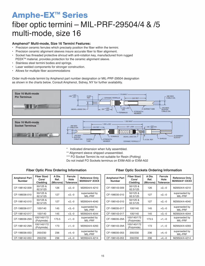
15
Amphe-EXTM Seriesfiber optic termini – MIL-PRF-29504/4 & /5multi-mode, size 16Amphenol® Multi-mode, Size 16 Termini Features:• Precision ceramic ferrules which precisely position the fiber within the termini.• Precision ceramic alignment sleeves insure accurate fiber to fiber alignment.• Socket has threaded protective shroud with anti-rotation key, manufactured from rugged PEEKTM material, provides protection for the ceramic alignment sleeve.• Stainless steel termini bodies and springs.• Laser welded components for stronger construction.• Allows for multiple fiber accommodations
Order multi-mode termini by Amphenol part number designation or MIL-PRF-29504 designationas shown in the charts below. Consult Amphenol, Sidney, NY for further availability.
* Indicated dimension when fully assembled.** Alignment sleeve shipped unassembled.*** FO Socket Termini its not suitable for Resin (Potting) Do not install FO Sockets terminus on EXM-A00 or EXM-A02
1.176 MAX.*
CERAMIC FERRULEA DIA.REF.
.102 ±.001DIA..06248 ±.00002 DIA. .297 +.003
–.002STRENGTHMEMBER
SHRINK TUBE .040 MAX.BUFFERCABLE DIA.
.080 MAX.CABLE DIA.
TERMINUS
.525 REF..128 +.002
–.001
SHRINKTUBE
STRENGTHMEMBER
.06248 ±.0002 DIA.TERMINUS
CERAMIC FERRULEA DIA. REF.
.128 DIA.+.002–.001
ALIGNMENTSHROUD SLEEVE**
1.093 ±.020.080 MAX
CABLE DIA.
.040 MAXBUFFERCABLE DIA.
1.500 MAX*
.537 ±.008.525 REF.
Size 16 Multi-modeSocket Terminus
Size 16 Multi-modePin Terminus
***
Amphenol Part Number
Fiber Size† Core/
Cladding
A Dia. Ref.
(Microns)
Ferrule Hole
ToleranceReference Only M29504/4*-XXXX
CF-198142-009 50/125 &62.5/125 126 +2,–0 M29504/4-4210
CF-198036-010 50/125 & 62.5/125 127 +2,–0 superseded by
MIL-PRF
CF-198142-010 50/125 & 62.5/125 127 +2,–0 M29504/4-4040
CF-198036-017 100/140 145 +3,–0 superseded by MIL-PRF
CF-198142-017 100/140 145 +3,–0 M29504/4-4044
CF-198036-29A 100/140/172(Polyimide) 173.5 +1,–0 superseded by
MIL-PRF
CF-198142-29A 100/140/172(Polyimide) 173 +1,–0 M29504/4-4293
CF-198036-053 200/230 236 +4,–0 superseded by MIL-PRF
CF-198142-053 200/230 236 +4,–0 M29504/4-4214
Amphenol Part Number
Fiber Size† Core/
Cladding
A Dia. Ref.
(Microns)
Ferrule Hole
ToleranceReference Only M29504/4*-XXXX
CF-198143-009 50/125 &62.5/125 126 +2,–0 M29504/4-4210
CF-198035-010 50/125 & 62.5/125 127 +2,–0 superseded by
MIL-PRF
CF-198143-010 50/125 & 62.5/125 127 +2,–0 M29504/4-4040
CF-198035-017 100/140 145 +3,–0 superseded by MIL-PRF
CF-198143-017 100/140 145 +3,–0 M29504/4-4044
CF-198035-29A 100/140/172(Polyimide) 173.5 +1,–0 superseded by
MIL-PRF
CF-198143-29A 100/140/172(Polyimide) 173 +1,–0 M29504/4-4293
CF-198035-053 200/230 236 +4,–0 superseded by MIL-PRF
CF-198143-053 200/230 236 +4,–0 M29504/4-4214
Fiber Optic Pins Ordering Information Fiber Optic Sockets Ordering Information
Inches (Millimeters)
16
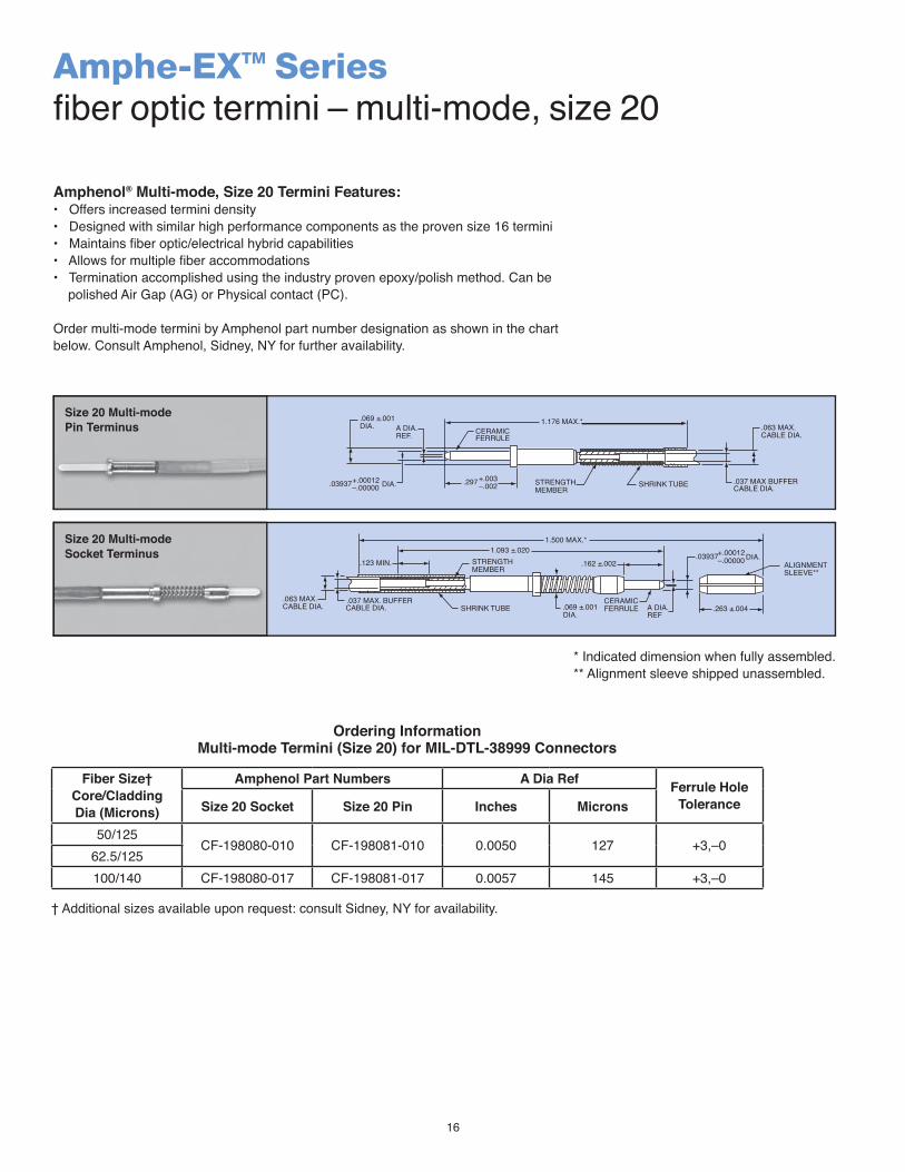
Amphe-EXTM Seriesfiber optic termini – multi-mode, size 20
Amphenol® Multi-mode, Size 20 Termini Features:• Offers increased termini density• Designed with similar high performance components as the proven size 16 termini• Maintains fiber optic/electrical hybrid capabilities• Allows for multiple fiber accommodations• Termination accomplished using the industry proven epoxy/polish method. Can be polished Air Gap (AG) or Physical contact (PC).
Order multi-mode termini by Amphenol part number designation as shown in the chartbelow. Consult Amphenol, Sidney, NY for further availability.
+.00012.03937–.00000 DIA.
.069 ±.001DIA. A DIA.
REF. CERAMICFERRULE
1.176 MAX.*
SHRINK TUBE .037 MAX BUFFERCABLE DIA.
.063 MAX.CABLE DIA.
STRENGTHMEMBER
.297+.003–.002
.263 ±.004
.03937+.00012–.00000 DIA.
ALIGNMENTSLEEVE**
A DIA.REF
CERAMICFERRULE
.162 ±.002
1.500 MAX.*
.069 ±.001DIA.
1.093 ±.020STRENGTHMEMBER
SHRINK TUBE.037 MAX. BUFFERCABLE DIA.
.063 MAX.CABLE DIA.
.123 MIN.
Size 20 Multi-modeSocket Terminus
Size 20 Multi-modePin Terminus
* Indicated dimension when fully assembled.** Alignment sleeve shipped unassembled.
Fiber Size† Core/Cladding Dia (Microns)
Amphenol Part Numbers A Dia Ref Ferrule Hole ToleranceSize 20 Socket Size 20 Pin Inches Microns
50/125CF-198080-010 CF-198081-010 0.0050 127 +3,–0
62.5/125100/140 CF-198080-017 CF-198081-017 0.0057 145 +3,–0
† Additional sizes available upon request: consult Sidney, NY for availability.
Ordering InformationMulti-mode Termini (Size 20) for MIL-DTL-38999 Connectors
17
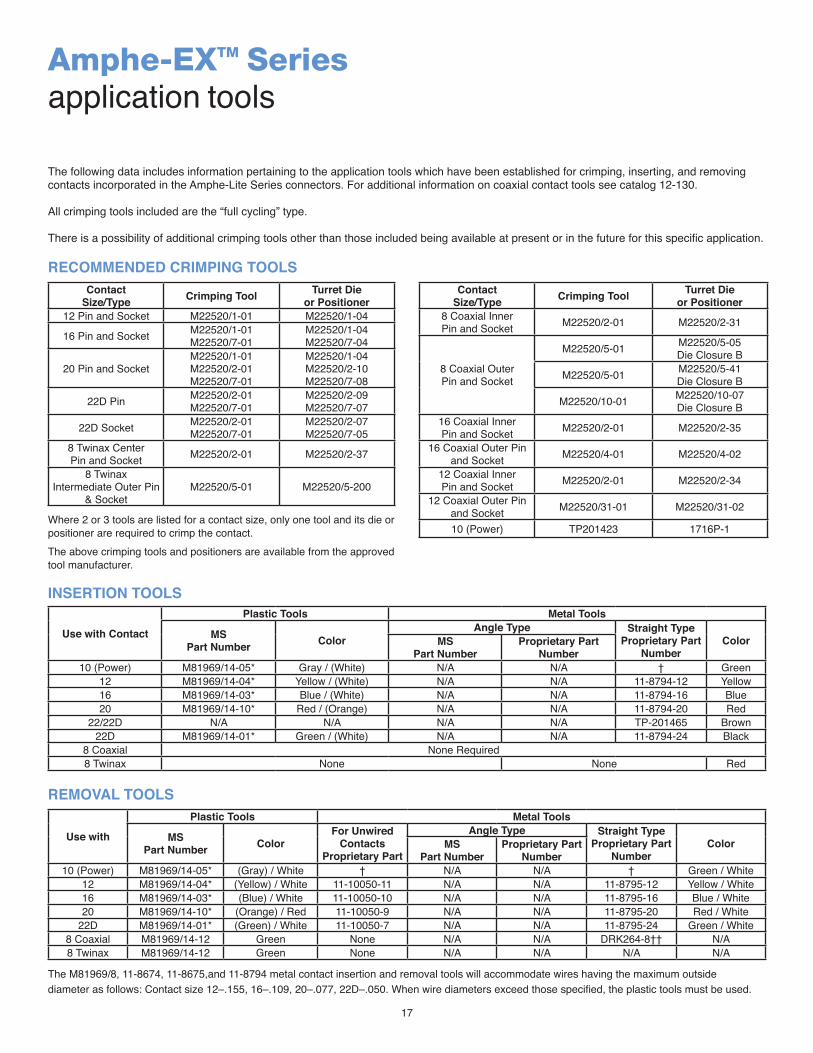
Amphe-EXTM Seriesapplication tools
* Indicated dimension when fully assembled.** Alignment sleeve shipped unassembled.
ContactSize/Type Crimping Tool Turret Die
or Positioner12 Pin and Socket M22520/1-01 M22520/1-04
16 Pin and Socket M22520/1-01 M22520/7-01
M22520/1-04 M22520/7-04
20 Pin and SocketM22520/1-01 M22520/2-01 M22520/7-01
M22520/1-04 M22520/2-10 M22520/7-08
22D Pin M22520/2-01 M22520/7-01
M22520/2-09 M22520/7-07
22D Socket M22520/2-01 M22520/7-01
M22520/2-07 M22520/7-05
8 Twinax Center Pin and Socket M22520/2-01 M22520/2-37
8 Twinax Intermediate Outer Pin
& SocketM22520/5-01 M22520/5-200
ContactSize/Type Crimping Tool Turret Die
or Positioner8 Coaxial Inner Pin and Socket M22520/2-01 M22520/2-31
8 Coaxial Outer Pin and Socket
M22520/5-01 M22520/5-05Die Closure B
M22520/5-01 M22520/5-41Die Closure B
M22520/10-01 M22520/10-07Die Closure B
16 Coaxial Inner Pin and Socket M22520/2-01 M22520/2-35
16 Coaxial Outer Pin and Socket M22520/4-01 M22520/4-02
12 Coaxial Inner Pin and Socket M22520/2-01 M22520/2-34
12 Coaxial Outer Pin and Socket M22520/31-01 M22520/31-02
10 (Power) TP201423 1716P-1Where 2 or 3 tools are listed for a contact size, only one tool and its die or positioner are required to crimp the contact.The above crimping tools and positioners are available from the approved tool manufacturer.
The following data includes information pertaining to the application tools which have been established for crimping, inserting, and removing contacts incorporated in the Amphe-Lite Series connectors. For additional information on coaxial contact tools see catalog 12-130.
All crimping tools included are the “full cycling” type.
There is a possibility of additional crimping tools other than those included being available at present or in the future for this specific application.
Use with Contact
Plastic Tools Metal Tools
MSPart Number Color
Angle Type Straight Type Proprietary Part
NumberColorMS
Part NumberProprietary Part
Number10 (Power) M81969/14-05* Gray / (White) N/A N/A † Green
12 M81969/14-04* Yellow / (White) N/A N/A 11-8794-12 Yellow16 M81969/14-03* Blue / (White) N/A N/A 11-8794-16 Blue20 M81969/14-10* Red / (Orange) N/A N/A 11-8794-20 Red
22/22D N/A N/A N/A N/A TP-201465 Brown22D M81969/14-01* Green / (White) N/A N/A 11-8794-24 Black
8 Coaxial None Required8 Twinax None None Red
The M81969/8, 11-8674, 11-8675,and 11-8794 metal contact insertion and removal tools will accommodate wires having the maximum outside diameter as follows: Contact size 12–.155, 16–.109, 20–.077, 22D–.050. When wire diameters exceed those specified, the plastic tools must be used.
RECOMMENDED CRIMPING TOOLS
INSERTION TOOLS
REMOVAL TOOLS
Use with
Plastic Tools Metal Tools
MSPart Number Color
For Unwired Contacts
Proprietary Part
Angle Type Straight Type Proprietary Part
NumberColorMS
Part NumberProprietary Part
Number10 (Power) M81969/14-05* (Gray) / White † N/A N/A † Green / White
12 M81969/14-04* (Yellow) / White 11-10050-11 N/A N/A 11-8795-12 Yellow / White16 M81969/14-03* (Blue) / White 11-10050-10 N/A N/A 11-8795-16 Blue / White20 M81969/14-10* (Orange) / Red 11-10050-9 N/A N/A 11-8795-20 Red / White
22D M81969/14-01* (Green) / White 11-10050-7 N/A N/A 11-8795-24 Green / White8 Coaxial M81969/14-12 Green None N/A N/A DRK264-8†† N/A8 Twinax M81969/14-12 Green None N/A N/A N/A N/A

18
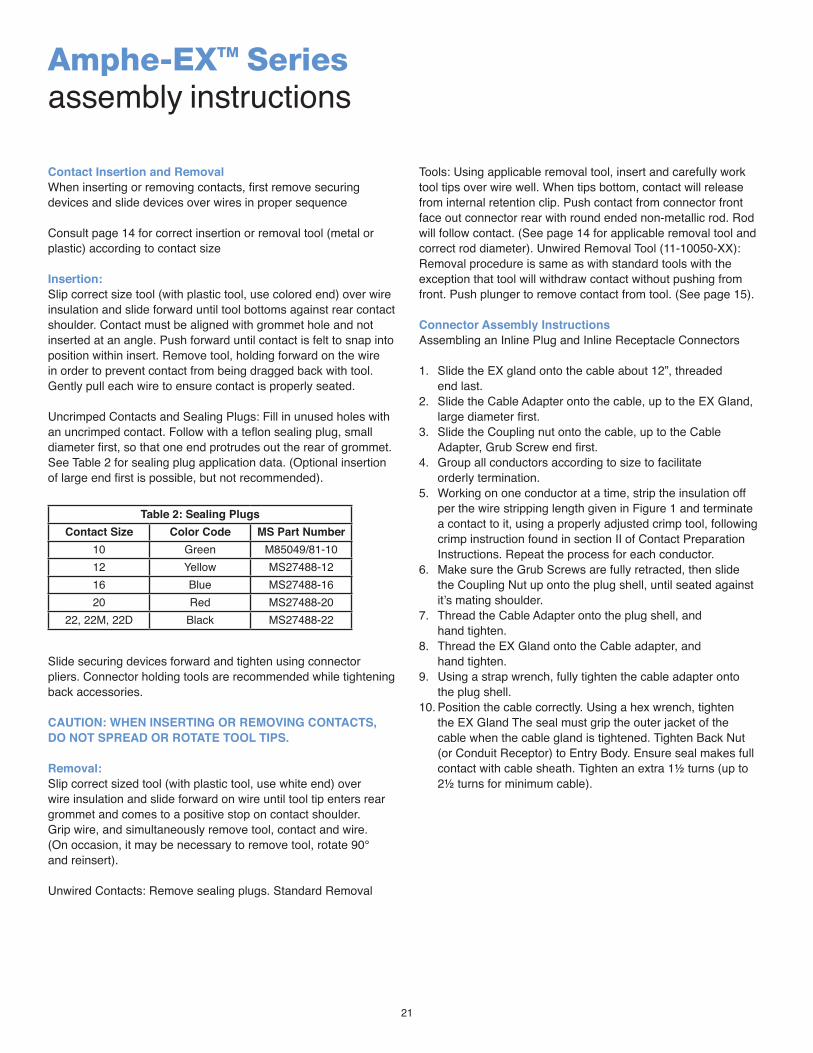
Amphe-EXTM Seriesassembly instructions
1. Read manufacturer’s assembly instructions before actually starting to assemble connectors. Besides the matter of instruction on correct procedures, there are two important reasons for this preliminary step: To identify the various component parts, and to check for any missing parts.
2. Cut cable jacket and sheathing squarely and sheathing squarely and to correct length, using only wire strippers that have been approved for the operation. In preparing the individual wires in cables and harnesses for assembly, make allowances in length for reaching the outer most circle of contacts cavities in the conductors. The insulation should be cut progressively longer as they extend out from the center of the cable or harness to assure sufficient length.
3. Follow chart on Page 5 covering maximum cable stripping lengths for effective cable gland sealing. All conductors should be fit into contact wire wells correctly. A practice layout should be done so that an assembler can oversee what the finished will look like when finished.
4. Before starting actual termination of wires, it is essential that cables and harnesses be laid out in a specific order in accordance with the wiring diagram. Proper layout will eliminate the need for twisting and crossover of conductors. If the wiring layout is not correct, the termination operation will be difficult or even impossible and the chances for making errors will be increased. Cable and harness assemblies having a spiral layout must also be matched carefully to the correct contacts in both the male and female inserts.
5. Some cables that will be used will have a “basket weave” type of armor under the outer jacket (sheath) and over the inner jacket. Since many regulatory entities require that the armor be grounded at least at the source end, it is beneficial to ground the armor via a spare contact within the connector. Follow the removal of sufficient amount of outer jacket (see chart on Page 5) ample amount of armor can be clipped away, but not all. An adequate amount should remain in order that a small cross-section conductor, short in length, be woven into the remaining armor weave and either soldered or covered with mastic impregnated heat shrink, creating an intimate bond to the armor. At the opposite end of the short piece of wire a contact should be crimped and inserted into the insert.
6. Use only correctly sized and ingress protected certified glands provided to assure resistance to moisture and other contaminates.
7. Use only the proper crimping tools that have been set or calibrated with precision gages.
8. Make certain that all contacts are the correct size before attempting to assemble in insert cavities. This point is particularly important when both power and control types of contacts are used in the same connector.
9. Be sure that any ground contacts (when applicable) are correctly located.
10. Seat all contacts properly so that they will not be damaged or become disengaged during connectors mating operation.
11. Use only the proper insertion tools and be sure that they are aligned axially when pushing contact into their fully seated position.
12. When inserts have more cavities than the conductors, plug unused cavities with furnished contacts.
13. After all terminated contacts are inserted in their respective cavities and inspected (detailed on page 5), the cable adapter should be installed and tightened with a strap wrench (detailed on page 8).
14. When handling cables, use adequate support to prevent damage to the internal wires. Exd glands are intended for sealing purposes and should not be used as a cable grip.
15. If for any reason, terminated conductors have to be removed from an insert because of an assembly error or change in circuitry, be sure to remove the cable gland or cable adapter first before extracting the contact and re-inserting it.
16. If one of the connector poles is a ground wire, make sure that it is grounded properly before the connector actually is engaged.
17. When connectors have the same configuration are to be mounted closer together, different or alternate key arrangements should be used to prevent mismatching and possible damage to the electrical system.
18. Always inspect all aspects of connector assembly operations before putting connector into actual operation.
19. Crimping and terminating of conductors to contacts must be done carefully. Make certain that all wire strands are fully bottomed in contact wells by checking through inspection hole provided (detailed on page 5).
20. Never try to straighten bent contacts. Straightening cannot be done properly and the plating on contacts very likely will be marred. This will result in a high resistance connection and will expose the base material to possible corrosion.
21. Each assembly operator should be his own inspector. Worn, damaged, or defective tolls should be reported immediately to foreman and supervisors. Assembly operators should be indoctrinated with this attitude and made to understand the importance of always guarding quality. Assembly workmanship is significant factor in terminating the quality of multiple contact connectors. Quality cannot be “inspected” into connectors; it must be “built-in” during each and every assembly operation.
L-2124

19
Amphe-EXTM Seriesassembly instructions
The following instructions apply to equipment covered by certificate number: SIRA 07ATEX1229X
The equipment may be used with flammable gases and vaporswith apparatus group(s) IIA, IIB, & IIC and with temperatureclasses T6, T5 & T4
The equipment is only certified for use in ambient temperaturesin the range -40°C to +55°C and should not be used outside this range.
The product compliances with the following standards:
EN 60079-0:2006 General requirements for electrical apparatus for explosive gas atmospheres
EN 60079-1:2007 Electrical apparatus for explosive gas atmospheres - Part 1: Flameproof enclosures“d” (Plus Cor 1) (IEC 60079-1:2003)
EN 60079-7:2007 Electrical apparatus for explosive gas atmospheres - Part 7: Increased safety “e” (IEC 60079-7:2001)
EN 61241-0:2006 General requirements for electrical apparatus for use in the presence of combustible dust
EN 61241-1:2004 Electrical apparatus for use in the presence of combustible dust. Protection by enclosures “tD”
EN 60079-28:2007 Explosive atmospheres. Protection of equipment and tranmission systems using optical radiation.
Installation shall be carried out by suitably-trained personnel inaccordance with the applicable code of practice e.g. EN 60079-14. It is the end user’s responsibility to ensure that the product,as specified and confirmed by the product label, is suitable forit’s intended application.
Inspection and maintenance of this equipment shall be carriedout by suitably trained personnel in accordance with the applicable code of practice e.g. EN 60079-17.
Repair of this equipment shall be carried out by suitably trainedpersonnel in accordance with the applicable code of practicee.g. EN 60079-19.

20
Amphe-EXTM Seriesassembly instructions
The certification of this equipment relies upon the followingmaterials used in its construction:
Connector Material: ASTM B211 or B221 6061-T6 AluminumO-ring Seal Material: Buna Rubber w/ Durometer of 70 SHORE A Viton O-ring (Available under request)Potting Compound: Epoxy Resin Part 50-3150RFR BK
If the equipment is likely to come into contact with aggressivesubstances, then it is the responsibility of the user to take suitable precautions that prevent it from being adversely affected,thus ensuring that the type of protection provided by the equipment is not compromised.
Aggressive substances: e.g. acidic liquids or gases that mayattack metals, or solvents that may affect polymeric materials.
Suitable precautions: e.g. regular checks as part of routineinspections or establishing from the material’s data sheets that itis resistant to specific chemicals.
SPECIAL CONDITIONS FOR SAFE USE:The “X” suffix to the certificate number relates to the followingspecial conditions(s) for safe use:
1. The plugs and receptacles shall only be used with suitable certified cable glands capable of a temperature range at their point of mounting between -20°C to 90.°C.2. Cables fitted to the plugs and receptacles shell be suitable for continuous operating temperature of at least 90°C.3. Plugs are not permitted to remain energized when not engaged to the receptacles as per EN 60079-0; clause 20.24. The plugs and receptacles are not to be energized when fitted with the environmental blanking caps.5. An explosion proof receptacle cap must be fitted to the receptacles to be re-energized when they are not mated to a plug.6. The connector does not incorporate an external earth facility. It is the responsibility of the user or installer to ensure adequate internal earth continuity by means of terminating ground wire to spare contact within the insert patterns for both plug and receptacles to allow for continuity.7. The panel mount receptacles shall only be used where the temperature at the point of entry in service on the associated enclosure is between -20°C to +105°C.
Contact Preparation Instructions
Crimp Tools:M22520 Series is recommended. See Tool Table for choice ofturret head and selection setting according to contact size, partnumber and wire gage size.
Setting Up and Operation: Consult Tool Manufacturer
Wire Preparation and CrimpingStrip wire to required length. (See Figure 1). When using hotwire stripping do not wipe melted insulation material on wirestrands; with mechanical strippers do no cut or nick strands. SeeTable 1 for proper finished outside wire dimensions.
Figure 1
**Min. diameters to insure moisture proof assembly; max diameters to permit use of metal removal tools. Twist Strands together to form a form bundle.
Insert stripped wire into contact applying slight pressure untilwire insulation butts against wire well. Check inspection hole tosee that wire strands are visible. If there are strayed wirestrands, entire wire end should be re-twisted.
Insert wire and contact into crimping tool as far as possible.Crimp contact wire well.
SIZE 22, 22M, 22D
SIZE 12, 16, 20
1/8 INCH – 5/32 INCH
7/32 INCH – 1/4 INCH
Table 1: Conductor Diameters
Contact SizeWire Diameters in. (mm)Min. Max.
10 0.135 (3.43) 0.162 (4.11)12 0.097 (2.46) 0.142 (3.60)16 0.065 (1.65) 0.109 (2.76)20 0.040 (1.01) 0.077 (1.95)22 0.034 (0.86) 0.060 (1.52)
22M, 22D 0.030 (0.76) 0.050 (1.27)
21
Contact Insertion and RemovalWhen inserting or removing contacts, first remove securing devices and slide devices over wires in proper sequence
Consult page 14 for correct insertion or removal tool (metal or plastic) according to contact size
Insertion:Slip correct size tool (with plastic tool, use colored end) over wire insulation and slide forward until tool bottoms against rear contact shoulder. Contact must be aligned with grommet hole and not inserted at an angle. Push forward until contact is felt to snap into position within insert. Remove tool, holding forward on the wire in order to prevent contact from being dragged back with tool. Gently pull each wire to ensure contact is properly seated.
Uncrimped Contacts and Sealing Plugs: Fill in unused holes with an uncrimped contact. Follow with a teflon sealing plug, small diameter first, so that one end protrudes out the rear of grommet. See Table 2 for sealing plug application data. (Optional insertion of large end first is possible, but not recommended).
Slide securing devices forward and tighten using connector pliers. Connector holding tools are recommended while tightening back accessories.
CAUTION: WHEN INSERTING OR REMOVING CONTACTS, DO NOT SPREAD OR ROTATE TOOL TIPS.
Removal:Slip correct sized tool (with plastic tool, use white end) over wire insulation and slide forward on wire until tool tip enters rear grommet and comes to a positive stop on contact shoulder. Grip wire, and simultaneously remove tool, contact and wire. (On occasion, it may be necessary to remove tool, rotate 90° and reinsert).
Unwired Contacts: Remove sealing plugs. Standard Removal
Tools: Using applicable removal tool, insert and carefully work tool tips over wire well. When tips bottom, contact will release from internal retention clip. Push contact from connector front face out connector rear with round ended non-metallic rod. Rod will follow contact. (See page 14 for applicable removal tool and correct rod diameter). Unwired Removal Tool (11-10050-XX): Removal procedure is same as with standard tools with the exception that tool will withdraw contact without pushing from front. Push plunger to remove contact from tool. (See page 15).
Connector Assembly InstructionsAssembling an Inline Plug and Inline Receptacle Connectors
1. Slide the EX gland onto the cable about 12”, threaded end last.2. Slide the Cable Adapter onto the cable, up to the EX Gland, large diameter first.3. Slide the Coupling nut onto the cable, up to the Cable Adapter, Grub Screw end first.4. Group all conductors according to size to facilitate orderly termination.5. Working on one conductor at a time, strip the insulation off per the wire stripping length given in Figure 1 and terminate a contact to it, using a properly adjusted crimp tool, following crimp instruction found in section II of Contact Preparation Instructions. Repeat the process for each conductor.6. Make sure the Grub Screws are fully retracted, then slide the Coupling Nut up onto the plug shell, until seated against it’s mating shoulder.7. Thread the Cable Adapter onto the plug shell, and hand tighten.8. Thread the EX Gland onto the Cable adapter, and hand tighten.9. Using a strap wrench, fully tighten the cable adapter onto the plug shell.10. Position the cable correctly. Using a hex wrench, tighten the EX Gland The seal must grip the outer jacket of the cable when the cable gland is tightened. Tighten Back Nut (or Conduit Receptor) to Entry Body. Ensure seal makes full contact with cable sheath. Tighten an extra 1½ turns (up to 2½ turns for minimum cable).
Amphe-EXTM Seriesassembly instructions
Table 2: Sealing PlugsContact Size Color Code MS Part Number
10 Green M85049/81-1012 Yellow MS27488-1216 Blue MS27488-1620 Red MS27488-20
22, 22M, 22D Black MS27488-22

22
Amphe-EXTM Seriesassembly instructions
Preparing a Bulkhead Receptacle Connector for Enclosure Mounting.
All receptacle shells have, contained within them, contact positioning inserts that are permanently installed by the factory.
1. Slide the Bulkhead Adapter up onto the cable, or conductor group; knurled end first.2. Terminate each conductor with it’s proper contact.3. Populate the insert with contacts by poking each of the wired contacts into it’s respective insert cavity, following an electrical schematic for the system you are wiring.4. Slide the bulkhead adapter back down the conductors, and screw it onto the panel mount receptacle.5. Use a strap wrench to tighten the bulkhead adapter until fully tightened to shoulder.6. Referring to Amphe-EX potting instructions, stand the assembly vertical, conductors pointing up, and fill the adapter with cement to a level 1/16” below the top of the adapter. After curing, this assembly is now permanently cemented, non-separable and non-repairable, and can be mounted to the bulkhead.7. It is best to fit the connector to the bulkhead at a time when the free end of the cable is not terminated to the electrical system. If this is not possible, then it is necessary to rotate the connector assembly counter-clockwise to wind the cable/ conductors so that when the assembly is threaded into a bulkhead in the subsequent instruction, the cable/ conductors regain their most natural lay, once the connector is mounted to the bulkhead. (Rotations required to be determined by end-user).8. Thread the receptacle assembly into the bulkhead until the seal touches down, then tighten it by the smallest fraction of a revolution to the first instance that the mounting holes line up with the threaded enclosure holes.9. Position the protective covers’ lanyard tab over one of the mounting holes and screw a fastener through it. Apply the remaining fasteners to the other three holes with torque suitable for screw size used.10. Install the protective cover and tighten fully.11. Secure both grub screws to prevent unauthorized removal.
AMPHE-EXTM Potting Instructions
All cable adapters, other than ones suited for mating with an EX- certified gland, must be filled with epoxy (potted). The material certified for use in filling this connector line is Epoxies Etc., 503150FR/Cat190. The user or installer shall consider the performance of these materials with regard to attack by aggressive substances that may be present in the hazardous area. This material is a two-component casting system with a 100:5 volume.
More information is available by contacting the following authorized suppliers:
Amphenol Industrial Operations 191 Delaware Avenue Sidney, New York 13838 USA Phone 888-364-9011
Amphenol Industrial Operations Optimize Nogales 180 N Freeport DriveNogales, AZ 85621Phone: 520-397-7053
Bulkhead Adapter
Bulkhead adapters should be filled to a maximum of 1/16” below the top of the adapter. Care must be exercised so that the potting compound does not contaminate the bulkhead threads, or spill onto the outer surfaces of the receptacle flange.
In preparation for potting, the receptacle is to be mated to it’s corresponding plug, so that all contacts are mated and in their optimal post-potted position. When potting, the receptacle flange should be rigidly fixtured in a horizontal position. This fixture must be capable of holding the mated connector pair in that position for a minimum of 2 hours at room temperature. The exiting conductor/cable should be fixtured inline above the connector pair, during the entire curing process.

23
Mixing/Potting Instructions
1. CAUTION: Wear goggles or other eye protection during all operations.2. The potting compound is premeasured in “burst bag” packaging. This packaging consists of a single plastic bag that is compartmentalized into two chambers, each containing one part of the two part compound. The segregating feature is called a ‘burst seal’.3. Lay the bag on a flat surface. Choosing either end of the bag that is parallel to the burst seal, start coiling/rolling the bag so that the compound in that half of the bag is pushed up against the burst seal.4. Squeeze and apply pressure to the rolled side of the bag so that the compound bursts through the burst seal and joins the compound on the other side of the bag. Unroll the bag.5. Mix the entire contents of the bag, by alternately squeezing the bag, and working the bag across the edge of a table, to fully move the entire contents of the bag, back and forth, between chambers. Work the material in this manner, constantly, for a minimum of 4 minutes.6. Once mixed, squeeze all the contents away from one corner of the bag. fully clearing that corner of the bag of all compound.7. Make a 3/16” pouring spout by snipping off the bags cleared corner.8. To minimize air entrapment, slowly pour the compound into the back end of the bulkhead adapter, to a level shown in Figure Z.9. Set the bag containing the remaining compound aside, so that it may cure. After cure, the bag may be disposed of safely, along with common consumer refuse. CAUTION: As the remaining compound cures, the bag will become hot.
Hysol Volume Per Bulkhead Adapter
Note: This is the maximum volume of cement needed, withoutconsidering volume claimed by the conductors
SIRA Product Labeling Information
Information below must be attached to connectors via non-removable label.
Amphenol IndustrialSidney NY 13838 USAPart Number, Size RefWork Order Number; Date Code
EEx dIIC T6 / Ex tD A21 IP68 (Plug and Receptacles)
EEx de IIC T6 / Ex tD A21 IP68 (Panel mount receptacles filled with cement)
Sira 07ATEX1229X
IECEx SIR 08.0029X
EAC No. RU C-US.ΓЂ08.B.01483“max volts, max amp. Current rating per pin”
Do not separate when energized.Do not open when an explosive gas or dust atmosphere is present.
0518 II 2 GD
Shell Size
Fill Length Inside Adapter
(inches)
Adapter Diameter(inches)
Internal Volume (in ^ 2)
Internal Volume (ounces
9 1.3 0.652 0.434 0.2411 1.3 0.652 0.434 0.2413 1.3 0.927 0.877 0.4915 1.3 0.927 0.877 0.4917 1.3 1.242 1.575 0.8719 1.3 1.242 1.575 0.8721 1.3 1.242 1.575 0.87
Amphe-EXTM Seriesassembly instructions

24
DIVISION HEADQUARTERSAMPHENOL OIL & GAS TECHNOLOGIES4300 N. Sam Houston Parkway WestSuite 400 Houston, TX 77086 Phone: 1-281-866-0588Fax: 1-281-866-0597 www.amphenol-industrial.com
INTERNATIONAL SALES OFFICESASIA – AMPHENOL TECHNOLOGY SHENZHEN, CHINA Block C, Aoda Technology Park, XiaShiJia 2nd Industrial Zone, Gongming Street Shenzhen, PRC 518106Tel: +86-755-29918389 ext. 244Fax: +86-755-29918310www.amphenol-industrial.com
AUSTRALIA AMPHENOL AUSTRALIA PTY LTD2 Fiveways Blvd. Keysborough Melbourne, Victoria 31733, Australia Phone: 613 8796 8888 Fax: 613 8796 8801 E-mail: [email protected]
BRAZIL AMPHENOL do BRASIL LTDARua Diogo Moreira 132 CEP 05423-010 Sao Paulo - SP, Brazil Phone: (55-11) 3815.1003 Fax: (55-11) 3815.1629 E-mail: [email protected]
ITALY AMPHENOL ITALIA S.p.A.Via Barbaiana 5 20020 Lainate (Milano), Italy Phone: 39-02-932541 Fax: 39-02-93254444
JAPAN AMPHENOL JAPAN 471-1, Deba, Ritto-city Shiga 520-3041, Japan Phone: 81-77553-8501 Fax: 81-77551-2200
GAFFNEY-KROESE SUPPLY – USAKennedy Greens Business Park14000 Vickery Dr. Houston, TX 77032Main: 281-449-5000Fax: [email protected]
GEOPHYSICAL ELECTRIC SUPPLY (GESCO) – USAHouston, TX Phone: 713-645-5999 Fax: 713-645-4999 E-mail: [email protected]
HILLCREST ENTERPRISES – USAAshland, VA Phone: 800-848-3106 or 804-798-8390 Fax: 804-752-7830 E-mail: [email protected] www.plugs.cc
JACKSON POWER – CANADAEdmonton, Alberta Canada Phone: 780-435-9275Fax: 780-436-0308 E-mail: [email protected] www.jacksonpower.com
PEI GENESIS, UK – UNITED KINGDOMGeorge Curl WaySouthampton, SO182RZPhone: +44(0)2380621260Phone: +44(0)8448716060Fax: +44 (0)8448716070Email: [email protected]
STECK CONNECTIONS – CANADAMississauga, Ontario, Canada Phone: 905-608-2444 Fax: 905-608-2895 E-mail: [email protected] www.steckconnections.com
STEINER ELECTRIC – USAElk Grove Village, IL Phone: 847-228-0400 Fax: 847-228-1352 E-mail: [email protected] www.steinerelectric.com
WHOLESALE ELECTRIC – USAHouston, TX Phone: 800-486-8563 or 713-748-6100 Fax: 713-749-8415 E-mail: [email protected] www.wholesaleelectric.com
MEXICO – AMPHENOL MEXICOProlongacion Reforma 61-6 B2Col. Paseo de las Lomas C.P. 01330 Mexico D.F., Mexico Phone: (52-55) 5258.9984 Fax: (52-55) 5081.6890 E-mail: [email protected]
MIDDLE EAST – AMPHENOL MIDDLE EAST ENT. FZEP.O.Box 21107, Office No C1-16 Ajman Free Zone- UAETel: +9716-7422494
SOUTH AFRICA – AMPHENOL SOUTH AFRICA30 Impapa Road 2196 Sandton - Chislehurston South Africa Tel: (27-11) 783-9517 Fax: (27-11) 783-9519 E-mail: [email protected]
SINGAPORE AMPHENOL EAST ASIA LTD. 300 Beach Road #34-06 The Concourse Singapore 199555 Phone: 65-6294-2128 Fax: 65-6294-3522
OIL & GAS DISTRIBUTORSBARTEC-TECHNOR ASA – NORWAYStavanger, Norway Phone: 47 51 84 4100 Fax: 47 51 84 4103 www.bartec-technor.no
CRAWFORD ELECTRIC SUPPLY – USA10051 Porter Rd.Laporte, TX 77571 Phone: 281-417-7540 Fax: 281-470-2659www.cescoltd.com
25
Amphenol Nelson-Dunn Technologies Inc17707 Valley View AveCerritos, CA 90703Phone: 1-714-249-7700Email: [email protected]
DIVISION HEADQUARTERSAMPHENOL OIL & GAS TECHNOLOGIES4300 N. Sam Houston Parkway WestSuite 400 Houston, TX 77086 Phone: 1-281-866-0588Fax: 1-281-866-0597 www.amphenol-industrial.com
INTERNATIONAL SALES OFFICESASIA – AMPHENOL TECHNOLOGY SHENZHEN, CHINA Block C, Aoda Technology Park, XiaShiJia 2nd Industrial Zone, Gongming Street Shenzhen, PRC 518106Tel: +86-755-29918389 ext. 244Fax: +86-755-29918310www.amphenol-industrial.com
AUSTRALIA AMPHENOL AUSTRALIA PTY LTD2 Fiveways Blvd. Keysborough Melbourne, Victoria 31733, Australia Phone: 613 8796 8888 Fax: 613 8796 8801 E-mail: [email protected]
BRAZIL AMPHENOL do BRASIL LTDARua Diogo Moreira 132 CEP 05423-010 Sao Paulo - SP, Brazil Phone: (55-11) 3815.1003 Fax: (55-11) 3815.1629 E-mail: [email protected]
ITALY AMPHENOL ITALIA S.p.A.Via Barbaiana 5 20020 Lainate (Milano), Italy Phone: 39-02-932541 Fax: 39-02-93254444
JAPAN AMPHENOL JAPAN 471-1, Deba, Ritto-city Shiga 520-3041, Japan Phone: 81-77553-8501 Fax: 81-77551-2200
GAFFNEY-KROESE SUPPLY – USAKennedy Greens Business Park14000 Vickery Dr. Houston, TX 77032Main: 281-449-5000Fax: [email protected]
GEOPHYSICAL ELECTRIC SUPPLY (GESCO) – USAHouston, TX Phone: 713-645-5999 Fax: 713-645-4999 E-mail: [email protected]
HILLCREST ENTERPRISES – USAAshland, VA Phone: 800-848-3106 or 804-798-8390 Fax: 804-752-7830 E-mail: [email protected] www.plugs.cc
JACKSON POWER – CANADAEdmonton, Alberta Canada Phone: 780-435-9275Fax: 780-436-0308 E-mail: [email protected] www.jacksonpower.com
PEI GENESIS, UK – UNITED KINGDOMGeorge Curl WaySouthampton, SO182RZPhone: +44(0)2380621260Phone: +44(0)8448716060Fax: +44 (0)8448716070Email: [email protected]
STECK CONNECTIONS – CANADAMississauga, Ontario, Canada Phone: 905-608-2444 Fax: 905-608-2895 E-mail: [email protected] www.steckconnections.com
STEINER ELECTRIC – USAElk Grove Village, IL Phone: 847-228-0400 Fax: 847-228-1352 E-mail: [email protected] www.steinerelectric.com
WHOLESALE ELECTRIC – USAHouston, TX Phone: 800-486-8563 or 713-748-6100 Fax: 713-749-8415 E-mail: [email protected] www.wholesaleelectric.com
MEXICO – AMPHENOL MEXICOProlongacion Reforma 61-6 B2Col. Paseo de las Lomas C.P. 01330 Mexico D.F., Mexico Phone: (52-55) 5258.9984 Fax: (52-55) 5081.6890 E-mail: [email protected]
MIDDLE EAST – AMPHENOL MIDDLE EAST ENT. FZEP.O.Box 21107, Office No C1-16 Ajman Free Zone- UAETel: +9716-7422494
SOUTH AFRICA – AMPHENOL SOUTH AFRICA30 Impapa Road 2196 Sandton - Chislehurston South Africa Tel: (27-11) 783-9517 Fax: (27-11) 783-9519 E-mail: [email protected]
SINGAPORE AMPHENOL EAST ASIA LTD. 300 Beach Road #34-06 The Concourse Singapore 199555 Phone: 65-6294-2128 Fax: 65-6294-3522
OIL & GAS DISTRIBUTORSBARTEC-TECHNOR ASA – NORWAYStavanger, Norway Phone: 47 51 84 4100 Fax: 47 51 84 4103 www.bartec-technor.no
CRAWFORD ELECTRIC SUPPLY – USA10051 Porter Rd.Laporte, TX 77571 Phone: 281-417-7540 Fax: 281-470-2659www.cescoltd.com
25

25
AMPHENOL CORPORATION Amphenol IndustrialEmail: [email protected] 191 Delaware Avenue Sidney, NY 13838-1395 www.amphenol-industrial.com