table of contents page i .. division of westinghouse air
TRANSCRIPT

I .. "
INSTRUCTION PAMPHLET
MAINT&NANCE INSTRUCTIONS TIME CODE CONTROL SYSTEM
TYPE L-FORM 520 PRELIMINARY
NUMBER U-5136
UNION SWITCH & SIGNAL ...•. SWISSVALE, PA.. DIVISION OF WESTINGHOUSE AIR BRAKE COMPANY
TABLE OF CONTENTS
Page
Reference Diagrams. . . . . . . . . . . . . . . . . . . . . . . . . . . . . . . . . . . . iv
PART I
Recommended Maintenance Procedures . . . . . . . . . . . . . . . . . . . . . . . 1
PART II
Shop Procedure . . . . . . . . . . . . . . . . . . . . . . . . . . . . . . . . . . . . . . . 2
General . . . . . . . . . . . . . . . . . . . . . . . . . . . . . . . . . . . . . . . . . 2
Mechanical Inspection. . . . . . . . . . . . . . . . . . . . . . . . . . . . . . . . 2
Style L Relays. . . . . . . . . . . . . . . . . . . . . . . . . . . . . . . . . . . . . 4
Style KP Relays. . . . . . . . . . . . . . . . . . . . . . . . . . . . . . . . . . . . 4
Style P-4 Relays . . . . . . . . . . . . . . . . . . . . . . . . . . . . . . . . . . . 5
Automatic Train Graphs . . . . . . . . . . . . . . . . . . . . . . . . . . . . . . 5
Coded Carrier Control Equipment. . . . . . . . . . . . . . . . . . . . . . . . 5
Description of Apparatus and Test Sets . . . . . . . . . . . . . . . . . . . . . . . 6
Test Sets . . . . . . . . . . . . . . . . . . . . . . . . . . . . . . . . . . . . . . . . 6
Cycle Recorder . . . . . . . . . . . . . . . . . . . . . . . . . . . . . . . . . . . . 6
Timing of Unit Code Steps . . . . . . . . . . . . . . . . . . . . . . . . . . . . . 10
Timing Table I . . . . . . . . . . . . . . . . . . . . . . . . . . . . . . . . . . . . 13
Timing Table II . . . . . . . . . . . . . . . . . . . . . . . . . . . . . . . . . . . . 15
Timing of Thermal Cutout Relay. . . . . . . . . . . . . . . . . . . . . . . . . 18
Tests of Coding Units . . . . . . . . . . . . . . . . . . . . . . . . . . . . . . . . 20
Tests of Units on Voltage Limits. . . . . . . . . . . . . . . . . . . . . . . . . 20
Testing Remote Line Unit . . . . . . . . . . . . . . . . . . . . . . . . . . . . . 20
Timing Table ill. . . . . . . . . . . . . . . . . . . . . . . . . . . . . . . . . . . . 22
Timing Table IV. . . . . . . . . . . . . . . . . . . . . . . . . . . . . . . . . . . . 23
Special Units . . . . . . . . . . . . . . . . . . . . . . . . . . . . . . . . . . . . . . 24
June, 1957 A0.57-250-6.57.1 m---

PART ID
Fie Id Maintenance Tests . . . . . . . . . . . . . . . . . . . . . . . . . . . . . . . . .
General ........................................ .
Timing of Units in Service ............................ .
Service Test for Thermal Cutout Relay ................... .
Style KP Relays ................................... .
Plug Connector Tests . . . . . . . . . . . . . . . . . . . . . . . . . . . . . . . .
Line Circuit Tests . . . . . . . . . . . . . . . . . . . . . . . . .. . . . . . . . . .
PART IV
Inspection Procedure for Control Cabinet ..................... .
Office Storage Units . . . . . . . . . . . . . . . . . . . . . . . . . . . . . . . . .
Lever and Pushbuttons . . . . . . . . . . . . . . . . . . . . . . . . . . . . . . .
Cabinet Sections. . . . . . . . . . . . . . . . . . . . . . . . . . . . . . . . . . . .
PARTV
General Information . . . . . . . . . . . . . . . . . . . . . . . . . . . .
Fie Id Code - Setting Connections
Catalog Plate T-575
Timing Data Form
Test Set Diagrams
- ii -
25
25
25
25
26
26
26
29 ,. '1,,
29
29
30
31
33
...

Figure
1.
2.
3.
4.
5.
6.
7 . • " 8.
9.
10.
'•
LIST OF ILLUSTRATIONS
Page
Cycle Recorder Connections to Code Units . . . . . . . . . . . . . . . 7
Measuring Relay Pick-up and Release Time . . . . . . . . . . . . . . 8
Measuring Contact Open-Transfer Time . . • . . . . . . . . . . . . . 8
Snap Action Thermal Cutout Relay with Voltage Compensator . . . . . . . . . . . . . . . . . . . . . . . . . . . . . . . . . . . 19
Connections for Timing Remote Line Unit. . . . . . . . . . . . . . . . 21
Line Shunt Fault Determination. . . . . • . . . . . . • . . . . . . . . . . 28
Contact Adjustments . . . . . . . . . . . . . . • . . . . . . . . . . . . . . . 29
Style L Relay Contact Numbering and Wiring. . • . • . . . . . . . . . 31
KP Relay Contact Numbering Scheme. . . . . • . • . . . . . . . . . . . 32
Multiple Type Test Set, Block Diagram . . . . . . . . . . . . . . . . . 35
- iii -

UNIT
Office 20 Station Line-Coding-Pyramid
Office 35 Station Line-Coding-Pyramid
Field Single Line-Coding-Storage
Field Multiple Line-Coding-Storage
Field Multiple Storage
Remote Line
Field Pyramid
Re lay Sequence Charts
Single Test Set
Multiple Test Set
REFERENCE DIAGRAMS
cmCUIT DIAGRAMS
D2586-Shs. 1 & 2
D2586-Shs. 3 & 4
D2586-Sh. 5
D2586-Sh. 6
D2586-Sh. 6
D2586-Sh. 7
D2586-Sh. 9
D2586-Sh. 8 & Charts A & B
D2586-Sh. 10
D2586-Sh. 11
WIRING DIAGRAMS
C16886-Shs. 1 & 2
C16886-Shs. 3 & 4
C16886-Shs. 5 & 6
C16886-Shs. 7 & 8
C16886-Sh. 9
C16886-Sh. 10
C16886-Sh. 11
D2596-Sh. 3
D2596-Sh. 4
Circuit and Wiring Diagrams for Control Machine are special for each
installation. Includes panel wiring, terminal boards, connecting frames,
couplers, plug connectors, racks and storage units. (Only Test Set circuit
diagrams are included with this pamphlet. The others are in Description
Manual 520.)
- iv -

',
MAINTENANCE INSTRUCTIONS
TIME CODE CONTROL SYSTEM
TYPE L--FORM 520
PART I
RECOMMENDED MAINTENANCE PROCEDURE
It is recommended that Field Maintenance Tests as outlined in Part m be made at regular intervals of three months during the first year and at intervals of six months thereafter.
If the timing of a unit is shown by these tests to be outside the field inspection limits given in the instruction in Part III, the unit should be removed from the field location and reshopped as directed in Part II.
Since traffic conditions vary so widely on different installations, no specific reshopping schedule can be generally applicable. However, all field units on an installation should be brought into the shop after the first one to two years of service (depending upon the density of traffic) and given a detail check and inspection.
The condition of the units as shown by the first shop inspection will enable the maintainer to set up a suitable reshopping schedule.
- 1 -

PART II
SHOP PROCEDURE FOR TESTING INTERCHANGEABLE UNITS AND STYLE KP MAGNETIC (POLAR) LINE RELAYS
Office Line-Coding-Pyramid Units Field Line-Coding-Storage Units
Field Storage Units Remote Line Units
GENERAL PROCEDURE
The following procedure is recommended for reshopping the interchangeable units and Style KP line relays. Detailed information is provided in paragraphs following the tabulation be low.
1. Connect unit to test set and take cycle recorder tapes as record of condition of unit when removed from service.
2. Mechanically inspect, readjust and clean the units and included relays.
3. Check the electrical calibration of the Style L relays and KP magnetic relays.
4. Connect the unit and Style KP line relay to the test set to make further tests.
5. Take cycle recorder tape to determine condition of timing of the unit.
6. Make timing adjustments if required.
7. Recheck the calibration of relays readjusted to obtain timing.
8. Check operation of "CO" thermal cutout relay.
9. Test unit for operation on variable circuits in accordance with procedure outlined on test set diagram.
10. Test unit for operation on voltage limits.
11. Take final tapes of codes for record of timing. Sign and date the record and preserve for future reference.
12. Clean and seal the unit.
MECHANICAL INSPECTION OF UNITS AND INCLUDED RELAYS
Inspection From Back of Unit
1. Inspect wiring of equipment and top plate for evidence of heating and lightning shots. Test insulation of contact stacks involved in the line circuit, using an instrument that applies at least 100 volts between the contact members and the relay frame. A 500 volt megger is a very suitable instrument for this purpose.
Insulation tests may be made by meggering between the following terminal posts on coding units which have been removed from service. A more detailed check should be made inside of the unit when the megger tests indicate the presence of damaged insulation. Insulating bushings and blocks which give a
- 2 -
v
\/
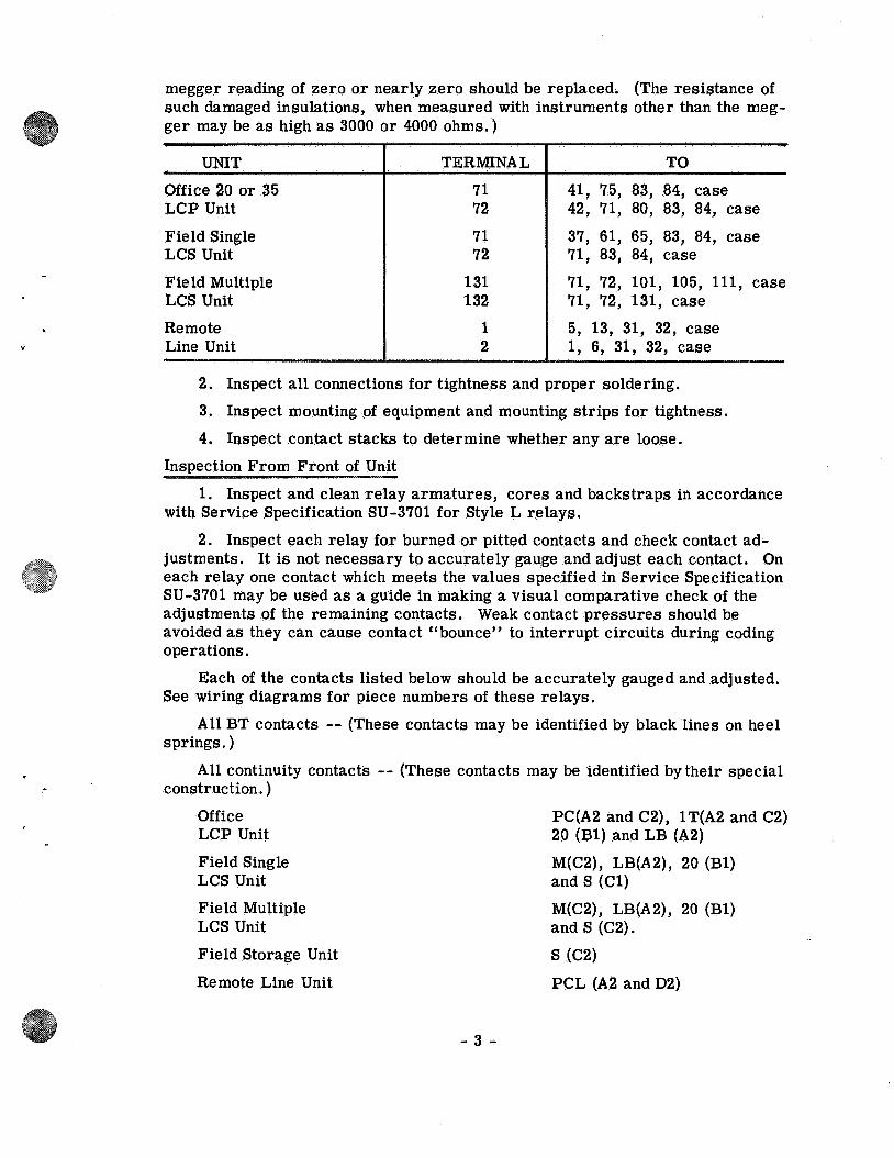
megger reading of zero or nearly zero should be replaced. (The resistance of such damaged insulations, when measured with instruments other than the megger may be as high as 3000 or 4000 ohms.)
UNIT TERMINAL TO
Office 20 or 35 71 41, 75, 83, 84, case LCP Unit 72 42, 71, 80, 83, 84, case
Field Single 71 37, 61, 65, 83, 84, case LCS Unit 72 71, 83, 84, case
Field Multiple 131 71, 72, 101, 105, 111, case LCS Unit 132 71, 72, 131, case
Remote 1 5, 13, 31, 32, case Line Unit 2 1, 6, 31, 32, case
2. Inspect all connections for tightness and proper soldering.
3. Inspect mounting of equipment and mounting strips for tightness.
4. Inspect contact stacks to determine whether any are loose.
Inspection From Front of Unit
1. Inspect and clean relay armatures, cores and backstraps in accordance with Service Specification SU-3701 for Style L relays.
2. Inspect each relay for burned or pitted contacts and check contact adjustments. It is not necessary to accurately gauge and adjust each contact. On each relay one contact which meets the values specified in Service Specification SU-3701 may be used as a guide in making a visual comparative check of the adjustments of the remaining contacts. Weak contact pressures should be avoided as they can cause contact "bounce" to interrupt circuits during coding operations.
Each of the contacts listed below should be accurately gauged and adjusted. See wiring diagrams for piece numbers of these relays.
All BT contacts -- (These contacts may be identified by black lines on heel springs.)
All continuity contacts -- (These contacts may be identified by their special construction.)
Office LCP Unit
Field Single LCS Unit
Field Multiple LCS Unit
Field Storage Unit
Remote Line Unit
- 3 -
PC(A2 and C2), 1 T(A2 and C2) 20 (Bl) and LB (A2)
M(C2), LB(A2), 20 (Bl) and S (Cl)
M(C2), LB(A2), 20 (Bl) and S (C2).
S (C2)
PCL (A2 and D2)

STYLE L RELAYS
Description
Style L-1 and L-3 relays used in the Type L-Form 520 Time Code Control System are direct current neutral relays. Style L-1 relays are equipped with a "round" armature and are ordinary acting. Style L-3 relays have a "square" armature and a double magnetic circuit and, therefore, are adaptable as slow release relays when shunted by a rectifier or resistor. These "square" armature relays are employed principally for code impulse timing. The coil resistances and contact combinations vary with requirements.
These Style L re lays are housed in groups in sheet metal cases which in some instances are plug-connected for convenience in changing out units. Individual relays, however, are not plug-connected. Inspection and adjustment work is performed on the relays while assembled in the units.
A relay in a unit may be identified by the individual nomenclature tag on the front of the relay armature, and the piece number stencilled under the tag and on the relay backstrap. These designations are also shown on the wiring diagram of the unit.
Calibration
Style L relays should be repaired, readjusted and recalibrated when necessary in accordance with Service Specification SU-3701, associating the particular relays by piece number. However, the timing of relays in wired units shall be made in accordance with discussions appearing later in this pamphlet.
STYLE KP MAGNETIC (POLAR) RELAYS
Description
Style KP relays are polar type direct current two position relays. These may be polar stick or polar biased type. The stick type remains without energy in its last operated position. The biased type functions similar to a neutral relay except that it will operate only on energy of normal polarity.
Style KP relays possess proper sensitivity for operation in the multiple type line circuit. The office line relay is the polar stick type, and has two normal and two reverse independent contacts. The field line relay and codestarting relay are the polar biased type, and have two normal and two reverse independent contacts. The field functional control relays and office machine traffic direction relays are the polar stick type, and have four normal and four reverse non-independent contacts.
All KP relays are individually housed in bakelite cases, with all operating parts fully enclosed and sealed. They have two coils which may be used either independently or in combination. The coil resistances vary with requirements. KP relays are individually plug-connected for convenient replacement. Combination of notches in the relay case and pins on the plug-rack prevent plugging an incorrect relay into a given position.
A KP relay may be identified by the individual nomenclature tag on the plug-rack, and the piece number stencilled on the back cover of the relay. These designations are also shown on the wiring diagram for the rack.
- 4 -
v

Calibration
Style KP relays should be repaired, readjusted and recalibrated when necessary in accordance with Service Specification SU-3623, associating the particular relays by piece number.
STYLE P-4 RELAYS
When Style P-4 relays are used in conjunction with the line circuit, they should be reshopped in accordance with Instruction Pamphlet U-5447.
AUTOMATIC TRAIN GRAPHS
CTC machines having automatic train graphs should have repairs, readjustments and calibrations of the graph mechanisms, pens and magnets made in accordance with Instruction Pamphlet U-5463. The mechanism is provided with plug-connectors to facilitate removal of the recorder from the machine for periodic servicing.
CODED CARRIER CONTROL EQUIPMENT
When coded carrier control equipment is used in conjunction with the Time Code Control System, repairs and readjustments should be made in accordance with Instruction Pamphlet U-5128.
- 5 -

DESCRIPTION OF APPARATUS AND SET-UP FOR MAKING
OPERATION, TIMING AND VOLTAGE TESTS ON COMPLETE CODING UNITS
TEST SETS
Complete circuits for the test sets used to test the Type L-Form 520 system units are shown on Dwg. D2586-Shs. 10 & 11 in the back of this pamphlet. These diagrams also show complete interconnections between test sets and standard C. T. C. units. Tabulated procedures for testing are also given. To operate a test set, both office and field coding units must be connected.
The Single Test Set (D2586-Sh. 10) connects to the office 35-station LCP unit and the field single LCS unit. The Multiple Test Set (D2586-Sh. 11) connects to the office 35-station LCP unit and the field multiple LCS unit and an additional field storage unit. The office 20-station LCP unit can be connected to either test set by interposing the office plug-converter (D2586-Sh. 10) between the office coding unit and the office plug-connectors. The field single LCS unit can be connected to the Multiple Test Set by interposing the field plug-converter (D2586-Sh. 10) between the field coding unit and the field plugconnectors.
CYCLE RECORDER
The Cycle Recorder is an instrument which provides a convenient means for measuring and recording short time intervals such as code impulses. A KP magnetic stick re lay follows the operations of any code line re lay, and its contacts operate two punch magnets which perforate a paper tape. The twopunch recorder gives a complete record of a whole code on one tape. Oddnumbered impulses are recorded by one punch magnet and even-numbered impulses by the other punch magnet, as shown in the illustration. When the tape record shifts from one impulse to the other, there should not be an overlap of more than one perforation. (This overlap will show when the shift occurs just as the a-c. timing wave reaches the point where both punch magnets will operate.) An overlap of more than one perforation, or loss of perforations, indicates that the cycle recorder needs adjustment. Adjustment of the cycle recorder is described in a later paragraph.
The tape record illustrated shows a correct tape. In reading a cycle recorder tape, count each perforation as 1/2 cycle. An overlap perforation on the end of the preceding code step should be disregarded in the count. The tape should be pulled through the recorder at a speed that will record approximately 10 cycles per inch.
EVEN PULSES
2 3 4 5 6 ......................... 2 v2 31/2 4V2 51/2 ....................
2 3 4 5 6 ..... ..... ..... ..... ..... 21/2 31/2 4 1/2 51/2 ......................
ODD PULSES
Typical Cycle Recorder Tape
- 6 -

To obtain the timing in terms of seconds, divide the recorder reading by the frequency (in cycles per second) of the power source.
When the only a-c. source available has a voltage of 220 volts, the recorder may be used by connecting a 1500 ohm resistor in series with terminal CX.
Cycle recorder tape is National Cash Register Tape-Size C, Ref. 2, Plate T-575, or it may be bought at any National Cash Register Supply Store.
Adjustment of Cycle Recorder
If, after continued use, the punches get out of adjustment, they may be readjusted as follows: Punches should line up with the holes in the brass plate and be set to punch holes approximately 1/16" apart. With paper tension plate removed and upper punch against the spring plate, bend the stop until the bottom point is just even with the top face of the brass plate. Now with lower punch against the bottom stop, bend the stop until the opening between the top point and the brass plate is just the thickness of the cycle recorder paper. With the tension plate and a piece of paper in place, the top spring should just touch, but not press on the paper with the armature down. With the armature up, the bottom punch should just touch the paper in the same manner. For more detailed adjustment of the double punch recorder see Service Specification SU-3688.
Cycle Recorder Connections
C.TC MACHINE
OFFICE 20-35
FIELD SINGLE
11011.A-C. {
NIG --84--84--72
CYCLE RECORDER r-------------, I I I I I ____... -I I I 1010 I
1070
I I -,
63--63--65--,o,s--t---l 8 n I ~ I OFF L-------~__J
PAPER
Figure 1 . . . Cycle Recorder Connections to Code Units
Figure 1 shows cycle recorder connections for measuring the timing of units either in the multiple code line installation or in the test set. The right-hand punches are for odd-numbered pulses and the left-hand punches are for evennumbered pulses.
Some cycle recorders are equipped with a cable and plug which can be inserted into a socket mounted on the terminal board in a C. T. C. machine or on the test set panel. This establishes proper connections quickly. An adapter socket equipped with clip-leads adapts this recorder for field use without need f.or removing the cable wiring.
- 7 -

TEST RELAY
SWITCH
c-Q--
}110V.
A.C.
Figure 2 ... Measuring Relay Pick-up and Release Time.
Figure 2 shows cycle recorder connections for measuring timing of an individual relay. Since the time constant of the relay depends on its circuit as a whole, the test circuit must be similar to the circuit in which the relay is to be used, without added shunt or series resistance. (For instance, a certain relay releasing in 3 cycles, when shunted by a voltmeter released in 12 cycles.)
To measure pick-up time, close switch and read right-hand punch until the left-hand punch starts.
To measure release time, open switch and read left-hand punch from the time the right-hand punch stops.
r----------., I I I E3 I I I I I I _j I I I I .... I 1------------l
TEST RELAY 4lic....
c-CJ---::4'. """'--< B SWITCH
}110V.
----+I- A.C.
I
I I I I I © I I
CYCLE RECORDE~ e e 9 ! L_ ------r £.P°.;_J
PAPER~
Figure 3 ... Measuring Contact Open-Transfer Time
Figure 3 shows cycle recorder connections for measuring open-transfer time of an individual re lay.
- 8 -

To measure open-transfer time on pick-up, close switch Sand read righthand punch while the left-hand punch is not punching.
To measure open-transfer time on release, open switch Sand read righthand punch while the left-hand punch is not punching.
- 9 -

TIMING OF UNIT CODE STEPS
Short Impulses
A short odd-numbered code step (line relay contacts counterclockwise) is timed by the pick-up of a counting relay, release of 1 T and the pickup of R.
A short even-numbered code step (line relay contacts clockwise) is timed by the pickup of a counting relay, release of 2T, pickup of 1 T and the release of R.
Speed of Counting Chain
When all counting chain relays are properly adjusted and cleaned, they will follow a speed of about 20 pulses a second at normal voltage. If the unit operates properly at the various voltages as outlined under Voltage Test, page 20, ample margin is provided in the counting chain.
Long Impulses
A long odd-numbered code step is timed by the release of lL, LP and lT, and the pickup of R.
A long even-numbered code step is timed by the release of 2L, LP and 2T, the pickup of 1 T and the release of R.
In timing a unit, it is an aid to remember that lT and lL (being odd-numbered) enter into the determination of the length of all odd-numbered code steps, while 2T and 2L (being even-numbered) enter into the determination of the length of all even-numbered code steps. LP adds time to both the oddnumbered and even-numbered long code steps of the unit transmitting to provide necessary operating margins between the transmitter and receiver units.
Conditions for Checking Timing of Units
When timing checks and adjustments are made with the coding unit operating in the test set, the timing of the various code steps shall be measured with the cycle recorder while the unit is transmitting codes at an operating voltage of 16-18 volts d-c. and under nominal temperature conditions (70°F). Capacity of battery and size of leads should be large enough· to minimize drop in terminal voltage. The procedures outlined on drawing 02586-Sh. 10 and 11 should be followed to operate the unit in the test set, code steps being made short or long as required. The cycle recorder should be plugged into the test set pane 1 and the timing switch placed in the OR positiqn.
Timing tables I and II, pages 13 and 15, show the correct timing values based on power supply frequencies of 60 and 100 cycles per second respectively. (Where a-c. frequency is other than 60 or 100 cycles, multiply values in Table II by a-c. frequency being used and divide by 100).
The timing of the various code steps is controlled by the release timing of several relays operating in the wired unit with their natural shunts. When relay adjustments are required to change timing, these adjustments should be made in accordance with Service Specification SU-3701. When necessary to retime a relay by bending the armature to change the airgap, care should be taken to insure that --
- 10 -

a. Armature stroke is within specified limits.
b. Armature strikes backstrap evenly on all four corners.
c. Armature is parallel to pole face and not touching it.
d. Armature insulation plate is parallel to backstrap.
e. Armature moves freely with stop in place.
f. Armature operates all contacts properly.
g. The electrical calibration remains within specified limits.
Order of Making Timing Measurements And Adjustments in Test Shop
With the coding unit to be checked operating in the test set at proper voltage, the timing measurements taken of the various code steps transmitted by that unit and the relays requiring adjustments to produce proper timing, shall be made in the order outlined below to the values given in Table I or Il -(The count numbers refer to the counts listed in Tables I and II).
1. Send codes having maximum number of short impulses and check the timing of the short odd-numbered code steps (count 1). If necessary to correct the timing, adjust relay 1 T.
2. Send codes having maximum number of short impulses and check the timing of the short even-numbered code steps (count 1) .. If necessary to correct the timing, adjust relay 2T.
3. Insert a piece of paper to insulate front contacts A3 and C3 of relay LP, thus eliminating relay LP from the timing of long impulses. Then send codes having maximum number of long impulses and check the timing of the abbreviated long code steps 9, 11, 13, 15, 17 and 19 (count 2). If necessary to correct" timing, readjust relay lL.
4. With relay LP still eliminated, send codes having maximum number of long impulses and check the timing of the abbreviated long code steps 10, 12, 14, 16 and 18 (count 2). If necessary to correct timing, readjust relay 2L.
5. Remove the insulations from contacts of relay LP. Send codes having maximum number of long impulses and check the timing of long code steps 9 to 19 (count 3). If necessary to correct timing, readjust relay LP.
6. Send codes having a maximum number of long impulses. Adjust relay LB so that it does not release when the unit is transmitting on 12-13 volts. Return to operation at 16-18 volts.
7. In the field LCS unit insulate front contact C3 of relay SSR, thus eliminating relays SSR and SS from the timing. No contact insulation is necessary in the office LCP unit. Send consecutive codes by operating codestarting switch upward, then check the timing of the extra long step 20 between codes (counts 4A or 4B). If necessary to correct timing, readjust relay LBP. This time measurement is slightly less for the office LCP unit (count 4A) than for the field LCS unit (count 4B), thus giving control codes preference over indication codes.
- 11 -

8. In the field LCS unit remove SSR contact C3 insulation, then insulate back contact A6 of relay LBPS. Send consecutive indication codes and check the timing of the extra long step 20 between codes (count 5). If necessary to correct timing, readjust relay SS.
When checking an extra field storage unit, use a correctly timed LCS unit with back contact A6 of LBPS insulated, and set Unit switch to GA-S position. Send consecutive indication codes and check the timing of the extra long step 20 between codes (count 5). If necessary to correct timing, readjust relay SS in the storage unit.
9. In the field LCS unit remove LBPS contact A6 insulation and send consecutive indication codes. Check the timing of the extra long step 20 between codes (count 6). If necessary to correct timing, readjust relay SSR.
10. In the office LCP unit, insulate front contact A5 of counting chain relay 8 and send a control code. The code will drop out on step 9 and reset on step 10. Check the drop-out timing of code step 9 (count 7). If necessary to correct timing, readjust relay M. When checking the 35-station office LCP unit, this same type of code will be produced by operation of the Recall button. Remove relay 8 contact A5 insulation after this test.
11. Change the Timing switch to the PCPP position. Have the office LCP unit receive an indication code and check the release timing of relays PCP and PCPP in cascade during code step 20 (count 8). If necessary to correct timing, readjust relay PCPP. Return Timing switch to OR position after this test.
NOTE - Operations 8 and 9 are omitted when checking the office unit. Operations 10 and 11 are omitted when checking the field units.
The following timing measurements should be checked after the unit has been adjusted to correct timing as outlined above. No adjustments are required when making these checks.
12. Send a code and check the timing of the first code step (counts 9A or 9B). If the timing is not within specified limits, check the calibrations of relays lL, 2L, LP, LB, LBP, LBPS and E.
13. Send a code and check the timing of the long impulses that appear in code steps 2, 3, 4, 5, 6 and 7 (count 10). If the timing is not within specified limits, check the calibration of relays F, G, Sand SP.
14. Send a code containing a long eighth impulse and check the timing of code step 8. If the office 20-station unit is being used (Stations switch in position 20) the timing should be as listed for count llA. However, if the office 35-station unit is being used (Stations switch in position 35) the timing should be as listed for count llB.
15. The time between codes when consecutive short control codes are being sent can be obtained only on the regular installation when the CTC machine is wired for the purpose. The last step of short control codes may occur on code steps 8, 10, 12, 14, 16 or 18 depending on the wiring, and its timing should be as listed for count 12, which is the same time as the twentieth code step, count 4A. (When testing the 20-station office LCP unit, sending consecutive recall codes will produce an extra long code step 8 equal to count 12).
- 12 -

COUNT NO.
1
2
3
4A
4B
5
6
7
8
_TIMING TABLE I - Time Code Control System - Type L - Form 520 - D2586
Timing with Units Connected in Test Set - Timing in Cycles (60 cycles = 1 second}
Test Conditions - Local Battery 16-18V. while coding - Nominal Line Current - Temperature 70°F. Approx.
TIMING LIMITS OPERATION IN ADJUSTMENTS CODE STEPS Timing within Retime to TEST SET TO REQUIRED
these limits these limits OBTAIN TIMING TO OBTAIN requires no ad- when necessary. MEASUREMENTS TIMING
justments.
MIN. MAX. MIN. MAX.
2 to 19 - Shorts 5 7 5.5 6.5 Time Relays 1 T and 2T
9 to 19 - Longs (Without LP) 16 19 16. 5 18.5 Insulate LP Contacts Time Relays lL and 2L A3 and C3
9 to 19 - Longs (With LP) 21 25 22 24 Remove LP Contact Time Relay LP
20-Between Consecutive Control 62 67 63 65 Time Office LB and LB Codes
20-Between Consecutive Indication 64 69 65 67 Insulate SSR Contact Time Field LB and LBl Codes (Without SSR and SS) C3
20-Between Consecutive Indication 77 83 79 81 Remove SSR Contact Time Relay SS Codes (Without SSR but with SS) Insulation and Insulate
LBPS Back Contact A6
20-Between Consecutive Indication 97 103 99 101 Remove LBPS Contact Time Relay SSR Codes (With SSR and SS) Insulation
9-Drop-out of Control Code 59 64 60 62 Insulate Relay 8 Time Relay M Front Contact A5
Release Time of PCP Plus PCPP 18 24 20 22 Set Timing Switch Time Relay PCPP to PCPP Position and Receive an Indication Code
- 13 -
p

TIMING TABLE I - Time Code Control System - Type L - Form 520 - 02586 (Cont'd)
Timing with Units Connected in Test Set - Timing in Cycles (60 cycles = 1 second)
Test Conditions - Local Battery 16-18V. while coding - Nominal Line Current - Temperature 70°F. Approx.
COUNT TIMING LIMITS NO. CODE STEPS Timing within Retime to Operation in Adjustments
these limits these limits Test Set to Required requires no ad- when necessary Obtain Timing To Obtain
justments. Measurements Timing
MIN. MAX. MIN. MAX.
NO TIMING REQUIRED THESE VALUES ARE FOR REFERENCE WHEN VALUES ARE EX-ONLY CEEDED CHECK CAL-
IBRATION OF
9A 1 - Long - Control Code 30 35 lL, 2L, LP, LBP, LBPS, E.
9B 1 - Short - Indication Code 11 14 1L,2L,LP,LB,LBP,LBPS
10 2-3-4-5-6-7- Longs 23 28 F, G, S, SP.
11.A 8 - Long - When Used For Station 23 28 Selection
llB 8 - Long - When Used for Function 21 25 Selection
12 8-10-12-14-16-18 - Between Consecu- 62 67 tive Short Control Codes
Counts referred to mean actual values obtained from cycle recorder tapes of codes transmitted by unit under test.
- 14 -

COUNT NO.
1
2
3
4A
4B
5
6
7
8
TIMING TABLE II - Time Code Control System - Type L - Form 520 - D2586
Timing With Units Connected in Test Set - Timing in Cycles (100 cycles = 1 second)
Test Conditions - Local Battery 16-18V. while coding - Normal Line Current - Temperature 70°F. Approx.
TIMING LIMITS OPERATION IN ADJUSTMENTS CODE STEPS Timing within Retime to TEST SET TO REQUIRED
these limits these limits OBTAIN TIMING TO OBTAIN raquires no ad- when necessary. MEASUREMENTS TIMING
justments.
MIN. MAX. MIN. MAX.
2 to 19 - Shorts 8.5 11. 5 9 11 Time Relays 1 T and 2T
9 to 19 - Longs (Without LP) 27 32 28 31 Insulate LP Contacts Time Relays lL and 2L A3 and C3
9 to 19 - Longs (With LP) 35 42 37 40 Remove LP Contact Time Relay LP Insulations
20-Between Consecutive Con- 103 112 105 109 Time Office LB and LBP trol Codes
20-Between Consecutive In- 106 115 108 112 Insulate SSR Contact Time Field LB and LBP dication Codes (Without SSR C3 and SS)
20-Between Consecutive In- 128 138 131 135 Remove SSR Contact Time Relay SS dication Codes (Without SSR Insulation and Insulate but with SS) LBPS Back Contact A6
20-Between Consecutive In- 162 172 165 169 Remove LBPS Contact Time Relay SSR indication Codes (With SSR Insulation and SS)
9-Drop-out of Control Code 98 107 100 104 Insulate Relay 8 Front Time Relay M Contact A5
Release Time of PCP Plus 30 40 33 37 Set Timing Switch to Time Relay PCPP PCPP PCPP Position and Re-
ceive an Indication Code
- 15 -

COUNT NO.
9A
9B
10
llA
llB
12
TIMING TABLE II - Time Code Control System - Type L - Form 520 - 02586 (Cont'd)
Timing With Units Connected in Test Set - Timing in Cycles (100 cycles = 1 second)
Test Conditions - Local Battery 16-18V. while coding - Normal Line Current - Temperature 70°F. Approx.
CODE STEPS TIMING LIMITS TIMING LIMITS OPERATION IN ADJUSTMENTS Timing within Retime to TEST SET TO REQUIRED these limits these limits OBTAIN TIMING TO OBTAIN
requires no ad- when necessary. MEASUREMENTS TIMING justments.
MIN. MAX. MIN. MAX.
NO TIMING REQUIRED THESE VALUES ARE FOR REFERENCE ONLY When Values are Exceeded Check Calibration Of
1 - Long - Control Code 50 58 1L,2L,LP, LBP, LBPS, E.
1 - Short - Indication Code 18 23 lL, 2L, LP, LB, LBP, LBPS.
2-3-4-5-6-7-Longs 38 47 F, G, S, SP.
8 - Long - When Used For 38 47 Station Selection
8 - Long - When Used For 35 42 Function Selection
8-10-12-14-16-18 - Between 103 112 Consecutive Short Control Codes
Counts referred to mean actual values obtained from cycle recorder tapes of codes transmitted by unit under test.
- 16 -

APPROXIMATE RELEASE TIME OF SLOW RELEASE RELAYS
Approximate Approximate Relays Release Time (Secs.) Air Gap
60 Cyc./Sec. 100 Cyc./Sec. (Inches)
1 T (Office) 4 6.5 0.008
lT (Field) 4 6.5 0.015
2T 3 5 0.005
lL 12.5 21 0.006
2L (Office) 12.5 21 0.002
2L (Field) 12.5 21 0.006
LP 5.5 9 0.010
LB 15 25 0.006
LBP (Office) 9 15 0.006
LBP (Field) 12 20 0.006
SSR 22 37 0.005
SS 12 20 0.007
M (Office) 12 20 0.003
PCPP-MPCPL 19.5 32.5 0.003
lLL, 2LL, LBL, LBPL 16 26.5 0.003
- 17 -

When measuring the timing of units in the test set, the various counts given in Timing tables I and Il can be determined by taking the following cycle recorder tapes:
Tape No. 1 - Having maximum number of short impulses - count 1.
Tape No. 2 - Having maximum number of long impulses - count 2.
Tape No. 3 - Having maximum number of long impulses - counts 3, 9A,
9B, 10, llA and llB.
Tape No. 4 - Consecutive codes - count 4A or 4B.
Tape No. 5 - Consecutive codes - count 5.
Tape No. 6 - Consecutive codes - count 6.
Tape No. 7 - Drop-out code - count 7.
Tape No. 8 - Release of PCPP - count 8.
Tapes 1, 2, 3, 4, 7 and 8 are taken when testing an office LCP unit. Tapes 1, 2, 3, 4, 5 and 6 are taken when testing a field LCS unit. Only tape 5 need be taken when testing a field extra storage unit.
TIMING OF THERMAL CUTOUT RELAY IN A FIELD LCS UNIT
Timing Check Made in Test Set
After a field LCS unit has been properly timed as outlined by the preceding paragraphs, the timing of the thermal cutout relay CO shall be measured in the test set. CO has a steadily energized voltage-compensator element, and a normally de-energized operation-heater element.
First, remove the field line relay R from the test set and position the RPP switch downward, then energize the LCS unit at 16 to 18 volts and release relay ST by operating the starting switch. Let the unit remain at rest for at least 12 minutes before starting a measurement. This insures that the compensator is hot and the heater is cold. Next, operate the RPP switch upward and measure the length of time the M relay is picked up (which is the time required for CO to open its contact). If this time is from 110 to 130 seconds, no adjustment is required. However, if the timing is not within these limits, the CO should be adjusted so M remains picked up for a nominal time between 115 and 125 seconds. Adjustment should be made in accordance with the followi~g procedures outlined under Contact Spring Adjustment and Timing Adjustment.
After CO has been heated to obtain one time measurement, position switch RPP downward for at least another 12 minutes before placing RPP switch upward to start another time measurement. Always allow 12 minutes stabilizing time between each measurement.
Contact Spring Adjustment
To determine whether the contact spring members have become mis-adjusted, de-energize the LCS unit for at least 12 minutes to insure that both compensator and heater elements are cold. Then place a small magnetic shunt (such as soft iron or transformer steel, approximately 0. 010" thick) in the air
- 18 -

gap across the permanent magnet poles opposite the curved steel armature, both of which are attached to the extreme ends of the contact members (see Figure 4) . This shunt relieves the attraction between armature and magnet, and the contact tips should open between O. 022 and O. 028 inch. In making adjustment to obtain contact opening between these limits, apply a bending tool to the heavy member which supports the bimetal strip, applying it between the insulating blocks and the hole in the side of this member.
Never bend the bimetal strips. Remove the magnetic shunt and check to see that the silver contact tips meet squarely. Repeat the timing check outlined by the preceding discussion under Timing Check Made In Test Set.
BEND FOR CLEARANCE
SILVER CONTACT TIPS
COMPENSATOR ELEMENT
,-.__ __ CURVED STEEL
PERMANENT MAGNET ARMATURE
Figure 4 ... Snap Action Thermal Cutout Relay With Voltage Compensator
Timing Adjustment
If the operating time of CO is still not within the specified limits when the Contact Spring Adjustment conditions are correct, further timing adjustment can be made by changing the air gap between the permanent magnet and its armature. This adjustment can be made with the compensator element either hot or cold. Apply a small bending tool to the straight portion of the curved steel armature, holding the contact firmly so that the bimetal strip will not bend, and bend the armature toward or away from the magnet. (A very slight change in air gap makes an appreciable difference in timing.) To lengthen the time required to open the contact, decrease the air gap; to shorten the time, increase the air gap. Repeat the timing check outlined by the preceding discussion under Timing Check Made In Test Set. (IMPORTANT --- When correctly adjusted, the curved armature must not come in contact with the permanent magnet at any time during operation).
Operating Cycle (For Reference Only)
If the initial opening of the thermal cutout relay CO is within specified values, it will reclose its contact after each operation in 90 to 120 seconds, and will re-open its contact for successive operations in not less than 50 seconds, provided the ST relay remains released and RPP switch is left in its upward position.
- 19 -

TESTS OF CODING UNITS FOR OPERATION ON VARIABLE CffiCUITS
When the coding unit has been properly cleaned, adjusted and timed as outlined by the preceding discussions, the performance of the unit and all its integral circuits are checked by operating that unit in the test set and following the testing procedure tabulated on Drawing D2586-Sh. 10 or 11 at the end of this pamphlet.
TESTS OF UNITS ON VOLTAGE LIMITS
As an overall check to insure ample margins on the timing of the relays, operate the office unit on 13 volts and vary the voltage at the field unit from 13 to 24 volts and note that proper performance is obtained. Then operate the field unit on 13 volts and vary the voltage at the office unit from 13 to 24 volts and note results. Finally, apply 24 volts to both the office and field units and note results. Use station codes 246 and 357 for these tests. Relays M and LBP should not re lease during any code.
TESTING REMOTE LINE UNIT
The relays in the Remote Line unit are adjusted and calibrated as instructed in Service Specification SU-3701. The internal circuits are checked by operating relays to manually set up circuits for testing with a buzzer, voltmeter, test lamp or other suitable instrument, following the circuits shown on Drawing D2586-Sh. 7. The unit is not given an operating check in the test shop.
The timing of the relays in the unit is checked by making the connections shown in Figure 5, and applying 16-18 volts a-c. energy. The timing is measured with the cycle recorder, reading the odd-pulse perforations on the tape. Timing Tables m and IV, pages 22 & 23, show the correct values based on 60 and 100 cycle a-c. power supply. When setting up the circuits shown in Figure 5, a suitable two-pole snap switch is recommended which will produce simultaneous opening of both circuits. Timing measurements are obtained by following the procedure outlined below:
1. Connect wire A to terminal 11, wire B to terminal 12 and wire C to terminal 15, then close the switch to pick up lLL, 2LL, LBL, LBPL and MPCPL. Next, start the cycle recorder and then open the switch to measure the release time of lLL, as specified by Table m or IV (count 1). If necessary to correct timing, adjust relay lLL.
2. Connect wire A to terminal 12, wire B to terminal 11, leave wire C connected to terminal 15, then close the switch. Next, start the cycle recorder and open the switch to measure the release time of 2LL (count 2). If necessary to correct timing, adjust relay 2LL.
3. Leave wire A connected to terminal 12 and wire B to terminal 11, move wire C to terminal 16, then close the switch. Next, start the recorder and open the switch to measure the release time of 2LL plus LBL (count 3). If necessary to correct timing, adjust relay LBL.
4. Move wire C connection to terminal 17, and close the switch. Next, start the recorder and open the switch to measure the re lease time of 2LL plus LBPL (count 4). If necessary to correct timing, adjust relay LBPL.
- 20 -

5. Move wire C connection to terminal 13 and close the switch. Next, start the recorder and open the switch to measure the release time of 2LL plus MPCPL (count 5). If necessary to correct timing, adjust relay MPCPL.
6. Leave wires A and C disconnected and connect wire B to terminal 21. Closing the switch will pick up relay PCL. No timing measurement or adjustment of relay PCL is necessary.
,-1 20
NIG ..,...__.t---------------<32
I
816 .>--!-------------/: I •SNAP SWITCH AB } { ~ REMOTE I
- -------,,.:_y LINE UNIT I I '20 02586-SH.7 i ~ ~ I I
!_j ! ---@ I --@ --@
L_ _ _J
I
~ I
As;.{~ ----§
...J.....
Figure 5 . • • Connections for Timing Remote Line Unit
- 21 -

COUNT NO.
1
2
3
4
5
TIMING TABLE ill - Time Code Control System - Type L - Form 520 - D2586
Timing of Remote Line Unit - Timing in Cycles (60 cycles = 1 second)
Test Conditions - 16-18 Volts - Temperature 70°F. Approximately - Connections Per Figure 5
RELEASE TIME OF RELAYS
1LL
2LL
2LL + LBL
2LL + LBL + LBPL
2LL + MPCPL
TIMING LIMITS Timing within Retime to these limits these limits requires no when
adjustments. necessary.
MIN. MAX. MIN. MAX.
14 18 15 17
14 18 15 17
30 35 31 33
46 51 47 49
32 40 34 37
- 22 -
ADJUSTMENTS REQUIRED TO OBTAIN TIMING
Time Relay 1LL
Time Relay 2LL
Time Re lay LBL
Time Re lay LBPL
Time Re lay MPCPL

COUNT NO.
1
2
3
4
5
TIMING TABLE IV - Time Code Control System - Type L - Form 520 - 02586
Timing of Remote Line Unit - Timing In Cycles (100 cycles = 1 second)
Test Conditions - 16-18 Volts - Temperature 70°F. Approximately - Connections Per Figure 5
I
RELEASE TIME OF RELAYS
lLL
2LL
2LL + LBL
2LL + LBL + LBPL
2LL + MPCPL
TIMING LIMITS Timing within Retime to these limits these limits requires no when
adjustments. necessary.
MIN. MAX. MIN. MAX.
24 30 25 28
24 30 25 28
50 58 52 55
77 85 79 82
54 66 57 61
- 23 -
ADJUSTMENTS REQUffiED TO OBTAIN TIMING
Time Relay lLL
Time Relay 2LL
Time Re lay LBL
Time Relay LBPL
Time Re lay MPCPL

SPECIAL UNITS
Relays in the Field Pyramid unit, Office Auxiliary Line unit, and other similar special units, are adjusted and calibrated as instructed in Service Specification SU-3701 and SU-3623. Internal circuits are checked by operating relays to manually set up circuits for testing with a buzzer, voltmeter, test lamp or other suitable instrument, following the circuits on drawing D2586-Sh. 9 or other special drawings. The units are not given an operating check in the test shop. The relays require no timing measurements or timing adjustments.
- 24 -

PART ill
FIELD MAINTENANCE TESTS
GENERAL
At the time a unit is replaced, the test man should have a complete operating check made of the new unit to assure that it is functioning properly
The field tests outlined in the following paragraphs should be made periodically (perhaps quarterly) on units in service to anticipate trouble before delays are actually caused. It is also recommended that the maintainer make a periodic visual inspection of relay contacts and operation. Units and line relays which do not meet specified field inspection limits should be reshopped in accordance with Part II of this pamphlet.
TIMING OF UNITS IN SERVICE
The timing of any unit in service at any location may be checked from the office by sending control codes and by recalling indication codes, then obtaining timing tapes with the cycle recorder and its associated relays connected to the C. T. C. machine. These tapes should be checked against the values shown in Tables I and II, Pages 13 and 15, in the columns under heading "Timing Within These Limits Require No Adjustments." A suggested form for conveniently recording timing data is included at the back of this pamphlet. It is best to obtain these tapes when the outdoor temperature is between 30°F and 90°F. In extreme weather conditions the timing of the code steps may differ by two to four per cent because of the effects of temperature on the equipment.
The timing values covered by counts 1, 3, 9A, 9B, 10, llA and llB in the tables may be obtained from the tapes of individual control codes and indication codes recalled from the unit being checked. The timing values shown as counts 4A, 4B, 6 and 11 are obtained by means of consecutive codes as follows:
The extra long impulse at the end of one recall control code being followed immediately by a second recall control code provides counts 4A and 12 for the office unit. The extra long impulse at the end of a recall control code followed immediately by an indication code provides count 4B for the indicating field unit. (The extra long impulse between two successive indication codes from two different stations will be approximately 5 per cent longer than count 4B). To obtain count 6, first send a recall control code, then while the indication code from that station is being received, store a second recall control code to the same station. The extra long impulse at the end of the second recall control code followed immediately by a second indication from that station provides count 6 for the indicating field unit.
Count 7 may be obtained on only the 35-station office coding unit by sending a recall control code to any station. Counts 2, 5, 7 and 8 are obtainable only when checking with the test set and having the unit unsealed.
SERVICE TEST FOR THERMAL CUTOUT RELAY
If desired, the timing of the thermal cutout re lay CO in the LCS unit may be checked at a field location under service conditions, provided it is permissible for the station to be made inoperative during the period of the test.
- 25 -

To check the CO timing under service conditions, first remove the wires from terminals 61 and 71 of the single LCS unit, or from terminals 101 and 131 of the multiple LCS unit, then let the unit remain at rest for about 12 minutes. Next, remove the wire from terminal 20 to re lease ST, which will pick up M to start heating CO. Measure the length of time that relay M remains picked up, which should be 105 to 135 seconds when the voltage applied to the unit is 16 to 18 volts. The operating time is slightly longer at lower voltages and slightly shorter at higher voltages.
After the test, reconnect all wires to their proper terminals, making the connection to terminal 71 or 131 last.
CAUTION - If the installation is equipped with Field Station Disconnect equipment, relays RP and RPP will release during this test. Therefore, connect a jumper between terminals 63 and 64 of the single LCS unit or between terminals 103 and 104 of the multiple LCS unit before starting this test, thereby holding up re lays RP and RPP during the test period. If RP and RPP become released at the conclusion of the test, they must be picked up by having the operator send a recall control code to this station.
STYLE KP MAGNETIC (POLAR) LINE RELAYS
Once a year the calibration values of the Style KP line relays should be measured. These values should be checked against those specified in Service Specification SU-3623.
PLUG CONNECTOR TESTS
Plug connectors are used on all of the code equipment where interchangeability is desired. When removing a plug connector from a unit, a small wooden pry about 1/2" x 1/2" x 12" will be found handy.
To inspect a plug connector, take an individual socket or female member (or special test socket shown on plate T-575) and slide it over each wire spring in turn. If the spring does not seem to make good contact, insert the bit of a screw driver into the loop of the spring and twist first one way and then the other. This will increase the tension. The screw driver should be inserted in the two loops, and not between the two loops in such a way that they become separated. A properly adjusted connector should require a force of not less than 1 lb. or more than 2 lbs. to remove it from the socket. If a connector is found to be faulty in any way, or if one side of the spring loop is broken off, it should be replaced with a new one.
When placing a plug connector back on the unit, care should be taken to see that all of the wire springs are properly started into the sockets before the plug-connector is pressed into place.
To check KP relay plug connectors, insert a metal strip 1/32" x 1/ 4" x 3" into each spring slot and note that the plug connector spring bears against the insert with reasonable pressure, requiring 1 to 2 lb. pull to remove insert. A faulty plug connector should be replaced.
LINE cmcUIT TESTS
Since the line circuit is the "highway" over which all code traffic communicates, periodic checks should be made of this line circuit to anticipate
- 26 -

possible disturbances. The following discussion suggests a number of recommended line tests.
A. D-C. Line Section - Grounds, Leakage, Bleeding
1. Lines Ll and L2 should be, checked for possible grounds using a megger or other suitable instrument. Some lightning arresters may have to be disconnected when making these tests. On some installations the mid-tap of the code line battery is connected to ground. This should be opened before making ground tests. Dirty code line batteries may show low resistance to ground. Batteries should be kept clean. A noisy telephone generally indicates existence of a ground on one line.
2. The resistance between lines Ll and L2 should be checked for excessive leakage, using an ohmmeter or other suitable instrument. The resistance should first be checked when the line is known to be in good condition, and this figure used to compare with later resistance readings taken to determine whether excessive line leakage is developing. Comparative readings should be taken under similar weather conditions.
3. The line bleeder circuit should be checked at the office or remote line location. To do this, disconnect lines Ll and L2 and connect an ohmmeter at the line terminals of the office or remote line units. At the office, pick up relay 1 T by applying battery to coding unit terminal 61, then check that the bleeder circuit resistance is what the line circuit plan calls for. At the remote line location, disconnect relay C from the Carrier unit and apply local battery to pick up relay C, or disconnect relay CP from the D-C. Repeater line to release relay CP. Then check the bleeder circuit resistance.
B. Coded Carrier Control
Line circuit readings should be taken periodically of the Coded Carrier Control equipment. The procedure for making these checks is dis
. cussed in Instruction Pamphlet U-5128.
C. Other Communication Facilities
Line circuits which have other communication facilities superposed, such as simplex, telephone, telegraph, selectors, facsimile, various carriers, etc., generally are provided with special instructions which specify recommended periodic tests.
D. Line Fault Determination
A broken or shorted line circuit affects the operation of the time code control system in a similar way; i.e., the near stations may be operative while the far stations may be inoperative. If the normal line current is known, line current less than normal indicates a broken line, while line current greater than normal indicates a shorted line.
A line break will be located just beyond the last station which can be controlled. The location of a line shunt can be determined by first disconnecting the line battery at the office or remote line station, then obtaining simultaneous line resistance readings with an ohmmeter at the near end and at the far end of the line section, referring to a pre-established curve diagram as illustrated by Figure 6. This curve diagram can be obtained beforehand by artificially producing shunts of various resistances (one at a time) at each field
- 27 -

station and measuring line resistance from each line end, then plotting these readings as a family of curves. Each curve diagram is different for each line section of every C. T. C. installation.
Making a line resistance check when no fault exists, the reading from the near end will be equal to value X and the reading from the far end will be equal to value Y, Figure 6. Assuming a line shunt occurs, as an example, suppose the near end reading is equal to XS and the far end reading is equal to YS. Referring to the curve, Figure 6, the projected lines indicate that a shunt of less than 200 ohms exists at a point just beyond station B toward station C.
0 z w a: ~ ::ii: 0 a: LL
w (.)
NO SHUNT y ------------------------
z YS ~ (/}
iii w a:
XS x RESISTANCE FROM OFFICE OR REMOTE LINE STATION
Figure 6 . . • Line Shunt Fault Determination Curves
- 28 -

PART IV
INSPECTION PROCEDURE FOR CONTROL CABINET
Office Storage Units
The relays in the Office Storage Units and KP racks should be given the same inspection as the relays in the coding units. This includes mechanical inspection, contact adjustment, and electrical calibration.
The hinges of the units and racks have removable pins so the units can be lifted out of the machine to a more convenient working position. A storage unit can be opened by breaking a wire seal, loosening two screws and swinging open the glass door. The door can be lifted off its hinges when desired.
In each storage unit there is a circuit disconnect device associated with each row of relays, mounted on the center post. Its purpose is to open all energy circuits to its row of relays, permitting the relays to be reconditioned with reasonable freedom and without disturbing the operation of the remainder of the machine. Each device handles six circuits. Normally the tips of each circuit are soldered together.
When work is to be performed, first all levers in the associated panel should be blocked in their center positions, pushbutton and toggle switch controls opened, and pushturn levers and starting button blocked to prevent operation. Next, all six circuits of the disconnect are unsoldered and the tips separated by inserting insulation plates (hung inside the glass door frame). Caution should still be exercised when using contact tools to avoid touching adjacent contacts while coding is in progress. The circuits can be temporarily closed by merely removing the insulations. When work has been completed, the circuits should be resoldered.
Levers and Pushbuttons
Contacts on levers and pushbuttons should have approximately the same adjustments as contacts on relays, except that the openings should be as shown be low, Figure 7.
CONTACT ADJUSTMENTS Standard Levers and Pushbuttons
FULL· STROKE POSITION
,025" MIN,
RELEASED POSITION
~ .ooo'MIN.
Ll ~:e: ::~s~f i .oos"MIN,
MID - POSITION
Push-Turn Levers
i~:)~st .0"40" MIN,
FULL• STROKE POSITION
RELEASED POSITION
MIO - POSITION
*NOTE: Contacts identified by a horizontal black line on heel spring loop to be adjusted to approximately 0.010" overlap.
Figure 7 ... Contact Adjustments
- 29 -

Cabinet Sections
Inter-section circuit couplers are provided to join the cable wiring between machine sections. Each coupler handles 40 circuits. Normally, the tips of each circuit are soldered together. A circuit can be opened by unsoldering the tips and inserting an insulator between them.
The lower front panel of each machine section is removable to facilitate working on the back of the terminal boards and the wire chase.
- 30 -

PARTV
GENERAL INFORMATION
The type L relay contact stacks are numbered A-B-C-D-E-F from left to right facing front of relay, which is the armature end. If a space for a stack is left vacant, the space is lettered as if the stack were present. Contact spring members are numbered 1-2-3-4-5-6-7 from top to bottom, only the members appearing in the stack being counted. Coil connectors are counted as a contact member, unless they are in the same space with the contact.
In soldering connections, wireman faces rear of the relay, so that his lettering is from right to left with A stack at the right, No. 1 being top member of each stack.
Relay Racks: The relay spaces of each strip are numbered from left to right, facing front, or relay armature end of the rack or control unit. Relay mounting strips are lettered A-B-C-D-E-F from top to bottom.
Wiring diagrams show the rear of the relay rack, control unit, or control panel, hence the wiring diagrams should be read from right to left with No. 1 space at the right.
Relay as shown Contact Arrangement Relay as shown on Wiring Diagram - Wired Accord-
on Circuit Plan Rear View of Relay ing to Color Code
r c B A c1• Al** Bk.
~ ~ C2 Bl A2 Bu.S. Bu .. -~ C3 B2 A3 o.w. R.S.
~ C4 B3 A4 s.w. ~ ~ C5 B4 A5 ~· _!h_ __Q,_
~ C6 B5 A6 o.s. _!:_... ~
*Coll Common ••coil Control
Figure 8 • . . Style L Relay Contact Numbering and Wiring
On the circuit diagrams, only the heel contact members are numbered and may therefore be identified on the wiring diagrams by their positions as shown in the above example, Figure 8. A color code scheme is usually used for wiring, and both solid and flexible wire are used. Flexible wire is identified on the wiring diagrams by a letter F after the color. On any one relay no two circuits have the same color of wire.
KP polar relays have their contacts numbered as shown below, Figure 9. On those KP relays which have independent contacts, 1 and 3 are normal contacts while 2 and 4 are reverse contacts.
- 31 -

IH--1-....-...
IA-· IP-t-f-.......
+I--+-+-"'-.
4P--ll-l-..... ~
4N-
4R-'...&.-'
KP RELAY
r--r--r--2R
,r -2N
---t-i--2P _.. ___ ,
CONTACT NUMBERING
VIEWED FROM rRONT
KP RELAY AS SHOWN ON CIRCUIT PLAN
+l=E3=-1 +2 -2
,--IP
IN---,.,.__IR> STICK
ZP SYMBOL
2N--r=.2R
BIASED
r--3P
3N__.,.. > SYMBOL
r--4P , .. ,.__4R
Figure 9 • • . KP Relay Contact Numbering Scheme
Contacts on levers and pushbuttons in the control machine are numbered in the same manner as the contacts of style L relays.
- 32 -

FIELD SINGLE LCS UNIT CODE SETTING CONNECTIONS
STATION CONNECT CONNECT CONNECT CONNECT CONNECT CONNECT CONNECT CODE POST 38 POST 39 POST 40 POST 22 POST 23 POST 24 POST 21
NUMBER TO POST TO POST TO POST TO POST TO POST TO POST TO POSTS
*234 42 43 44 2 3 4 5-6-7-8* *235 42 43 45 2 3 5 4-6-7-8* *236 42 43 46 2 3 6 4-5-7-8* *237 42 43 47 2 3 7 4-5-6-8* 238 42 43 48 2 3 8 4-5-6-7
*245 42 44 45 2 4 5 3-6-7-8* *246 42 44 46 2 4 6 3-5-7-8* *247 42 44 47 2 4 7 3-5-6-8* 248 42 44 48 2 4 8 3-5-6-7
*256 42 45 46 2 5 6 3-4-7-8* *257 42 45 47 2 5 7 3-4-6-8* 258 42 45 48 2 5 8 3-4-6-7
*267 42 46 47 2 6 7 3-4-5-8* 268 42 46 48 2 6 8 3-4-5-7 278 42 47 48 2 7 8 3-4-5-6
*345 43 44 45 3 4 5 2-6-7-8* *346 43 44 46 3 4 6 2-5-7-8* *347 43 44 47 3 4 7 2-5-6-8*
348 43 44 48 3 4 8 2-5-6-7 *356 43 45 46 3 5 6 2-4-7-8* *357 43 45 47 3 5 7 2-4-6-8*
358 43 45 48 3 5 8 2-4-6-7 *367 43 46 47 3 6 7 2-4-5-8*
368 43 46 48 3 6 8 2-4-5-7 378 43 47 48 3 7 8 2-4-5-6
*456 44 45 46 4 5 6 2-3-7-8* *457 44 45 47 4 5 7 2-3-6-8* 458 44 45 48 4 5 8 2-3-6-7
*467 44 46 47 4 6 7 2-3-5-8* 468 44 46 48 4 6 8 2-3-5-7 478 44 47 48 4 7 8 2-3-5-6
*567 45 46 47 5 6 7 2-3-4-8* 568 45 46 48 5 6 8 2-3-4-7 578 45 47 48 5 7 8 2-3-4-6 678 46 47 48 6 7 8 2-3-4-5
NOTE - When 35-Station Office LCP unit is used, code-setting connections are made as tabulated above. When 20-Station Office LCP unit is used, code-setting connections are made for only those station code numbers marked(*), and all connections from Post 21 to Post 8 are omitted,
- 33 -

FIELD MULTIPLE LCS UNIT CODE-SETTING CONNECTIONS
CONNECTIONS FOR GROUP A ADDITIONAL CONNECTIONS FOR GROUP B
Station Connect Connect Connect Connect Connect Connect Connect Connect Connect Connect Connect Connect Code Post 118 Post 119 Post 40 Post 88 Post 89 Post 24 Post 81 Post 120 Post 40 Post 90 Post 24 Post 81
Number To Post To Post To Post To Post To Post To Post To Posts To Post To Post To Post To Post To Posts
*234 112 113 121 82 83 91 92-93-94-95* *235 112 113 122 82 83 92 91-93-94-95* *236 112 113 123 82 83 93 91-92-94-95* *237 112 113 124 82 83 94 91-92-93-95* 238 112 113 125 82 83 95 91-92-93-94
*245 112 114 122 82 84 92 83-93-94-95* 114 126 84 96 97-98-99* *246 112 114 123 82 84 93 83-92-94-95* 114 127 84 97 96-98-99* *247 112 114 124 82 84 94 83-92-93-95* 114 128 84 98 96-97-99* 248 112 114 125 82 84 95 83-92-93-94 114 129 84 99 96-97-98
*256 112 115 123 82 85 93 83-84-94-95* 115 127 85 97 98-99* *257 112 115 124 82 85 94 83-84-93-95* 115 128 85 98 97-99* 258 112 115 125 82 85 95 83-84-93-94 115 129 85 99 97-98
*267 112 116 124 82 86 94 83-84-85-95* 116 128 86 98 99* 268 112 116 125 82 86 95 83-84-85-94 116 129 86 99 98 278 112 117 125 82 87 95 83-84-85-86 117 129 87 99
*345 113 114 122 83 84 92 82-93-94-95* *346 113 114" 123 83 84 93 82-92-94-95* *347 113 114 124 83 84 94 82-92-93-95* 348 113 114 125 83 84 95 82-92-93-94
*356 113 115 123 83 85 93 82-84-94-95* 115 127 85 97 98-99* *357 113 115 124 83 85 94 82-84-93-95* 115 128 85 98 97-99* 358 113 115 125 83 85 95 82-84-93-94 115 129 85 99 97-98
*367 113 116 124 83 86 94 82-84-85-95* 116 128 86 98 99* 368 113 116 125 83 86 95 82-84-85-94 116 129 86 99 98 378 113 117 125 83 87 95 82-84-85-86 117 129 87 99
*456 114 115 123 84 85 93 82-83-94-95* *457 114 115 124 84 85 94 82-83-93-95* 458 114 115 125 84 85 95 82-83-93-94
*467 114 116 124 84 86 94 82-83-85-95* I 116 128 86 98 99* 468 114 116 125 84 86 95 82-83-85-94 116 129 86 99 98 478 114 117 125 84 87 95 82-83-85-86 117 129 87 99
*567 115 116 124 85 86 94 82-83-84-95* 568 115 116 125 85 86 95 82-83-84-94 578 115 117 125 85 87 95 82-83-84-86 I 117 129 87 99 678 116 117 125 86 87 95 82-83-84-85
- 34 -

FIELD MULTIPLE LCS UNIT CODE-SETTING CONNECTIONS (Continued)
NOTE - When 35-Station Office LCP unit is used, code setting connections
are made as tabulated above.
When 20-Station Office LCP unit is used, code setting connections are
made as listed for only those station code numbers marked *, and all
connections from Post 81 to Posts 95 and 99 are omitted.
When Group B connections are made and connection is specified from
Post 90 to 84, 85, 86 or 87, then corresponding connection from Post
81 to 84, 85, 86 or 87 is omitted.
1 II n
OFFICE FIELD FIELD - TEST PANEL -LCP UNIT LCS UNIT S. UNIT
Figure 10 ... Multiple Type Test Set, Block Diagram
- 35 -

PIECE REF.
UN231678 c
2
UJ39826 3
UJ39864 4
UM164375 5
UM273829 7
UM164393 8
UJ39069 9
10
11
lla
UM106099 12
UM177803 13
UM172481 14
UJ62103 15
UJ39892 16
17
UM106100 18
UM243028 19
UM244733 20
U0245029 20a
U0255604 20b
UM244732 21
PLATE T-575
UNION SWITCH & SIGNAL DIVISION OF WESTINGHOUSE AIR BRAKE COMPANY
CYCLE RECORDER, TOOLS AND SUPPLIES FOR MAINTENANCE
Order by Plate, Piece, Reference and Abbreviated Description Given in Heavy Face Type Only
DESCRIPTION
DOUBLE PUNCH CYCLE RECORDER (When ordering state installation for which required) (Used with 16 Step 506 Time Code Systems) .•.•.
ROLL SIZE "C" PAPER FOR CYCLE RECORDER (10 per package)
PLIERS FOR REMOVING LAMP CAPS
OFFSET SCREW DRIVER for removing R&lay Armatures
BENDER (OFFSET) for Contact Springs .. , ••.••••.••..•••.••
SWEDGE AND TWISTING TOOL for Adjusting Relay Armatures .• , . ,
ANVIL for Adjusting Relay Armatures •••••.••.•• , .••••••..•
3/8" ELECTRIC SOLDERING moN WITH STAND
NO. 22 B. & S, GAUGE SOLID COPPER WIRE in color code for wiring control machine and control units (Orders should specify quantity and color desired).
NO. 20 B. & S. GAUGE FLEXIBLE COPPER WIRE in color code for wiring control machine and control units (Orders should specify quantity and color desired),
NO. 22 B. & S. GAUGE FLEXIBLE COPPER WIRE in color code for wiring control machine and control units (Orders should specify quantity and color desired).
PUNCH (Used with Eyelet Rivets to attach Armature Bakelite to Relay Armatures (Not shown) ••••.•••••.....••••.••.•..•..•.•
TOOL for removing Lamps .••..••...••.•.••.•••.•••.•.•
BENDER (STRAIGHT) for Contact Springs •.•••••••....•.•..•
GRAM GAUGE W. E. 68B for measuring contact pressures (Not shown)
BURNISHING TOOL W. E. 265C for cleaning contacts (Not shown)
RESIN CORE SOLDER for making soldered connections (Do not use acid core or acid soldering paste or fluid). (Not shown)
ANVIL (Used with eyelet Rivets to attach Armature Bakelite to Relay Armatures) (Not Shown) •..•.•.•......••••••••••.•••.•••
SOCKET for adjusting Spring Tension of C. T. C. type plug Connectors
PUNCH. Used with Tubular Rivets to attach Armature Bakelite to Relay Armatures ••.••••.•..•.•••.•.•.••.•.•.•.•.••.•
PUNCH AND ANVIL SET (Includes 1-20 and 1-21) .•...•....•.•.
REPAm SET FOR RELAY ARMATURES (Includes 1-7, 1-8, and 1-20)
ANVIL. Used with Tubular Rivets to attach Armature Bakelite to Relay Armatures ••.•••••••.•••.•..•.••.•.•.•.•..•.••
7/8/57
DWG. REF.
C-9299-4
A-2586-15
A-2586-95
A-2586-78
A-2586-34
A-2586-21
A-2586-14
A-2586-34
A-2586-60
A-2586-72
A-2586-72
A-2586-72
A-2586-72

PLATE T-575 -(CONTINUED)
UNION SWITCH & SIGNAL DIVISION OF WESTINGHOUSE AIR BRAKE COMPANY
PJECE REF. DESCRIPTION OWG. REF.
23 6" LONG-NOSE PLIERS (Not shown)
24 5" DIAGONAL CUTTING PLIERS (Not shown)
25 3" SCREW DRIVER (Not shown)
UN259590 26 KEY AND CLAMP for compressing Spring on Push Turn Lever ••••• A-2586-82
UM282051 29 BENDER (Right Hand) for Contact Strips • . • • . . • • . • . • . • • • • • • • A-2586-106
UM262634 30 BENDER for Thermal Cutout •••••.•.••.•.•••••••••.••••• A-2586-84
UM243059 31 BENDER for KN and KP Relays .•.••••••••••••.•..•••.•.• A-2586-68
UN320728 32 SPRING TESTER for LP-53, LP-58 and LP-70 Relay Bases •••.•.• A-2586-39
UN243000 33 ARMATURE POSITIONING GAUGE for Biased KP Relay (2 Required). A-2586-65
UN243001 34 ARMATURE POSITIONING GAUGE for Stick KP Relay with 4 Transfer Contacts (2 Required) . . • . • • . • • • • . • • • • . . . • • • • • • • . • • • • • • A-2586-65
UN243002 35 ARMATURE POSITIONING GAUGE for Stick KP Relay with 2N and 2R Contacts (2 Required) • • • • • • . • . • . • • . • • • • • • • • • • • • • • • . • • • A-2586-65
UJ39720 36 TUNING WRENCH for Carrier Equipment •••..•.•.•.•.•••.••• A-2586-105
UJ62996 37 CONTACT GAUGE for Style L Relays •.••••••••••.•.•..•.•• A-2586-175
7/8/57

PLATE T-575
2
14
c
26
29
31
30
32
M ij 33
3
7
i 3~ 34
4
36
CYCLE RECORDERS, TOOLS AND SUPPLIES
5
8
10
= II
13