table of contents - kedkep of contents cover sheet.....2 warnings and errors.....3 ... pv elite 2008...
TRANSCRIPT

Table of Contents
Cover Sheet ....................................................................................................................................................2 Warnings and Errors ................................................................................................................................3 Input Echo.......................................................................................................................................................4 XY Coordinate Calculations...............................................................................................................9 Internal Pressure Calculations...................................................................................................10 External Pressure Calculations...................................................................................................14 Element and Detail Weights.............................................................................................................18 Nozzle Flange MAWP.................................................................................................................................20 Natural Frequency Calculation .....................................................................................................21 Wind Load Calculation .........................................................................................................................22 Earthquake Load Calculation ..........................................................................................................24 Wind/Earthquake Shear, Bending...................................................................................................25 Wind Deflection ........................................................................................................................................26 Longitudinal Stress Constants .....................................................................................................27 Longitudinal Allowable Stresses ................................................................................................28 Longitudinal Stresses Due to . . ..........................................................................................29 Stress due to Combined Loads........................................................................................................31 Center of Gravity Calculation .....................................................................................................35 Basering Calculations .........................................................................................................................36 Conical Section ........................................................................................................................................40 Nozzle Calcs. Drain ..............................................................................................................................43 Nozzle Calcs. Manway............................................................................................................................46 Nozzle Calcs. Inlet ..............................................................................................................................50 Nozzle Calcs. Outlet............................................................................................................................53 Nozzle Calcs. Vent.................................................................................................................................57 Nozzle Schedule ........................................................................................................................................60 Nozzle Summary...........................................................................................................................................61 Vessel Design Summary .........................................................................................................................62

Cover Page
2
DESIGN CALCULATION In Accordance with ASME Section VIII Division 1 ASME Code Version : 2007 Analysis Performed by : KEDKEP CONSULTING, INC. Job File : E:\WEB\TOWER ANALYSIS.PVI Date of Analysis : Oct 23,2008 PV Elite 2008, May 2008
PV Elite 2008 Licensee: KEDKEP CONSULTING, INC. FileName : Tower Analysis -------------------------------- Warnings and Errors Step: 0 3:04p Oct 23,2008
3
Class From To : Basic Element Checks. ========================================================================== Class From To: Check of Additional Element Data ========================================================================== There were no geometry errors or warnings. PV Elite 2008 c1993-2008 by COADE Engineering Software

PV Elite 2008 Licensee: KEDKEP CONSULTING, INC. FileName : Tower Analysis -------------------------------- Input Echo Step: 1 3:04p Oct 23,2008
4
PV Elite Vessel Analysis Program: Input Data Design Internal Pressure (for Hydrotest) 100.00 psig Design Internal Temperature 200 F Type of Hydrotest UG99-b Note [34] Hydrotest Position Horizontal Projection of Nozzle from Vessel Top 0.0000 in. Projection of Nozzle from Vessel Bottom 0.0000 in. Minimum Design Metal Temperature -20 F Type of Construction Welded Special Service Air/Water/Steam Degree of Radiography RT-4 Miscellaneous Weight Percent 20. Use Higher Longitudinal Stresses (Flag) Y Select t for Internal Pressure (Flag) N Select t for External Pressure (Flag) N Select t for Axial Stress (Flag) N Select Location for Stiff. Rings (Flag) N Use Hydrotest Allowable Unmodified Y Consider Vortex Shedding N Perform a Corroded Hydrotest N Is this a Heat Exchanger No User Defined Hydro. Press. (Used if > 0) 0.0000 psig User defined MAWP 0.0000 psig User defined MAPnc 0.0000 psig Load Case 1 NP+EW+WI+FW+BW Load Case 2 NP+EW+EE+FS+BS Load Case 3 NP+OW+WI+FW+BW Load Case 4 NP+OW+EQ+FS+BS Load Case 5 NP+HW+HI Load Case 6 NP+HW+HE Load Case 7 IP+OW+WI+FW+BW Load Case 8 IP+OW+EQ+FS+BS Load Case 9 EP+OW+WI+FW+BW Load Case 10 EP+OW+EQ+FS+BS Load Case 11 HP+HW+HI Load Case 12 HP+HW+HE Load Case 13 IP+WE+EW Load Case 14 IP+WF+CW Load Case 15 IP+VO+OW Load Case 16 IP+VE+EW Load Case 17 NP+VO+OW Load Case 18 FS+BS+IP+OW Load Case 19 FS+BS+EP+OW Wind Design Code NBC-2005 NBC Design Wind Speed 70.000 mile/hr NBC Exposure Constant B Importance Factor 1. NBC Roughness Factor 1 NBC Base Elevation 0.0000 ft. NBC Critical Damping Ratio 0.0080 NBC Percent Wind for Hydrotest 33. Use Wind Profile (Y/N) N Damping Factor (Beta) for Wind (Ope) 0.0080 Damping Factor (Beta) for Wind (Empty) 0.0000 Damping Factor (Beta) for Wind (Filled) 0.0000 Seismic Design Code NBC-2005 Importance Factor 1.000 Overstrength Factor 1.0000 Ductility Factor 3.0000

PV Elite 2008 Licensee: KEDKEP CONSULTING, INC. FileName : Tower Analysis -------------------------------- Input Echo Step: 1 3:04p Oct 23,2008
5
Height Ratio (hx/hn) 0.0000 Component Amplification factor [Rp] 2.5000 Element or Component factor [Cp] 1.0000 Component Force factor [Ar] 2.5000 Site Class C Acceleration Sa(0.2) 0.1500 Acceleration Sa(0.5) 0.0840 Acceleration Sa(1.0) 0.0410 Acceleration Sa(2.0) 0.0230 Design Nozzle for Des. Press. + St. Head Y Consider MAP New and Cold in Noz. Design N Consider External Loads for Nozzle Des. Y Consider Code Case 2168 for Nozzle Des. N Material Database Year Current w/Addenda or Code Year Complete Listing of Vessel Elements and Details: Element From Node 10 Element To Node 20 Element Type Skirt Sup. Description Skirt Distance "FROM" to "TO" 3.0000 ft. Skirt Inside Diameter 41.500 in. Diameter of Skirt at Base 41.500 in. Skirt Thickness 0.5000 in. Internal Corrosion Allowance 0.0000 in. Nominal Thickness 0.5000 in. External Corrosion Allowance 0.0000 in. Design Temperature Internal Pressure 200 F Design Temperature External Pressure 200 F Effective Diameter Multiplier 1.2 Material Name SA-516 70 Allowable Stress, Ambient 20000. psi Allowable Stress, Operating 20000. psi Allowable Stress, Hydrotest 26000. psi Material Density 0.2830 lb./cu.in. P Number Thickness 1.2500 in. Yield Stress, Operating 34800. psi UCS-66 Chart Curve Designation B External Pressure Chart Name CS-2 UNS Number K02700 Product Form Plate Efficiency, Longitudinal Seam 0.7 Efficiency, Head-to-Skirt or Circ. Seam 0.7 Element From Node 20 Element To Node 30 Element Type Elliptical Description Btm Head Distance "FROM" to "TO" 0.1667 ft. Inside Diameter 40.000 in. Element Thickness 0.2500 in. Internal Corrosion Allowance 0.1250 in. Nominal Thickness 0.0000 in. External Corrosion Allowance 0.0000 in. Design Internal Pressure 100.00 psig Design Temperature Internal Pressure 200 F Design External Pressure 15.000 psig Design Temperature External Pressure 200 F Effective Diameter Multiplier 1.2 Material Name SA-516 70 Efficiency, Longitudinal Seam 0.85 Efficiency, Circumferential Seam 0.7

PV Elite 2008 Licensee: KEDKEP CONSULTING, INC. FileName : Tower Analysis -------------------------------- Input Echo Step: 1 3:04p Oct 23,2008
6
Elliptical Head Factor 2. Element From Node 20 Detail Type Nozzle Detail ID Drain Dist. from "FROM" Node / Offset dist 0.0000 in. Nozzle Diameter 3. in. Nozzle Schedule 80 Nozzle Class 150 Layout Angle 0. Blind Flange (Y/N) N Weight of Nozzle ( Used if > 0 ) 0.0000 lb. Grade of Attached Flange GR 1.1 Nozzle Matl SA-106 B Element From Node 30 Element To Node 40 Element Type Cylinder Description Shell 1 Distance "FROM" to "TO" 14.500 ft. Inside Diameter 40.000 in. Element Thickness 0.7500 in. Internal Corrosion Allowance 0.1250 in. Nominal Thickness 0.0000 in. External Corrosion Allowance 0.0000 in. Design Internal Pressure 100.00 psig Design Temperature Internal Pressure 200 F Design External Pressure 15.000 psig Design Temperature External Pressure 200 F Effective Diameter Multiplier 1.2 Material Name SA-516 70 Efficiency, Longitudinal Seam 0.85 Efficiency, Circumferential Seam 0.7 Element From Node 30 Detail Type Nozzle Detail ID Manway Dist. from "FROM" Node / Offset dist 3.0000 ft. Nozzle Diameter 16. in. Nozzle Schedule 40 Nozzle Class 150 Layout Angle 0. Blind Flange (Y/N) N Weight of Nozzle ( Used if > 0 ) 0.0000 lb. Grade of Attached Flange GR 1.1 Nozzle Matl SA-106 B Element From Node 40 Element To Node 50 Element Type Cylinder Description shell 2 Distance "FROM" to "TO" 14.500 ft. Inside Diameter 40.000 in. Element Thickness 0.7500 in. Internal Corrosion Allowance 0.1250 in. Nominal Thickness 0.0000 in. External Corrosion Allowance 0.0000 in. Design Internal Pressure 100.00 psig Design Temperature Internal Pressure 200 F Design External Pressure 15.000 psig Design Temperature External Pressure 200 F Effective Diameter Multiplier 1.2 Material Name SA-516 70 Efficiency, Longitudinal Seam 0.85 Efficiency, Circumferential Seam 0.7
PV Elite 2008 Licensee: KEDKEP CONSULTING, INC. FileName : Tower Analysis -------------------------------- Input Echo Step: 1 3:04p Oct 23,2008
7
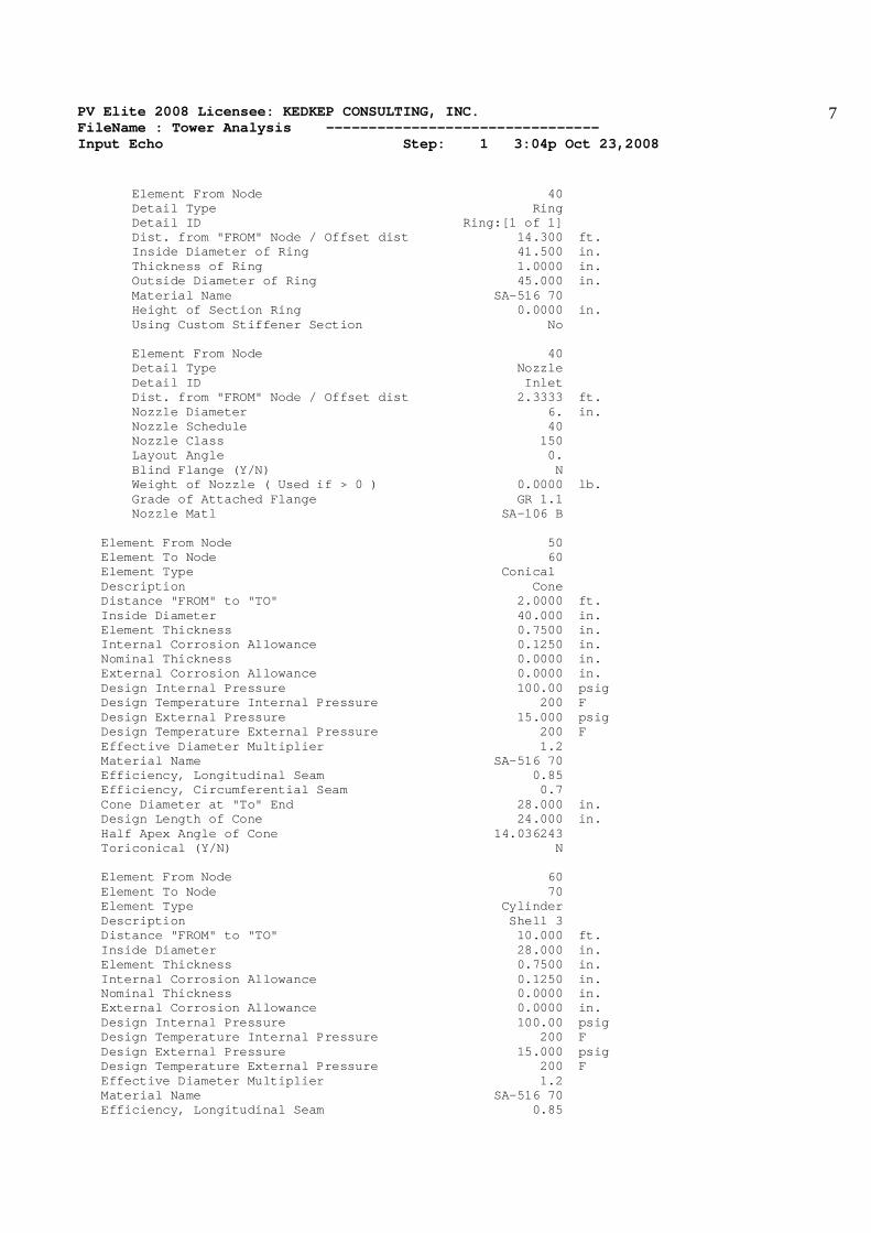
Element From Node 40 Detail Type Ring Detail ID Ring:[1 of 1] Dist. from "FROM" Node / Offset dist 14.300 ft. Inside Diameter of Ring 41.500 in. Thickness of Ring 1.0000 in. Outside Diameter of Ring 45.000 in. Material Name SA-516 70 Height of Section Ring 0.0000 in. Using Custom Stiffener Section No Element From Node 40 Detail Type Nozzle Detail ID Inlet Dist. from "FROM" Node / Offset dist 2.3333 ft. Nozzle Diameter 6. in. Nozzle Schedule 40 Nozzle Class 150 Layout Angle 0. Blind Flange (Y/N) N Weight of Nozzle ( Used if > 0 ) 0.0000 lb. Grade of Attached Flange GR 1.1 Nozzle Matl SA-106 B Element From Node 50 Element To Node 60 Element Type Conical Description Cone Distance "FROM" to "TO" 2.0000 ft. Inside Diameter 40.000 in. Element Thickness 0.7500 in. Internal Corrosion Allowance 0.1250 in. Nominal Thickness 0.0000 in. External Corrosion Allowance 0.0000 in. Design Internal Pressure 100.00 psig Design Temperature Internal Pressure 200 F Design External Pressure 15.000 psig Design Temperature External Pressure 200 F Effective Diameter Multiplier 1.2 Material Name SA-516 70 Efficiency, Longitudinal Seam 0.85 Efficiency, Circumferential Seam 0.7 Cone Diameter at "To" End 28.000 in. Design Length of Cone 24.000 in. Half Apex Angle of Cone 14.036243 Toriconical (Y/N) N Element From Node 60 Element To Node 70 Element Type Cylinder Description Shell 3 Distance "FROM" to "TO" 10.000 ft. Inside Diameter 28.000 in. Element Thickness 0.7500 in. Internal Corrosion Allowance 0.1250 in. Nominal Thickness 0.0000 in. External Corrosion Allowance 0.0000 in. Design Internal Pressure 100.00 psig Design Temperature Internal Pressure 200 F Design External Pressure 15.000 psig Design Temperature External Pressure 200 F Effective Diameter Multiplier 1.2 Material Name SA-516 70 Efficiency, Longitudinal Seam 0.85

PV Elite 2008 Licensee: KEDKEP CONSULTING, INC. FileName : Tower Analysis -------------------------------- Input Echo Step: 1 3:04p Oct 23,2008
8
Efficiency, Circumferential Seam 0.7 Element From Node 60 Detail Type Nozzle Detail ID Outlet Dist. from "FROM" Node / Offset dist 8.0000 ft. Nozzle Diameter 6. in. Nozzle Schedule 40 Nozzle Class 150 Layout Angle 0. Blind Flange (Y/N) N Weight of Nozzle ( Used if > 0 ) 0.0000 lb. Grade of Attached Flange GR 1.1 Nozzle Matl SA-106 B Element From Node 70 Element To Node 80 Element Type Elliptical Description Top Head Distance "FROM" to "TO" 0.1667 ft. Inside Diameter 28.000 in. Element Thickness 0.3750 in. Internal Corrosion Allowance 0.1250 in. Nominal Thickness 0.0000 in. External Corrosion Allowance 0.0000 in. Design Internal Pressure 100.00 psig Design Temperature Internal Pressure 200 F Design External Pressure 15.000 psig Design Temperature External Pressure 200 F Effective Diameter Multiplier 1.2 Material Name SA-516 70 Efficiency, Longitudinal Seam 0.85 Efficiency, Circumferential Seam 0.7 Elliptical Head Factor 2. Element From Node 70 Detail Type Nozzle Detail ID Vent Dist. from "FROM" Node / Offset dist 0.0000 in. Nozzle Diameter 2.5 in. Nozzle Schedule 80 Nozzle Class 150 Layout Angle 0. Blind Flange (Y/N) N Weight of Nozzle ( Used if > 0 ) 0.0000 lb. Grade of Attached Flange GR 1.1 Nozzle Matl SA-106 B PV Elite 2008 c1993-2008 by COADE Engineering Software
PV Elite 2008 Licensee: KEDKEP CONSULTING, INC. FileName : Tower Analysis -------------------------------- XY Coordinate Calculations Step: 2 3:04p Oct 23,2008
9
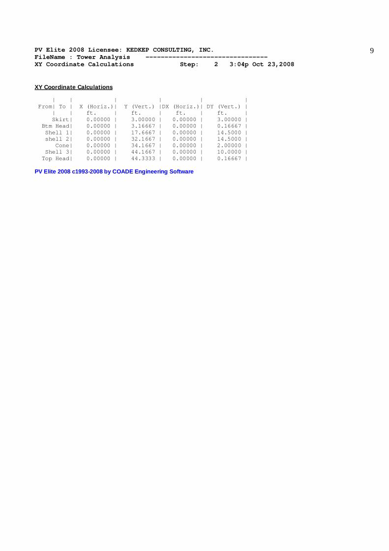
XY Coordinate Calculations | | | | | | From| To | X (Horiz.)| Y (Vert.) |DX (Horiz.)| DY (Vert.) | | | ft. | ft. | ft. | ft. | Skirt| 0.00000 | 3.00000 | 0.00000 | 3.00000 | Btm Head| 0.00000 | 3.16667 | 0.00000 | 0.16667 | Shell 1| 0.00000 | 17.6667 | 0.00000 | 14.5000 | shell 2| 0.00000 | 32.1667 | 0.00000 | 14.5000 | Cone| 0.00000 | 34.1667 | 0.00000 | 2.00000 | Shell 3| 0.00000 | 44.1667 | 0.00000 | 10.0000 | Top Head| 0.00000 | 44.3333 | 0.00000 | 0.16667 | PV Elite 2008 c1993-2008 by COADE Engineering Software
PV Elite 2008 Licensee: KEDKEP CONSULTING, INC. FileName : Tower Analysis -------------------------------- Internal Pressure Calculations Step: 3 3:04p Oct 23,2008
10
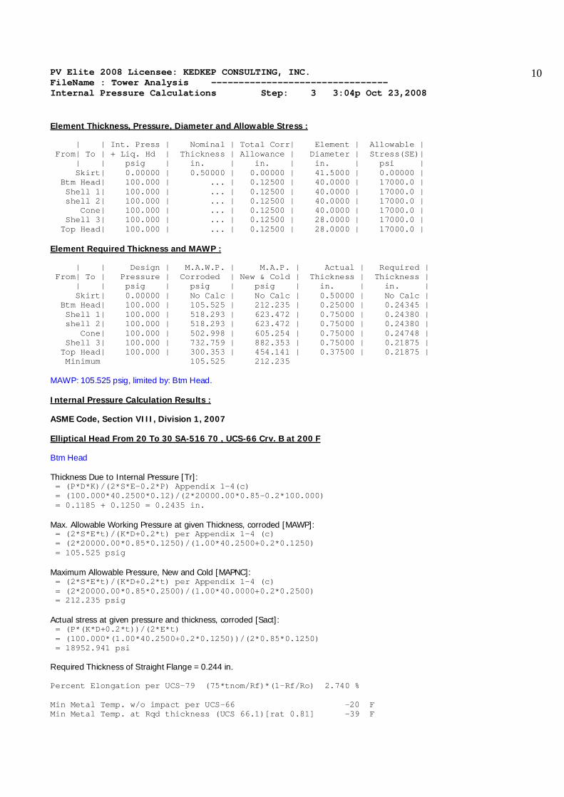
Element Thickness, Pressure, Diameter and Allowable Stress : | | Int. Press | Nominal | Total Corr| Element | Allowable | From| To | + Liq. Hd | Thickness | Allowance | Diameter | Stress(SE)| | | psig | in. | in. | in. | psi | Skirt| 0.00000 | 0.50000 | 0.00000 | 41.5000 | 0.00000 | Btm Head| 100.000 | ... | 0.12500 | 40.0000 | 17000.0 | Shell 1| 100.000 | ... | 0.12500 | 40.0000 | 17000.0 | shell 2| 100.000 | ... | 0.12500 | 40.0000 | 17000.0 | Cone| 100.000 | ... | 0.12500 | 40.0000 | 17000.0 | Shell 3| 100.000 | ... | 0.12500 | 28.0000 | 17000.0 | Top Head| 100.000 | ... | 0.12500 | 28.0000 | 17000.0 | Element Required Thickness and MAWP : | | Design | M.A.W.P. | M.A.P. | Actual | Required | From| To | Pressure | Corroded | New & Cold | Thickness | Thickness | | | psig | psig | psig | in. | in. | Skirt| 0.00000 | No Calc | No Calc | 0.50000 | No Calc | Btm Head| 100.000 | 105.525 | 212.235 | 0.25000 | 0.24345 | Shell 1| 100.000 | 518.293 | 623.472 | 0.75000 | 0.24380 | shell 2| 100.000 | 518.293 | 623.472 | 0.75000 | 0.24380 | Cone| 100.000 | 502.998 | 605.254 | 0.75000 | 0.24748 | Shell 3| 100.000 | 732.759 | 882.353 | 0.75000 | 0.21875 | Top Head| 100.000 | 300.353 | 454.141 | 0.37500 | 0.21875 | Minimum 105.525 212.235 MAWP: 105.525 psig, limited by: Btm Head. Internal Pressure Calculation Results : ASME Code, Section VIII, Division 1, 2007 Elliptical Head From 20 To 30 SA-516 70 , UCS-66 Crv. B at 200 F Btm Head Thickness Due to Internal Pressure [Tr]: = (P*D*K)/(2*S*E-0.2*P) Appendix 1-4(c) = (100.000*40.2500*0.12)/(2*20000.00*0.85-0.2*100.000) = 0.1185 + 0.1250 = 0.2435 in. Max. Allowable Working Pressure at given Thickness, corroded [MAWP]: = (2*S*E*t)/(K*D+0.2*t) per Appendix 1-4 (c) = (2*20000.00*0.85*0.1250)/(1.00*40.2500+0.2*0.1250) = 105.525 psig Maximum Allowable Pressure, New and Cold [MAPNC]: = (2*S*E*t)/(K*D+0.2*t) per Appendix 1-4 (c) = (2*20000.00*0.85*0.2500)/(1.00*40.0000+0.2*0.2500) = 212.235 psig Actual stress at given pressure and thickness, corroded [Sact]: = (P*(K*D+0.2*t))/(2*E*t) = (100.000*(1.00*40.2500+0.2*0.1250))/(2*0.85*0.1250) = 18952.941 psi Required Thickness of Straight Flange = 0.244 in. Percent Elongation per UCS-79 (75*tnom/Rf)*(1-Rf/Ro) 2.740 % Min Metal Temp. w/o impact per UCS-66 -20 F Min Metal Temp. at Rqd thickness (UCS 66.1)[rat 0.81] -39 F

PV Elite 2008 Licensee: KEDKEP CONSULTING, INC. FileName : Tower Analysis -------------------------------- Internal Pressure Calculations Step: 3 3:04p Oct 23,2008
11
Cylindrical Shell From 30 To 40 SA-516 70 , UCS-66 Crv. B at 200 F Shell 1 Thickness Due to Internal Pressure [Tr]: = (P*R)/(S*E-0.6*P) per UG-27 (c)(1) = (100.000*20.1250)/(20000.00*0.85-0.6*100.000) = 0.1188 + 0.1250 = 0.2438 in. Max. Allowable Working Pressure at given Thickness, corroded [MAWP]: = (S*E*t)/(R+0.6*t) per UG-27 (c)(1) = (20000.00*0.85*0.6250)/(20.1250+0.6*0.6250) = 518.293 psig Maximum Allowable Pressure, New and Cold [MAPNC]: = (S*E*t)/(R+0.6*t) per UG-27 (c)(1) = (20000.00*0.85*0.7500)/(20.0000+0.6*0.7500) = 623.472 psig Actual stress at given pressure and thickness, corroded [Sact]: = (P*(R+0.6*t))/(E*t) = (100.000*(20.1250+0.6*0.6250))/(0.85*0.6250) = 3858.823 psi Percent Elongation per UCS-79 (50*tnom/Rf)*(1-Rf/Ro) 1.840 % Min Metal Temp. w/o impact per UCS-66 16 F Min Metal Temp. at Rqd thickness (UCS 66.1)[rat 0.16] -124 F Min Metal Temp. w/o impact per UG-20(f) -20 F Cylindrical Shell From 40 To 50 SA-516 70 , UCS-66 Crv. B at 200 F shell 2 Thickness Due to Internal Pressure [Tr]: = (P*R)/(S*E-0.6*P) per UG-27 (c)(1) = (100.000*20.1250)/(20000.00*0.85-0.6*100.000) = 0.1188 + 0.1250 = 0.2438 in. Max. Allowable Working Pressure at given Thickness, corroded [MAWP]: = (S*E*t)/(R+0.6*t) per UG-27 (c)(1) = (20000.00*0.85*0.6250)/(20.1250+0.6*0.6250) = 518.293 psig Maximum Allowable Pressure, New and Cold [MAPNC]: = (S*E*t)/(R+0.6*t) per UG-27 (c)(1) = (20000.00*0.85*0.7500)/(20.0000+0.6*0.7500) = 623.472 psig Actual stress at given pressure and thickness, corroded [Sact]: = (P*(R+0.6*t))/(E*t) = (100.000*(20.1250+0.6*0.6250))/(0.85*0.6250) = 3858.823 psi Percent Elongation per UCS-79 (50*tnom/Rf)*(1-Rf/Ro) 1.840 % Min Metal Temp. w/o impact per UCS-66 16 F Min Metal Temp. at Rqd thickness (UCS 66.1)[rat 0.16] -124 F Min Metal Temp. w/o impact per UG-20(f) -20 F Conical Section From 50 To 60 SA-516 70 , UCS-66 Crv. B at 200 F Cone Thickness Due to Internal Pressure [Tr]:

PV Elite 2008 Licensee: KEDKEP CONSULTING, INC. FileName : Tower Analysis -------------------------------- Internal Pressure Calculations Step: 3 3:04p Oct 23,2008
12
= (P*D)/(2*cos(a)*(S*E-0.6*P)) per Appendix 1-4 (e) = (100.000*40.1288)/(2*0.9701*(20000.00*0.85-0.6*100.000)) = 0.1225 + 0.1250 = 0.2475 in. Max. Allowable Working Pressure at given Thickness, corroded [MAWP]: = (2*S*E*t*cos(a))/(D+1.2*t*cos(a)) per App 1-4(e) = (2*20000.00*0.85*0.625*0.970)/(40.129+1.2*0.625*0.970) = 502.998 psig Maximum Allowable Pressure, New and Cold [MAPNC]: = (2*S*E*t*cos(a))/(D+1.2*t*cos(a)) per App 1-4(e) = (2*20000.00*0.85*0.7500*0.9701)/(40.0000+1.2*0.7500*0.9701) = 605.254 psig Actual stress at given pressure and thickness, corroded [Sact]: = (P*(D+1.2*t*cos(a)))/(2*E*t*cos(a)) = (100.000*(40.1288+1.2*0.6250*0.9701))/(2*0.85*0.6250*0.9701) = 3976.158 psi Percent Elongation per UCS-79 (75*tnom/Rf)*(1-Rf/Ro) 2.607 % Min Metal Temp. w/o impact per UCS-66 16 F Min Metal Temp. at Rqd thickness (UCS 66.1)[rat 0.17] -124 F Min Metal Temp. w/o impact per UG-20(f) -20 F Cylindrical Shell From 60 To 70 SA-516 70 , UCS-66 Crv. B at 200 F Shell 3 Thickness Due to Internal Pressure [Tr]: = (P*R)/(S*E-0.6*P) per UG-27 (c)(1) = (100.000*14.1250)/(20000.00*0.85-0.6*100.000) = 0.0834 + 0.1250 = 0.2084 in. Note: The thickness required was less than the Code Minimum, therefore the Code Minimum value of 0.0938 in. will be used. Max. Allowable Working Pressure at given Thickness, corroded [MAWP]: = (S*E*t)/(R+0.6*t) per UG-27 (c)(1) = (20000.00*0.85*0.6250)/(14.1250+0.6*0.6250) = 732.759 psig Maximum Allowable Pressure, New and Cold [MAPNC]: = (S*E*t)/(R+0.6*t) per UG-27 (c)(1) = (20000.00*0.85*0.7500)/(14.0000+0.6*0.7500) = 882.353 psig Actual stress at given pressure and thickness, corroded [Sact]: = (P*(R+0.6*t))/(E*t) = (100.000*(14.1250+0.6*0.6250))/(0.85*0.6250) = 2729.412 psi Percent Elongation per UCS-79 (50*tnom/Rf)*(1-Rf/Ro) 2.609 % Min Metal Temp. w/o impact per UCS-66 16 F Min Metal Temp. at Rqd thickness (UCS 66.1)[rat 0.13] -124 F Min Metal Temp. w/o impact per UG-20(f) -20 F Elliptical Head From 70 To 80 SA-516 70 , UCS-66 Crv. B at 200 F Top Head Thickness Due to Internal Pressure [Tr]: = (P*D*K)/(2*S*E-0.2*P) Appendix 1-4(c) = (100.000*28.2500*0.12)/(2*20000.00*0.85-0.2*100.000)
PV Elite 2008 Licensee: KEDKEP CONSULTING, INC. FileName : Tower Analysis -------------------------------- Internal Pressure Calculations Step: 3 3:04p Oct 23,2008
13
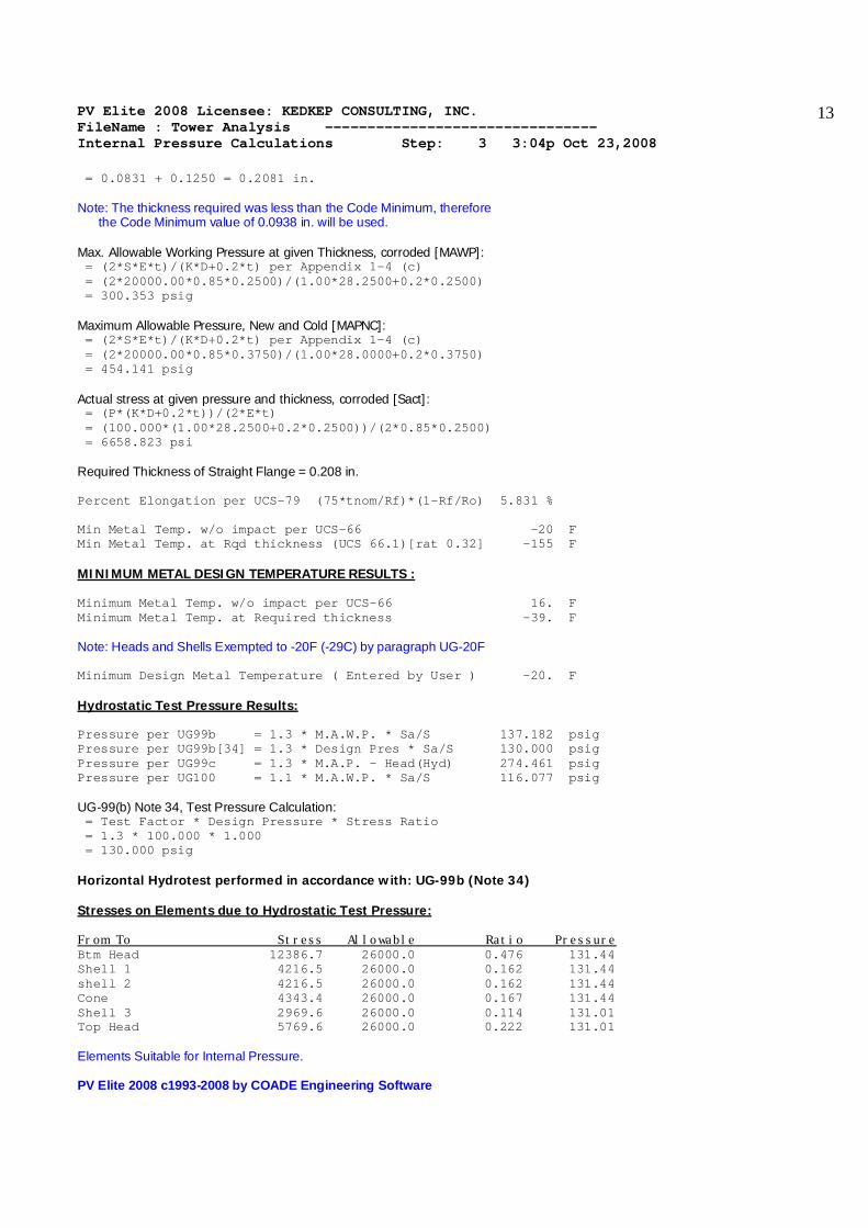
= 0.0831 + 0.1250 = 0.2081 in. Note: The thickness required was less than the Code Minimum, therefore the Code Minimum value of 0.0938 in. will be used. Max. Allowable Working Pressure at given Thickness, corroded [MAWP]: = (2*S*E*t)/(K*D+0.2*t) per Appendix 1-4 (c) = (2*20000.00*0.85*0.2500)/(1.00*28.2500+0.2*0.2500) = 300.353 psig Maximum Allowable Pressure, New and Cold [MAPNC]: = (2*S*E*t)/(K*D+0.2*t) per Appendix 1-4 (c) = (2*20000.00*0.85*0.3750)/(1.00*28.0000+0.2*0.3750) = 454.141 psig Actual stress at given pressure and thickness, corroded [Sact]: = (P*(K*D+0.2*t))/(2*E*t) = (100.000*(1.00*28.2500+0.2*0.2500))/(2*0.85*0.2500) = 6658.823 psi Required Thickness of Straight Flange = 0.208 in. Percent Elongation per UCS-79 (75*tnom/Rf)*(1-Rf/Ro) 5.831 % Min Metal Temp. w/o impact per UCS-66 -20 F Min Metal Temp. at Rqd thickness (UCS 66.1)[rat 0.32] -155 F MINIMUM METAL DESIGN TEMPERATURE RESULTS : Minimum Metal Temp. w/o impact per UCS-66 16. F Minimum Metal Temp. at Required thickness -39. F Note: Heads and Shells Exempted to -20F (-29C) by paragraph UG-20F Minimum Design Metal Temperature ( Entered by User ) -20. F Hydrostatic Test Pressure Results: Pressure per UG99b = 1.3 * M.A.W.P. * Sa/S 137.182 psig Pressure per UG99b[34] = 1.3 * Design Pres * Sa/S 130.000 psig Pressure per UG99c = 1.3 * M.A.P. - Head(Hyd) 274.461 psig Pressure per UG100 = 1.1 * M.A.W.P. * Sa/S 116.077 psig UG-99(b) Note 34, Test Pressure Calculation: = Test Factor * Design Pressure * Stress Ratio = 1.3 * 100.000 * 1.000 = 130.000 psig Horizontal Hydrotest performed in accordance with: UG-99b (Note 34) Stresses on Elements due to Hydrostatic Test Pressure: From To Stress Allowable Ratio Pressure Btm Head 12386.7 26000.0 0.476 131.44 Shell 1 4216.5 26000.0 0.162 131.44 shell 2 4216.5 26000.0 0.162 131.44 Cone 4343.4 26000.0 0.167 131.44 Shell 3 2969.6 26000.0 0.114 131.01 Top Head 5769.6 26000.0 0.222 131.01 Elements Suitable for Internal Pressure. PV Elite 2008 c1993-2008 by COADE Engineering Software

PV Elite 2008 Licensee: KEDKEP CONSULTING, INC. FileName : Tower Analysis -------------------------------- External Pressure Calculations Step: 4 3:04p Oct 23,2008
14
External Pressure Calculation Results : ASME Code, Section VIII, Division 1, 2007 Elliptical Head From 20 to 30 Ext. Chart: CS-2 at 200 F Btm Head Elastic Modulus from Chart: CS-2 at 300 F : 0.29000E+08 psi Results for Maximum Allowable External Pressure (MAEP): Tca OD D/t Factor A B 0.125 40.50 324.00 0.0004287 6215.71 EMAP = B/(K0*D/t) = 6215.7065 /(0.9000 *324.0000 ) = 21.3159 psig Results for Required Thickness (Tca): Tca OD D/t Factor A B 0.105 40.50 386.22 0.0003596 5214.37 EMAP = B/(K0*D/t) = 5214.3701 /(0.9000 *386.2190 ) = 15.0012 psig Cylindrical Shell From 30 to 40 Ext. Chart: CS-2 at 200 F Shell 1 Elastic Modulus from Chart: CS-2 at 300 F : 0.29000E+08 psi Results for Maximum Allowable External Pressure (MAEP): Tca OD SLEN D/t L/D Factor A B 0.625 41.50 350.93 66.40 8.4562 0.0002860 4146.94 EMAP = (4*B)/(3*(D/t)) = (4*4146.9438 )/(3*66.4000 ) = 83.2720 psig Results for Required Thickness (Tca): Tca OD SLEN D/t L/D Factor A B 0.315 41.50 350.93 131.70 8.4562 0.0001022 1481.70 EMAP = (4*B)/(3*(D/t)) = (4*1481.7010 )/(3*131.7028 ) = 15.0004 psig Results for Maximum Stiffened Length (Slen): Tca OD SLEN D/t L/D Factor A B 0.625 41.50 0.53E+25 66.40 .5000E+02 0.0002495 3617.63 EMAP = (4*B)/(3*(D/t)) = (4*3617.6328 )/(3*66.4000 ) = 72.6432 psig Cylindrical Shell From 40 to Ring:[1 of 1] Ext. Chart: CS-2 at 200 F shell 2 Elastic Modulus from Chart: CS-2 at 300 F : 0.29000E+08 psi Results for Maximum Allowable External Pressure (MAEP): Tca OD SLEN D/t L/D Factor A B 0.625 41.50 350.93 66.40 8.4562 0.0002860 4146.94 EMAP = (4*B)/(3*(D/t)) = (4*4146.9438 )/(3*66.4000 ) = 83.2720 psig Results for Required Thickness (Tca): Tca OD SLEN D/t L/D Factor A B 0.315 41.50 350.93 131.70 8.4562 0.0001022 1481.70 EMAP = (4*B)/(3*(D/t)) = (4*1481.7010 )/(3*131.7028 ) = 15.0004 psig Results for Maximum Stiffened Length (Slen): Tca OD SLEN D/t L/D Factor A B 0.625 41.50 0.53E+25 66.40 .5000E+02 0.0002495 3617.63 EMAP = (4*B)/(3*(D/t)) = (4*3617.6328 )/(3*66.4000 ) = 72.6432 psig Cone From 50 to 60 Ext. Chart: CS-2 at 200 F

PV Elite 2008 Licensee: KEDKEP CONSULTING, INC. FileName : Tower Analysis -------------------------------- External Pressure Calculations Step: 4 3:04p Oct 23,2008
15
Cone Elastic Modulus from Chart: CS-2 at 300 F : 0.29000E+08 psi Results for Maximum Allowable External Pressure (MAEP): Tca OD SLEN D/t L/D Factor A B 0.606 41.55 20.53 68.52 0.4942 0.0052117 17384.15 EMAP = (4*B)/(3*(D/t)) = (4*17384.1523)/(3*68.5197 ) = 338.2805 psig Note: The cone thickness used in the calculation has been modified per UG-33(f), te = t * cos(alpha). Results for Required Thickness (Tca): Tca OD SLEN D/t L/D Factor A B 0.100 41.55 20.53 416.90 0.4942 0.0003235 4690.47 EMAP = (4*B)/(3*(D/t)) = (4*4690.4688 )/(3*416.9009 ) = 15.0011 psig Note: The cone thickness used in the calculation has been modified per UG-33(f), te = t * cos(alpha). Cylindrical Shell From 60 to 70 Ext. Chart: CS-2 at 200 F Shell 3 Elastic Modulus from Chart: CS-2 at 300 F : 0.29000E+08 psi Results for Maximum Allowable External Pressure (MAEP): Tca OD SLEN D/t L/D Factor A B 0.625 29.50 124.33 47.20 4.2147 0.0009662 12216.94 EMAP = (4*B)/(3*(D/t)) = (4*12216.9355)/(3*47.2000 ) = 345.1112 psig Results for Required Thickness (Tca): Tca OD SLEN D/t L/D Factor A B 0.169 29.50 124.33 174.25 4.2147 0.0001352 1960.33 EMAP = (4*B)/(3*(D/t)) = (4*1960.3263 )/(3*174.2460 ) = 15.0004 psig Results for Maximum Stiffened Length (Slen): Tca OD SLEN D/t L/D Factor A B 0.625 29.50 0.24E+30 47.20 .5000E+02 0.0004938 7159.40 EMAP = (4*B)/(3*(D/t)) = (4*7159.4019 )/(3*47.2000 ) = 202.2430 psig Elliptical Head From 70 to 80 Ext. Chart: CS-2 at 200 F Top Head Elastic Modulus from Chart: CS-2 at 300 F : 0.29000E+08 psi Results for Maximum Allowable External Pressure (MAEP): Tca OD D/t Factor A B 0.250 28.75 115.00 0.0012077 13182.19 EMAP = B/(K0*D/t) = 13182.1865/(0.9000 *115.0000 ) = 127.3641 psig Results for Required Thickness (Tca): Tca OD D/t Factor A B 0.074 28.75 386.22 0.0003596 5214.36 EMAP = B/(K0*D/t) = 5214.3579 /(0.9000 *386.2199 ) = 15.0011 psig Stiffening Ring Calculations for : Ring:[1 of 1], SA-516 70 Effective Length of Shell 5.60 in. Area (sq.in.) Distance (in.) Area*Dist Shell: 3.501 0.3125 1.094 Ring : 1.750 1.5000 2.625 Total: 5.251 3.719 Centroid of Ring plus Shell = 0.708 in. Inertia Distance A*Dist2

PV Elite 2008 Licensee: KEDKEP CONSULTING, INC. FileName : Tower Analysis -------------------------------- External Pressure Calculations Step: 4 3:04p Oct 23,2008
16
Shell: 0.114 0.3957 0.548 Ring : 0.447 -0.7918 1.097 Total: 0.561 1.645 Available Moment of Inertia, Ring plus Shell 2.206 in**4 Required Stress in Ring plus Shell BREQ 735.35 psi Required Strain in Ring plus Shell AREQ 0.0000507 Required Moment of Inertia, Ring plus Shell = ( OD2 * SLEN * (TCA+ARING/SLEN) * AREQ )/ 10.9 = (41.50002*176.6667*(0.6250+1.7500/176.6667)*0.0000507)/10.9 = 0.8988 in**4 Results for Stiffening Ring Weld Calculations per UG-30 Given Stiffening Ring Fillet Weld Size Wleg 0.500 in. Stiffening Ring Attachment Style BOTH Location of Stiffening Ring EXTERNAL Radial Pressure Load Pext*Slen 2650.00 lb./in. The Radial Shear Load V 1099.75 lb. The First Moment of the Area ( Ring + Shell ) Q 1.39 in.3 Weld Shear Flow due to Rad. Shear Load VQ/I 690.76 lb./in The Weld Allowable Stress .55*S 11000.00 psi Minimum Weld Leg Size Min(.25,TCA,TRING) Wldmin 0.25 in. Maximum Space between Welds 24*TCA 15.00 in. The Weld Allowable Load WLeg*.55*S 5500.00 lb./in The Combined Weld Load SRSS of VQ/I and Pext*Slen 2738.55 lb./in External Pressure Calculations | | Section | Outside | Corroded | Factor | Factor | From| To | Length | Diameter | Thickness | A | B | | | ft. | in. | in. | | psi | 10| 20| No Calc | 0.00000 | 0.00000 | No Calc | No Calc | 20| 30| No Calc | 40.5000 | 0.12500 | 0.00042867 | 6215.71 | 30| 40| 29.2444 | 41.5000 | 0.62500 | 0.00028600 | 4146.94 | 40|Ring| 29.2444 | 41.5000 | 0.62500 | 0.00028600 | 4146.94 | Ring| 50| 0.20000 | 41.5000 | 0.62500 | 0.92155 | 17800.0 | 50| 60| 1.71084 | 41.5462 | 0.62500 | 0.0052117 | 17384.2 | 60| 70| 10.3611 | 29.5000 | 0.62500 | 0.00096620 | 12216.9 | 70| 80| No Calc | 28.7500 | 0.25000 | 0.0012077 | 13182.2 | External Pressure Calculations | | External | External | External | External | From| To | Actual T. | Required T.|Des. Press. | M.A.W.P. | | | in. | in. | psig | psig | 10| 20| 0.00000 | No Calc | 0.00000 | No Calc | 20| 30| 0.25000 | 0.22986 | 15.0000 | 21.3159 | 30| 40| 0.75000 | 0.44010 | 15.0000 | 83.2720 | 40|Ring| 0.75000 | 0.44010 | 15.0000 | 83.2720 | Ring| 50| 0.75000 | 0.16469 | 15.0000 | 357.430 | 50| 60| 0.75000 | 0.22772 | 15.0000 | 338.280 | 60| 70| 0.75000 | 0.29430 | 15.0000 | 345.111 | 70| 80| 0.37500 | 0.19944 | 15.0000 | 127.364 | Minimum 21.316 External Pressure Calculations | | Actual Len.| Allow. Len.| Ring Inertia | Ring Inertia | From| To | Bet. Stiff.| Bet. Stiff.| Required | Available | | | ft. | ft. | in**4 | in**4 | 10| 20| No Calc | No Calc | No Calc | No Calc | 20| 30| No Calc | No Calc | No Calc | No Calc | 30| 40| 29.2444 | 442.4E+21 | No Calc | No Calc | 40|Ring| 29.2444 | 442.4E+21 | No Calc | No Calc |

PV Elite 2008 Licensee: KEDKEP CONSULTING, INC. FileName : Tower Analysis -------------------------------- External Pressure Calculations Step: 4 3:04p Oct 23,2008
17
Ring| 50| 0.20000 | 8.656E+21 | 0.89879 | 2.20599 | 50| 60| 1.71084 | 1.71084 | No Calc | No Calc | 60| 70| 10.3611 | 19.68E+27 | No Calc | No Calc | 70| 80| No Calc | No Calc | No Calc | No Calc | Elements Suitable for External Pressure. PV Elite 2008 c1993-2008 by COADE Engineering Software

PV Elite 2008 Licensee: KEDKEP CONSULTING, INC. FileName : Tower Analysis -------------------------------- Element and Detail Weights Step: 5 3:04p Oct 23,2008
18
Element and Detail Weights | | Element | Element | Corroded | Corroded | Extra due | From| To | Metal Wgt. | ID Volume |Metal Wgt. | ID Volume | Misc % | | | lb. | in3 | lb. | in3 | lb. | 10| 20| 1244.54 | 0.00000 | 1244.54 | 0.00000 | 248.908 | 20| 30| 155.075 | 10890.9 | 77.5376 | 11080.4 | 31.0150 | 30| 40| 4727.97 | 218655. | 3952.06 | 221397. | 945.593 | 40| 50| 4727.97 | 218655. | 3952.06 | 221397. | 945.593 | 50| 60| 573.610 | 22016.3 | 479.780 | 22347.8 | 114.722 | 60| 70| 2300.47 | 73890.3 | 1925.39 | 75215.6 | 460.094 | 70| 80| 121.186 | 4105.01 | 80.7908 | 4204.76 | 24.2373 | --------------------------------------------------------------------------- Total 13850 548212 11712 555641 2770 Weight of Details | | Weight of | X Offset, | Y Offset, | From|Type| Detail | Dtl. Cent. |Dtl. Cent. | Description | | lb. | ft. | ft. | 20|Nozl| 18.1522 | 0.00000 | 0.069444 | Drain 30|Nozl| 206.641 | 2.33333 | 3.00000 | Manway 40|Ring| 80.7499 | 0.00000 | 14.3000 | Ring:[1 of 1] 40|Nozl| 33.9274 | 1.91667 | 2.33333 | Inlet 60|Nozl| 33.9274 | 1.41667 | 8.00000 | Outlet 70|Nozl| 14.8816 | 0.00000 | 0.048611 | Vent Total Weight of Each Detail Type Total Weight of Stiffeners 80.7 Total Weight of Nozzles 307.5 --------------------------------------------------------------- Sum of the Detail Weights 388.3 lb. Weight Summary Fabricated Wt. - Bare Weight W/O Removable Internals 17009.3 lb. Shop Test Wt. - Fabricated Weight + Water ( Full ) 36805.8 lb. Shipping Wt. - Fab. Wt + Rem. Intls.+ Shipping App. 17009.3 lb. Erected Wt. - Fab. Wt + Rem. Intls.+ Insul. (etc) 17009.3 lb. Ope. Wt. no Liq - Fab. Wt + Intls. + Details + Wghts. 17009.3 lb. Operating Wt. - Empty Wt. + Operating Liquid (No CA) 17009.3 lb. Field Test Wt. - Empty Weight + Water (Full) 36805.8 lb. Mass of the Upper 1/3 of the Vertical Vessel 3966.7 lb. Outside Surface Areas of Elements | | Surface | From| To | Area | | | sq.in. | 10| 20| 4806.64 | 20| 30| 2032.48 | 30| 40| 22685.4 | 40| 50| 22685.4 | 50| 60| 2762.60 | 60| 70| 11121.2 | 70| 80| 1076.62 | ----------------------------------------------------- Total 67170.461 sq.in. [466.5 Square Feet ] Element and Detail Weights | To | Total Ele.| Total. Ele.|Total. Ele.| Total Dtl.| Oper. Wgt. | From| To | Empty Wgt.| Oper. Wgt.|Hydro. Wgt.| Offset Mom.| No Liquid |

PV Elite 2008 Licensee: KEDKEP CONSULTING, INC. FileName : Tower Analysis -------------------------------- Element and Detail Weights Step: 5 3:04p Oct 23,2008
19
| | lbm | lbm | lbm | ft.lb. | lbm | 10| 20| 1493.45 | 1493.45 | 1493.45 | 0.00000 | 1493.45 | 20| 30| 204.242 | 204.242 | 597.523 | 0.00000 | 204.242 | 30| 40| 5880.20 | 5880.20 | 13776.1 | 482.163 | 5880.20 | 40| 50| 5788.24 | 5788.24 | 13684.1 | 65.0275 | 5788.24 | 50| 60| 688.332 | 688.332 | 1483.36 | 0.00000 | 688.332 | 60| 70| 2794.49 | 2794.49 | 5462.75 | 48.0638 | 2794.49 | 70| 80| 160.305 | 160.305 | 308.542 | 0.00000 | 160.305 | Cumulative Vessel Weight | | Cumulative Ope | Cumulative | Cumulative | From| To | Wgt. No Liquid | Oper. Wgt. | Hydro. Wgt. | | | lbm | lbm | lbm | 10| 20| 17009.3 | 17009.3 | 36805.8 | 20| 30| 15515.8 | 15515.8 | 35312.4 | 30| 40| 15311.6 | 15311.6 | 34714.8 | 40| 50| 9431.37 | 9431.37 | 20938.8 | 50| 60| 3643.13 | 3643.13 | 7254.66 | 60| 70| 2954.80 | 2954.80 | 5771.29 | 70| 80| 160.305 | 160.305 | 308.542 | Note: The cumulative operating weights no liquid in the column above are the cumulative operating weights minus the operating liquid weight minus any weights absent in the empty condition. Cumulative Vessel Moment | | Cumulative | Cumulative |Cumulative | From| To | Empty Mom. | Oper. Mom. |Hydro. Mom.| | | ft.lb. | ft.lb. | ft.lb. | 10| 20| 595.255 | 595.255 | 595.255 | 20| 30| 595.255 | 595.255 | 595.255 | 30| 40| 595.255 | 595.255 | 595.255 | 40| 50| 113.091 | 113.091 | 113.091 | 50| 60| 48.0638 | 48.0638 | 48.0638 | 60| 70| 48.0638 | 48.0638 | 48.0638 | 70| 80| 0.00000 | 0.00000 | 0.00000 | PV Elite 2008 c1993-2008 by COADE Engineering Software
PV Elite 2008 Licensee: KEDKEP CONSULTING, INC. FileName : Tower Analysis -------------------------------- Nozzle Flange MAWP Step: 6 3:04p Oct 23,2008
20
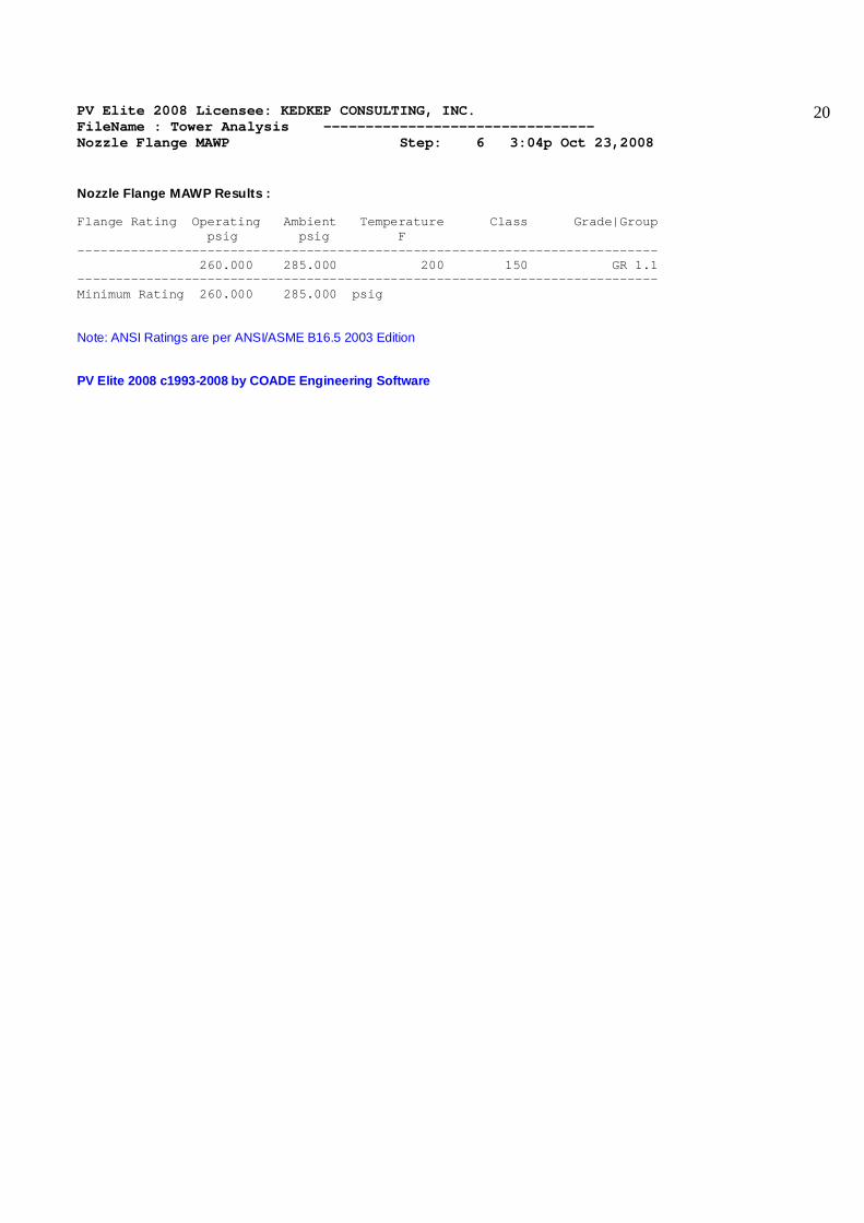
Nozzle Flange MAWP Results : Flange Rating Operating Ambient Temperature Class Grade|Group psig psig F ---------------------------------------------------------------------------- 260.000 285.000 200 150 GR 1.1 ---------------------------------------------------------------------------- Minimum Rating 260.000 285.000 psig Note: ANSI Ratings are per ANSI/ASME B16.5 2003 Edition PV Elite 2008 c1993-2008 by COADE Engineering Software

PV Elite 2008 Licensee: KEDKEP CONSULTING, INC. FileName : Tower Analysis -------------------------------- Natural Frequency Calculation Step: 7 3:04p Oct 23,2008
21
The Natural Frequencies for the vessel have been computed iteratively by solving a system of matrices. These matrices describe the mass and the stiffness of the vessel. This is the generalized eigenvalue/ eigenvector problem and is referenced in some mathematical texts. The Natural Frequency for the Vessel (Empty.) is 4.68398 Hz. The Natural Frequency for the Vessel (Ope...) is 4.68398 Hz. PV Elite 2008 c1993-2008 by COADE Engineering Software

PV Elite 2008 Licensee: KEDKEP CONSULTING, INC. FileName : Tower Analysis -------------------------------- Wind Load Calculation Step: 8 3:04p Oct 23,2008
22
Wind Load Results per National Building Code of Canada 2005 Static Pressure q 13.23 psf Gust Factor Cg 3.480 Pressure Coefficient Cp 0.665 Exposure Category B Importance Factor from Table 4.1.7.1 Iw 1.00 Equation to determine the Wind Pressure at level h [p(h)]: = Iw * q * Ce(height,Exp) * Cg * Cp [4.1.7.1](2005) Intermediate values for each element are shown below: Element Ce Cg Iw q ------------------------------------------------------------------- Skirt 0.500 3.480 1.000 13.230 Btm Head 0.500 3.480 1.000 13.230 Shell 1 0.500 3.480 1.000 13.230 shell 2 0.500 3.480 1.000 13.230 Cone 0.500 3.480 1.000 13.230 Shell 3 0.500 3.480 1.000 13.230 Top Head 0.517 3.480 1.000 13.230 Terms involving the calculation of Cg Note: The figures referenced below are from the NBC 2005 edition Background Turbulence Factor from Figure I-18 [B]: = 1.604 Size Reduction Factor from Figure I-19 [s]: = 0.048 Gust Energy ratio from Figure I-20 [F]: = 0.025 Peak Factor from Figure I-20 [gP]: = 4.265 Value of sigma/mu [sigma/mu]: = sqrt( K/CeH * ( B + S * F / Beta )) = sqrt( 0.100 / 0.519 * ( 1.604 + 0.048 * 0.025 / 0.008 )) = 0.581 Value of the Gust Effect Factor [Cg]: = 1 + gP( sigma/mu ) = 1 + 4.265 ( 0.581 ) = 3.480 Wind Pressure on the first element [p]: = Iw * q * Ce * Cg = 1.00 * 13.230 * 0.500 * 3.480 = 23.017 psf Force on the first element [F]: = p * Wind Area * Shape Factor = 23.02 * 12.750 * 0.665 = 195.259 lb. Wind Vibration Calculations This evaluation is based on work by Kanti Mahajan and Ed Zorilla

PV Elite 2008 Licensee: KEDKEP CONSULTING, INC. FileName : Tower Analysis -------------------------------- Wind Load Calculation Step: 8 3:04p Oct 23,2008
23
Nomenclature Cf - Correction factor for natural frequency D - Average internal diameter of vessel ft. Df - Damping Factor < 0.75 Unstable, > 0.95 Stable Dr - Average internal diameter of top half of vessel ft. f - Natural frequency of vibration (Hertz) f1 - Natural frequency of bare vessel based on a unit value of (D/L2)(104) L - Total height of structure ft. Lc - Total length of conical section(s) of vessel ft. tb - Uncorroded plate thickness at bottom of vessel in. V30 - Design Wind Speed provided by user mile/hr Vc - Critical wind velocity mile/hr Vw - Maximum wind speed at top of structure mile/hr W - Total corroded weight of structure lb. Ws - Cor. vessel weight excl. weight of parts which do not effect stiff. lb. Z - Maximum amplitude of vibration at top of vessel in. Dl - Logarithmic decrement ( taken as 0.03 for Welded Structures ) Vp - Vib. Chance, <= 0.200E+02 (High); 0.200E+02 < 0.250E+02 (Probable) P30 - wind pressure 30 feet above the base Check other Conditions and Basic Assumptions: #1 - Total Cone Length / Total Length < 0.5 2.000 / 44.333 = 0.045 #2 - ( D / L2 ) * 104 < 8.0 (English Units) - ( 3.21 / 44.332 ) * 104 = 16.340 [Geometry Violation] Compute the vibration possibility. If Vp > 0.250E+02 no chance. [Vp]: = W / ( L * Dr2) = 14442 / ( 44.33 * 2.8502 ) = 40.097 Since Vp is > 0.250E+02 no further vibration analysis is required ! The Natural Frequency for the Vessel (Ope...) is 4.68398 Hz. Wind Load Calculation | | Wind | Wind | Wind | Height | Element | From| To | Height | Diameter | Area | Factor | Wind Load | | | ft. | ft. | sq.in. | psf | lb. | 10| 20| 1.50000 | 4.25000 | 1836.00 | 23.0175 | 195.259 | 20| 30| 3.08333 | 4.05000 | 97.2000 | 23.0175 | 10.3372 | 30| 40| 10.4167 | 4.15000 | 8665.20 | 23.0175 | 921.545 | 40| 50| 24.9167 | 4.15000 | 8665.20 | 23.0175 | 921.545 | 50| 60| 33.1078 | 3.55000 | 1022.40 | 23.0175 | 108.732 | 60| 70| 39.1667 | 2.95000 | 4248.00 | 23.0175 | 451.775 | 70| 80| 44.5058 | 2.87500 | 268.835 | 23.7882 | 29.5479 | PV Elite 2008 c1993-2008 by COADE Engineering Software
PV Elite 2008 Licensee: KEDKEP CONSULTING, INC. FileName : Tower Analysis -------------------------------- Earthquake Load Calculation Step: 9 3:04p Oct 23,2008
24
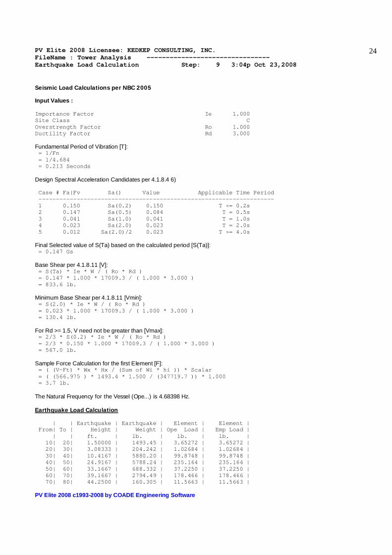
Seismic Load Calculations per NBC 2005 Input Values : Importance Factor Ie 1.000 Site Class C Overstrength Factor Ro 1.000 Ductility Factor Rd 3.000 Fundamental Period of Vibration [T]: = 1/Fn = 1/4.684 = 0.213 Seconds Design Spectral Acceleration Candidates per 4.1.8.4 6) Case # Fa|Fv Sa() Value Applicable Time Period -------------------------------------------------------------------- 1 0.150 Sa(0.2) 0.150 T <= 0.2s 2 0.147 Sa(0.5) 0.084 T = 0.5s 3 0.041 Sa(1.0) 0.041 T = 1.0s 4 0.023 Sa(2.0) 0.023 T = 2.0s 5 0.012 Sa(2.0)/2 0.023 T >= 4.0s Final Selected value of S(Ta) based on the calculated period [S(Ta)]: = 0.147 Gs Base Shear per 4.1.8.11 [V]: = S(Ta) * Ie * W / ( Ro * Rd ) = 0.147 * 1.000 * 17009.3 / ( 1.000 * 3.000 ) = 833.6 lb. Minimum Base Shear per 4.1.8.11 [Vmin]: = S(2.0) * Ie * W / ( Ro * Rd ) = 0.023 * 1.000 * 17009.3 / ( 1.000 * 3.000 ) = 130.4 lb. For Rd >= 1.5, V need not be greater than [Vmax]: = 2/3 * S(0.2) * Ie * W / ( Ro * Rd ) = 2/3 * 0.150 * 1.000 * 17009.3 / ( 1.000 * 3.000 ) = 567.0 lb. Sample Force Calculation for the first Element [F]: = ( (V-Ft) * Wx * Hx / (Sum of Wi * hi )) * Scalar = ( (566.975 ) * 1493.4 * 1.500 / (347719.7 )) * 1.000 = 3.7 lb. The Natural Frequency for the Vessel (Ope...) is 4.68398 Hz. Earthquake Load Calculation | | Earthquake | Earthquake | Element | Element | From| To | Height | Weight | Ope Load | Emp Load | | | ft. | lb. | lb. | lb. | 10| 20| 1.50000 | 1493.45 | 3.65272 | 3.65272 | 20| 30| 3.08333 | 204.242 | 1.02684 | 1.02684 | 30| 40| 10.4167 | 5880.20 | 99.8748 | 99.8748 | 40| 50| 24.9167 | 5788.24 | 235.164 | 235.164 | 50| 60| 33.1667 | 688.332 | 37.2250 | 37.2250 | 60| 70| 39.1667 | 2794.49 | 178.466 | 178.466 | 70| 80| 44.2500 | 160.305 | 11.5663 | 11.5663 | PV Elite 2008 c1993-2008 by COADE Engineering Software
PV Elite 2008 Licensee: KEDKEP CONSULTING, INC. FileName : Tower Analysis -------------------------------- Wind/Earthquake Shear, Bending Step: 10 3:04p Oct 23,2008
25
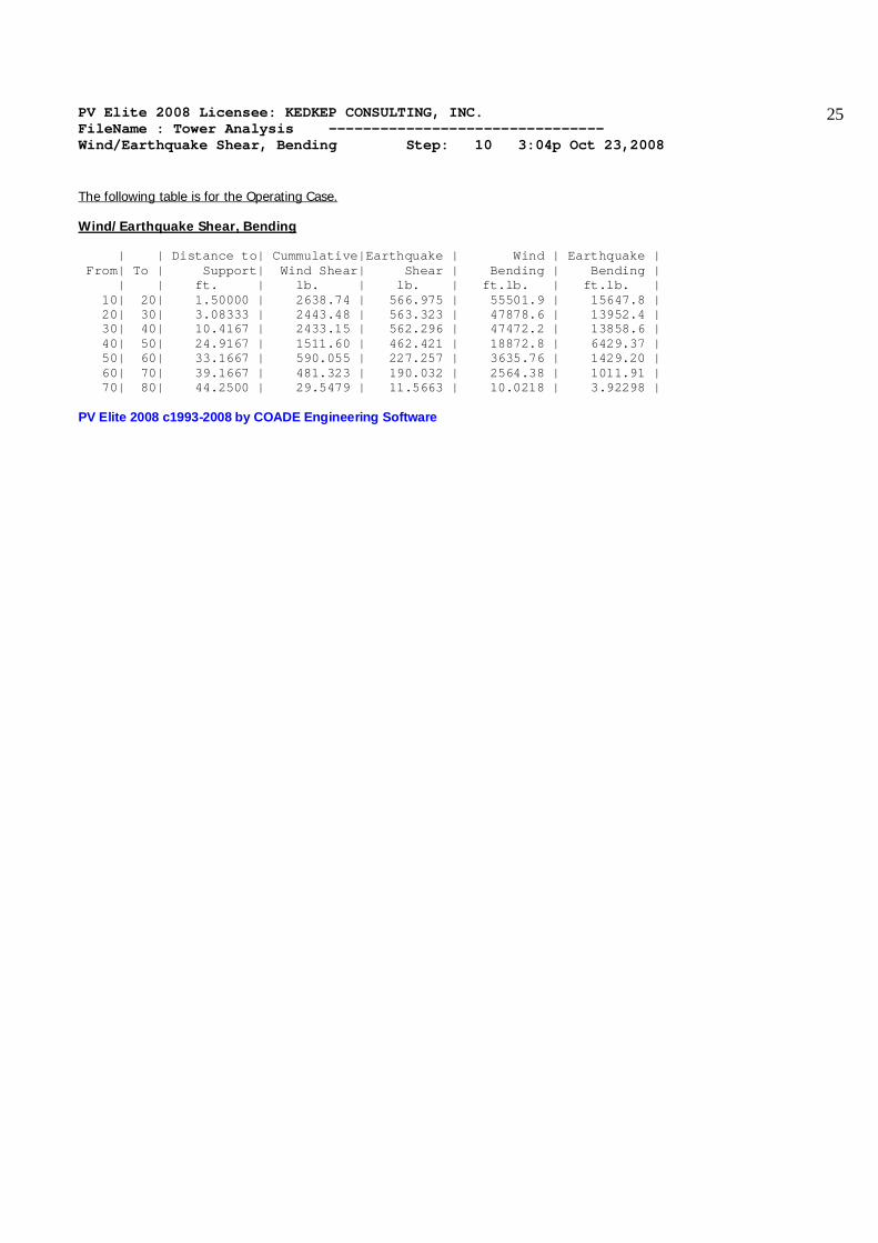
The following table is for the Operating Case. Wind/Earthquake Shear, Bending | | Distance to| Cummulative|Earthquake | Wind | Earthquake | From| To | Support| Wind Shear| Shear | Bending | Bending | | | ft. | lb. | lb. | ft.lb. | ft.lb. | 10| 20| 1.50000 | 2638.74 | 566.975 | 55501.9 | 15647.8 | 20| 30| 3.08333 | 2443.48 | 563.323 | 47878.6 | 13952.4 | 30| 40| 10.4167 | 2433.15 | 562.296 | 47472.2 | 13858.6 | 40| 50| 24.9167 | 1511.60 | 462.421 | 18872.8 | 6429.37 | 50| 60| 33.1667 | 590.055 | 227.257 | 3635.76 | 1429.20 | 60| 70| 39.1667 | 481.323 | 190.032 | 2564.38 | 1011.91 | 70| 80| 44.2500 | 29.5479 | 11.5663 | 10.0218 | 3.92298 | PV Elite 2008 c1993-2008 by COADE Engineering Software

PV Elite 2008 Licensee: KEDKEP CONSULTING, INC. FileName : Tower Analysis -------------------------------- Wind Deflection Step: 11 3:04p Oct 23,2008
26
Wind Deflection Calculations: The following table is for the Operating Case. Wind Deflection | | Cumulative | Centroid | Elem. End | Elem. Ang. | From| To | Wind Shear | Deflection |Deflection | Rotation | | | lb. | in. | in. | | 10| 20| 2638.74 | 0.00025070 |0.00097905 | 0.00005 | 20| 30| 2443.48 | 0.0010352 | 0.0010975 | 0.00007 | 30| 40| 2433.15 | 0.010709 | 0.026282 | 0.00020358 | 40| 50| 1511.60 | 0.045447 | 0.066462 | 0.00024730 | 50| 60| 590.055 | 0.069435 | 0.072420 | 0.00024913 | 60| 70| 481.323 | 0.087603 | 0.10299 | 0.00025681 | 70| 80| 29.5479 | 0.10325 | 0.10351 | 0.00025681 | Critical Wind Velocity for Tower Vibration | | 1st Crit. | 2nd Crit. | From| To | Wind Speed | Wind Speed | | | mile/hr | mile/hr | 10| 20| 67.6836 | 423.022 | 20| 30| 64.4985 | 403.115 | 30| 40| 66.0910 | 413.069 | 40| 50| 66.0910 | 413.069 | 50| 60| 56.5357 | 353.348 | 60| 70| 46.9804 | 293.627 | 70| 80| 45.7859 | 286.162 | Allowable deflection at the Tower Top (Ope)( 6.000"/100ft. Criteria) Allowable deflection : 2.660 Actual Deflection : 0.104 in. PV Elite 2008 c1993-2008 by COADE Engineering Software

PV Elite 2008 Licensee: KEDKEP CONSULTING, INC. FileName : Tower Analysis -------------------------------- Longitudinal Stress Constants Step: 12 3:04p Oct 23,2008
27
Longitudinal Stress Constants | | Metal Area | Metal Area |New & Cold | Corroded | From| To | New & Cold | Corroded |Sect. Mod. | Sect. Mod. | | | sq.in. | sq.in. | in.3 | in.3 | 10| 20| 65.9734 | 65.9734 | 684.669 | 684.669 | 20| 30| 31.6123 | 15.8552 | 316.147 | 159.546 | 30| 40| 96.0149 | 80.2579 | 960.800 | 807.972 | 40| 50| 96.0149 | 80.2579 | 960.800 | 807.972 | 50| 60| 99.0260 | 82.7825 | 990.973 | 833.571 | 60| 70| 67.7406 | 56.6959 | 474.830 | 400.790 | 70| 80| 33.4285 | 22.3838 | 234.081 | 158.110 | PV Elite 2008 c1993-2008 by COADE Engineering Software

PV Elite 2008 Licensee: KEDKEP CONSULTING, INC. FileName : Tower Analysis -------------------------------- Longitudinal Allowable Stresses Step: 13 3:04p Oct 23,2008
28
Longitudinal Allowable Stresses | | All. Str. | All. Str. | All. Str. | All. Str. | From| To | Long. Ten. | Hydr. Ten. |Long. Com. | Hyr. Comp. | | | psi | psi | psi | psi | 10| 20| 16800.0 | 21840.0 | -19414.6 | -24268.3 | 20| 30| 16800.0 | 21840.0 | -13388.6 | -21215.5 | 30| 40| 16800.0 | 21840.0 | -20122.0 | -25704.1 | 40| 50| 16800.0 | 21840.0 | -20122.0 | -25704.1 | 50| 60| 16800.0 | 21840.0 | -20197.3 | -25784.5 | 60| 70| 16800.0 | 21840.0 | -20892.0 | -26505.8 | 70| 80| 16800.0 | 21840.0 | -18377.1 | -24656.9 | PV Elite 2008 c1993-2008 by COADE Engineering Software
PV Elite 2008 Licensee: KEDKEP CONSULTING, INC. FileName : Tower Analysis -------------------------------- Longitudinal Stresses Due to . . . Step: 14 3:04p Oct 23,2008
29
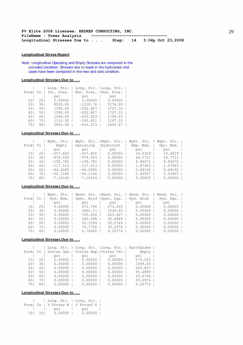
Longitudinal Stress Report Note: Longitudinal Operating and Empty Stresses are computed in the corroded condition. Stresses due to loads in the hydrostatic test cases have been computed in the new and cold condition. Longitudinal Stresses Due to . . . | | Long. Str. | Long. Str. |Long. Str. | From| To | Int. Pres. | Ext. Pres. |Hyd. Pres. | | | psi | psi | psi | 10| 20| 0.00000 | 0.00000 | 0.00000 | 20| 30| 8030.00 | -1218.76 | 5174.00 | 30| 40| 1590.00 | -252.807 | 1707.33 | 40| 50| 1590.00 | -252.807 | 1707.33 | 50| 60| 1589.69 | -253.203 | 1706.53 | 60| 70| 1110.00 | -180.831 | 1187.33 | 70| 80| 2805.00 | -435.033 | 2400.67 | Longitudinal Stresses Due to . . . | | Wght. Str. | Wght. Str. |Wght. Str. | Wght. Str. | Wght. Str. | From| To | Empty | Operating |Hydrotest | Emp. Mom. | Opr. Mom. | | | psi | psi | psi | psi | psi | 10| 20| -257.820 | -257.820 | 0.00000 | 10.4329 | 10.4329 | 20| 30| -978.593 | -978.593 | 0.00000 | 44.7711 | 44.7711 | 30| 40| -190.780 | -190.780 | 0.00000 | 8.84072 | 8.84072 | 40| 50| -117.513 | -117.513 | 0.00000 | 1.67963 | 1.67963 | 50| 60| -44.0085 | -44.0085 | 0.00000 | 0.69192 | 0.69192 | 60| 70| -52.1166 | -52.1166 | 0.00000 | 1.43907 | 1.43907 | 70| 80| -7.16164 | -7.16164 | 0.00000 | 0.00000 | 0.00000 | Longitudinal Stresses Due to . . . | | Wght. Str. | Bend. Str. |Bend. Str. | Bend. Str. | Bend. Str. | From| To | Hyd. Mom. | Oper. Wind |Oper. Equ. | Hyd. Wind | Hyd. Equ. | | | psi | psi | psi | psi | psi | 10| 20| 0.00000 | 972.766 | 274.255 | 0.00000 | 0.00000 | 20| 30| 0.00000 | 3601.11 | 1049.40 | 0.00000 | 0.00000 | 30| 40| 0.00000 | 705.056 | 205.827 | 0.00000 | 0.00000 | 40| 50| 0.00000 | 280.298 | 95.4889 | 0.00000 | 0.00000 | 50| 60| 0.00000 | 52.3399 | 20.5746 | 0.00000 | 0.00000 | 60| 70| 0.00000 | 76.7796 | 30.2976 | 0.00000 | 0.00000 | 70| 80| 0.00000 | 0.76062 | 0.29774 | 0.00000 | 0.00000 | Longitudinal Stresses Due to . . . | | Long. Str. | Long. Str. |Long. Str. | EarthQuake | From| To | Vortex Ope.| Vortex Emp.|Vortex Tst.| Empty | | | psi | psi | psi | psi | 10| 20| 0.00000 | 0.00000 | 0.00000 | 274.255 | 20| 30| 0.00000 | 0.00000 | 0.00000 | 1049.40 | 30| 40| 0.00000 | 0.00000 | 0.00000 | 205.827 | 40| 50| 0.00000 | 0.00000 | 0.00000 | 95.4889 | 50| 60| 0.00000 | 0.00000 | 0.00000 | 20.5746 | 60| 70| 0.00000 | 0.00000 | 0.00000 | 30.2976 | 70| 80| 0.00000 | 0.00000 | 0.00000 | 0.29774 | Longitudinal Stresses Due to . . . | | Long. Str. | Long. Str. | From| To | Y Forces W | Y ForceS S | | | psi | psi | 10| 20| 0.00000 | 0.00000 |
PV Elite 2008 Licensee: KEDKEP CONSULTING, INC. FileName : Tower Analysis -------------------------------- Longitudinal Stresses Due to . . . Step: 14 3:04p Oct 23,2008
30
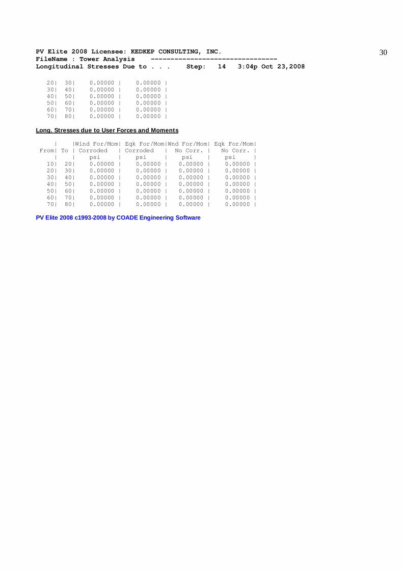
20| 30| 0.00000 | 0.00000 | 30| 40| 0.00000 | 0.00000 | 40| 50| 0.00000 | 0.00000 | 50| 60| 0.00000 | 0.00000 | 60| 70| 0.00000 | 0.00000 | 70| 80| 0.00000 | 0.00000 | Long. Stresses due to User Forces and Moments | |Wind For/Mom| Eqk For/Mom|Wnd For/Mom| Eqk For/Mom| From| To | Corroded | Corroded | No Corr. | No Corr. | | | psi | psi | psi | psi | 10| 20| 0.00000 | 0.00000 | 0.00000 | 0.00000 | 20| 30| 0.00000 | 0.00000 | 0.00000 | 0.00000 | 30| 40| 0.00000 | 0.00000 | 0.00000 | 0.00000 | 40| 50| 0.00000 | 0.00000 | 0.00000 | 0.00000 | 50| 60| 0.00000 | 0.00000 | 0.00000 | 0.00000 | 60| 70| 0.00000 | 0.00000 | 0.00000 | 0.00000 | 70| 80| 0.00000 | 0.00000 | 0.00000 | 0.00000 | PV Elite 2008 c1993-2008 by COADE Engineering Software

PV Elite 2008 Licensee: KEDKEP CONSULTING, INC. FileName : Tower Analysis -------------------------------- Stress due to Combined Loads Step: 15 3:04p Oct 23,2008
31
Stress Combination Load Cases for Vertical Vessels: Load Case Definition Key IP = Longitudinal Stress due to Internal Pressure EP = Longitudinal Stress due to External Pressure HP = Longitudinal Stress due to Hydrotest Pressure NP = No Pressure EW = Longitudinal Stress due to Weight (No Liquid) OW = Longitudinal Stress due to Weight (Operating) HW = Longitudinal Stress due to Weight (Hydrotest) WI = Bending Stress due to Wind Moment (Operating) EQ = Bending Stress due to Earthquake Moment (Operating) EE = Bending Stress due to Earthquake Moment (Empty) HI = Bending Stress due to Wind Moment (Hydrotest) HE = Bending Stress due to Earthquake Moment (Hydrotest) WE = Bending Stress due to Wind Moment (Empty) (no CA) WF = Bending Stress due to Wind Moment (Filled) (no CA) CW = Longitudinal Stress due to Weight (Empty) (no CA) VO = Bending Stress due to Vortex Shedding Loads ( Ope ) VE = Bending Stress due to Vortex Shedding Loads ( Emp ) VF = Bending Stress due to Vortex Shedding Loads ( Test No CA. ) FW = Axial Stress due to Vertical Forces for the Wind Case FS = Axial Stress due to Vertical Forces for the Seismic Case BW = Bending Stress due to Lat. Forces for the Wind Case, Corroded BS = Bending Stress due to Lat. Forces for the Seismic Case, Corroded BN = Bending Stress due to Lat. Forces for the Wind Case, UnCorroded BU = Bending Stress due to Lat. Forces for the Seismic Case, UnCorroded General Notes: Case types HI and HE are in the Un-Corroded condition. Case types WE, WF, and CW are in the Un-Corroded condition. A blank stress and stress ratio indicates that the corresponding stress comprising those components that did not contribute to that type of stress. An asterisk (*) in the final column denotes overstress. Analysis of Load Case 1 : NP+EW+WI+FW+BW From Tensile All. Tens. Comp. All. Comp. Tens. Comp. Node Stress Stress Stress Stress Ratio Ratio 10 725.38 16800.00 -1241.02 -19414.62 0.0432 0.0639 20 2667.28 16800.00 -4624.47 -13388.63 0.1588 0.3454 30 523.12 16800.00 -904.68 -20122.00 0.0311 0.0450 40 164.46 16800.00 -399.49 -20122.00 0.0098 0.0199 50 9.02 16800.00 -97.04 -20197.31 0.0005 0.0048 60 26.10 16800.00 -130.34 -20892.02 0.0016 0.0062 70 16800.00 -7.92 -18377.09 0.0004 Analysis of Load Case 2 : NP+EW+EE+FS+BS From Tensile All. Tens. Comp. All. Comp. Tens. Comp. Node Stress Stress Stress Stress Ratio Ratio 10 26.87 16800.00 -542.51 -19414.62 0.0016 0.0279 20 115.58 16800.00 -2072.77 -13388.63 0.0069 0.1548 30 23.89 16800.00 -405.45 -20122.00 0.0014 0.0201 40 16800.00 -214.68 -20122.00 0.0107 50 16800.00 -65.28 -20197.31 0.0032 60 16800.00 -83.85 -20892.02 0.0040 70 16800.00 -7.46 -18377.09 0.0004
PV Elite 2008 Licensee: KEDKEP CONSULTING, INC. FileName : Tower Analysis -------------------------------- Stress due to Combined Loads Step: 15 3:04p Oct 23,2008
32
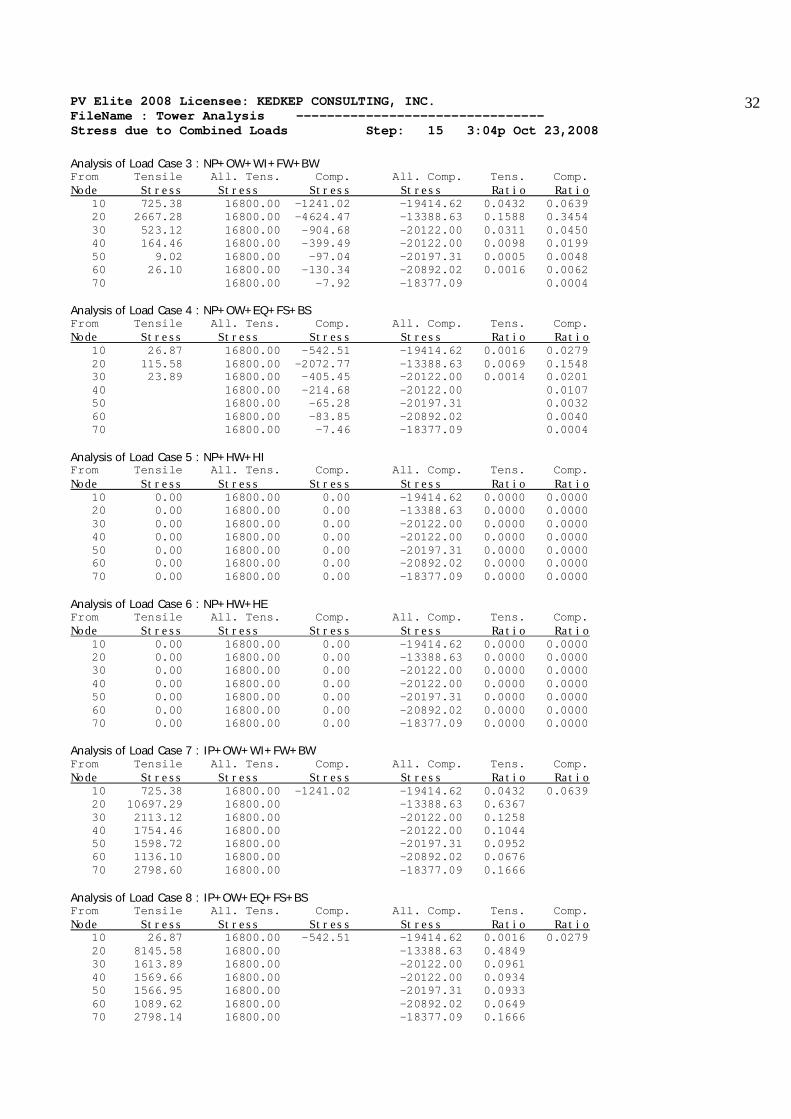
Analysis of Load Case 3 : NP+OW+WI+FW+BW From Tensile All. Tens. Comp. All. Comp. Tens. Comp. Node Stress Stress Stress Stress Ratio Ratio 10 725.38 16800.00 -1241.02 -19414.62 0.0432 0.0639 20 2667.28 16800.00 -4624.47 -13388.63 0.1588 0.3454 30 523.12 16800.00 -904.68 -20122.00 0.0311 0.0450 40 164.46 16800.00 -399.49 -20122.00 0.0098 0.0199 50 9.02 16800.00 -97.04 -20197.31 0.0005 0.0048 60 26.10 16800.00 -130.34 -20892.02 0.0016 0.0062 70 16800.00 -7.92 -18377.09 0.0004 Analysis of Load Case 4 : NP+OW+EQ+FS+BS From Tensile All. Tens. Comp. All. Comp. Tens. Comp. Node Stress Stress Stress Stress Ratio Ratio 10 26.87 16800.00 -542.51 -19414.62 0.0016 0.0279 20 115.58 16800.00 -2072.77 -13388.63 0.0069 0.1548 30 23.89 16800.00 -405.45 -20122.00 0.0014 0.0201 40 16800.00 -214.68 -20122.00 0.0107 50 16800.00 -65.28 -20197.31 0.0032 60 16800.00 -83.85 -20892.02 0.0040 70 16800.00 -7.46 -18377.09 0.0004 Analysis of Load Case 5 : NP+HW+HI From Tensile All. Tens. Comp. All. Comp. Tens. Comp. Node Stress Stress Stress Stress Ratio Ratio 10 0.00 16800.00 0.00 -19414.62 0.0000 0.0000 20 0.00 16800.00 0.00 -13388.63 0.0000 0.0000 30 0.00 16800.00 0.00 -20122.00 0.0000 0.0000 40 0.00 16800.00 0.00 -20122.00 0.0000 0.0000 50 0.00 16800.00 0.00 -20197.31 0.0000 0.0000 60 0.00 16800.00 0.00 -20892.02 0.0000 0.0000 70 0.00 16800.00 0.00 -18377.09 0.0000 0.0000 Analysis of Load Case 6 : NP+HW+HE From Tensile All. Tens. Comp. All. Comp. Tens. Comp. Node Stress Stress Stress Stress Ratio Ratio 10 0.00 16800.00 0.00 -19414.62 0.0000 0.0000 20 0.00 16800.00 0.00 -13388.63 0.0000 0.0000 30 0.00 16800.00 0.00 -20122.00 0.0000 0.0000 40 0.00 16800.00 0.00 -20122.00 0.0000 0.0000 50 0.00 16800.00 0.00 -20197.31 0.0000 0.0000 60 0.00 16800.00 0.00 -20892.02 0.0000 0.0000 70 0.00 16800.00 0.00 -18377.09 0.0000 0.0000 Analysis of Load Case 7 : IP+OW+WI+FW+BW From Tensile All. Tens. Comp. All. Comp. Tens. Comp. Node Stress Stress Stress Stress Ratio Ratio 10 725.38 16800.00 -1241.02 -19414.62 0.0432 0.0639 20 10697.29 16800.00 -13388.63 0.6367 30 2113.12 16800.00 -20122.00 0.1258 40 1754.46 16800.00 -20122.00 0.1044 50 1598.72 16800.00 -20197.31 0.0952 60 1136.10 16800.00 -20892.02 0.0676 70 2798.60 16800.00 -18377.09 0.1666 Analysis of Load Case 8 : IP+OW+EQ+FS+BS From Tensile All. Tens. Comp. All. Comp. Tens. Comp. Node Stress Stress Stress Stress Ratio Ratio 10 26.87 16800.00 -542.51 -19414.62 0.0016 0.0279 20 8145.58 16800.00 -13388.63 0.4849 30 1613.89 16800.00 -20122.00 0.0961 40 1569.66 16800.00 -20122.00 0.0934 50 1566.95 16800.00 -20197.31 0.0933 60 1089.62 16800.00 -20892.02 0.0649 70 2798.14 16800.00 -18377.09 0.1666

PV Elite 2008 Licensee: KEDKEP CONSULTING, INC. FileName : Tower Analysis -------------------------------- Stress due to Combined Loads Step: 15 3:04p Oct 23,2008
33
Analysis of Load Case 9 : EP+OW+WI+FW+BW From Tensile All. Tens. Comp. All. Comp. Tens. Comp. Node Stress Stress Stress Stress Ratio Ratio 10 725.38 16800.00 -1241.02 -19414.62 0.0432 0.0639 20 1448.52 16800.00 -5843.23 -13388.63 0.0862 0.4364 30 270.31 16800.00 -1157.48 -20122.00 0.0161 0.0575 40 16800.00 -652.30 -20122.00 0.0324 50 16800.00 -350.24 -20197.31 0.0173 60 16800.00 -311.17 -20892.02 0.0149 70 16800.00 -442.96 -18377.09 0.0241 Analysis of Load Case 10 : EP+OW+EQ+FS+BS From Tensile All. Tens. Comp. All. Comp. Tens. Comp. Node Stress Stress Stress Stress Ratio Ratio 10 26.87 16800.00 -542.51 -19414.62 0.0016 0.0279 20 16800.00 -3291.53 -13388.63 0.2458 30 16800.00 -658.25 -20122.00 0.0327 40 16800.00 -467.49 -20122.00 0.0232 50 16800.00 -318.48 -20197.31 0.0158 60 16800.00 -264.68 -20892.02 0.0127 70 16800.00 -442.49 -18377.09 0.0241 Analysis of Load Case 11 : HP+HW+HI From Tensile All. Tens. Comp. All. Comp. Tens. Comp. Node Stress Stress Stress Stress Ratio Ratio 10 0.00 21840.00 0.00 -24268.28 0.0000 0.0000 20 5174.00 21840.00 -21215.53 0.2369 30 1707.33 21840.00 -25704.14 0.0782 40 1707.33 21840.00 -25704.14 0.0782 50 1706.53 21840.00 -25784.51 0.0781 60 1187.33 21840.00 -26505.81 0.0544 70 2400.67 21840.00 -24656.91 0.1099 Analysis of Load Case 12 : HP+HW+HE From Tensile All. Tens. Comp. All. Comp. Tens. Comp. Node Stress Stress Stress Stress Ratio Ratio 10 0.00 21840.00 0.00 -24268.28 0.0000 0.0000 20 5174.00 21840.00 -21215.53 0.2369 30 1707.33 21840.00 -25704.14 0.0782 40 1707.33 21840.00 -25704.14 0.0782 50 1706.53 21840.00 -25784.51 0.0781 60 1187.33 21840.00 -26505.81 0.0544 70 2400.67 21840.00 -24656.91 0.1099 Analysis of Load Case 13 : IP+WE+EW From Tensile All. Tens. Comp. All. Comp. Tens. Comp. Node Stress Stress Stress Stress Ratio Ratio 10 16800.00 -268.25 -19414.62 0.0138 20 7096.18 16800.00 -13388.63 0.4224 30 1408.06 16800.00 -20122.00 0.0838 40 1474.17 16800.00 -20122.00 0.0877 50 1546.38 16800.00 -20197.31 0.0920 60 1059.32 16800.00 -20892.02 0.0631 70 2797.84 16800.00 -18377.09 0.1665 Analysis of Load Case 14 : IP+WF+CW From Tensile All. Tens. Comp. All. Comp. Tens. Comp. Node Stress Stress Stress Stress Ratio Ratio 10 16800.00 -257.82 -19414.62 0.0133 20 7539.18 16800.00 -13388.63 0.4488 30 1430.53 16800.00 -20122.00 0.0852 40 1491.77 16800.00 -20122.00 0.0888 50 1552.90 16800.00 -20197.31 0.0924 60 1066.38 16800.00 -20892.02 0.0635
PV Elite 2008 Licensee: KEDKEP CONSULTING, INC. FileName : Tower Analysis -------------------------------- Stress due to Combined Loads Step: 15 3:04p Oct 23,2008
34
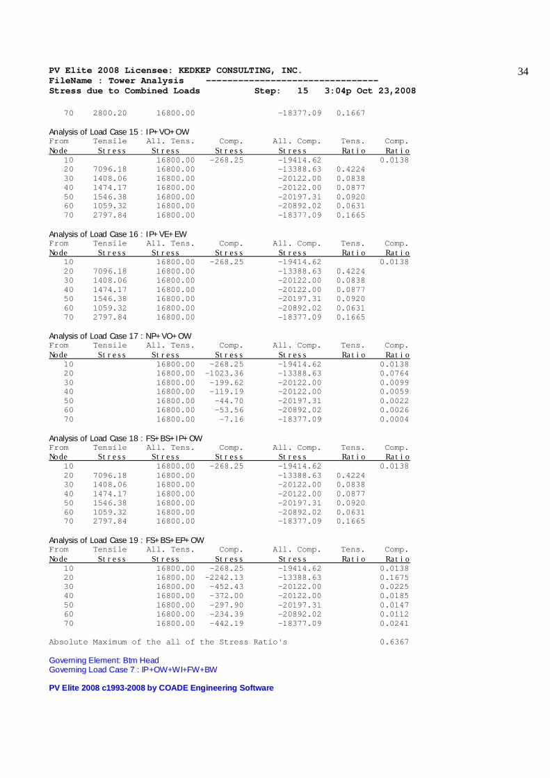
70 2800.20 16800.00 -18377.09 0.1667 Analysis of Load Case 15 : IP+VO+OW From Tensile All. Tens. Comp. All. Comp. Tens. Comp. Node Stress Stress Stress Stress Ratio Ratio 10 16800.00 -268.25 -19414.62 0.0138 20 7096.18 16800.00 -13388.63 0.4224 30 1408.06 16800.00 -20122.00 0.0838 40 1474.17 16800.00 -20122.00 0.0877 50 1546.38 16800.00 -20197.31 0.0920 60 1059.32 16800.00 -20892.02 0.0631 70 2797.84 16800.00 -18377.09 0.1665 Analysis of Load Case 16 : IP+VE+EW From Tensile All. Tens. Comp. All. Comp. Tens. Comp. Node Stress Stress Stress Stress Ratio Ratio 10 16800.00 -268.25 -19414.62 0.0138 20 7096.18 16800.00 -13388.63 0.4224 30 1408.06 16800.00 -20122.00 0.0838 40 1474.17 16800.00 -20122.00 0.0877 50 1546.38 16800.00 -20197.31 0.0920 60 1059.32 16800.00 -20892.02 0.0631 70 2797.84 16800.00 -18377.09 0.1665 Analysis of Load Case 17 : NP+VO+OW From Tensile All. Tens. Comp. All. Comp. Tens. Comp. Node Stress Stress Stress Stress Ratio Ratio 10 16800.00 -268.25 -19414.62 0.0138 20 16800.00 -1023.36 -13388.63 0.0764 30 16800.00 -199.62 -20122.00 0.0099 40 16800.00 -119.19 -20122.00 0.0059 50 16800.00 -44.70 -20197.31 0.0022 60 16800.00 -53.56 -20892.02 0.0026 70 16800.00 -7.16 -18377.09 0.0004 Analysis of Load Case 18 : FS+BS+IP+OW From Tensile All. Tens. Comp. All. Comp. Tens. Comp. Node Stress Stress Stress Stress Ratio Ratio 10 16800.00 -268.25 -19414.62 0.0138 20 7096.18 16800.00 -13388.63 0.4224 30 1408.06 16800.00 -20122.00 0.0838 40 1474.17 16800.00 -20122.00 0.0877 50 1546.38 16800.00 -20197.31 0.0920 60 1059.32 16800.00 -20892.02 0.0631 70 2797.84 16800.00 -18377.09 0.1665 Analysis of Load Case 19 : FS+BS+EP+OW From Tensile All. Tens. Comp. All. Comp. Tens. Comp. Node Stress Stress Stress Stress Ratio Ratio 10 16800.00 -268.25 -19414.62 0.0138 20 16800.00 -2242.13 -13388.63 0.1675 30 16800.00 -452.43 -20122.00 0.0225 40 16800.00 -372.00 -20122.00 0.0185 50 16800.00 -297.90 -20197.31 0.0147 60 16800.00 -234.39 -20892.02 0.0112 70 16800.00 -442.19 -18377.09 0.0241 Absolute Maximum of the all of the Stress Ratio's 0.6367 Governing Element: Btm Head Governing Load Case 7 : IP+OW+WI+FW+BW PV Elite 2008 c1993-2008 by COADE Engineering Software

PV Elite 2008 Licensee: KEDKEP CONSULTING, INC. FileName : Tower Analysis -------------------------------- Center of Gravity Calculation Step: 16 3:04p Oct 23,2008
35
Shop/Field Installation Options : Note : The CG is computed from the first Element From Node Center of Gravity of Stiffening Rings 32.0 ft. Center of Gravity of Nozzles 13.3 ft. Center of Gravity of Bare Shell New and Cold 20.5 ft. Center of Gravity of Bare Shell Corroded 20.2 ft. Vessel CG in the Operating Condition 20.1 ft. Vessel CG in the Fabricated (Shop/Empty) Condition 20.4 ft. PV Elite 2008 c1993-2008 by COADE Engineering Software

PV Elite 2008 Licensee: KEDKEP CONSULTING, INC. FileName : Tower Analysis -------------------------------- Basering Calculations Step: 17 3:04p Oct 23,2008
36
Skirt Data : Skirt Outside Diameter at Base SOD 42.5000 in. Skirt Thickness STHK 0.5000 in. Skirt Internal Corrosion Allowance SCA 0.0000 in. Skirt External Corrosion Allowance 0.0000 in. Skirt Material SA-516 70 Basering Input: Type of Geometry: Basering W/Gussets & Chair Cap Thickness of Basering TBA 1.5000 in. Design Temperature of the Basering 100.00 F Basering Matl SA-516 70 Basering Operating All. Stress BASOPE 20000.00 psi Basering Yield Stress 38000.00 psi Inside Diameter of Basering DI 41.5000 in. Outside Diameter of Basering DOU 51.5000 in. Nominal Diameter of Bolts BND 2.0000 in. Bolt Corrosion Allowance BCA 0.0000 in. Bolt Material SA-193 B7 Bolt Operating Allowable Stress SA 25000.00 psi Number of Bolts NGIV 8 Diameter of Bolt Circle DC 47.5000 in. Ultimate Comp. Strength of Concrete FPC 3000.0 psi Allowable Comp. Strength of Concrete FC 1200.0 psi Modular ratio Steel/Concrete 9.833 Thickness of Gusset Plates TGA 0.7500 in. Width of Gussets at Top Plate TWDT 4.5000 in. Width of Gussets at Base Plate BWDT 4.5000 in. Gusset Plate Elastic Modulus E 28884600.0 psi Gusset Plate Yield Stress SY 38000.0 psi Height of Gussets HG 9.0000 in. Distance between Gussets RG 3.5000 in. Dist. from Bolt Center to Gusset (Rg/2) CG 1.7500 in. Number of Gussets per bolt NG 2 Thickness of Top Plate or Ring TTA 1.7500 in. Radial Width of the Top Plate TOPWTH 4.5000 in. Circum. Width of the Top Plate CMWTH 7.0000 in. Anchor Bolt Hole Dia. in Top Plate BHOLE 2.1250 in. External Corrosion Allowance CA 0.0000 in. Dead Weight of Vessel DW 17009.3 lb. Operating Weight of Vessel ROW 17009.3 lb. Earthquake Moment on Basering EQMOM 15647.8 ft.lb. Wind Moment on Basering WIMOM 55501.9 ft.lb. Percent Bolt Preload ppl 100.0 Use AISC A5.2 Increase in Fc and Bolt Stress No Use Allowable Weld Stress per AISC J2.5 No Factor for Increase of Allowables Fact 1.0000 Results for Basering Analysis : Analyze Option Calculation of Load per Bolt [W/Bolt], Wind + Dead Weight Condition: W = ROW M = WIMOM + UWIMOM = (( 4 * M/DC ) - W ) / RN per Jawad & Farr, Eq. 12.3 = (( 4 * 666022 / 47.500 ) - 17009 ) / 8 = 4884.6064 lb.
PV Elite 2008 Licensee: KEDKEP CONSULTING, INC. FileName : Tower Analysis -------------------------------- Basering Calculations Step: 17 3:04p Oct 23,2008
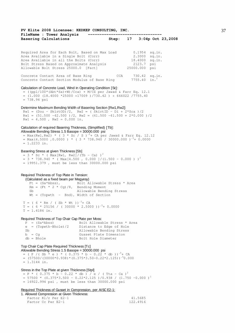
37
Required Area for Each Bolt, Based on Max Load 0.1954 sq.in. Area Available in a Single Bolt (Corr) 2.3000 sq.in. Area Available in all the Bolts (Corr) 18.4000 sq.in. Bolt Stress Based on Approximate Analysis 2123.7 psi Allowable Bolt Stress 25000.0 [Fact] 25000.000 psi Concrete Contact Area of Base Ring CCA 730.42 sq.in. Concrete Contact Section Modulus of Base Ring 7755.40 in.3 Calculation of Concrete Load, Wind in Operating Condition [Sc]: = ((ppl/100*(Abt*Sa)+W)/Cca) + M/CZ per Jawad & Farr Eq. 12.1 = (1.000 (18.4000 *25000 +17009 )/730.42 ) + 666022 /7755.40 = 738.94 psi Determine Maximum Bending Width of Basering Section [Rw1,Rw2]: Rw1 = (Dou - SkirtOD)/2, Rw2 = ( SkirtID - Di + 2*Sca )/2 Rw1 = (51.500 -42.500 )/2, Rw2 = (41.500 -41.500 + 2*0.000 )/2 Rw1 = 4.500 , Rw2 = 0.000 in. Calculation of required Basering Thickness, (Simplified) [Tb]: Allowable Bending Stress 1.5 Basope = 30000.000 psi = Max(Rw1,Rw2) * ( 3 * Sc / S ).5+ CA per Jawad & Farr Eq. 12.12 = Max(4.5000 ,0.0000 ) * ( 3 * 738.940 / 30000.000 ).5+ 0.0000 = 1.2233 in. Basering Stress at given Thickness [Sb] = 3 * Sc * ( Max[Rw1, Rw2]/(Tb - Ca) )2 = 3 * 738.940 * ( Max[4.500 , 0.000 ]/(1.500 - 0.000 ) )2 = 19951.379 , must be less than 30000.000 psi Required Thickness of Top Plate in Tension: (Calculated as a fixed beam per Megyesy) Ft = (Sa*Abss), Bolt Allowable Stress * Area Rm = (Ft * 2 * Cg)/8, Bending Moment Sb Allowable Bending Stress Wt = (Topwth - Bnd), Width of Section T = ( 6 * Rm / ( Sb * Wt )).5+ CA T = ( 6 * 25156 / ( 30000 * 2.5000 )).5+ 0.0000 T = 1.4186 in. Required Thickness of Top Chair Cap Plate per Moss: P = (Sa*Abss) Bolt Allowable Stress * Area e = (Topwth-Bhole)/2 Distance to Edge of Hole Sb Allowable Bending Stress b = Cg Gusset Plate Dimension db = Bhole Bolt Hole Diameter Top Chair Cap Plate Required Thickness [Tc] Allowable Bending Stress 1.5 Basope = 30000.000 psi = ( P /( Sb * e ) * ( 0.375 * b - 0.22 * db )).5+ CA = (57500/(30000*0.938)*(0.375*3.50-0.22*2.125)).50.000 = 1.3144 in. Stress in the Top Plate at given Thickness [Stpl] = P * ( 0.375 * b - 0.22 * db ) / e / ( Tta - Ca )2 = 57500 * (0.375*3.500 - 0.22*2.125 )/0.938 / (1.750 -0.000 )2 = 16922.994 psi , must be less than 30000.000 psi Required Thickness of Gusset in Compression, per AISC E2-1: 1. Allowed Compression at Given Thickness: Factor Kl/r Per E2-1 41.5685 Factor Cc Per E2-1 122.4916

PV Elite 2008 Licensee: KEDKEP CONSULTING, INC. FileName : Tower Analysis -------------------------------- Basering Calculations Step: 17 3:04p Oct 23,2008
38
Allowable Buckling Str. per E2-1 20017.37 psi Actual Buckling Str. at Given Thickness 8518.52 psi Required Gusset thickness, + CA 0.3977 in. 2. Allowed Compression at Calculated Thickness: Factor Kl/r Per E2-1 78.3862 Factor Cc Per E2-1 122.4916 Allowable Buckling Str. per E2-1 16126.55 psi Act. Buckling Str. at Calculated Thickness 16063.46 psi Summary of Basering Thickness Calculations: Required Basering Thickness (simplified) 1.2233 in. Actual Basering Thickness as entered by user 1.5000 in. Required Top Ring/Plate Thickness as a Fixed Beam 1.4186 in. Required Thickness of Chair Cap per Moss/AISI 1.3144 in. Actual Top Ring Thickness as entered by user 1.7500 in. Required Gusset thickness, + CA 0.3977 in. Actual Gusset Thickness as entered by user 0.7500 in. Local Stress at the Top Plate per AISI, including axial Stress [S]: = Wmax*e/t2 [1.32*Z/(1.43*Cmwth*(Hg+Tta)2/(R*Tskirt) + (4(Cmwth)(Hg+Tta)2).333 + 0.031 /(R*Tskirt).5 = 4884*2.50/0.502 [1.32*0.16/(1.43*7.00*(9.75)2/(20.75*0.50) + (4*7.00 (9.00 +0.75 )2).333 + 0.031/(20.75 *0.50 ).5 = 552.549 psi Where: Z = 1/[(0.177*Wgp*Tba/(R*t).5*(Tba/t)2 + 1] Z = 1/[(0.177*7.000*1.500/(20.750*0.500).5*(1.500/0.500)2+1] Z = 0.161 e = ( Dc - Ds ) / 2 e = ( 47.500 - 42.500 ) / 2 e = 2.500 in. Local Stress in the Skirt due to the Gussets 552 psi Weight plus Bending Stress in the Skirt (Highest) 1241 psi Comb. loc. + bending stress Worst Load Case 1793 psi Allowed membrane+bending stress( 1.5* Skirt All.) 30000 psi Weld Size Calculations per Steel Plate Engineering Data - Vol. 2 Compute the Weld load at the Skirt/Base Junction [W] = SkirtStress * ( SkirtThickness - CA ) = 1241.019 * ( 0.500 - 0.000 ) = 620.51 lb./in. Results for Computed Minimum Basering Weld Size [BWeld] = W / [( 0.4 * Yield ) * 2 * 0.707] = 620 / [( 0.4 * 34800 ) * 2 * 0.707] = 0.032 in. Results for Computed Minimum Gusset and Top Plate to Skirt Weld Size Vertical Plate Load [Wv] = Bolt Load / ( Cmwth + 2 * ( Hg + Tta ) ) = 57500.0 / ( 5.000 + 2 * ( 9.000 + 1.750 ) ) = 2169.811 lb./in. Horizontal Plate Load [Wh] = Bolt Load * e / ( Cmwth * (Hg+Tta) + 0.6667 * (Hg+Tta)2 )

PV Elite 2008 Licensee: KEDKEP CONSULTING, INC. FileName : Tower Analysis -------------------------------- Basering Calculations Step: 17 3:04p Oct 23,2008
39
= 57500.0 * 2.500 /(5.000 * (10.750 ) + 0.6667 * (10.750 )2 ) = 1099.073 lb./in. Resultant Weld Load [Wr] = ( Wv2 + Wh2).5 = ( 2169.812 + 1099.072).5 = 2432.292 lb./in. Results for Computed Min Gusset and Top Plate to Skirt Weld Size [GsWeld] = Wr / [( 0.4 * Yield ) * 2 * 0.707] = 2432.29 / [( 0.4 * 34800 ) * 2 * 0.707] = 0.124 in. Results for Computed Minimum Gusset to Top Plate Weld Size Weld Load [Wv] = Bolt Load / ( 2 * TopWth ) = 57500.0 / ( 2 * 4.500 ) = 6388.889 lb./in. Weld Load [Wh] = Bolt Load * e / ( 2 * Hgt * TopWth ) = 57500.0 * 2.50 / ( 2 * 10.750 * 4.500 ) = 1485.788 lb./in. Resultant Weld Load [Wr] = ( Wv2 + Wh2).5 = ( 6388.892 + 1485.792).5 = 6559.380 lb./in. Results for Computed Min Gusset to Top Plate Weld Size [GtpWeld] = Wr / [( 0.4 * Yield ) * 2 * 0.707] = 6559.38 / [( 0.4 * 34800 ) * 2 * 0.707] = 0.333 in. Note: The calculated weld sizes need not exceed the component thickness framing into the weld. At the same time, the weld must meet a minimum size specification which is 3/16 in. (4.76 mm) or 1/4 in. (6.35 mm), depending on the component thickness. Summary of Required Weld Sizes: Required Basering to Skirt Double Fillet Weld Size 0.1875 in. Required Gusset to Skirt Double Fillet Weld Size 0.2500 in. Required Top Plate to Skirt Weld Size 0.3333 in. Required Gusset to Top Plate Double Fillet Weld Size 0.3333 in. PV Elite 2008 c1993-2008 by COADE Engineering Software

PV Elite 2008 Licensee: KEDKEP CONSULTING, INC. FileName : Tower Analysis -------------------------------- Conical Section
40
Conical Reinforcement Calculations, ASME VIII Div. 1, App. 1 Conical Section From 50 To 60 SA-516 70 Cone Elastic Modulus Data from Table TM-1 at 200.00 F Elastic Modulus for Cone Material 28500000.00 psi Elastic Modulus for Small Cylinder Material 28500000.00 psi Elastic Modulus for Large Cylinder Material 28500000.00 psi Elastic Modulus for Large End Reinforcement 28500000.00 psi Elastic Modulus for Small End Reinforcement 28500000.00 psi Axial Force on Small End of Cone 2954.80 lb. Axial Force on Large End of Cone 3643.13 lb. Moment on Small End of Cone 2612.44 ft.lb. Moment on Large End of Cone 3683.82 ft.lb. Note: Both ends of the Cone are Lines of Support Maximum Centroid Reinforcement Distance Large End 0.9003 in. Maximum Centroid Reinforcement Distance Small End 0.7591 in. Note: No ring was found close enough to the large end to be considered. Note: No ring was found close enough to the small end to be considered. Reinforcement Calculations for Cone / Large Cylinder: Required Area of Reinforcement for Large End Under Internal Pressure Large end ratio of pressure to allowable stress 0.00588 Large end max. half apex angle w/o reinforcement 24.765 degrees Large end actual half apex angle 14.036 degrees Required Area of Reinforcement for Large End Under External Pressure Large end ratio of pressure to allowable stress 0.00088 Large end max. half apex angle w/o reinforcement 2.206 degrees Large end actual half apex angle 14.036 degrees Area of Reinforcement Required in Large End Shell [Arl]: = (k*Ql*Rl*tan(angle)/(Ss*E1))*(1-0.25*((P*Rl-Ql)/Ql)*(delta/alpha) = (1.0000*217.9774*20.7500*0.250/(20000*0.85))* (1-.25*((15.00*20.750-217.977)/217.977)*(2.206/14.036) = 0.0654 sq.in. Area of Reinforcement Available in Large End Shell [Ael]: = .55*( Dl*ts ).5* ( ts + tc/Cos(alpha) ) = .55 * ( 41.500 * 0.625 ).5* ( 0.625 + 0.625 / 0.970 ) = 3.5552 sq.in. Summary of Reinforcement Area, Large End, External Pressure: Area of reinforcement required per App. 1-8(1) 0.0654 sq.in. Area of reinforcement in shell per App. 1-8(2) 3.5552 sq.in. Area of reinforcement in stiffening ring 0.0000 sq.in. Intermediate Results, Large End, External Pressure: Area Available in Cone, Shell, and Reinforcement 8.48 sq.in. Force per Unit Length on Shell / Cone Junction 199.55 lb./in. Actual Buckling Stress associated with this Force 732.36 psi Material Strain associated with this stress 0.000051 Required Moment of Inertia, Large End, External Pressure [I's]: = A * Dl2 * Atl / 10.9

PV Elite 2008 Licensee: KEDKEP CONSULTING, INC. FileName : Tower Analysis -------------------------------- Conical Section
41
= 0.000051 * 41.5000 * 41.5000 * 8.48 / 10.9 = 0.07 in.4 Available Moment of Inertia, Large End, External Pressure: Area Centroid Ar*Ce Dist I Ar*Di2 Shl 1.500 0.0000 0.000 -0.1912 0.049 0.055 Con 1.805 -0.3501 -0.632 0.1589 0.136 0.046 Sec 0.000 0.3125 0.000 -0.5037 0.000 0.000 TOT 3.305 -0.632 0.185 0.100 Centroid of Section -0.1912 Moment of Inertia 0.29 Summary of Large End Inertia Calculations Available Moment of Inertia ( Large End ) 0.285 in**4 Required Moment of Inertia ( Large End ) 0.068 in**4 Reinforcement Calculations for Cone / Small Cylinder: Required Area of Reinforcement for Small End under Internal Pressure Small end ratio of pressure to allowable stress 0.00588 Small end max. half apex angle w/o reinforcement 6.529 degrees Small end actual half apex angle 14.036 degrees Required Area of Reinforcement, Small End, Internal [Ars]: = k*Qs*Rs/(Ss*E1)*(1-delta/alpha)*tan(alpha) = 1.00 * 720.9971 * 14.1250 / ( 20000 * 0.85 ) * ( 1.0 - 6.53 / 14.04 ) * 0.2500 = 0.0801 sq.in. Area of Reinforcement Available in Small End Shell [Aes]: = .78*(Rs*Ts).5 ((Ts-t)+(Tc-Tr)/Cos(alpha) )) = .78*(14.125 *0.625 ).5 (( 0.625 -0.083 )+( 0.625 -0.086 )/0.97 )) = 2.5430 sq.in. Summary of Reinforcement Area, Small End, Internal Pressure: Area of reinforcement required per App. 1-5(3) 0.0801 sq.in. Area of reinforcement in shell per App. 1-5(4) 2.5430 sq.in. Area of reinforcement in stiffening ring 0.0000 sq.in. Required Area of Reinforcement for Small End Under External Pressure Area of Reinforcement Required in Small End Shell [Ars]: = k * Qs * Rs * tan(alpha) / ( Ss * E1 ) = (1.0000*191.6300*14.7500*0.2500/(20000*0.85)) = 0.0416 sq.in. Area of Reinforcement Available in Small End Shell [Aes]: = .55*(Ds*ts).5 [(ts-t)+(tc-tr)/cos(alpha))] = .55*(29.500*0.625).5 [(0.625-0.169)+(0.625-0.084)/0.970] = 2.3929 sq.in. Summary of Reinforcement Area, Small End, External Pressure: Area of reinforcement required per App. 1-8(1) 0.0416 sq.in. Area of reinforcement in shell per App. 1-8(2) 2.3929 sq.in. Area of reinforcement in stiffening ring 0.0000 sq.in. Intermediate Results, Small End, External Pressure: Area Available in Cone, Shell, and Reinforcement 46.58 sq.in. Force per Unit Length on Shell / Cone Junction 1124.00 lb./in. Actual Buckling Stress associated with this Force 533.83 psi Material Strain associated with this stress 0.000037 Required Moment of Inertia, Small End, External Pressure [I's]: = A * Ds2 * Ats / 10.9 = 0.000037 * 29.5000 * 29.5000 * 46.58 / 10.9 = 0.14 in.4

PV Elite 2008 Licensee: KEDKEP CONSULTING, INC. FileName : Tower Analysis -------------------------------- Conical Section
42
Available Moment of Inertia, Small End, External Pressure: Area Centroid Ar*Ce Dist I Ar*Di2 Shl 1.476 0.0000 0.000 0.1498 0.048 0.033 Con 1.521 0.2952 0.449 -0.1454 0.097 0.032 Sec 0.000 0.3125 0.000 -0.1627 0.000 0.000 TOT 2.997 0.449 0.145 0.065 Centroid of Section 0.1498 Moment of Inertia 0.21 Summary of Small End Inertia Calculations Available Moment of Inertia ( Small End ) 0.210 in**4 Required Moment of Inertia ( Small End ) 0.137 in**4 Note: The following calculations are only required per 1-5(g)(1) and do include external loads due to wind or seismic. These discontinuity stresses are computed at the shell/cone junction and do not include effects of local stiffening from a junction ring. Results for Discontinuity Stresses per Bednar p. 236 2nd Edition Stress Type Stress Allowable Location Tensile Stress 2821.19 60000.00 Small Cyl. Long. Compres. Stress -462.23 -60000.00 Small Cyl. Long. Membrane Stress 3213.66 30000.00 Small End Tang. Tensile Stress 2857.49 60000.00 Cone Longitudinal Compres. Stress -425.93 -60000.00 Cone Longitudinal Tensile Stress 3284.76 30000.00 Cone Tangential Tensile Stress 4365.24 60000.00 Large Cyl. Long. Compres. Stress -1078.23 -60000.00 Large Cyl. Long. Membrane Stress 1870.12 -30000.00 Large End Tang. Tensile Stress 4415.82 60000.00 Cone Longitudinal Compres. Stress -1027.65 -60000.00 Cone Longitudinal Compres Stress 1970.76 -30000.00 Cone Tangential Note: An asterisk (*) denotes that this stress was not applicable for this combination of loads. PV Elite 2008 c1993-2008 by COADE Engineering Software
PV Elite 2008 Licensee: KEDKEP CONSULTING, INC. FileName : Tower Analysis -------------------------------- Nozzle Calcs. Drain Nozl: 1 3:04p Oct 23,2008
43
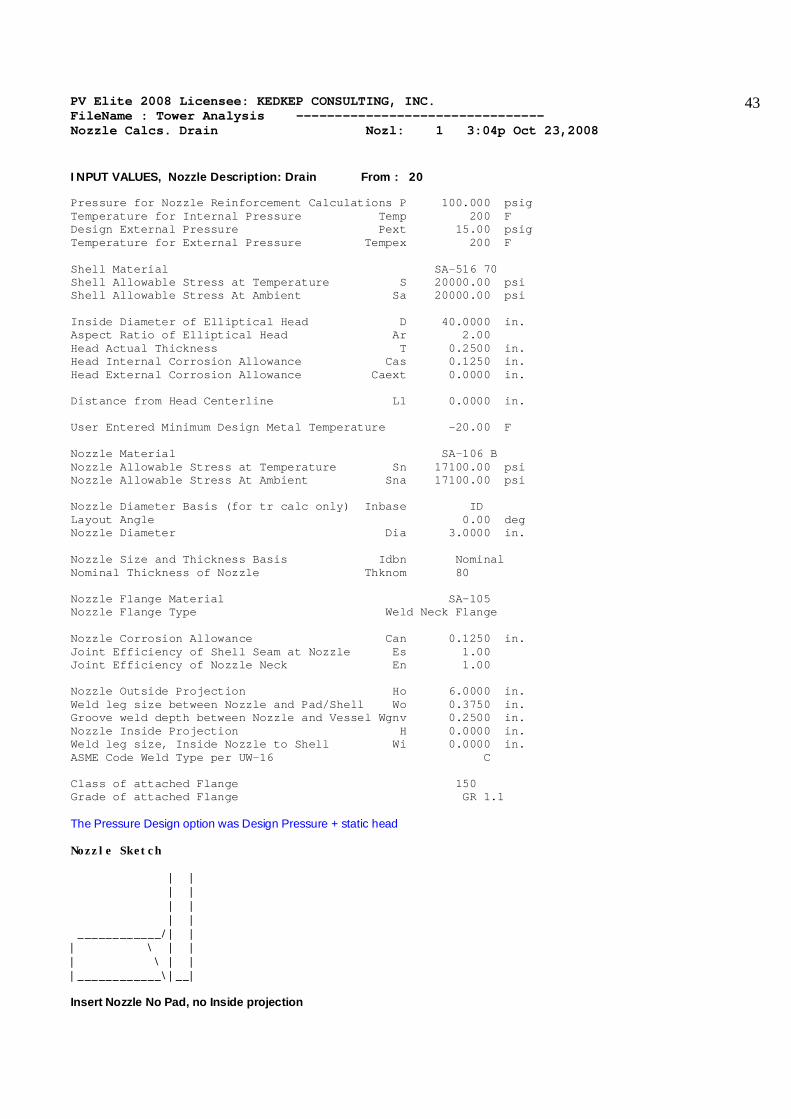
INPUT VALUES, Nozzle Description: Drain From : 20 Pressure for Nozzle Reinforcement Calculations P 100.000 psig Temperature for Internal Pressure Temp 200 F Design External Pressure Pext 15.00 psig Temperature for External Pressure Tempex 200 F Shell Material SA-516 70 Shell Allowable Stress at Temperature S 20000.00 psi Shell Allowable Stress At Ambient Sa 20000.00 psi Inside Diameter of Elliptical Head D 40.0000 in. Aspect Ratio of Elliptical Head Ar 2.00 Head Actual Thickness T 0.2500 in. Head Internal Corrosion Allowance Cas 0.1250 in. Head External Corrosion Allowance Caext 0.0000 in. Distance from Head Centerline L1 0.0000 in. User Entered Minimum Design Metal Temperature -20.00 F Nozzle Material SA-106 B Nozzle Allowable Stress at Temperature Sn 17100.00 psi Nozzle Allowable Stress At Ambient Sna 17100.00 psi Nozzle Diameter Basis (for tr calc only) Inbase ID Layout Angle 0.00 deg Nozzle Diameter Dia 3.0000 in. Nozzle Size and Thickness Basis Idbn Nominal Nominal Thickness of Nozzle Thknom 80 Nozzle Flange Material SA-105 Nozzle Flange Type Weld Neck Flange Nozzle Corrosion Allowance Can 0.1250 in. Joint Efficiency of Shell Seam at Nozzle Es 1.00 Joint Efficiency of Nozzle Neck En 1.00 Nozzle Outside Projection Ho 6.0000 in. Weld leg size between Nozzle and Pad/Shell Wo 0.3750 in. Groove weld depth between Nozzle and Vessel Wgnv 0.2500 in. Nozzle Inside Projection H 0.0000 in. Weld leg size, Inside Nozzle to Shell Wi 0.0000 in. ASME Code Weld Type per UW-16 C Class of attached Flange 150 Grade of attached Flange GR 1.1 The Pressure Design option was Design Pressure + static head Nozzle Sketch | | | | | | | | ____________/| | | \ | | | \ | | |____________\|__| Insert Nozzle No Pad, no Inside projection
PV Elite 2008 Licensee: KEDKEP CONSULTING, INC. FileName : Tower Analysis -------------------------------- Nozzle Calcs. Drain Nozl: 1 3:04p Oct 23,2008
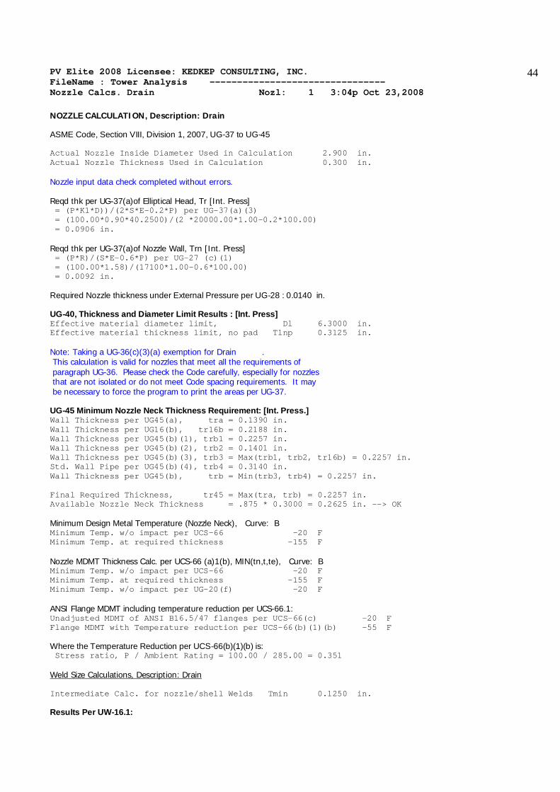
44
NOZZLE CALCULATION, Description: Drain ASME Code, Section VIII, Division 1, 2007, UG-37 to UG-45 Actual Nozzle Inside Diameter Used in Calculation 2.900 in. Actual Nozzle Thickness Used in Calculation 0.300 in. Nozzle input data check completed without errors. Reqd thk per UG-37(a)of Elliptical Head, Tr [Int. Press] = (P*K1*D))/(2*S*E-0.2*P) per UG-37(a)(3) = (100.00*0.90*40.2500)/(2 *20000.00*1.00-0.2*100.00) = 0.0906 in. Reqd thk per UG-37(a)of Nozzle Wall, Trn [Int. Press] = (P*R)/(S*E-0.6*P) per UG-27 (c)(1) = (100.00*1.58)/(17100*1.00-0.6*100.00) = 0.0092 in. Required Nozzle thickness under External Pressure per UG-28 : 0.0140 in. UG-40, Thickness and Diameter Limit Results : [Int. Press] Effective material diameter limit, Dl 6.3000 in. Effective material thickness limit, no pad Tlnp 0.3125 in. Note: Taking a UG-36(c)(3)(a) exemption for Drain . This calculation is valid for nozzles that meet all the requirements of paragraph UG-36. Please check the Code carefully, especially for nozzles that are not isolated or do not meet Code spacing requirements. It may be necessary to force the program to print the areas per UG-37. UG-45 Minimum Nozzle Neck Thickness Requirement: [Int. Press.] Wall Thickness per UG45(a), tra = 0.1390 in. Wall Thickness per UG16(b), tr16b = 0.2188 in. Wall Thickness per UG45(b)(1), trb1 = 0.2257 in. Wall Thickness per UG45(b)(2), trb2 = 0.1401 in. Wall Thickness per UG45(b)(3), trb3 = Max(trb1, trb2, tr16b) = 0.2257 in. Std. Wall Pipe per UG45(b)(4), trb4 = 0.3140 in. Wall Thickness per UG45(b), trb = Min(trb3, trb4) = 0.2257 in. Final Required Thickness, tr45 = Max(tra, trb) = 0.2257 in. Available Nozzle Neck Thickness = .875 * 0.3000 = 0.2625 in. --> OK Minimum Design Metal Temperature (Nozzle Neck), Curve: B Minimum Temp. w/o impact per UCS-66 -20 F Minimum Temp. at required thickness -155 F Nozzle MDMT Thickness Calc. per UCS-66 (a)1(b), MIN(tn,t,te), Curve: B Minimum Temp. w/o impact per UCS-66 -20 F Minimum Temp. at required thickness -155 F Minimum Temp. w/o impact per UG-20(f) -20 F ANSI Flange MDMT including temperature reduction per UCS-66.1: Unadjusted MDMT of ANSI B16.5/47 flanges per UCS-66(c) -20 F Flange MDMT with Temperature reduction per UCS-66(b)(1)(b) -55 F Where the Temperature Reduction per UCS-66(b)(1)(b) is: Stress ratio, P / Ambient Rating = 100.00 / 285.00 = 0.351 Weld Size Calculations, Description: Drain Intermediate Calc. for nozzle/shell Welds Tmin 0.1250 in. Results Per UW-16.1:

PV Elite 2008 Licensee: KEDKEP CONSULTING, INC. FileName : Tower Analysis -------------------------------- Nozzle Calcs. Drain Nozl: 1 3:04p Oct 23,2008
45
Required Thickness Actual Thickness Nozzle Weld 0.0875 = 0.7 * TMIN 0.2651 = 0.7 * Wo in. The Drop for this Nozzle is : 0.0423 in. The Cut Length for this Nozzle is, Drop + Ho + H + T : 6.2923 in. PV Elite 2008 c1993-2008 by COADE Engineering Software

PV Elite 2008 Licensee: KEDKEP CONSULTING, INC. FileName : Tower Analysis -------------------------------- Nozzle Calcs. Manway Nozl: 2 3:04p Oct 23,2008
46
INPUT VALUES, Nozzle Description: Manway From : 30 Pressure for Nozzle Reinforcement Calculations P 100.000 psig Temperature for Internal Pressure Temp 200 F Design External Pressure Pext 15.00 psig Temperature for External Pressure Tempex 200 F Shell Material SA-516 70 Shell Allowable Stress at Temperature S 20000.00 psi Shell Allowable Stress At Ambient Sa 20000.00 psi Inside Diameter of Cylindrical Shell D 40.0000 in. Design Length of Section L 350.9333 in. Shell Actual Thickness T 0.7500 in. Shell Internal Corrosion Allowance Cas 0.1250 in. Shell External Corrosion Allowance Caext 0.0000 in. Distance from Bottom/Left Tangent 3.1667 ft. User Entered Minimum Design Metal Temperature -20.00 F Nozzle Material SA-106 B Nozzle Allowable Stress at Temperature Sn 17100.00 psi Nozzle Allowable Stress At Ambient Sna 17100.00 psi Nozzle Diameter Basis (for tr calc only) Inbase ID Layout Angle 0.00 deg Nozzle Diameter Dia 16.0000 in. Nozzle Size and Thickness Basis Idbn Nominal Nominal Thickness of Nozzle Thknom 40 Nozzle Flange Material SA-105 Nozzle Flange Type Weld Neck Flange Nozzle Corrosion Allowance Can 0.1250 in. Joint Efficiency of Shell Seam at Nozzle Es 1.00 Joint Efficiency of Nozzle Neck En 1.00 Nozzle Outside Projection Ho 6.0000 in. Weld leg size between Nozzle and Pad/Shell Wo 0.3750 in. Groove weld depth between Nozzle and Vessel Wgnv 0.7500 in. Nozzle Inside Projection H 0.0000 in. Weld leg size, Inside Nozzle to Shell Wi 0.0000 in. ASME Code Weld Type per UW-16 None Class of attached Flange 150 Grade of attached Flange GR 1.1 The Pressure Design option was Design Pressure + static head Nozzle Sketch | | | | | | | | ____________/| | | \ | | | \ | | |____________\|__| Insert Nozzle No Pad, no Inside projection

PV Elite 2008 Licensee: KEDKEP CONSULTING, INC. FileName : Tower Analysis -------------------------------- Nozzle Calcs. Manway Nozl: 2 3:04p Oct 23,2008
47
NOZZLE CALCULATION, Description: Manway ASME Code, Section VIII, Division 1, 2007, UG-37 to UG-45 Actual Nozzle Inside Diameter Used in Calculation 15.000 in. Actual Nozzle Thickness Used in Calculation 0.500 in. Nozzle input data check completed without errors. Reqd thk per UG-37(a)of Cylindrical Shell, Tr [Int. Press] = (P*R)/(S*E-0.6*P) per UG-27 (c)(1) = (100.00*20.1250)/(20000*1.00-0.6*100.00) = 0.1009 in. Reqd thk per UG-37(a)of Nozzle Wall, Trn [Int. Press] = (P*R)/(S*E-0.6*P) per UG-27 (c)(1) = (100.00*7.62)/(17100*1.00-0.6*100.00) = 0.0447 in. Required Nozzle thickness under External Pressure per UG-28 : 0.0342 in. UG-40, Thickness and Diameter Limit Results : [Int. Press] Effective material diameter limit, Dl 30.5000 in. Effective material thickness limit, no pad Tlnp 0.9375 in. Results of Nozzle Reinforcement Area Calculations: AREA AVAILABLE, A1 to A5 Design External Mapnc Area Required Ar 1.550 2.420 NA sq.in. Area in Shell A1 7.935 4.692 NA sq.in. Area in Nozzle Wall A2 0.529 0.546 NA sq.in. Area in Inward Nozzle A3 0.000 0.000 NA sq.in. Area in Welds A4 0.120 0.120 NA sq.in. Area in Pad A5 0.000 0.000 NA sq.in. TOTAL AREA AVAILABLE Atot 8.585 5.359 NA sq.in. The External Pressure Case Governs the Analysis. Nozzle Angle Used in Area Calculations 90.00 Degs. The area available without a pad is Sufficient. Reinforcement Area Required for Nozzle [Ar]: = 0.5 * (DLR*Tr+2*Thk*Tr*(1-fr1)) per UG-37(d) or UG-39 = 0.5*(15.2500*0.3151+2*(0.5000-0.1250)*0.3151*(1-0.8550)) = 2.420 sq.in. Areas per UG-37.1 but with DL = Diameter Limit, DLR = Corroded ID: Area Available in Shell [A1]: = (DL-Dlr)*(ES*(T-Cas)-Tr)-2*(Thk-Can)*(ES*(T-Cas)-Tr)*(1-fr1) = (30.500-15.250)*(1.00*(0.7500-0.125)-0.315)-2*(0.500-0.125) *(1.00*(0.7500-0.1250)-0.3151)*(1-0.8550) = 4.692 sq.in. Area Available in Nozzle Wall, no Pad [A2np]: = ( 2 * min(Tlnp,ho) ) * ( Thk - Can - Trn ) * fr2 = ( 2 * min(0.938 ,6.000 ) ) * ( 0.5000 - 0.1250 - 0.0342 ) * 0.8550 ) = 0.546 sq.in. Area Available in Welds, no Pad [A4np]: = Wo2 * fr2 + ( Wi-Can/0.707 )2 * fr2 = 0.37502 * 0.8550 + ( 0.0000 )2 * 0.8550 = 0.120 sq.in. UG-45 Minimum Nozzle Neck Thickness Requirement: [Int. Press.]

PV Elite 2008 Licensee: KEDKEP CONSULTING, INC. FileName : Tower Analysis -------------------------------- Nozzle Calcs. Manway Nozl: 2 3:04p Oct 23,2008
48
Wall Thickness per UG45(a), tra = 0.1697 in. Wall Thickness per UG16(b), tr16b = 0.2188 in. Wall Thickness per UG45(b)(1), trb1 = 0.2259 in. Wall Thickness per UG45(b)(2), trb2 = 0.1401 in. Wall Thickness per UG45(b)(3), trb3 = Max(trb1, trb2, tr16b) = 0.2259 in. Std. Wall Pipe per UG45(b)(4), trb4 = 0.4531 in. Wall Thickness per UG45(b), trb = Min(trb3, trb4) = 0.2259 in. Final Required Thickness, tr45 = Max(tra, trb) = 0.2259 in. Available Nozzle Neck Thickness = .875 * 0.5000 = 0.4375 in. --> OK M.A.W.P. Results for this Nozzle (Based on Areas and UG-45) at this Location Approximate M.A.W.P. for given geometry 307.692 psig Nozzle is O.K. for the External Pressure 15.000 psig Note: The MAWP of this junction was limited by UG-45 considerations. Minimum Design Metal Temperature (Nozzle Neck), Curve: B Minimum Temp. w/o impact per UCS-66 -14 F Minimum Temp. at required thickness -154 F Minimum Temp. w/o impact per UG-20(f) -20 F Nozzle MDMT Thickness Calc. per UCS-66 (a)1(b), MIN(tn,t,te), Curve: B Minimum Temp. w/o impact per UCS-66 -14 F Minimum Temp. at required thickness -154 F Minimum Temp. w/o impact per UG-20(f) -20 F ANSI Flange MDMT including temperature reduction per UCS-66.1: Unadjusted MDMT of ANSI B16.5/47 flanges per UCS-66(c) -20 F Flange MDMT with Temperature reduction per UCS-66(b)(1)(b) -55 F Where the Temperature Reduction per UCS-66(b)(1)(b) is: Stress ratio, P / Ambient Rating = 100.00 / 285.00 = 0.351 Weld Size Calculations, Description: Manway Intermediate Calc. for nozzle/shell Welds Tmin 0.3750 in. Results Per UW-16.1: Required Thickness Actual Thickness Nozzle Weld 0.2500 = Min per Code 0.2651 = 0.7 * Wo in. Weld Strength and Weld Loads per UG-41.1, Sketch (a) or (b) Weld Load [W]: = (Ar-A1+2*(Thk-can)*Ffr1*(E1(T-Cas)-Tr))*S = (2.4198 - 4.6922 + 2 * ( 0.5000 - 0.1250 ) * 0.8550 * (1.00 * ( 0.7500 - 0.1250 ) - 0.3151 ) ) * 20000 = 0.00 lb. Weld Load [W1]: = (A2+A5+A4-(Wi-Can/.707)2*Ffr2)*S = ( 0.5463 + 0.0000 + 0.1202 - 0.0000 * 0.86 ) * 20000 = 13331.24 lb. Weld Load [W2]: = ((A2+A6)+A3+A4+(2*(Thk-Can)*(T-Ca)*Fr1))*S = ( 0.5463 + 0.0000 + 0.1202 + 0.4008 ) * 20000 = 21346.87 lb. Weld Load [W3]: = ((A2+A6)+A3+A4+A5+(2*(Thk-Can)*(T-Ca)*Fr1))*S = ( 0.5463 + 0.0000 + 0.1202 + 0.0000 + 0.4008 ) * 20000 = 21346.87 lb. Strength of Connection Elements for Failure Path Analysis

PV Elite 2008 Licensee: KEDKEP CONSULTING, INC. FileName : Tower Analysis -------------------------------- Nozzle Calcs. Manway Nozl: 2 3:04p Oct 23,2008
49
Shear, Outward Nozzle Weld [Sonw]: = (pi/2) * Dlo * Wo * 0.49 * Snw = ( 3.1416 / 2.0 ) * 16.0000 * 0.3750 * 0.49 * 17100 = 78970. lb. Shear, Nozzle Wall [Snw]: = (pi *( Dlr + Dlo )/4 ) * ( Thk - Can ) * 0.7 * Sn = (3.1416 * 7.8125 ) * ( 0.5000 - 0.1250 ) * 0.7 * 17100 = 110170. lb. Tension, Nozzle Groove Weld [Tngw]: = (PI/2) * Dlo * (Wgnvi-Cas) * 0.74 * Sng = ( 3.1416 / 2.0 ) * 16.0000 * ( 0.7500 - 0.1250 ) * 0.74 * 17100 = 198769. lb. Strength of Failure Paths: PATH11 = ( SONW + SNW ) = ( 78970 + 110170 ) = 189140 lb. PATH22 = ( Sonw + Tpgw + Tngw + Sinw ) = ( 78970 + 0 + 198768 + 0 ) = 277738 lb. PATH33 = ( Sonw + Tngw + Sinw ) = ( 78970 + 198768 + 0 ) = 277738 lb. Summary of Failure Path Calculations: Path 1-1 = 189140 lb., must exceed W = 0 lb. or W1 = 13331 lb. Path 2-2 = 277738 lb., must exceed W = 0 lb. or W2 = 21346 lb. Path 3-3 = 277738 lb., must exceed W = 0 lb. or W3 = 21346 lb. The Drop for this Nozzle is : 1.6697 in. The Cut Length for this Nozzle is, Drop + Ho + H + T : 8.4197 in. PV Elite 2008 c1993-2008 by COADE Engineering Software

PV Elite 2008 Licensee: KEDKEP CONSULTING, INC. FileName : Tower Analysis -------------------------------- Nozzle Calcs. Inlet Nozl: 3 3:04p Oct 23,2008
50
INPUT VALUES, Nozzle Description: Inlet From : 40 Pressure for Nozzle Reinforcement Calculations P 100.000 psig Temperature for Internal Pressure Temp 200 F Design External Pressure Pext 15.00 psig Temperature for External Pressure Tempex 200 F Shell Material SA-516 70 Shell Allowable Stress at Temperature S 20000.00 psi Shell Allowable Stress At Ambient Sa 20000.00 psi Inside Diameter of Cylindrical Shell D 40.0000 in. Design Length of Section L 350.9333 in. Shell Actual Thickness T 0.7500 in. Shell Internal Corrosion Allowance Cas 0.1250 in. Shell External Corrosion Allowance Caext 0.0000 in. Distance from Bottom/Left Tangent 17.0000 ft. User Entered Minimum Design Metal Temperature -20.00 F Nozzle Material SA-106 B Nozzle Allowable Stress at Temperature Sn 17100.00 psi Nozzle Allowable Stress At Ambient Sna 17100.00 psi Nozzle Diameter Basis (for tr calc only) Inbase ID Layout Angle 0.00 deg Nozzle Diameter Dia 6.0000 in. Nozzle Size and Thickness Basis Idbn Nominal Nominal Thickness of Nozzle Thknom 40 Nozzle Flange Material SA-105 Nozzle Flange Type Weld Neck Flange Nozzle Corrosion Allowance Can 0.1250 in. Joint Efficiency of Shell Seam at Nozzle Es 1.00 Joint Efficiency of Nozzle Neck En 1.00 Nozzle Outside Projection Ho 6.0000 in. Weld leg size between Nozzle and Pad/Shell Wo 0.3750 in. Groove weld depth between Nozzle and Vessel Wgnv 0.7500 in. Nozzle Inside Projection H 0.0000 in. Weld leg size, Inside Nozzle to Shell Wi 0.0000 in. ASME Code Weld Type per UW-16 C Class of attached Flange 150 Grade of attached Flange GR 1.1 The Pressure Design option was Design Pressure + static head Nozzle Sketch | | | | | | | | ____________/| | | \ | | | \ | | |____________\|__| Insert Nozzle No Pad, no Inside projection

PV Elite 2008 Licensee: KEDKEP CONSULTING, INC. FileName : Tower Analysis -------------------------------- Nozzle Calcs. Inlet Nozl: 3 3:04p Oct 23,2008
51
NOZZLE CALCULATION, Description: Inlet ASME Code, Section VIII, Division 1, 2007, UG-37 to UG-45 Actual Nozzle Inside Diameter Used in Calculation 6.065 in. Actual Nozzle Thickness Used in Calculation 0.280 in. Nozzle input data check completed without errors. Reqd thk per UG-37(a)of Cylindrical Shell, Tr [Int. Press] = (P*R)/(S*E-0.6*P) per UG-27 (c)(1) = (100.00*20.1250)/(20000*1.00-0.6*100.00) = 0.1009 in. Reqd thk per UG-37(a)of Nozzle Wall, Trn [Int. Press] = (P*R)/(S*E-0.6*P) per UG-27 (c)(1) = (100.00*3.16)/(17100*1.00-0.6*100.00) = 0.0185 in. Required Nozzle thickness under External Pressure per UG-28 : 0.0204 in. UG-40, Thickness and Diameter Limit Results : [Int. Press] Effective material diameter limit, Dl 12.6300 in. Effective material thickness limit, no pad Tlnp 0.3875 in. Results of Nozzle Reinforcement Area Calculations: AREA AVAILABLE, A1 to A5 Design External Mapnc Area Required Ar 0.642 1.002 NA sq.in. Area in Shell A1 3.286 1.943 NA sq.in. Area in Nozzle Wall A2 0.090 0.089 NA sq.in. Area in Inward Nozzle A3 0.000 0.000 NA sq.in. Area in Welds A4 0.120 0.120 NA sq.in. Area in Pad A5 0.000 0.000 NA sq.in. TOTAL AREA AVAILABLE Atot 3.497 2.152 NA sq.in. The External Pressure Case Governs the Analysis. Nozzle Angle Used in Area Calculations 90.00 Degs. The area available without a pad is Sufficient. Reinforcement Area Required for Nozzle [Ar]: = 0.5 * (DLR*Tr+2*Thk*Tr*(1-fr1)) per UG-37(d) or UG-39 = 0.5*(6.3150*0.3151+2*(0.2800-0.1250)*0.3151*(1-0.8550)) = 1.002 sq.in. Areas per UG-37.1 but with DL = Diameter Limit, DLR = Corroded ID: Area Available in Shell [A1]: = (DL-Dlr)*(ES*(T-Cas)-Tr)-2*(Thk-Can)*(ES*(T-Cas)-Tr)*(1-fr1) = (12.630-6.315)*(1.00*(0.7500-0.125)-0.315)-2*(0.280-0.125) *(1.00*(0.7500-0.1250)-0.3151)*(1-0.8550) = 1.943 sq.in. Area Available in Nozzle Wall, no Pad [A2np]: = ( 2 * min(Tlnp,ho) ) * ( Thk - Can - Trn ) * fr2 = ( 2 * min(0.387 ,6.000 ) ) * ( 0.2800 - 0.1250 - 0.0204 ) * 0.8550 ) = 0.089 sq.in. Area Available in Welds, no Pad [A4np]: = Wo2 * fr2 + ( Wi-Can/0.707 )2 * fr2 = 0.37502 * 0.8550 + ( 0.0000 )2 * 0.8550 = 0.120 sq.in. UG-45 Minimum Nozzle Neck Thickness Requirement: [Int. Press.]

PV Elite 2008 Licensee: KEDKEP CONSULTING, INC. FileName : Tower Analysis -------------------------------- Nozzle Calcs. Inlet Nozl: 3 3:04p Oct 23,2008
52
Wall Thickness per UG45(a), tra = 0.1454 in. Wall Thickness per UG16(b), tr16b = 0.2188 in. Wall Thickness per UG45(b)(1), trb1 = 0.2259 in. Wall Thickness per UG45(b)(2), trb2 = 0.1401 in. Wall Thickness per UG45(b)(3), trb3 = Max(trb1, trb2, tr16b) = 0.2259 in. Std. Wall Pipe per UG45(b)(4), trb4 = 0.3700 in. Wall Thickness per UG45(b), trb = Min(trb3, trb4) = 0.2259 in. Final Required Thickness, tr45 = Max(tra, trb) = 0.2259 in. Available Nozzle Neck Thickness = .875 * 0.2800 = 0.2450 in. --> OK M.A.W.P. Results for this Nozzle (Based on Areas and UG-45) at this Location Approximate M.A.W.P. for given geometry 118.830 psig Nozzle is O.K. for the External Pressure 15.000 psig Note: The MAWP of this junction was limited by UG-45 considerations. Minimum Design Metal Temperature (Nozzle Neck), Curve: B Minimum Temp. w/o impact per UCS-66 -20 F Minimum Temp. at required thickness -155 F Nozzle MDMT Thickness Calc. per UCS-66 (a)1(b), MIN(tn,t,te), Curve: B Minimum Temp. w/o impact per UCS-66 -20 F Minimum Temp. at required thickness -155 F Minimum Temp. w/o impact per UG-20(f) -20 F ANSI Flange MDMT including temperature reduction per UCS-66.1: Unadjusted MDMT of ANSI B16.5/47 flanges per UCS-66(c) -20 F Flange MDMT with Temperature reduction per UCS-66(b)(1)(b) -55 F Where the Temperature Reduction per UCS-66(b)(1)(b) is: Stress ratio, P / Ambient Rating = 100.00 / 285.00 = 0.351 Weld Size Calculations, Description: Inlet Intermediate Calc. for nozzle/shell Welds Tmin 0.1550 in. Results Per UW-16.1: Required Thickness Actual Thickness Nozzle Weld 0.1085 = 0.7 * TMIN 0.2651 = 0.7 * Wo in. The Drop for this Nozzle is : 0.2762 in. The Cut Length for this Nozzle is, Drop + Ho + H + T : 7.0262 in. PV Elite 2008 c1993-2008 by COADE Engineering Software

PV Elite 2008 Licensee: KEDKEP CONSULTING, INC. FileName : Tower Analysis -------------------------------- Nozzle Calcs. Outlet Nozl: 4 3:04p Oct 23,2008
53
INPUT VALUES, Nozzle Description: Outlet From : 60 Pressure for Nozzle Reinforcement Calculations P 100.000 psig Temperature for Internal Pressure Temp 200 F Design External Pressure Pext 15.00 psig Temperature for External Pressure Tempex 200 F Shell Material SA-516 70 Shell Allowable Stress at Temperature S 20000.00 psi Shell Allowable Stress At Ambient Sa 20000.00 psi Inside Diameter of Cylindrical Shell D 28.0000 in. Design Length of Section L 124.3333 in. Shell Actual Thickness T 0.7500 in. Shell Internal Corrosion Allowance Cas 0.1250 in. Shell External Corrosion Allowance Caext 0.0000 in. Distance from Bottom/Left Tangent 39.1667 ft. User Entered Minimum Design Metal Temperature -20.00 F Nozzle Material SA-106 B Nozzle Allowable Stress at Temperature Sn 17100.00 psi Nozzle Allowable Stress At Ambient Sna 17100.00 psi Nozzle Diameter Basis (for tr calc only) Inbase ID Layout Angle 0.00 deg Nozzle Diameter Dia 6.0000 in. Nozzle Size and Thickness Basis Idbn Nominal Nominal Thickness of Nozzle Thknom 40 Nozzle Flange Material SA-105 Nozzle Flange Type Weld Neck Flange Nozzle Corrosion Allowance Can 0.1250 in. Joint Efficiency of Shell Seam at Nozzle Es 1.00 Joint Efficiency of Nozzle Neck En 1.00 Nozzle Outside Projection Ho 6.0000 in. Weld leg size between Nozzle and Pad/Shell Wo 0.3750 in. Groove weld depth between Nozzle and Vessel Wgnv 0.7500 in. Nozzle Inside Projection H 0.0000 in. Weld leg size, Inside Nozzle to Shell Wi 0.0000 in. ASME Code Weld Type per UW-16 None Class of attached Flange 150 Grade of attached Flange GR 1.1 The Pressure Design option was Design Pressure + static head Nozzle Sketch | | | | | | | | ____________/| | | \ | | | \ | | |____________\|__| Insert Nozzle No Pad, no Inside projection

PV Elite 2008 Licensee: KEDKEP CONSULTING, INC. FileName : Tower Analysis -------------------------------- Nozzle Calcs. Outlet Nozl: 4 3:04p Oct 23,2008
54
NOZZLE CALCULATION, Description: Outlet ASME Code, Section VIII, Division 1, 2007, UG-37 to UG-45 Actual Nozzle Inside Diameter Used in Calculation 6.065 in. Actual Nozzle Thickness Used in Calculation 0.280 in. Nozzle input data check completed without errors. Reqd thk per UG-37(a)of Cylindrical Shell, Tr [Int. Press] = (P*R)/(S*E-0.6*P) per UG-27 (c)(1) = (100.00*14.1250)/(20000*1.00-0.6*100.00) = 0.0708 in. Reqd thk per UG-37(a)of Nozzle Wall, Trn [Int. Press] = (P*R)/(S*E-0.6*P) per UG-27 (c)(1) = (100.00*3.16)/(17100*1.00-0.6*100.00) = 0.0185 in. Required Nozzle thickness under External Pressure per UG-28 : 0.0204 in. UG-40, Thickness and Diameter Limit Results : [Int. Press] Effective material diameter limit, Dl 12.6300 in. Effective material thickness limit, no pad Tlnp 0.3875 in. Results of Nozzle Reinforcement Area Calculations: AREA AVAILABLE, A1 to A5 Design External Mapnc Area Required Ar 0.451 0.538 NA sq.in. Area in Shell A1 3.475 2.857 NA sq.in. Area in Nozzle Wall A2 0.090 0.089 NA sq.in. Area in Inward Nozzle A3 0.000 0.000 NA sq.in. Area in Welds A4 0.120 0.120 NA sq.in. Area in Pad A5 0.000 0.000 NA sq.in. TOTAL AREA AVAILABLE Atot 3.685 3.067 NA sq.in. The External Pressure Case Governs the Analysis. Nozzle Angle Used in Area Calculations 90.00 Degs. The area available without a pad is Sufficient. Reinforcement Area Required for Nozzle [Ar]: = 0.5 * (DLR*Tr+2*Thk*Tr*(1-fr1)) per UG-37(d) or UG-39 = 0.5*(6.3150*0.1693+2*(0.2800-0.1250)*0.1693*(1-0.8550)) = 0.538 sq.in. Areas per UG-37.1 but with DL = Diameter Limit, DLR = Corroded ID: Area Available in Shell [A1]: = (DL-Dlr)*(ES*(T-Cas)-Tr)-2*(Thk-Can)*(ES*(T-Cas)-Tr)*(1-fr1) = (12.630-6.315)*(1.00*(0.7500-0.125)-0.169)-2*(0.280-0.125) *(1.00*(0.7500-0.1250)-0.1693)*(1-0.8550) = 2.857 sq.in. Area Available in Nozzle Wall, no Pad [A2np]: = ( 2 * min(Tlnp,ho) ) * ( Thk - Can - Trn ) * fr2 = ( 2 * min(0.387 ,6.000 ) ) * ( 0.2800 - 0.1250 - 0.0204 ) * 0.8550 ) = 0.089 sq.in. Area Available in Welds, no Pad [A4np]: = Wo2 * fr2 + ( Wi-Can/0.707 )2 * fr2 = 0.37502 * 0.8550 + ( 0.0000 )2 * 0.8550 = 0.120 sq.in. UG-45 Minimum Nozzle Neck Thickness Requirement: [Int. Press.]

PV Elite 2008 Licensee: KEDKEP CONSULTING, INC. FileName : Tower Analysis -------------------------------- Nozzle Calcs. Outlet Nozl: 4 3:04p Oct 23,2008
55
Wall Thickness per UG45(a), tra = 0.1454 in. Wall Thickness per UG16(b), tr16b = 0.2188 in. Wall Thickness per UG45(b)(1), trb1 = 0.1958 in. Wall Thickness per UG45(b)(2), trb2 = 0.1356 in. Wall Thickness per UG45(b)(3), trb3 = Max(trb1, trb2, tr16b) = 0.2188 in. Std. Wall Pipe per UG45(b)(4), trb4 = 0.3700 in. Wall Thickness per UG45(b), trb = Min(trb3, trb4) = 0.2188 in. Final Required Thickness, tr45 = Max(tra, trb) = 0.2188 in. Available Nozzle Neck Thickness = .875 * 0.2800 = 0.2450 in. --> OK M.A.W.P. Results for this Nozzle (Based on Areas and UG-45) at this Location Approximate M.A.W.P. for given geometry 169.050 psig Nozzle is O.K. for the External Pressure 15.000 psig Note: The MAWP of this junction was limited by UG-45 considerations. Minimum Design Metal Temperature (Nozzle Neck), Curve: B Minimum Temp. w/o impact per UCS-66 -20 F Minimum Temp. at required thickness -155 F Nozzle MDMT Thickness Calc. per UCS-66 (a)1(b), MIN(tn,t,te), Curve: B Minimum Temp. w/o impact per UCS-66 -20 F Minimum Temp. at required thickness -155 F Minimum Temp. w/o impact per UG-20(f) -20 F ANSI Flange MDMT including temperature reduction per UCS-66.1: Unadjusted MDMT of ANSI B16.5/47 flanges per UCS-66(c) -20 F Flange MDMT with Temperature reduction per UCS-66(b)(1)(b) -55 F Where the Temperature Reduction per UCS-66(b)(1)(b) is: Stress ratio, P / Ambient Rating = 100.00 / 285.00 = 0.351 Weld Size Calculations, Description: Outlet Intermediate Calc. for nozzle/shell Welds Tmin 0.1550 in. Results Per UW-16.1: Required Thickness Actual Thickness Nozzle Weld 0.1085 = 0.7 * TMIN 0.2651 = 0.7 * Wo in. Weld Strength and Weld Loads per UG-41.1, Sketch (a) or (b) Weld Load [W]: = (Ar-A1+2*(Thk-can)*Ffr1*(E1(T-Cas)-Tr))*S = (0.5384 - 2.8573 + 2 * ( 0.2800 - 0.1250 ) * 0.8550 * (1.00 * ( 0.7500 - 0.1250 ) - 0.1693 ) ) * 20000 = 0.00 lb. Weld Load [W1]: = (A2+A5+A4-(Wi-Can/.707)2*Ffr2)*S = ( 0.0892 + 0.0000 + 0.1202 - 0.0000 * 0.86 ) * 20000 = 4188.58 lb. Weld Load [W2]: = ((A2+A6)+A3+A4+(2*(Thk-Can)*(T-Ca)*Fr1))*S = ( 0.0892 + 0.0000 + 0.1202 + 0.1657 ) * 20000 = 7501.71 lb. Weld Load [W3]: = ((A2+A6)+A3+A4+A5+(2*(Thk-Can)*(T-Ca)*Fr1))*S = ( 0.0892 + 0.0000 + 0.1202 + 0.0000 + 0.1657 ) * 20000 = 7501.71 lb. Strength of Connection Elements for Failure Path Analysis

PV Elite 2008 Licensee: KEDKEP CONSULTING, INC. FileName : Tower Analysis -------------------------------- Nozzle Calcs. Outlet Nozl: 4 3:04p Oct 23,2008
56
Shear, Outward Nozzle Weld [Sonw]: = (pi/2) * Dlo * Wo * 0.49 * Snw = ( 3.1416 / 2.0 ) * 6.6250 * 0.3750 * 0.49 * 17100 = 32699. lb. Shear, Nozzle Wall [Snw]: = (pi *( Dlr + Dlo )/4 ) * ( Thk - Can ) * 0.7 * Sn = (3.1416 * 3.2350 ) * ( 0.2800 - 0.1250 ) * 0.7 * 17100 = 18856. lb. Tension, Nozzle Groove Weld [Tngw]: = (PI/2) * Dlo * (Wgnvi-Cas) * 0.74 * Sng = ( 3.1416 / 2.0 ) * 6.6250 * ( 0.7500 - 0.1250 ) * 0.74 * 17100 = 82303. lb. Strength of Failure Paths: PATH11 = ( SONW + SNW ) = ( 32698 + 18856 ) = 51554 lb. PATH22 = ( Sonw + Tpgw + Tngw + Sinw ) = ( 32698 + 0 + 82302 + 0 ) = 115001 lb. PATH33 = ( Sonw + Tngw + Sinw ) = ( 32698 + 82302 + 0 ) = 115001 lb. Summary of Failure Path Calculations: Path 1-1 = 51554 lb., must exceed W = 0 lb. or W1 = 4188 lb. Path 2-2 = 115001 lb., must exceed W = 0 lb. or W2 = 7501 lb. Path 3-3 = 115001 lb., must exceed W = 0 lb. or W3 = 7501 lb. The Drop for this Nozzle is : 0.3975 in. The Cut Length for this Nozzle is, Drop + Ho + H + T : 7.1475 in. PV Elite 2008 c1993-2008 by COADE Engineering Software
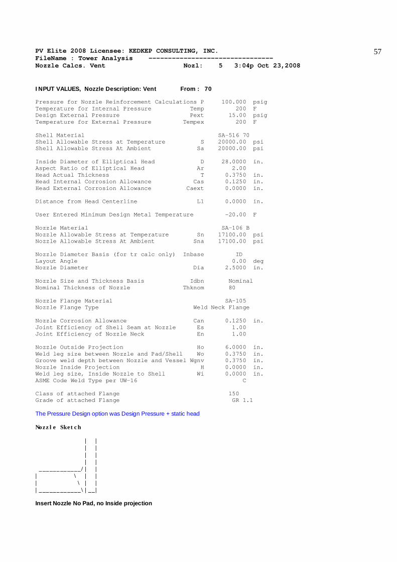
PV Elite 2008 Licensee: KEDKEP CONSULTING, INC. FileName : Tower Analysis -------------------------------- Nozzle Calcs. Vent Nozl: 5 3:04p Oct 23,2008
57
INPUT VALUES, Nozzle Description: Vent From : 70 Pressure for Nozzle Reinforcement Calculations P 100.000 psig Temperature for Internal Pressure Temp 200 F Design External Pressure Pext 15.00 psig Temperature for External Pressure Tempex 200 F Shell Material SA-516 70 Shell Allowable Stress at Temperature S 20000.00 psi Shell Allowable Stress At Ambient Sa 20000.00 psi Inside Diameter of Elliptical Head D 28.0000 in. Aspect Ratio of Elliptical Head Ar 2.00 Head Actual Thickness T 0.3750 in. Head Internal Corrosion Allowance Cas 0.1250 in. Head External Corrosion Allowance Caext 0.0000 in. Distance from Head Centerline L1 0.0000 in. User Entered Minimum Design Metal Temperature -20.00 F Nozzle Material SA-106 B Nozzle Allowable Stress at Temperature Sn 17100.00 psi Nozzle Allowable Stress At Ambient Sna 17100.00 psi Nozzle Diameter Basis (for tr calc only) Inbase ID Layout Angle 0.00 deg Nozzle Diameter Dia 2.5000 in. Nozzle Size and Thickness Basis Idbn Nominal Nominal Thickness of Nozzle Thknom 80 Nozzle Flange Material SA-105 Nozzle Flange Type Weld Neck Flange Nozzle Corrosion Allowance Can 0.1250 in. Joint Efficiency of Shell Seam at Nozzle Es 1.00 Joint Efficiency of Nozzle Neck En 1.00 Nozzle Outside Projection Ho 6.0000 in. Weld leg size between Nozzle and Pad/Shell Wo 0.3750 in. Groove weld depth between Nozzle and Vessel Wgnv 0.3750 in. Nozzle Inside Projection H 0.0000 in. Weld leg size, Inside Nozzle to Shell Wi 0.0000 in. ASME Code Weld Type per UW-16 C Class of attached Flange 150 Grade of attached Flange GR 1.1 The Pressure Design option was Design Pressure + static head Nozzle Sketch | | | | | | | | ____________/| | | \ | | | \ | | |____________\|__| Insert Nozzle No Pad, no Inside projection

PV Elite 2008 Licensee: KEDKEP CONSULTING, INC. FileName : Tower Analysis -------------------------------- Nozzle Calcs. Vent Nozl: 5 3:04p Oct 23,2008
58
NOZZLE CALCULATION, Description: Vent ASME Code, Section VIII, Division 1, 2007, UG-37 to UG-45 Actual Nozzle Inside Diameter Used in Calculation 2.323 in. Actual Nozzle Thickness Used in Calculation 0.276 in. Nozzle input data check completed without errors. Reqd thk per UG-37(a)of Elliptical Head, Tr [Int. Press] = (P*K1*D))/(2*S*E-0.2*P) per UG-37(a)(3) = (100.00*0.90*28.2500)/(2 *20000.00*1.00-0.2*100.00) = 0.0636 in. Reqd thk per UG-37(a)of Nozzle Wall, Trn [Int. Press] = (P*R)/(S*E-0.6*P) per UG-27 (c)(1) = (100.00*1.29)/(17100*1.00-0.6*100.00) = 0.0075 in. Required Nozzle thickness under External Pressure per UG-28 : 0.0124 in. UG-40, Thickness and Diameter Limit Results : [Int. Press] Effective material diameter limit, Dl 5.1460 in. Effective material thickness limit, no pad Tlnp 0.3775 in. Note: Taking a UG-36(c)(3)(a) exemption for Vent . This calculation is valid for nozzles that meet all the requirements of paragraph UG-36. Please check the Code carefully, especially for nozzles that are not isolated or do not meet Code spacing requirements. It may be necessary to force the program to print the areas per UG-37. UG-45 Minimum Nozzle Neck Thickness Requirement: [Int. Press.] Wall Thickness per UG45(a), tra = 0.1374 in. Wall Thickness per UG16(b), tr16b = 0.2188 in. Wall Thickness per UG45(b)(1), trb1 = 0.1957 in. Wall Thickness per UG45(b)(2), trb2 = 0.1356 in. Wall Thickness per UG45(b)(3), trb3 = Max(trb1, trb2, tr16b) = 0.2188 in. Std. Wall Pipe per UG45(b)(4), trb4 = 0.3026 in. Wall Thickness per UG45(b), trb = Min(trb3, trb4) = 0.2188 in. Final Required Thickness, tr45 = Max(tra, trb) = 0.2188 in. Available Nozzle Neck Thickness = .875 * 0.2760 = 0.2415 in. --> OK Minimum Design Metal Temperature (Nozzle Neck), Curve: B Minimum Temp. w/o impact per UCS-66 -20 F Minimum Temp. at required thickness -155 F Nozzle MDMT Thickness Calc. per UCS-66 (a)1(b), MIN(tn,t,te), Curve: B Minimum Temp. w/o impact per UCS-66 -20 F Minimum Temp. at required thickness -155 F Minimum Temp. w/o impact per UG-20(f) -20 F ANSI Flange MDMT including temperature reduction per UCS-66.1: Unadjusted MDMT of ANSI B16.5/47 flanges per UCS-66(c) -20 F Flange MDMT with Temperature reduction per UCS-66(b)(1)(b) -55 F Where the Temperature Reduction per UCS-66(b)(1)(b) is: Stress ratio, P / Ambient Rating = 100.00 / 285.00 = 0.351 Weld Size Calculations, Description: Vent Intermediate Calc. for nozzle/shell Welds Tmin 0.1510 in. Results Per UW-16.1:

PV Elite 2008 Licensee: KEDKEP CONSULTING, INC. FileName : Tower Analysis -------------------------------- Nozzle Calcs. Vent Nozl: 5 3:04p Oct 23,2008
59
Required Thickness Actual Thickness Nozzle Weld 0.1057 = 0.7 * TMIN 0.2651 = 0.7 * Wo in. The Drop for this Nozzle is : 0.0406 in. The Cut Length for this Nozzle is, Drop + Ho + H + T : 6.4156 in. PV Elite 2008 c1993-2008 by COADE Engineering Software
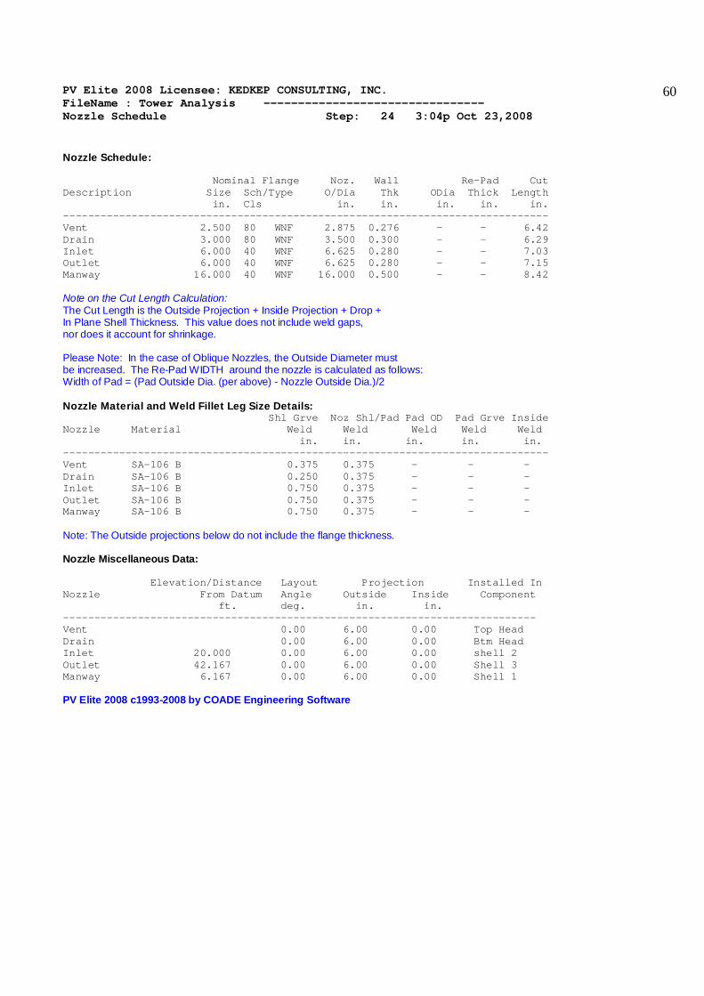
PV Elite 2008 Licensee: KEDKEP CONSULTING, INC. FileName : Tower Analysis -------------------------------- Nozzle Schedule Step: 24 3:04p Oct 23,2008
60
Nozzle Schedule: Nominal Flange Noz. Wall Re-Pad Cut Description Size Sch/Type O/Dia Thk ODia Thick Length in. Cls in. in. in. in. in. ------------------------------------------------------------------------------ Vent 2.500 80 WNF 2.875 0.276 - - 6.42 Drain 3.000 80 WNF 3.500 0.300 - - 6.29 Inlet 6.000 40 WNF 6.625 0.280 - - 7.03 Outlet 6.000 40 WNF 6.625 0.280 - - 7.15 Manway 16.000 40 WNF 16.000 0.500 - - 8.42 Note on the Cut Length Calculation: The Cut Length is the Outside Projection + Inside Projection + Drop + In Plane Shell Thickness. This value does not include weld gaps, nor does it account for shrinkage. Please Note: In the case of Oblique Nozzles, the Outside Diameter must be increased. The Re-Pad WIDTH around the nozzle is calculated as follows: Width of Pad = (Pad Outside Dia. (per above) - Nozzle Outside Dia.)/2 Nozzle Material and Weld Fillet Leg Size Details: Shl Grve Noz Shl/Pad Pad OD Pad Grve Inside Nozzle Material Weld Weld Weld Weld Weld in. in. in. in. in. ------------------------------------------------------------------------------ Vent SA-106 B 0.375 0.375 - - - Drain SA-106 B 0.250 0.375 - - - Inlet SA-106 B 0.750 0.375 - - - Outlet SA-106 B 0.750 0.375 - - - Manway SA-106 B 0.750 0.375 - - - Note: The Outside projections below do not include the flange thickness. Nozzle Miscellaneous Data: Elevation/Distance Layout Projection Installed In Nozzle From Datum Angle Outside Inside Component ft. deg. in. in. ---------------------------------------------------------------------------- Vent 0.00 6.00 0.00 Top Head Drain 0.00 6.00 0.00 Btm Head Inlet 20.000 0.00 6.00 0.00 shell 2 Outlet 42.167 0.00 6.00 0.00 Shell 3 Manway 6.167 0.00 6.00 0.00 Shell 1 PV Elite 2008 c1993-2008 by COADE Engineering Software

PV Elite 2008 Licensee: KEDKEP CONSULTING, INC. FileName : Tower Analysis -------------------------------- Nozzle Summary Step: 25 3:04p Oct 23,2008
61
Nozzle Calculation Summary Description Internal Ext MAPNC UG45 [tr] Weld Areas psig psig Path --------------------------------------------------------------------------- Drain 136.55 ... ... OK 0.226 OK Passed Manway 307.69 OK ... OK 0.226 OK Passed Inlet 118.83 OK ... OK 0.226 OK Passed Outlet 169.05 OK ... OK 0.219 OK Passed Vent 164.82 ... ... OK 0.219 OK Passed --------------------------------------------------------------------------- Min. - Nozzles 118.83 Inlet Min. Shell&Flgs 105.52 20 30 212.23 Computed Vessel M.A.W.P. 105.52 psig Note: MAWPs (Internal Case) shown above are at the High Point. Check the Spatial Relationship between the Nozzles From Node Nozzle Description Y Coordinate, Layout Angle, Dia. Limit 20 Drain 0.000 0.000 6.300 30 Manway 38.000 0.000 30.500 40 Inlet 204.000 0.000 12.630 60 Outlet 470.000 0.000 12.630 70 Vent 0.000 0.000 5.146 The nozzle spacing is computed by the following: = Sqrt( ll2 + lc2 ) where ll - Arc length along the inside vessel surface in the long. direction. lc - Arc length along the inside vessel surface in the circ. direction If any interferences/violations are found, they will be noted below. No interference violations have been detected ! PV Elite 2008 c1993-2008 by COADE Engineering Software

PV Elite 2008 Licensee: KEDKEP CONSULTING, INC. FileName : Tower Analysis -------------------------------- Vessel Design Summary Step: 26 3:04p Oct 23,2008
62
Design Code: ASME Code Section VIII Division 1, 2007 Diameter Spec : 40.000 x 28.000 in. ID Vessel Design Length, Tangent to Tangent 41.33 ft. Distance of Bottom Tangent above Grade 3.00 ft. Distance of Base above Grade 0.00 ft. Specified Datum Line Distance 0.00 ft. Skirt Material SA-516 70 Shell/Head Matl SA-516 70 Stiff Ring Matl SA-516 70 Nozzle Material SA-106 B Internal Design Temperature 200 F Internal Design Pressure 100.00 psig External Design Temperature 200 F External Design Pressure 15.00 psig Maximum Allowable Working Pressure 105.52 psig External Max. Allowable Working Pressure 21.32 psig Hydrostatic Test Pressure 130.00 psig Required Minimum Design Metal Temperature -20 F Warmest Computed Minimum Design Metal Temperature -39 F Wind Design Code NBC-2005 Earthquake Design Code NBC 2005 Element Pressures and MAWP: psig Element Desc Internal External M.A.W.P Corr. All. Btm Head 100.000 15.000 105.525 0.1250 Shell 1 100.000 15.000 518.293 0.1250 shell 2 100.000 15.000 518.293 0.1250 Cone 100.000 15.000 502.998 0.1250 Shell 3 100.000 15.000 732.759 0.1250 Top Head 100.000 15.000 300.353 0.1250 Stiffener Ring Specifications: Elevation ft. Selected Type User Description 31.97 Bar 1.75 x 1.00 Ring:[1 of 1] Element "To" Elev Length Element Thk R e q d T h k Joint Eff Type ft. ft. in. Int. Ext. Long Circ Skirt 3.00 3.000 0.500 No Calc ------- 0.70 0.70 Ellipse 3.17 0.167 0.250 0.243 ------- 0.85 0.70 Cylinder 17.67 14.500 0.750 0.244 ------- 0.85 0.70 Cylinder 32.17 14.500 0.750 0.244 ------- 0.85 0.70 Conical 34.17 2.000 0.750 0.247 ------- 0.85 0.70 Cylinder 44.17 10.000 0.750 0.219 ------- 0.85 0.70 Ellipse 44.33 0.167 0.375 0.219 ------- 0.85 0.70 Element thicknesses are shown as Nominal if specified, otherwise are Minimum External Pressure Calculations | | External | External | External | External | From| To | Actual T. | Required T.|Des. Press. | M.A.W.P. | | | in. | in. | psig | psig | 10| 20| 0.00000 | No Calc | 0.00000 | No Calc | 20| 30| 0.25000 | 0.22986 | 15.0000 | 21.3159 | 30| 40| 0.75000 | 0.44010 | 15.0000 | 83.2720 | 40|Ring| 0.75000 | 0.44010 | 15.0000 | 83.2720 |

PV Elite 2008 Licensee: KEDKEP CONSULTING, INC. FileName : Tower Analysis -------------------------------- Vessel Design Summary Step: 26 3:04p Oct 23,2008
63
Ring| 50| 0.75000 | 0.16469 | 15.0000 | 357.430 | 50| 60| 0.75000 | 0.22772 | 15.0000 | 338.280 | 60| 70| 0.75000 | 0.29430 | 15.0000 | 345.111 | 70| 80| 0.37500 | 0.19944 | 15.0000 | 127.364 | External Pressure Calculations | | Actual Len.| Allow. Len.| Ring Inertia | Ring Inertia | From| To | Bet. Stiff.| Bet. Stiff.| Required | Available | | | ft. | ft. | in**4 | in**4 | 10| 20| No Calc | No Calc | No Calc | No Calc | 20| 30| No Calc | No Calc | No Calc | No Calc | 30| 40| 29.2444 | 442.4E+21 | No Calc | No Calc | 40|Ring| 29.2444 | 442.4E+21 | No Calc | No Calc | Ring| 50| 0.20000 | 8.656E+21 | 0.89879 | 2.20599 | 50| 60| 1.71084 | 1.71084 | No Calc | No Calc | 60| 70| 10.3611 | 19.68E+27 | No Calc | No Calc | 70| 80| No Calc | No Calc | No Calc | No Calc | Wind/Earthquake Shear, Bending | | Distance to| Cummulative|Earthquake | Wind | Earthquake | From| To | Support| Wind Shear| Shear | Bending | Bending | | | ft. | lb. | lb. | ft.lb. | ft.lb. | 10| 20| 1.50000 | 2638.74 | 566.975 | 55501.9 | 15647.8 | 20| 30| 3.08333 | 2443.48 | 563.323 | 47878.6 | 13952.4 | 30| 40| 10.4167 | 2433.15 | 562.296 | 47472.2 | 13858.6 | 40| 50| 24.9167 | 1511.60 | 462.421 | 18872.8 | 6429.37 | 50| 60| 33.1667 | 590.055 | 227.257 | 3635.76 | 1429.20 | 60| 70| 39.1667 | 481.323 | 190.032 | 2564.38 | 1011.91 | 70| 80| 44.2500 | 29.5479 | 11.5663 | 10.0218 | 3.92298 | Abs Max of the all of the Stress Ratio's : 0.6367 Basering Data : Basering W/Gussets & Chair Cap Thickness of Basering 1.5000 in. Inside Diameter of Basering 41.5000 in. Outside Diameter of Basering 51.5000 in. Nominal Diameter of Bolts 2.0000 in. Diameter of Bolt Circle 47.5000 in. Number of Bolts 8 Thickness of Gusset Plates 0.7500 in. Average Width of Gusset Plates 4.5000 in. Height of Gussets 9.0000 in. Distance between Gussets 3.5000 in. Thickness of Top Plate or Ring 1.7500 in. Circumferential Width of the Top Plate 7.0000 in. Radial Width of the Top Plate 4.5000 in. Wind Moment on Support 55502. ft.lb. Wind Shear on Support 2639. lb. Earthquake Moment on Support 15648. ft.lb. Earthquake Shear on Support 567. lb. Note: Wind and Earthquake moments include the effects of user defined forces and moments if any exist in the job and were specified to act (compute loads and stresses) during these cases. Also included are moment effects due to eccentric weights if any are present in the input. Weights:

PV Elite 2008 Licensee: KEDKEP CONSULTING, INC. FileName : Tower Analysis -------------------------------- Vessel Design Summary Step: 26 3:04p Oct 23,2008
64
Fabricated - Bare W/O Removable Internals 17009.3 lbm Shop Test - Fabricated + Water ( Full ) 36805.8 lbm Shipping - Fab. + Rem. Intls.+ Shipping App. 17009.3 lbm Erected - Fab. + Rem. Intls.+ Insul. (etc) 17009.3 lbm Empty - Fab. + Intls. + Details + Wghts. 17009.3 lbm Operating - Empty + Operating Liquid (No CA) 17009.3 lbm Field Test - Empty Weight + Water (Full) 36805.8 lbm PV Elite 2008 c1993-2008 by COADE Engineering Software