table of contents miscellaneous common conversions.....91 bridge design manual – may 2018 oregon...
TRANSCRIPT

Bridge Design Manual – May 2018 Oregon Department of Transportation
Section 3 – Processes & Layout
3-1
Table of Contents 3.1 Section 3 – Introduction ............................................................................................................ 4
3.1.1 Procedure and Process Guides .............................................................................................. 4
3.2 Bridge Design Software ............................................................................................................. 5 3.2.1 Design Software ...................................................................................................................... 5 3.2.2 Software Verification ............................................................................................................... 6 3.2.3 MathCAD Template Library ..................................................................................................... 6
3.3 Bridge Design Process (Design-Bid-Build), Overview ............................................................ 7 3.3.1 Scoping .................................................................................................................................... 7 3.3.2 Project Initiation (Kick-Off) ....................................................................................................... 8 3.3.3 50% TS&L (Proof of Concept Plans) ....................................................................................... 8 3.3.4 TS&L Report ............................................................................................................................ 8 3.3.5 Design Acceptance Plans Package ........................................................................................ 9 3.3.6 Preliminary Plans Package Milestone ..................................................................................... 9 3.3.7 Advance Plans Package Milestone ....................................................................................... 10 3.3.8 Final Plans Package Milestone ............................................................................................. 11 3.3.9 PS&E Milestone..................................................................................................................... 11 3.3.10 Bridge Design Project Close Out ...................................................................................... 11
3.4 Roles & Responsibilities .......................................................................................................... 12 3.4.1 Key Personnel ....................................................................................................................... 12 3.4.2 Large or Multiple Bridge Projects .......................................................................................... 15
3.5 Quality ...................................................................................................................................... 16 3.5.1 Introduction ............................................................................................................................ 16 3.5.2 Definitions .............................................................................................................................. 17 3.5.3 Design Quality Plans ............................................................................................................. 18 3.5.4 Bridge Design Quality Documentation .................................................................................. 19 3.5.5 Bridge Design Quality ‘Touchpoints’ ..................................................................................... 20 3.5.6 Design Reviews ..................................................................................................................... 20 3.5.7 Design Checks ...................................................................................................................... 21 3.5.8 Qualifications of Bridge Designer, Checker & Reviewer ....................................................... 23 3.5.9 Performance Measures ......................................................................................................... 23 3.5.10 Troubleshooting Bridge Design Quality ............................................................................ 23 3.5.11 Recovery Plans ................................................................................................................. 24 3.5.12 Quality Audits .................................................................................................................... 24 3.5.13 Work Assignments ............................................................................................................ 24 3.5.14 Training & Mentoring ......................................................................................................... 24
3.6 (Reserved) ................................................................................................................................. 26
3.7 QPL / research ......................................................................................................................... 26 3.7.1 Qualified Products List (QPL) ................................................................................................ 26 3.7.2 Research ............................................................................................................................... 26
3.8 (Reserved) ................................................................................................................................. 27
3.9 Preliminary Design / DAP / TS&L ......................................................................................... 27 3.9.1 Introduction ............................................................................................................................ 27 3.9.2 Purpose of TS&L ................................................................................................................... 28 3.9.4 TS&L Approval ...................................................................................................................... 30 3.9.5 Multiple Bridge Projects ......................................................................................................... 30 3.9.6 TS&L Report .......................................................................................................................... 30 3.9.7 Alternatives Study ................................................................................................................. 30

Bridge Design Manual – May 2018 Oregon Department of Transportation
Section 3 – Processes & Layout
3-2
3.9.8 Bridge Design Criteria & Standards Assessment .................................................................. 31 3.9.9 Design Deviations and Exceptions ........................................................................................ 31 3.9.10 TS&L Report with Memo ................................................................................................... 31 3.9.11 TS&L Report with Narrative .............................................................................................. 31 3.9.12 Engineer’s Estimate @ TS&L ........................................................................................... 32 3.9.13 TS&L Plan Sheet(s) .......................................................................................................... 32 3.9.14 TS&L Templates ............................................................................................................... 33
3.10 Final Design / PS&E ................................................................................................................ 34 3.10.1 Introduction ....................................................................................................................... 34 3.10.2 Sealing & Signing Requirements ...................................................................................... 34 3.10.3 Contract Plans ................................................................................................................... 35 3.10.4 Specifications & Special Provisions .................................................................................. 35 3.10.5 Engineer’s Estimate .......................................................................................................... 35 3.10.6 Engineer’s Estimate of Probable Construction Schedule ................................................. 36 3.10.7 Calculations & Calculation Books ..................................................................................... 36 3.10.8 Bridge Load Rating ........................................................................................................... 40 3.10.9 Operations and Maintenance Manuals ............................................................................. 40
3.11 PS&E to Award ....................................................................................................................... 42 3.11.1 Introduction ....................................................................................................................... 42 3.11.2 Changes to Bridge Deliverables after PS&E .................................................................... 42 3.11.3 Bridge Design Project Close-Out ...................................................................................... 42 3.11.4 Request for Information (RFI) ........................................................................................... 42 3.11.5 Addenda Letters ................................................................................................................ 43
3.12 Construction Support .............................................................................................................. 44 3.12.1 Introduction ....................................................................................................................... 44 3.12.2 Communications during Construction ............................................................................... 44 3.12.3 Shop Drawing Review ....................................................................................................... 44 3.12.4 Temporary Works Review ................................................................................................. 44 3.12.5 Construction Support Close-Out ....................................................................................... 44
3.13 (Reserved) ................................................................................................................................. 45
3.14 Coordination with other Project Team Members ................................................................ 46 3.14.1 General ............................................................................................................................. 46 3.14.2 Project Management ......................................................................................................... 46 3.14.3 Survey and Mapping, & Right Of Way .............................................................................. 47 3.14.4 Roadway ........................................................................................................................... 48 3.14.5 Traffic and Mobility ............................................................................................................ 55 3.14.6 Foundations and Geotechnical ......................................................................................... 56 3.14.7 Hydraulics and Scour ........................................................................................................ 57 3.14.8 Environmental ................................................................................................................... 61 3.14.9 Storm Water ...................................................................................................................... 64 3.14.10 Utilities ............................................................................................................................... 65 3.14.11 Railroad ............................................................................................................................. 71 3.14.12 Public Involvement ............................................................................................................ 72
Appendix – Section 3.4 – Roles & Responsibilities ................................................................. 73 A3.4.1 Bridge Designer ................................................................................................................ 73 A3.4.2 Bridge Reviewer ................................................................................................................ 76 A3.4.3 Bridge Design Checker ..................................................................................................... 79 A3.4.4 Bridge Subject Matter Expert ............................................................................................ 80 A3.4.5 Bridge Design Coordinator ................................................................................................ 81 A3.4.6 Bridge Quality Auditor ....................................................................................................... 82
Appendix – Section 3.5 – Quality ............................................................................................ 83

Bridge Design Manual – May 2018 Oregon Department of Transportation
Section 3 – Processes & Layout
3-3
Bridge EDMS QC Checklist ................................................................................................................ 83
Bridge Drafter QC Checklist for TS&L Plan Sheet(s) ...................................................................... 83
Bridge Drafter QC Checklist for Advance Plans (95%) Plan Sheets .............................................. 83
Appendix – Section 3.91 – Metric Conversion ........................................................................ 84 A3.91.1 Introduction ....................................................................................................................... 84 A3.91.2 Basic Units ........................................................................................................................ 85 A3.91.3 Derived Units ..................................................................................................................... 85 A3.91.4 Metric Conversion Factors ................................................................................................ 87 A3.91.5 Metric Procedural Rules .................................................................................................... 88 A3.91.6 Bridge Plan and Preparation Guidelines ........................................................................... 88 A3.91.7 Miscellaneous Common Conversions............................................................................... 91

Bridge Design Manual – May 2018 Oregon Department of Transportation
Section 3 – Processes & Layout
3-4
Note: Revisions for May, 2018 are marked with yellow highlight. Deleted text is not marked; past editions of the BDM are available for comparison. 3.1 SECTION 3 – INTRODUCTION BDM Section 3 contains standards and practices pertinent to design procedures and quality processes for completing highway bridge and structure design. See BDM 1 for standards and practices pertinent to design of highway bridges and structures. See BDM 2 for design guidance pertinent to highway bridges and structures design. 3.1.1 Procedure and Process Guides ODOT Project Delivery Guidebook ODOT Practical Design Strategy and Guide

Bridge Design Manual – May 2018 Oregon Department of Transportation
Section 3 – Processes & Layout
3-5
3.2 BRIDGE DESIGN SOFTWARE 3.2.1 Design Software 3.2.2 Software Verification 3.2.3 MathCAD Template Library 3.2.1 Design Software (1) Supported Software The following programs are used and supported by the Bridge Section: SOFTWARE NAME SYSTEM* USE FOR QUESTIONS, CONTACT Midas Civil 7-64 bridge analysis and design DFSAP 7-64 LPile 7-64 Group 7-64 ODOT-Col 7-32 column analysis PAP 7-64 FHWA INSTRUCT Terminal
Services
Brass Girder LRFD 7-64 Brass Girder STD 7-64 Brass Library Utility 7-64 Brass Pole PGSuper 7-64 WSDOT precast design program PSBeam 7-64 Response 2000 7-64 Reinforced concrete sectional analysis
using Modified Compression Field theory
SIMON 7-64 STLBridge LRFD 7-64 steel bridge design using LRFD QConBridge 7-64 WSDOT live load analysis program for
continuous frames
RspBr2 7-32 Convert 4.1 7-64 Mathcad 15 7-64 Mathcad Prime 7-64 * Example: 7-64 indicates the software will run using Windows 7 – 64 bit.

Bridge Design Manual – May 2018 Oregon Department of Transportation
Section 3 – Processes & Layout
3-6
(2) Unsupported Software With the computer upgrade from Windows XP to Windows 7, most of the bridge legacy programs are out-dated. The following programs are incompatible with the 64-bit systems or will no longer be supported:
• Brig2d (replaced by RspBr2) • CrkCol • CrvBrgPc (Midas and GTStrudl have this function) • DkElev (Microstation can perform this function) • LdSort • MStrudl (no longer in business) – Midas and GTStrudl have this function • ODOT’s pole program (uses MStrudl) • Oregon’s PSBeam (not Erikssons PsBeam, which ODOT now uses) • Ultcol (Xtract can support this function) • UltFtg (program needed to do simple analysis for footing design (on piling and shallow
foundation). • WinStrudl (no longer in business) • XSection and WFrame – Caltrans programs • Drain2dx – dynamic response analysis of inelastic plane structures • GTStrudl – finite element analysis • LUSAS • SAP 2000 – finite element analysis • SimQuake – DOS – simulation of time, position, and magnitude of earthquakes • Xtract – CalTrans – substitute for XSection and WFrame
3.2.2 Software Verification [Reserved for future use] 3.2.3 MathCAD Template Library The following MathCAD Standard Bridge Rail Calculations are posted on the Bridge Standards website under the “Software Tools for Design” section. The calculations document the bridge rail design and capacity:
• BR200_Calcs_2016 for BR200 • BR206_Calcs_2016 for BR206 • BR208_Calcs_2016 for BR208 • BR214_Calcs_2014 for BR214 (will be updated in the near future) • BR221_Calcs_2016 for BR221 • BR290_Calcs_2016 for BR290 • (will be updated in the near future)
The spreadsheet “Summary of ODOT Standard Rail Capacities” summarizes all the bridge rail capacities for deck overhang design. Also available on the Bridge Intranet are the following Calculation Templates available for ODOT designers use to promote standardization and efficiency.
• Deck Overhang with Concrete Bridge Rail (MathCAD and MathCAD Prime)

Bridge Design Manual – May 2018 Oregon Department of Transportation
Section 3 – Processes & Layout
3-7
3.3 BRIDGE DESIGN PROCESS (DESIGN-BID-BUILD), OVERVIEW 3.3.1 Scoping 3.3.2 Project Initiation (Kick-Off) 3.3.3 50% TS&L (Proof of Concept Plans) 3.3.4 TS&L Report 3.3.5 Design Acceptance Plans Package 3.3.6 Preliminary Plans Package Milestone 3.3.7 Advance Plans Package Milestone 3.3.8 Final Plans Package Milestone 3.3.9 PS&E Milestone 3.3.10 Bridge Design Project Close-Out 3.3.1 Scoping The Project (by others) – Scoping involves a reconnaissance level look at one or more alternatives for a project. It involves more planning, conceptual design, and description than the project-level design performed after STIP programming. This level of planning assists in securing funding and determining ‘Level of Effort’ required by various work units. Site constraints are identified; assumed or known design exceptions or deviations are noted; and anticipated outsourcing of work is noted. Bridge Design – Potential Bridge Program projects are initiated by the Bridge Program Unit from queries run on the State’s Bridge Data. A ‘Desk Scope’ is completed, and an ODOT Project Business Case is drafted by the Bridge Program Manager. This information is then sent to the Region for ‘Field Scoping’. After the Region Scoping Team has performed the ‘Field Scope’, it is sent back to the Bridge Program Unit for review and reconciliation, and the Bridge program Manager updates the ODOT Project Business Case. The final ODOT Project Business Case is provided to a Project Leader by a Region Area Manager after STIP programming, and eventually Project Initiation. Also see Highway Division Directive DES 01.

Bridge Design Manual – May 2018 Oregon Department of Transportation
Section 3 – Processes & Layout
3-8
3.3.2 Project Initiation (Kick-Off) The Project (by others) – Project Initiation is when the project is ‘kicked off’ by the Project Leader. Final refinements to the scope, schedule and budget occur at the Project Kick-Off meeting. Bridge Design – The Bridge Reviewer meets with the Bridge Designer a couple weeks prior to the Project’s Kick-Off meeting to prepare by reviewing the Bridge Design Work Order (for outsourced work also see the statement of work of A&E contract), schedule and budget, project charters, the project’s scope and the ODOT Project Business Case (if available). The Bridge portion of the Region Quality Control Plan is also reviewed at this time, and supplemented to cover any project specific needs. Also see PDLT Operational Notice PD-02. Verify the proposed bridge/structures scope of the project design as well as begin development of design deviations and exceptions. Bridge designers use available scoping information and draft project charters to prepare the Bridge Design Criteria and Standards Assessment. Confirm completion of load rating, deck testing and certain preliminary analyses of existing bridges that will be not be replaced. Ensure results are appropriately reflected in the draft project charter and other work description documents. The Bridge Designer and Reviewer complete the appropriate Bridge QC Checklist found in BDM A3.5. A list of responsibilities at this milestone for the Bridge Reviewer and Designer can be found in BDM A3.4. 3.3.3 50% TS&L (Proof of Concept Plans) The Project (by others) – Concept Plans consists of enough detail to “proof” the project concept that has been put forth. Site constraints are identified, and alignments are close to final. Consider permanent and temporary traffic control, and note specialty specification items. Include as many bid items as can be identified in cost estimates. Other work completed by others at this stage include: survey control established, survey topography gathered, survey base map produced, existing right of way determined, environmental base map produced, Area of Potential Impact (API) identified, draft utility conflicts identified, horizontal and vertical alignments calculated, bridge bent locations set, retaining wall locations set. Bridge Design – The Alternatives Study and a rough draft of the TS&L Narrative (or Memo) are complete and ready to review by the Bridge Reviewer. Review and update the Bridge Design Criteria and the Bridge Design Standards Assessment and create a list of design deviations and exceptions for each alternative. Structural analysis calculations may need to be started and sufficiently advanced so can meet Preliminary Plans milestone needs. Include “significant cost” bid items on the Engineer’s Estimate @ TS&L. A draft TS&L Plan Sheet may be prepared to include with the other project Concept Plans. Coordinate need with the Project Team. The Bridge Designer and Reviewer complete the appropriate Bridge QC Checklist found in BDM A3.5. A list of responsibilities at this milestone for the Bridge Reviewer and Designer can be found in BDM A3.4. 3.3.4 TS&L Report The Project (by others) – Is nearing the Design Acceptance Plans (DAP) milestone. Bridge Design – The TS&L Report (consisting of the Alternatives Study, TS&L Memo or Narrative, TS&L Plan Sheets, Engineer’s Estimate, Standards Assessment, and Design Deviations/Exceptions) is complete, has been reviewed and approved by the Bridge Reviewer, and is ready to publish in the DAP. Submit TS&L Report to the Project Leader.

Bridge Design Manual – May 2018 Oregon Department of Transportation
Section 3 – Processes & Layout
3-9
Provide bridge deliverables to the appropriate personnel to complete a Construction Review, Maintenance Review and Regional Bridge Lead Engineer Review (see BDM 3.5.6.4). Schedule a review meeting with Construction and Maintenance personnel to discuss comments. The Bridge Designer, Reviewer and Drafter complete the appropriate Bridge QC Checklist found in BDM A3.5. A list of responsibilities at this milestone for the Bridge Reviewer and Designer can be found in BDM A3.4. 3.3.5 Design Acceptance Plans Package The Project (by others) – Design Acceptance Plans (DAP) provide sufficient detail of project elements and staging to identify right of way and utility impacts, utility relocation needs, and to allow application for permits. Complete staging except for minor details. At this milestone, alignments are final and the project ‘footprint’ is set. Changes after this stage should be seldom needed, and work after this stage is adding detail and refining the design. Each project team member is to review others’ DAP deliverables to ensure the work is compatible between disciplines, and there are no discrepancies. Roadway often takes the lead on common products, such as distributing the DAP and compiling a complete cost estimate. A Design Narrative may be prepared that incorporates all sections’ commentaries. Reference may be made to other complete documents, such as the Bridge TS&L Report, providing only minimal data in the Design Narrative for such sections. Some items to be completed by others at or near the DAP milestone include:
• Roadway: Approved Design Exceptions, Project Narrative, DAP Cost Estimate • Geotechnical: Preliminary Geotechnical recommendations documented • Hydraulics: Hydraulic recommendations and plans
Bridge Design – Respond to any needs identified by the Project Leader. Attend the Design Acceptance Workshop (DAW), if scheduled. Some items to be completed at or near the DAP milestone include:
• Bridge: TS&L Report (including Alternative Study), Approved Design Deviations and Exceptions, Information for permits
• Start structural analysis calculations and Preliminary contract plans. • Write specialty specs with enough detail to give reviewers an idea of the work and pay items
involved. Include most of the bid items in cost estimates, although quantities will not be accurately calculated at this time.
A list of responsibilities at this milestone for the Bridge Reviewer and Designer can be found in BDM A3.4. 3.3.6 Preliminary Plans Package Milestone The Project (by others) – Preliminary Plans incorporate adjustments that are needed due to further refinement with right of way, utility, and permitting negotiations that have occurred. Decisions affecting the footprint of the project are made by this time. Each project team member is to review others’ Preliminary Plans deliverables to ensure the work is compatible between disciplines, and there are no discrepancies. Some items to be completed by others at the Preliminary Plans milestone include:
• Roadway: Preliminary Plans, Bid Summary/Cost Estimate • Geotechnical: Draft Geotechnical Report

Bridge Design Manual – May 2018 Oregon Department of Transportation
Section 3 – Processes & Layout
3-10
• Hydraulics: Draft Hydraulics Report, Storm Water Management Plan • Environmental: Obtaining permits is continuing during this phase • Utilities: Work with utility companies to establish utility relocations
Bridge Design – Substantially complete structural calculations and prepare Preliminary contract plans. All plan sheets are started and prepared to approximately 70% complete, showing the basic geometry of all major elements. Identify boilerplate special provisions using SPLIST. When there is no boilerplate special provision, provide a draft special provision. Complete the Engineer’s Estimate @ Preliminary Plans including all bid items with rough calculated quantities. Provide bridge deliverables to the Project Leader for inclusion in the Preliminary Plans review package. Provide bridge deliverables to the appropriate personnel to complete a Construction Review, Maintenance Review and State Bridge Engineer Review (see BDM 3.5.6.4). Schedule a review meeting with Construction and Maintenance personnel to discuss comments. Some items to be completed at the Preliminary Plans milestone include:
• Preliminary Plans, Engineer’s Estimate, List of anticipated special provisions • All plan sheets are started and included in the review package. • Engineer’s Estimate is to include all bid items with rough calculated quantities. • Include boilerplate special provisions (i.e., compilation of boilerplate special provisions straight
from the ODOT webpage; without “refining” work). The Bridge Designer and Reviewer complete the appropriate Bridge QC Checklist found in BDM A3.5. A list of responsibilities at this milestone for the Bridge Reviewer and Designer can be found in BDM A3.4. 3.3.7 Advance Plans Package Milestone The Project (by others) – Advance Plans include all items necessary to bid and build the project. Each project team member is to review others’ Advance Plans deliverables to ensure the work is compatible between disciplines; and review the entire plan set for clarity and consistency. Some items to be completed by others at the Advance Plans milestone include:
• Roadway: Advance Plans, Construction Cost Estimate, Special Provisions, • Construction: Construction Schedule • Geotechnical: Stamped Geotechnical Report • Hydraulics: Stamped Hydraulics Report, stamped Storm Water Management Plan • Environmental: Obtaining permits may be continuing during this phase
Bridge Design – Complete structural analysis calculations and prepare Advance contract plans. Prepare plan sheets to approximately 95% complete (only lacking corrections based on QC Checking comments), including all geometry and details necessary for bidding and construction. Complete draft special provisions, including specialty special provisions, and Engineer’s Estimate @ Advance Plans, including a complete itemized list of bid items and accurately calculated quantities. Complete the Engineer’s Estimate of Probable Construction Schedule when required by project team. Provide bridge deliverables to the Project Leader for inclusion in the Advance Plans review package; to the Bridge Checker for detailed structural QC check. Some items to be completed at the Advance Plans milestone include:
• Advance Plans, Engineer’s Estimate, Special Provisions The Bridge Designer, Reviewer, Checker and Drafter complete the appropriate Bridge QC Checklist found in BDM A3.5. A list of responsibilities at this milestone for the Bridge Reviewer, Designer, and Checker can be found in BDM A3.4.

Bridge Design Manual – May 2018 Oregon Department of Transportation
Section 3 – Processes & Layout
3-11
3.3.8 Final Plans Package Milestone The Project (by others) – Final Plans consist of digitally signing the plan sheets and preparing for submittal of the design work and finalizing the PS&E package. Some items complete at the Final Plans milestone include:
• Roadway: Final Plans, Construction Cost Estimate, Final Special Provisions • Construction: Final Construction Schedule • Environmental: Approved permits
Bridge Design – Address comments from the detailed structural QC check and other reviews. Finalize structural analysis calculations and prepare Final contract plans. Complete plan sheets (100%). Complete final special provisions, final Engineer’s Estimate of Probable Construction Schedule when required by project team, and Engineer’s Estimate @ Final Plans. Provide bridge deliverables to the Project Leader for inclusion in the Final Plans package. Also see PDLT Operational Notice PD-02 and Final PS&E Submittal Checklist, and ensure the Bridge-related aspects of these documents are complete. Some items to be completed at the Advance Plans milestone include:
• Final Plans, Engineer’s Estimate and Final Special Provisions The Bridge Designer, Reviewer and Checker complete the appropriate Bridge QC Checklist found in BDM A3.5. A list of responsibilities at this milestone for the Bridge Reviewer, Designer and Checker can be found in BDM A3.4. 3.3.9 PS&E Milestone The Project (by others) – At PS&E all the contract documents prepared by the Project Team are submitted to the Office of Project Letting by the Project Leader to begin the process of advertising and bid letting. Bridge Design – Complete the structural analysis Bridge Designer and Checker calculation book(s). Make a pdf of the calculation book(s) and submit to the Bridge Reviewer. Assist the Project Leader to address any PS&E Package deficiencies before advertising; and to address any RFIs and Addendum Letters during advertising. Prepare the “design” bridge load rating. The Bridge Designer, Reviewer and Checker complete the appropriate Bridge QC Checklist found in BDM A3.5. A list of responsibilities at this milestone for the Bridge Reviewer, Designer and Checker can be found in BDM A3.4. 3.3.10 Bridge Design Project Close Out Bridge Design – Within 60 days after Award, complete ‘Bridge Design Close-Out’ documents, per BDM 3.11.3.

Bridge Design Manual – May 2018 Oregon Department of Transportation
Section 3 – Processes & Layout
3-12
3.4 ROLES & RESPONSIBILITIES 3.4.1 Key Personnel 3.4.2 Large or Multiple Bridge Projects 3.4.1 Key Personnel The following is a list of ‘key’ roles and responsibilities related to the design of a bridge. This is not an exhaustive list of responsibilities and duties for the position noted. This list is intended to supplement the ODOT Project Delivery Guide (PDG), not supersede it. Also see PDLT Operational Notice PD-01. State Bridge Engineer
• The role of the State Bridge Engineer is to provide management and leadership to the State’s Bridge Engineering Section.
• The State Bridge Engineer is responsible for: o Overseeing the Bridge Program. o Overseeing the Bridge Operations and Standards Unit. o Overseeing the Bridge Preservation Design Unit. o Overseeing the Regional Bridge Design Unit.
Bridge Program Manager
• The role of the Bridge Program Manager is to provide management and leadership to the State’s Bridge Program Unit.
• The Bridge Program Manager is responsible for: o Developing and programing the Bridge Program STIP. o Approving final scope of work for Bridge Program projects. o Approving changes to and funding for Bridge Program projects.
Bridge Operations and Standards Manager
• The role of the Bridge Operations and Standards Manager is to provide management and leadership to the State’s Bridge Operations and Standards Unit.
• The Bridge Operations and Standards Manager is responsible for: o Providing Subject Matter Experts for Bridge Designers and Drafters to consult with during
the development of projects. o Maintaining the Bridge Design Quality Program, and providing Quality Auditors to audit
bridge designs. o Maintaining the Bridge Design Manual and Bridge CAD Manual. o Maintaining the Bridge Standard Drawings and Details. o Modifying existing or developing new standards for design. o Providing technical training to bridge designers and drafters.

Bridge Design Manual – May 2018 Oregon Department of Transportation
Section 3 – Processes & Layout
3-13
Bridge Design Manager • The role of the Bridge Design Manager is to provide management and leadership to the State’s
Regional Bridge Design Unit. • The Bridge Design Manager is responsible for:
o Satisfying the staffing needs of the various bridge and structural analysis needs by providing the appropriate resources.
o Developing and implementing strategies to ensure the sustainability of the bridge design technical discipline statewide.
Regional Bridge Lead Engineer
• The role of the Regional Bridge Lead Engineer is to represent the Bridge Design Manager in the regions.
• The Regional Bridge Lead Engineer is responsible for: o Performing lead engineer duties associated with the Regional Bridge Design Unit.
Bridge Reviewer
• The role of the Bridge Reviewer is to perform the QC/QA design review from prior to Project Initiation through Project Award.
• The Bridge Reviewer is responsible for: o Checking in with, and mentoring, the Bridge Designer and Checker at key points in time
to ensure work is progressing in a satisfactory manner to meet or beat schedule and budget.
o Reviewing work and deliverables prepared by the Bridge Designer and Checker. Bridge Designer
• The role of the Bridge Designer is to provide structural analysis and design for the Agency’s maintenance and other structural design related needs.
• The Bridge Designer is responsible for: o Performing structural analysis and design for bridges and other highway related structures.
Bridge Design Checker
• The role of the Bridge Design Checker is to perform the QC bridge design check of the structural analysis and design for bridges and other highway related structures.
• The Bridge Design Checker is responsible for: o Performing the QC bridge design check of the structural analysis and design for bridges
and other highway related structures. Bridge Design Project Lead
• The role of the Bridge Design Project Lead is to lead and coordinate the bridge design on projects with multiple bridge designers or bridges.
• The Bridge Design Project Lead is responsible for: o Coordinating design, estimating and specification writing among the bridge designers on
the bridge project design team. o Reviewing developing bridge designs to ensure consistency is maintained between
bridge designs. o Attending Project Team meetings and representing the bridge project design team.
ODOT Project Leader
• The role of the Project Leader is facilitating and coordinating project teams. • The Project Leader is responsible for:
o Scope, schedule and budget for projects developed using ODOT staff.

Bridge Design Manual – May 2018 Oregon Department of Transportation
Section 3 – Processes & Layout
3-14
A&E Project Manager • The role of the A&E Project Manager is facilitating and coordinating project teams. • The A&E Project Manager is responsible for:
o Scope, schedule, budget, and quality of contracted projects/work. Local Agency Liaisons
• The role of the Local Agency Liaison is to manage project development for local government projects.
• The Local Agency Liaison is responsible for: o Delivery of local government projects, including local bridge projects.
Region Tech Center Manager
• The role of the Region Tech Center Manager is to provide management and leadership to the Region Tech Center.
• The Region Tech Center Manager is responsible for: o Managing technical staff assigned to the Region involved in project development. o Developing and implementing a design quality control program within the Region Tech
Center. o Ensuring project work is consistent with the Region Quality Plan. o Monitoring quality assurance performance.
Consultant Project Manager (CPM)
• The role of the Consultant Project Manager is to serve as project leader in the delivering of entire projects using full-service consulting contracts.
• The Consultant Project Manager is responsible for: o Coordinating with consultants for delivery of full-service outsourced projects. o Scope, schedule and budget for projects developed using outsourced staff.
Project Managers
• The role of the Project Manager is to administer contracts for construction. • The Project Manager is responsible for:
o Construction management for in-house and outsourced projects. Area Manager
• The role of the Area Manager is to oversee the complete project lifecycle including: scoping, preliminary engineering, and construction phases of work.
• The Area Manager is responsible for: o The delivery of projects in their area.
A&E Bridge Design Consultant
• May be contracted to perform the design duties associated with the Bridge Project Lead, Senior Bridge Engineer, Bridge Engineer, Bridge Designer, Bridge Design Reviewer, or Bridge Design Checker for individual projects or “program” of projects.
• Should not be contracted to perform “Owner” duties of the State Bridge Engineer, Bridge Program Manager, Bridge Operations and Standards & Practices Manager, Bridge Design Manager, or Bridge Design Leadworker.

Bridge Design Manual – May 2018 Oregon Department of Transportation
Section 3 – Processes & Layout
3-15
3.4.2 Large or Multiple Bridge Projects Large design projects with multiple or complex structures usually involve several Designers and Drafters. Often, these large projects can be done more efficiently if a Lead Designer and Lead Drafter organize and manage the bridge design and drafting. The following are guidelines for the Bridge Design Team Lead Designer. (BCM discusses guidelines for the Lead Drafter.) Before the project kick-off the Lead Designer and Drafter should review these guidelines and meet with the Bridge Reviewer to discuss the project and these duties. Project Initiation (Kick-Off) – The Lead Designer should:
• Communicate to project team members and other ODOT units as well as outside organizations that he or she will be the bridge design contact person for the project
• Obtain available design information Preliminary and Final Design Phases – The Lead Designer should monitor design and drafting work, which includes:
• Attend Project Team meetings • Be aware of the status of design and drafting in relation to lead-time required to meet submittal
deadlines and bid-opening dates (Request help as needed to meet deadlines.) • Maintain project records and update the project team by keeping:
o A file of correspondence and decisions that affect design o Project team members informed, by memos or meetings, of any decisions or changes o Design Reviewer aware of project status and any changes that develop
• Be available to project team members, especially new designers, and encourage them to ask questions and share some of their assumptions for design and analysis before they start on a major modeling and design task
• Coordinate preparation of Bridge deliverables • Review Bridge Plans for uniformity of design/drafting practices and detailing • Review Bridge deliverables for completeness before submittal to Design Reviewer • Stay informed about what is happening with all project bridges in order to answer questions from
others in the absence of other bridge design team members

Bridge Design Manual – May 2018 Oregon Department of Transportation
Section 3 – Processes & Layout
3-16
3.5 QUALITY1 3.5.1 Introduction 3.5.2 Definitions 3.5.3 Design Quality Plans 3.5.4 Bridge Design Quality Documents 3.5.5 Design Quality ‘Touch Points’ 3.5.6 Design Reviews 3.5.7 Design Checks 3.5.8 Qualifications of Bridge Designer, Checker & Reviewer 3.5.9 Performance Measures 3.5.10 Troubleshooting Quality Issues 3.5.11 Recovery Plans 3.5.12 Quality Audits 3.5.13 Work Assignments 3.5.14 Training & Mentoring 3.5.1 Introduction Quality Control and Quality Assurance is based on:
• Quality is achieved by adequate planning, coordination, supervision, and technical direction. • Quality is achieved by focusing on preventing problems or errors rather than reacting to them. • Quality is verified through monitoring, checking, and reviewing work activities, with documentation
by experienced, qualified individuals who are not directly responsible for performing the work. • Quality should ensure that the work is done correctly the first time. (Appropriate knowledge and
experience levels, appropriate design team, appropriate project management, appropriate communication of project scope, appropriate communications, appropriate attention at the appropriate time by members of the project team.)
The owner plays the most important role in the quality and success of a project from design through construction. This applies to in-house design and consultant design as well as design-build design. The owner must clearly establish the requirements and expectations of a project through RFP design documents, contract plans, and other design or construction related documents. These requirements and expectations must be communicated and understood by the designer and the construction contractor. The owner, the designer, and contractor are then expected to work together to meet the requirements and expectations. A Quality Control / Quality Assurance (QC/QA) program establishes the formal office or organizational 1 FHWA, Guidance on QC/QA in Bridge Design In Response to NTSB Recommendation (H-08-17), August 2011

Bridge Design Manual – May 2018 Oregon Department of Transportation
Section 3 – Processes & Layout
3-17
procedures or practices for ensuring the owners requirements and expectations are fully met. A QC/QA program provides checks and balances within an organization to assure quality in the final contract plans and specifications. QC/QA programs are implemented at different levels or phases of project activities. QC/QA is more than performing a design check and review to the design calculations and contract plans. Design QC/QA starts at Project Initiation and is an ongoing process through Project Award and Construction. Overall Project QC/QA will be planned and carried out primarily by the Tech Center Manager, Project Leader or Project Manager. The process, however, involves every member of the project team, and others, such as: Region Tech Center Manager, Project Leader (PL), Project Manager (APM), Region Area Manager, Bridge Checker, Bridge Reviewer, State Bridge Engineer, Bridge Program Manager, Bridge Operations & Standards Manager, Senior Bridge Engineer, Bridge Subject Matter Experts, ODOT Structural Materials Engineer, ODOT Construction Engineer, ODOT Maintenance Engineer, and the ODOT Office of Project Letting Quality Engineers. In the bridge design phase, the bridge designer is responsible for making sure his/her calculations and drawings are accurate and meeting the requirements of the design. The bridge designer performs QC of his/her own work by establishing procedure for self-checking the work for accuracy and correctness. The checker performs QC of the designer’s calculations, plans, specification, and estimates. The reviewer, practicing QA, is responsible for ensuring the established quality procedures and practices are completed, and reviewing the work of the bridge designer and bridge checker to assure accuracy and correctness in meeting the design requirements and expectations of the bridge owner. 3.5.2 Definitions Quality: The degree to which a product or service meets or exceeds a customer's requirements and expectations. Quality Management: The overall management function that determines quality policy, objectives, and responsibilities, and their implementation by means such as quality planning, quality assurance, quality control, and quality improvement within the system. Quality Control (QC): In general: the operational activities put in place to control the quality of a product or service. These include such activities as providing clear decisions and directions, diligent supervision by experienced individuals, immediate review of completed activities for accuracy and completeness, and accurate documentation of all decisions, assumptions, and recommendations. Quality control procedures, if followed, should ensure that the work is done correctly the first time. As it relates to bridge design – checking design criteria, procedures of checking the accuracy of the calculations and consistency of the drawings, detecting and correcting design omissions and errors before the bridge design plans are finalized, and verifying the specifications for the load-carrying members are adequate for the service and operation loads. Quality Assurance (QA): The certainty that products and services meet the requirements for quality. The objective of quality assurance is the continual improvement of the total delivery process to enhance quality, productivity, and customer satisfaction. Essentially, quality assurance describes the process of enforcing quality control standards. When quality assurance is well-implemented, progressive improvement in terms of both reducing errors and omissions and increasing product usability and performance should be observed. Quality assurance should function as a "voice" for the customer, a reminder that the work product is intended for use by a customer. (Essentially, QA is what the project manager does to confirm that a QC program is effective and provides feedback upon which further development of the QC program can be made.) As it relates to bridge design; making work assignments, overseeing the establishment of design criteria, procedures of reviewing the work to ensure the quality control are in place and effective in preventing

Bridge Design Manual – May 2018 Oregon Department of Transportation
Section 3 – Processes & Layout
3-18
mistakes, and consistency in the development of bridge design plans and specifications. Quality Control Plan: The comprehensive, well-defined, written set of procedures and activities aimed at delivering products that meet or exceed a customer's expectations, as expressed in contract documents and other published sources. A quality control plan will identify the organization or individuals responsible for quality control and the specific procedures used to ensure delivery of a quality product. A quality control plan will also detail quality assurance measures and the method of accountability and required documentation. Bridge Designer: An individual directly responsible for the development of design calculations, drawings, specifications, and contract documents, and review of shop drawings related to a specific bridge design with a level of technical skills and experience commensurate with the complexity of the subject structure or structures being designed. Bridge Checker: An individual responsible for performing a full technical check of the structural design calculations, drawings, specifications and contract documents. Bridge Reviewer: An individual responsible for performing QA procedures for assuring that QC procedures have been performed. Engineer of Record: An individual responsible for all bridge structural aspects of the design of the structure including the design of all of the bridge’s systems and components. The Engineer of Record normally seals and signs the final contract plans and specifications. 3.5.3 Design Quality Plans ODOT Bridge Section – As it relates to bridge design, ODOT Bridge Section maintains the baseline QC/QA procedures in the BDM that form the basis for the Bridge Design Quality Control Plan. ODOT Regions – Each Region has a Design Quality Control Plan that provides guidance to technical staff on the preparation of high quality, cost effective, deliverables that meet the expectations of its customers. A&E Consultants – All design consultants shall have a documented Design Quality Plan (DQP) for the firm's design. This applies to the Prime Consultant and any and all of their subconsultants. In lieu of subconsultants having their own documented DQP, the Prime Consultant should assume that responsibility for their subconsultants. The DQP should be furnished to ODOT as a Start-Up deliverable in the design contract, and as requested. ODOT should review the DQP to ensure it meets the intent of the Agency’s Quality Program(s), and refer to it when reviewing consultant work deliverables. Local Agency Quality Control Plan – See Local Agency Guidelines (LAG) manual

Bridge Design Manual – May 2018 Oregon Department of Transportation
Section 3 – Processes & Layout
3-19
3.5.4 Bridge Design Quality Documentation 3.5.4.1 For Typical STIP Projects The following is a list of the Bridge documents to retain, preferably in Agency's ProjectWise system. If the project is not in ProjectWise, then in a folder on the Bridge Section server in which the data can be accessed for Quality Auditing purposes. Electronic pdf files are preferred in lieu of paper hardcopies. For internal designs, submit these documents to the Bridge Design Manager (who will send to the Bridge Design Coordinator for tracking and document retention purposes). For external designs, the Design Contractor will submit these documents to the ODOT Project Manager identified in the contract. The ODOT PM will send the documents to the assigned Bridge Reviewer (or the Regional Bridge Lead Engineer if there is no assigned Bridge Reviewer); and the Bridge Reviewer who will send the documents to the Bridge Design Manager.
1. ODOT Bridge Design Work Order (for internal designs; refer to the A&E Contract for external designs), original and any revisions
2. A&E Personal Services Contract, if applicable (for external designs) 3. Project Startup deliverables 4. TS&L Report (reviewed and final copy(s)) 5. Preliminary Plans Package (reviewed and final copy(s)) 6. Advance Plans Package (reviewed and final copy(s)) 7. Final Plans Package (reviewed and final copy(s)) 8. Calculation Book(s)
a. Note: Unless a separate calculation book is necessary, put TS&L calculations in the Final Design calculation book.
b. Final Design calculations, Designer’s calculations c. Final Design Check calculations, Checker’s calculations
9. Checker Review Comment Forms a. Review Comments, Responses, and QC Verification
10. Reviewer Review Comment Forms a. Review Comments, Responses, and QC Verification
11. Bridge Designer, Bridge Checker, and Bridge Reviewer QC/QA Checklist Note 1: The supporting Hydraulics and Geotechnical Reports are retained in the ODOT Geo-Environmental Section. Note 2: See the BPPM for the Bridge Design Coordinator role and responsibilities, details regarding storage/retainage of the Bridge Quality Documents (where they are stored, how long they are stored), and how they may be accessed. 3.5.4.2 For Bridge Maintenance Projects The following is a list of the Bridge documents to retain in a folder on the Bridge Section server in which the data can be accessed for Quality Auditing purposes. Electronic pdf files are preferred in lieu of paper hardcopies.
1. ODOT Bridge Design Work Order, if available, original and any revisions 2. Project Startup deliverables 3. Options Memo (reviewed and final copy(s)) when required 4. Checking Package (reviewed and final copy(s)) 5. Final Plans Package (reviewed and final copy(s)) 6. Calculation Book(s)
a. Final Design calculations, Designer’s calculations 7. Checker & Reviewer Review Comment Forms
a. Review Comments, Responses, and QC Verification

Bridge Design Manual – May 2018 Oregon Department of Transportation
Section 3 – Processes & Layout
3-20
3.5.5 Bridge Design Quality ‘Touchpoints’ Internal designs will typically have the following QC/QA ‘Touch Points’:
• Project Scoping – Review comments, Draft BDWO • Project Initiation – Scope confirmation, BDWO finalized (for start of design), and Bridge Reviewer,
Designer, & Checker assignments • Start-Up – Design Criteria, Standards Assessment, and Design Deviation/Exception identification
review comments • 50% TS&L (by schedule) – progress check-in • TS&L Report – Review comments, signature sheet signed • DAP/DAW – Review comments • Preliminary Plans Package • Advance Plans Package – Review comments • Final Plans Package – Comment resolution verification • PS&E Package – Bridge design quality documentation • Project Quality Audit • Project Close-out
External designs should have similar QC/QA ‘Touch Points’. See the consultant’s Design Quality Plan for specifics. 3.5.6 Design Reviews 3.5.6.1 Bridge Reviewer
• Responsible for performing role as noted in BDM 3.4.1, BDM A3.4.2 and per Bridge Reviewer QC/QA Checklist.
• Responsible for performing QA procedures or seeing that QC/QA procedures have been performed.
• May request Subject Matter Expert review (not a check), including welding, protective systems, and bridge inspection
• May request Structural Materials Review • May request Region Bridge Inspector for bridge inspection features • Ensures that Construction Review has been performed • Ensures that Maintenance Review has been performed
3.5.6.2 Peer Reviews For major projects involving unusual, complex, and innovative features, a peer review may be desirable to raise the level of confidence in the quality of design and construction. A peer review is generally a high-level QA review by a special panel of professionals specifically appointed by the State Bridge Engineer or designee to meet the demands for quality and accuracy, recognizing the complexity of the design. Peer review is an effective way to improve quality and to reduce the risk of errors and omissions. The need for such peer reviews is at the discretion of the State Bridge Engineer. 3.5.6.3 Project Leader / Project Manager Review2
• Responsible for coordinating and leading reviews and quality processes. • Leads Project Team Review, including a review by individual team members to coordinate design
items between disciplines. 2 ODOT Quality Program also calls this a “Peer Review”. However, this subsection has intentionally not been included as a second bullet to BDM 3.5.6.2 because industry peer review is typically understood to mean people of the same background – in this case, all with a background of bridge design.
Bridge Design Manual – May 2018 Oregon Department of Transportation
Section 3 – Processes & Layout
3-21
3.5.6.4 Regional Bridge Lead Engineer / Bridge Design Manager Review A design review will be performed by the following personnel:
• Regional Bridge Lead Engineer • Bridge Design Manager, on selected projects • Regional Bridge Lead Engineer may request Bridge Engineering Section Review (Subject Matter
Expert review (not a check), including welding, protective systems), however, the outcome of this review is typically advisory comments or recommendations.
External designs are subject to the same Regional Bridge Lead Engineer design review. The design consultant will submit TS&L Report to the A&E Project Manager for distribution. 3.5.7 Design Checks The expected Class of Check is noted on the Bridge Design Work Order. An assessment of the expected Class of Check will be made based on the table below. In some cases, based on geometry for example, the entire bridge may require “Independent” check calculation. In other cases, based on elements, the bridge may require “Independent” check calculations for specific elements, and “Line-by-Line” checks of the Designer’s calculations for the remainder of the bridge. This will be noted on Bridge Design Work Order based on the best information available prior to the Project’s Kick-Off meeting. The Bridge Designer and the Bridge Reviewer should review the Bridge Design Work Order before checking starts to ensure the Class of Check is appropriate. Changes to the expected Class of Check must be approved by the Regional Bridge Lead Engineer before proceeding with the check. Changes to the Class of Check require the Bridge Design Work Order be revised (for Quality documentation purposes). Revise the Bridge Design Work Order with a ‘pen-and-ink’ note to show the new Class of Check and the Regional Bridge Lead Engineer’s initials. Design checks fall into one of the following Classes of Checks: Class I:
• Prepare “Independent” structural calculations • Check plans, specifications, and estimate
Class II:
• Perform “Line-by-Line” check of Bridge Designer’s structural calculations • Check plans, specifications, and estimate
Class III:
• No structural calculations • Quantity calculations • Check plans, specifications, and estimate
Use Class III check procedures for bridge preservation work except for calculations in support of seismic retrofit, strengthening, or structural changes. An “Independent” check means the Checker will prepare his or her own calculations without or before seeing the Designer’s calculations. After the Checker has prepared his or her calculations the Checker and Designer compare results. Generally this type of check takes longer than a “Line-by-Line”. The advantage is two separate sets of calculations are made; disadvantages include: tendency for the Designer not to complete his or her design calculation book, content can become cryptic, abbreviated, and difficult to follow.

Bridge Design Manual – May 2018 Oregon Department of Transportation
Section 3 – Processes & Layout
3-22
A “Line-by-Line” check means the Checker will work from a copy of the Designer’s calculations, going through line-by-line and redlining. Besides checking line by line, the Checker must also ask “Has the Designer included all calculations required?” Generally there is a time savings in performing this type of check. Other benefits of this type of checking include: calculation book is complete (for design purposes) at PS&E, and junior designers can see senior designers work, content is complete and understandable (especially worthwhile if have to make revisions during construction after several months of not working on the design). To perform a “Line-by-Line” check the Checker obtains a copy of the Designer’s calculations. The Checker should review the Table of Contents to ensure it is in order, complete, and that all expected entries are included. The Checker should then review the Givens and the Assumptions. Then the Checker can go through the calculations line by line. Any comments should be redlined. Redlining can be done by hand with a red pencil, or electronically in a pdf file. If checking comments are not made electronically in the copy, the hardcopies should be scanned to pdf and saved in appropriate electronic folder. Use the following table to determine if a “Line-by-Line” check is acceptable, or if an “Independent” check is required: Check Calculations “Line-by-Line” “Independent” Geometry / Layout Regular; Tangent; Simple-Span Irregular; Curved1; Skewed2;
Multi-Span Standard Drawings / Details Acceptable If judged necessary Major / Unusual / Complex Not acceptable Acceptable Seismic Design / Retrofit 3 Design Categories A & B Design Categories C & D Prestress Slabs 4 Must have successfully
completed 2 prior designs < 2 prior designs
Prestress Boxes 4 Must have successfully completed 2 prior designs
< 2 prior designs
Prestress Tubs 4 Must have successfully completed 2 prior designs
< 2 prior designs
Prestress Girders 4 Must have successfully completed 2 prior designs
< 2 prior designs
Post-Tension anything Not acceptable Acceptable Steel Plate Girder Must have successfully
completed 2 prior designs < 2 prior designs
Steel Trapezoidal Girder Must have successfully completed 2 prior designs
< 2 prior designs
Abutments Regular; Non-Integral Integral & Semi-Integral Columns Not acceptable Acceptable Bridge Strengthening Must have successfully
completed 2 similar designs < 2 prior designs
Rail Retrofits Must have successfully completed 2 similar designs
< 2 prior designs
Footnotes:
1. Curvatures with Radius < 1000 feet 2. Skew > 20 degrees 3. Includes Capacity Protection design 4. ODOT Standard shapes only; otherwise do “Independent” calculations
Notes: • The items in the table were agreed to between the Bridge Section Operations and Standards
Managing Engineer and FHWA Bridge Representative. No changes or deviations from this table should be made without discussing with both of these people.

Bridge Design Manual – May 2018 Oregon Department of Transportation
Section 3 – Processes & Layout
3-23
• If the bridge or bridge element you are checking is not described in this table then prepare “Independent” calculations.
• Any check starting as “Line-by-Line” can be escalated to “Independent” calculations with approval of the Bridge Reviewer. No check starting as “Independent” calculations may be reduced to “Line-by-Line”.
• To request a deviation from the practice noted in this table see BDM 1.2.2 • To suggest an addition to this table that you believe is a good candidate for “Line-by-Line”
checking please send an email to the Bride Design Standards and Practices Engineer. 3.5.8 Qualifications of Bridge Designer, Checker & Reviewer The bridge designers, checkers, and reviewers are the key personnel to provide well-designed and constructible plans to build good quality bridges. The bridge designers, checkers, and reviewers must be experienced in structural designs and familiar with the current AASHTO Bridge Design and Construction Specifications and the State’s Bridge Design Manual (BDM). 1) Bridge Designer and Checker: The following are the desirable requirements for a bridge
designer and checker: • Possess a Professional License as a Civil Engineer or Structural Engineer in Oregon; or • If the bridge designer and checker do not have a PE/SE license, he or she should be under the
direct supervision of a PE/SE licensed engineer who is in responsible charge of the design; • The bridge designer and checker’s experience should be commensurate with the complexity of
the bridge being designed. 2) Bridge Reviewer: The bridge reviewer should be familiar with Bridge Engineering Section’s
standards and practices, and ODOT’s project delivery and construction practices, procedures, and policies.
3.5.9 Performance Measures Performance Measures are specific items/tasks to monitor to ensure the successful completion of something (e.g., a goal, a specific piece of work, a change in process, a person’s assigned duties, etc.). The manager typically establishes these items to align with his/her responsibilities (e.g., Goals and Objectives, specific charges, etc.). These items can be for an individual or for a group; however, they should be assessed on an individual basis. These items typically become the basis of an individual’s performance assessment/appraisal. 3.5.10 Troubleshooting Bridge Design Quality This is not troubleshooting ‘design delivery’; this is what to do if Bridge Design Quality is not being met.
• Early intervention. • Discussion/Review by Bridge Design Manager, Region Tech Center Manager, Bridge Reviewer,
and Bridge Operations and Standards Manager. • Review of approved design team by Bridge Design Manager. • Review BDWO (internal designs; A&E contract SOW and QP for external designs) for changes
(actual and/or under-estimated) as it relates to needed knowledge/experience. • Change resource’s assignments before making resource reassignment. • Provide training, internal or external, if schedule allows • Provide coaching/mentoring of resource, if schedule allows.

Bridge Design Manual – May 2018 Oregon Department of Transportation
Section 3 – Processes & Layout
3-24
3.5.11 Recovery Plans The purpose of a recovery plan is to document specific tasks that need to be done, with dates the tasks need to be done, to get back on schedule or back in budget (i.e., revised performance measures). After “troubleshooting” any bridge design Quality issues, the Bridge Design Manager will prepare a brief narrative plan documenting these tasks/measures; keeping a copy and providing a copy to the Bridge Designer and the Bridge Reviewer. 3.5.12 Quality Audits The following is a brief outline of the Quality Audit process that will be performed by the Quality Auditor on a random sample of projects (see BPPM, Quality Auditor, for specifics):
• On a regular schedule, randomly select projects to perform quality audit • Notifies Bridge Design Manager (who will notify Regional Bridge Lead Engineer), Bridge
Reviewer, and Bridge Designer • Review BDM and Region Design Quality Plan(s) • Review Bridge Design Work Order • Audit project Bridge Quality Documentation retained in ProjectWise or the appropriate location of
the Bridge server • Collect Reviewer QC/QA Checklist • If complete, prepare Audit Report noting findings • If not complete, contact the Bridge Reviewer and Bridge Designer and discuss discrepancies • If necessary, contact the Bridge Design Manager and requests data be completed and submitted • Once data received, complete Audit Report • Provide Audit Report to State Bridge Engineer, Bridge Design Manager, and Bridge Operations
and Standards Manager 3.5.13 Work Assignments
• Performed by the Bridge Design Manager. • For internal, done based on knowledge, skills and abilities, and training needs. • For external, done through RFP process and consultant selection (based on consultant proposal
(i.e., response to RFP).) • For Local Agencies, typically done through RFP process. Some Counties still eligible for Free
Bridge Design through ODOT.
3.5.14 Training & Mentoring Bridge Design Manager:
• Oversees the Resource Planning group with assignment of project Bridge Reviewer, Designer, and Checker.
• Evaluates and identifies skill gaps. • Suggest or recommend training courses to be delivered by Subject Matter Experts. • Trains people involved in Bridge QCQA what documents need to be retained for Quality
purposes. Reviewer:
• Mentors Designers: Throughout course of reviewing a project (from Project Initiation to PS&E Package), the Reviewer is mentoring the project designer (rookie & veteran); and quite possibly training the rookie designer.
• Mentors Checkers: If during the course of reviewing a project, the Reviewer may elect to mentor the design checker.

Bridge Design Manual – May 2018 Oregon Department of Transportation
Section 3 – Processes & Layout
3-25
• Mentors Reviewers: Veteran Reviewers will mentor and train new or less experienced rookie Reviewers.
• Trains people involved in Bridge QCQA what documents need to be retained for Quality purposes.
Subject Matter Expert:
• Provides training in subject of expertise as needed (training may be one-on-one, one-on-many, external provider, etc.)
Training Coordinator (proposed):
• Maintains database of internal bridge design staff, their project assignments, their role on the project (Reviewer, Designer, or Checker), a short description of the project, and a short description of the bridge work performed.
• Provides report of this information as requested.

Bridge Design Manual – May 2018 Oregon Department of Transportation
Section 3 – Processes & Layout
3-26
3.6 (RESERVED) 3.7 QPL / RESEARCH 3.7.1 QPL 3.7.2 Research 3.7.1 Qualified Products List (QPL) The Structure Services Unit of the Construction Section is responsible for the evaluation of products for use on construction and maintenance projects. If a product is approved for use, it is included in the Qualified Products List (QPL) published every six months. The QPL is covered in Section 00160.05 of the ODOT Standard Specifications for Highway Construction as modified by the special provisions. The special provisions of a project will tell which edition of the QPL is in effect for that contract. A product can be evaluated as an “equal product” or a “new product”:
• Equal products are similar to ones currently used by ODOT and are covered by existing specifications or standards.
• New Products are ones not addressed by current specifications or standards. After evaluation, a product’s status becomes one of the following:
• Conditional – Equal or new product will be allowed a trial installation on one project only, recommended for a demonstration project, or recommended as an experimental feature. See Section 3.17.3(3) “Experimental Features Program”.
• Qualified – Product is equal to existing approved products or has test results that meet ODOT specifications.
• Rejected - Product does not meet ODOT specifications or has failed performance testing. Products with Conditional status will have trial installation on projects where they can be monitored during installation and for a limited performance period. The manufacturer or supplier is responsible for locating an active project, either construction or maintenance, for the proposed product. Normally, a product will be considered Conditional first, and then move to Qualified after it establishes a good track record. Of course, a previously qualified product can fall from grace and become rejected because of unsatisfactory field performance. 3.7.2 Research (Reserved for future use)

Bridge Design Manual – May 2018 Oregon Department of Transportation
Section 3 – Processes & Layout
3-27
3.8 (RESERVED) 3.9 PRELIMINARY DESIGN / DAP / TS&L 3.9.1 Introduction 3.9.2 Purpose of TS&L 3.9.3 When is a TS&L needed? 3.9.4 TS&L Approval 3.9.5 Multiple Bridge Projects 3.9.6 TS&L Report 3.9.7 Alternatives Study 3.9.8 Bridge Design Criteria & Standards Assessment 3.9.9 Design Deviations and Exceptions 3.9.10 TS&L Report with Memo 3.9.11 TS&L Report with Narrative 3.9.12 Engineer’s Estimate @ TS&L 3.9.13 TS&L Plan Sheet(s) 3.9.14 TS&L Calculations 3.9.1 Introduction DAP Design Phase (aka, old “Preliminary Design Phase) is the phase between the milestones Project Initiation (Kickoff) and Design Acceptance Package (DAP). The DAP Design Phase concludes with the acceptance of the DAP (or cancelation of the project). When the project includes bridge structures the DAP will typically include a section for Bridges and will include one or more TS&L Reports or Bridge/Structures DAP reports (i.e., “modified” TS&L Reports). The TS&L Report is prepared to provide the opportunity for the State Bridge Engineer and the Bridge Design Manager to have input on the type of bridge, or work affecting the bridge, under design. Items to be addressed include: type, size and location of the bridge; use of high performance materials; use of new technologies; new innovative materials; opportunities for accelerated construction; unique/creative new uses of known materials; constructability; appropriateness of construction techniques; maintainability; inspectability; cost-effectiveness; aesthetic requirements; corrosion protection strategy; improved details to eliminate existing problem areas on bridges (i.e., bridge expansion joints, fatigue prone details, bearings, etc.); hydraulic/scour analysis and deck drainage; geotechnical requirements and types of foundations. Preliminary design studies should consider the bridge location, length, width, span arrangement and superstructure system considering traffic requirements, safety measures, channel configuration, stream flow, etc. Feasible alternatives for a proposed bridge crossing along with their merits and shortcomings,

Bridge Design Manual – May 2018 Oregon Department of Transportation
Section 3 – Processes & Layout
3-28
should be identified and discussed. 3.9.2 Purpose of TS&L The purpose of a TS&L Report is to:
• Document the Alternatives Study or reasonable alternatives/options considered; • Document the recommended alternative (or option), and the “approved” alternative advanced to
the Final Design Phase (aka, PS&E Phase) (in some situations these can be different); • Document the rationale (i.e., the justification) for “why”) the recommended and ‘approved’
alternative(s) or option(s) was(were) selected over the other alternatives or options; • Document the selected type, geometry, size, and location of the recommended and ‘approved’
alternative or option; • Document deviations from design practices; and • Provide rationale with background information for reviewers, owners, or clients to effectively
evaluate and approve an alternative to advance to final design. Provide just enough information to address each discussion item as a bridge designer; typically it is not necessary or desirable to provide the supporting information used by other disciplines (i.e., biologists, hazmat specialists, roadway engineers, traffic engineers, historians, etc.). Commentary: There may be a misconception that the TS&L Report is prepared so that the Bridge Hydraulics Report, Geotechnical Subsurface Exploration, and Preliminary Geotechnical Reports can be prepared. In actuality, each of these documents should be prepared at the same time with each document preparer working in close coordination and collaboration with the other document preparers. A TS&L Report provides specific bridge information required by FHWA for their review and approval of projects using Federal funding (and recommended for projects without Federal funds). It is the concluding documentation of the Alternatives Study. The name was coined by FHWA circa 1990. The acronym TS&L stands for Type, Size & Location. The FHWA/ODOT Stewardship Agreement of the Federal Aid Program has delegated the TS&L review and approval process to ODOT for federal-aid projects that are designated as NOT Full Federal Oversight (FFO). ODOT will submit TS&L Reports to the FHWA on projects designated as FFO. Note: If adequate background information is NOT provided the TS&L may be rejected, which could result in an undesirable delay in the project schedule. Bridge Engineering Section makes a distinction between the TS&L and the DAP. The TS&L is used as the approval document for the bridge discipline. The DAP is the approval document for the entire project. The duties of the Bridge Reviewer include official approval of the TS&L for the bridge discipline. Although Bridge Engineering Section is provided the opportunity to review the TS&L, the outcome of this review is typically advisory comments or recommendations. The DAP submittal provides ODOT the opportunity to officially “approve” a project concept. However, since it includes the entire project, review of this submittal is typically directed more towards roadway layout with very little attention on structures. For this reason, the primary Quality Control requirements for the bridge discipline are focused on the TS&L. To ensure a sincere review of the TS&L, adequate time in the schedule is necessary to allow modifications to the design and revisions of the TS&L prior to submittal of the DAP. A minimum of two weeks should be allowed for small projects. Large projects will require additional time. This time between TS&L and DAP is critical to the Quality Control process. When time is not provided, quality is compromised since rejection of the TS&L would, in many cases, result in an unacceptable delay to the

Bridge Design Manual – May 2018 Oregon Department of Transportation
Section 3 – Processes & Layout
3-29
project. Where project schedules are compressed, increased involvement by the Bridge Reviewer in the early stages of design can mitigate project delay risk. 3.9.3 When is a TS&L needed? A TS&L Report is required when:
• Typically, anytime work other than routine maintenance or emergency repair is performed on a bridge, or
• Whenever work is on primary longitudinal (e.g., girders) or transverse (e.g., crossbeams) load carrying elements.
When is it necessary to prepare a TS&L Narrative:
• Anytime an Alternatives Study is performed, or • Whenever it is necessary to prepare structural calculations for the work.
When is it acceptable to prepare a TS&L Memo in lieu of a TS&L Narrative:
• Whenever work is on elements other than the primary longitudinal or transverse load carrying elements, or
• Whenever it is not necessary to prepare structural calculations for the work. • Whenever the work primarily consists of bridge preservation.
Commentary: An Alternative Analysis is typically a comparison of credible alternatives such as “new concrete bridge in location A, new steel bridge in location B, culvert/fill in location C, etc. A comparison of options analyzes options such as “patch concrete with passive anodes, patch concrete with impressed current cathodic protection, patch concrete and coat with silane sealer, etc. If an Alternatives Study of the primary longitudinal or transverse load carrying elements, or structural calculations is not necessary then a TS&L Memo may be prepared to:
1) document the nature of the work at the end of the DAP Design Phase and before starting the Plan Development Phase, and 2) document the rationale for selecting between options for non-primary longitudinal or transverse load carrying elements. 3) document the rationale for selecting bridge preservation options. Typical examples of bridge preservation work include bridge painting, cathodic protection, concrete patching for historic preservation or to preserve a bridge for economic reasons, ornamental “stealth” rail replacement, movable bridge work, and covered bridge work.
If the scope of work at the end of the DAP Design Phase is the same as the scope of work at the beginning of the DAP Design Phase the TS&L Memo will simply document that the scope is the same. If the scope of work at the end of the DAP Design Phase has changed, the TS&L Memo should document the reasons why the scope has changed. For Bridge Program bridge projects, it is very important to have the concurrence of the Bridge Program Manager and the State Bridge Engineer before proceeding to Final Design. This is the primary reason for the TS&L Memo.
Bridge Design Manual – May 2018 Oregon Department of Transportation
Section 3 – Processes & Layout
3-30
3.9.4 TS&L Approval Under the direction of the Bridge Design Manger, the Bridge Reviewer will review and approve the TS&L Report. The TS&L Report will be signed by both the Bridge Designer and the Bridge Reviewer. The Bridge Reviewer’s signature will constitute “approval” of the TS&L by a person knowledgeable in bridge design. Commentary: Prior to 2004 the ODOT Bridge Design Team Leader (Structural Manager) and the State Bridge Engineer “approved” the TS&L. After 2004, the Region Bridge Manager and, by virtue of the ‘project development process’, the Region Tech Center Manager and Area Manager formally “approved” the TS&L via their signature of the DAP Report. 3.9.5 Multiple Bridge Projects For projects with more than one bridge structure, create a separate section/chapter within the same TS&L Report for each bridge structure. Creating a separate section/chapter for each bridge will:
1) make it easier to add or subtract bridges, should the scope change; 2) make it easier to focus discussions on individual bridges; and 3) make it easier to not have to flip through pages of information for other bridges that are not relevant
to the particular bridge. 3.9.6 TS&L Report TS&L Report is comprised of:
• TS&L Narrative or TS&L Memo • Engineer’s Estimate @ TS&L • TS&L Plan Sheet(s) • Bridge Design Criteria & Standards Assessment • Design Deviations and Exceptions • Alternatives Study supporting data
Tables and figures are an integral part of a well-written TS&L Report. If the text is crowded with detail, especially quantitative detail, consider creating a table. Do not overload the text with information that could be presented better in a table. Tables are often used for reporting extensive numerical data in an organized manner. 3.9.7 Alternatives Study Perform the Alternatives Study investigating at least three bridge types; considering such things as site/corridor context, site access, environmental factors, material availability, constructability, construction contractor knowledge/experience, and cost. Include this study in the design calculation book. When the project involves an existing bridge, use the alternatives study to consider reasonable alternatives that may include replacement, preservation or rehabilitation, and status quo (do nothing), on the basis of first cost and life-cycle cost. The alternative with the lowest life-cycle cost will provide the highest overall value to the Agency, but cash flow considerations sometimes dictate selection based on lowest first cost.

Bridge Design Manual – May 2018 Oregon Department of Transportation
Section 3 – Processes & Layout
3-31
3.9.8 Bridge Design Criteria & Standards Assessment At the start of the DAP Design Phase prepare the bridge design criteria and a table of bridge standards applicable to the design. Include references to Standard Drawings, Standard Details, BDM references, AASHTO Design Code references, etc. and standard values; include actual design values; and include notation whether the actual design values meet or do not meet that standard. This table will become the basis for preparation of design deviations and exceptions. Include this table in the design calculation book. [Note: A template is in the works to aid in this assessment.] 3.9.9 Design Deviations and Exceptions Whenever the actual design values do not meet a standard value prepare a design deviation or exception. See BDM 1.2.2. Include approved deviations and exceptions in the design calculation book. 3.9.10 TS&L Report with Memo
1. Cover Page 2. Signature Page 3. Table of Contents 4. Body of Memo
a. Project Information b. Rationale for selections between options c. Rationale for changes in scope
5. Engineer’s Estimate @ TS&L 6. TS&L Plan Sheet(s) 7. Appendix
a. Bridge Design Criteria & Standards Assessment b. Approved Design Deviations and Exceptions
For most projects that include “bridge preservation” work, in addition to project information, rationale for selection, and rationale for scope changes, the TS&L Memo will address the following items if applicable:
1. Historic preservation requirements / ADA Compliance 2. Park land impacts 3. Deck condition and chloride content 4. Staging of the work 5. Load rating status (i.e., should the bridge be strengthened as part of the project, and can the bridge
support any needed work access or other temporary works?) 6. Items from the list in BDM 3.9.11(4):
a. Mobility b. Environmental Information & Constraints c. Utilities d. Railroad e. Any other item listed that affects the preservation work
3.9.11 TS&L Report with Narrative
1. Cover Page 2. Signature Page

Bridge Design Manual – May 2018 Oregon Department of Transportation
Section 3 – Processes & Layout
3-32
3. Table of Contents 4. Body of Narrative, preferred alternative
a. Project Information (location) b. Alternatives Studied c. Recommended Alternative d. Bridge Design Criteria e. ADA Compliance f. Mobility (AADT, # lanes to remain open, detours) g. Roadway (horizontal & vertical alignment, superelevation, roadway x-section) h. Hydraulics (design flood, ordinary high water, scour) i. Geotechnical & Foundations (subsurface conditions) j. Environmental Information & Constraints k. Traffic (signs, signals, illumination) l. Utilities (on bridge, near bridge) m. Railroad (clearances) n. Right of Way o. Superstructure (type, geometry, length, width, clearances) p. Substructure (type, geometry, size, clearances) q. Aesthetics r. Other Design Justification (if rationale for decisions made is not provided above)
5. Engineer’s Estimate @ TS&L, preferred alternative 6. TS&L Plan Sheet(s), preferred alternative 7. Appendix
a. Bridge Design Criteria & Standards Assessment b. Approved Design Deviations and Exceptions c. Plan sheets of all other alternatives, as needed
Note 1: If the Hydraulics Report or Geotechnical Report is not available at the time the TS&L Narrative is written, always include comments about assumptions made in consultation with the Hydraulics or Geotechnical Designer. Note 2: Do not use the TS&L Narrative to provide all the data needed for environmental permitting. Include this permitting information in a separate memo. See BDM 3.14.8 for further guidance. 3.9.12 Engineer’s Estimate @ TS&L The Engineer’s Estimate @ TS&L documents the estimated construction cost of the preferred alternative. Prepare an estimate for each alternative studied. The estimate typically is based on a rough calculation of quantities. Include estimate in TS&L Report. 3.9.13 TS&L Plan Sheet(s) The TS&L Plan & Elevation Drawing is a single 11x17 sheet containing:
• Title Block • Vicinity Map (with north arrow) • Plan View (with north arrow) • Elevation View • Typical Section • Construction Staging Section(s) • Hydraulic Data (if applicable) • TS&L General Notes
A second sheet (or more) may be included to show construction staging typical sections, if

Bridge Design Manual – May 2018 Oregon Department of Transportation
Section 3 – Processes & Layout
3-33
significant/applicable. See Bridge CAD Manual for specific information pertaining to the drafting and detailing of the TS&L Plan & Elevation drawing. Include plan sheets in the TS&L Report. 3.9.14 TS&L Templates The following TS&L templates are posted on the ODOT Bridge website: TS&L Memo (Template) TS&L Narrative for Bridge Replacement (Template) TS&L Narrative for Bridge Strengthening (Template) TS&L Narrative for Phase 1 Seismic Retrofit (Template)

Bridge Design Manual – May 2018 Oregon Department of Transportation
Section 3 – Processes & Layout
3-34
3.10 FINAL DESIGN / PS&E 3.10.1 Introduction 3.10.2 Sealing & Signing Requirements 3.10.3 Contract Plans 3.10.4 Specifications & Special Provisions 3.10.5 Engineer’s Estimate 3.10.6 Engineer’s Estimate of Probable Construction Schedule 3.10.7 Calculations & Calculation Books 3.10.8 Bridge Load Rating 3.10.9 Operations & Maintenance Manuals 3.10.1 Introduction The Final Design Phase can begin after receiving approval of the DAP. For Design-Bid-Build projects, the Contract Documents are prepared during the Final Design Phase. These documents include sealed and signed construction plan sheets, Special Provisions, Engineer’s Estimate, and estimates of probable construction schedule. Other bridge deliverables prepared during the Final Design Phase include calculation books, the bridge load rating, and Operation and Maintenance manuals. 3.10.2 Sealing & Signing Requirements ORS 672.002(10) requires the stamping engineer to be in ‘responsible charge’; that is, to have supervision and control of the work. • The Bridge Engineer of Record is to seal and sign the final Mylar Bridge drawings; other roles noted on
the drawing may be signed or printed. Current practice requires only one stamp on the plans. (Refer to TSB11-02D)
• The Bridge Engineer of Record or the Bridge Designer is to seal and sign other applicable work products per TSB11-02D. (ODOT Intranet link: DES 05-02)
• The Bridge Checker is to seal and sign structural calculations he or she prepares. It is expected that a person possessing a professional engineer’s license in the State of Oregon will seal and sign his or her own work. See ODOT Technical Services Professional of Record Guidance for further guidance.

Bridge Design Manual – May 2018 Oregon Department of Transportation
Section 3 – Processes & Layout
3-35
3.10.3 Contract Plans 3.10.3.1 At Preliminary Plans Start all plan sheets and show gross geometry of the elements. Start details if have information; however, it is not necessary to have all details shown at this time. 3.10.3.2 At Advance Plans Complete “unchecked” plan sheets. All geometry and details are to be shown at this time. Prepare Check Print set of plan sheets for the Bridge Checker and the Bridge Reviewer. 3.10.3.3 At Final Plans Correct plan sheets based on resolution of QC Check comments. Prepare mylar plan sheets for signatures. 3.10.3.4 At PS&E Package Clear and complete detailed plans with information necessary to obtain a fair bid and to layout and construct the project. 3.10.4 Specifications & Special Provisions 3.10.4.1 At Preliminary Plans Download SPLIST from the ODOT Special Provisions webpage and complete the checklist. A benefit of using SPLIST is the reference Special Provisions are also noted. 3.10.4.2 At Advance Plans Complete a draft of the Special Provision package. 3.10.4.3 At Final Plans > Final Special Provisions Complete the final Special Provision package. 3.10.4.4 At PS&E Package Specifications, Supplemental Specifications, and Special Provisions necessary for construction of the project. 3.10.5 Engineer’s Estimate 3.10.5.1 At Preliminary Plans Calculated quantities of materials in the project, based upon the current Bid Item list. 3.10.5.2 At Advance Plans Calculated quantities of materials in the project, based upon the current Bid Item list. 3.10.5.3 At Final Plans Calculated quantities of materials in the project, based upon the current Bid Item list.

Bridge Design Manual – May 2018 Oregon Department of Transportation
Section 3 – Processes & Layout
3-36
3.10.5.4 At PS&E Package Calculated quantities of materials in the project, based upon the current Bid Item list. Estimate of the cost of design assistance during construction. 3.10.6 Engineer’s Estimate of Probable Construction Schedule 3.10.6.1 At Preliminary Plans Not applicable. 3.10.6.2 At Advance Plans A Project Construction Schedule is required to be submitted with the PS&E Package per 2.2.j of the PS&E Delivery Manual. Refer to this manual, and prepare and submit a draft of the estimated probable construction schedule for the bridge or structure construction for review. 3.10.6.3 At Final Plans Update the estimated schedule, and submit a final copy. 3.10.6.4 At PS&E Package Not applicable. (A complete Project Construction Schedule, including the bridge and structure work will be submitted to the Office of Project Letting by the Project Leader or Project Manager.) 3.10.7 Calculations & Calculation Books 3.10.7.1 Types of Calculations
• Geometry • Structural • Quantity • Designer’s Calculations – A structural analysis and design of the bridge and related components.
Documentation of the work with hand calculations, computer output and detailed notes. The Design Engineer is responsible for the meaning and applicability of computer generated data.
• Design Check Calculations – A check of: the structural analysis and design of the bridge and related components, plan detail sheets, specifications and special provisions, and project quantities; Document the work with hand calculations, and computer output and detailed notes.
3.10.7.2 Importance of Calculations Designers are responsible for well-organized, legible, neat design calculations properly assembled in a calculation book. Remember: YOUR CALCULATION BOOK COULD BECOME AN EXHIBIT IN THE COURTROOM. Be selective, including only calculations that actually support what the contract plans show. Do not include calculations that led down the wrong path and are not shown on the contract plans. However, calculation sheets voided by a project “redo” should not be discarded/deleted, but stored off-line, until it is certain they are no longer needed.

Bridge Design Manual – May 2018 Oregon Department of Transportation
Section 3 – Processes & Layout
3-37
SUBMITTAL After an assigned project is completed and the project is awarded, submit a calculation book containing the design/check calculations for archiving. Submit either 1 printed or electronic (preferred) calculation book to ODOT Bridge Engineering Section at the Bridge Design Project Close Out. For projects prior to October 2017, submit the printed or electronic (contained in CD) calculation book to: ODOT Bridge Engineering Section 4040 Fairview Industrial Drive SE, MS #4 Salem, OR 97302 For projects after October 2017, email the ProjectWise URN link for the completed calculation book to: [email protected]. The Bridge Engineering Section maintains the archiving process for all pertinent design/check calculations for documentation and future reference. 3.10.7.3 Calculations Books For a bridge, the paperwork (usually excluding most correspondence) generated by the final design, and construction stages becomes a “set of calculations”, or a Calculation Book. Typically for a bridge, it includes: (1) Design Calculation Book(s)
• Cover Sheet • Table of Contents • Designer’s QC Form • Drafter’s QC Checklist • Bridge Design Standards Assessment Table • Approved Design Deviations/Exceptions • Structural calculations • Quantity calculations • Copy of checked Engineer’s Estimate @ Final Plans • Final Engineer’s Estimate of Probable Construction Schedule • Construction stage calculations such as falsework calculations, alternate design checks, and
design corrections or revisions • Copies of Project Discussion Memos relevant to the calculations
(2) Check Calculation Book(s)
• Cover Sheet • Table of Contents • Checker’s QC Form • “Line-by-Line” check calculations • “Independent” calculations • Quantity calculations
In the above lists, if it does not say “copy”, it means use the original. Calculations for bridge load rating are handled differently from design calculations. Load rating calculations have their own calculation book and number. For details, refer to the ODOT LRFR Manual. 3.10.7.4 Calculation Book Cover Sheet The first sheet of every set of design calculations is a completed Calculation Book Cover Sheet. If a set of printed calculations needs more than one book, put a Calculation Book Cover Sheet in each book with

Bridge Design Manual – May 2018 Oregon Department of Transportation
Section 3 – Processes & Layout
3-38
cross-references to the other books used for the same set. For bridges, the design standards will normally be the AASHTO LRFD Bridge Design Specifications, modified or supplemented by:
• AASHTO Interim Specifications. • ODOT Bridge Design & Detailing Manual.
3.10.7.5 Table of Contents Keep the following guidelines in mind:
• If a set of printed calculations is divided among two or more books, each book should have a copy of the table of contents for the entire set, not just that portion of the set in that book.
• Take time to tie calculation pages together by careful cross-referencing. 3.10.7.6 Calculation Sheets Pads of Standard Bridge Section calculation sheets are available. Whether using hardcopy sheets or electronic sheets, fill out all headings completely for each sheet used. You may want to number the sheets of a set with its own sequence of numbers while working on an assignment, but you will need to renumber with page numbers in the upper right corners when the set is bound into a calculation book. To make your calculations understandable to someone else (and yourself later):
• Put them in logical order. • Show design assumptions • Show formulas complete with references. • Reference the source of any numbers taken from other calculations. • Reference Design Deviations
3.10.7.7 Other Calculation Material Make sure other material such as computer output, diagrams on graph paper, or completed forms also have the same identifying information as the calculation sheets. Whenever possible, avoid oversize fold out sheets. They can be reduced to book size on a copying machine. The exceptions might be moment and shear diagrams. 3.10.7.8 Calculation Book Numbers Each calculation book has its own number. Calculation book numbers are requested from and assigned by the Bridge Engineering Section. When requesting a calculation book number, fill out the request form at: Calculation Book Number Request Form Email request with completed form to: [email protected] and a number will be emailed in return. At the time final plans are first distributed for review, the designer will need a calculation book number for the title blocks of the drawings. Although you may expect to use more than one book for a project with several bridges, do not reserve additional book numbers when requesting the first one. Book numbers for a project with several bridges are not required to run consecutively. Request additional book numbers when needed or when preparing your set or sets of calculations for binding.

Bridge Design Manual – May 2018 Oregon Department of Transportation
Section 3 – Processes & Layout
3-39

Bridge Design Manual – May 2018 Oregon Department of Transportation
Section 3 – Processes & Layout
3-40
3.10.7.9 Page Numbering Each printed calculation book is limited to about 300 pages or not to exceed 2.5 inches in thickness. Number the pages of each printed calculation book consecutively. Do not continue numbering from one book to another even though both books have calculations for the same structure. Always begin a book with “page 1”. For electronic calculation book, there is no limit for the pages. 3.10.8 Bridge Load Rating At the completion of the design of the bridge complete the bridge load rating. See the ODOT LRFR Manual for guidance. 3.10.9 Operations and Maintenance Manuals Bridge engineering has been changing and numerous emerging technologies are on the horizons that enable facility owners to improve the performance and/or to monitor the safety of their bridges. To ensure these innovations are properly applied and monitored for their effectiveness, the owner is requiring Operations and Maintenance manuals to be submitted along with the design calculations for all unconventional, complex or unusual systems or details. The specifics of the service manuals will be determined at the beginning of design of which they relate to the bridge type design selected. The intent of this provision is to provide additional information to the agency for the efficient and effective operation of any innovations that are installed and specific to a facility. The manual may include shop drawings, fabrication details and manufacturer’s technical product information. The manual should be clear in providing instructions on how and when to inspect and maintain the systems or details and how often to perform condition assessment of the unit. Examples of deliverables: 1) NDT/E Monitoring Systems:
a) Example of deliverable: Operations and Maintenance Manual for all the NDT/E monitoring systems for recording fracture critical stresses and potential fatigue crack locations
2) Electrical and Mechanical Systems on Movable Bridges a) Operations and Maintenance Service Manuals for the all electrical controls on movable bridges.
Maintenance manual should include servicing the machine components and gears, brake systems, drive motors and span locks.
b) Operating instructions should include electrical service disconnect, wiring and labeling of electrical power distributions, traffic control systems, span lift control and lock systems, navigational and channel lightings, HVAC, fire and security alarms, and remote camera and sensing systems.
3) Seismic Monitoring Systems: a) Operations and Maintenance Manual for seismic monitoring system for recording ground motions. b) Operating instructions should include system inspection and checks, recorder working properly,
troubleshooting, and accelerometers working condition. 4) Cathodic Protection Systems:
a) Operations and Maintenance Manual for all cathodic protection system to include such components like cabinets, wiring system, reference cells, anodes, and terminal plates.
b) Operating instructions should include system and inspection checks, battery power operated checks, trouble shooting, presence of corrosion, and sensors integrity check.
5) Bridge design types that are unique or unconventional to the Oregon: a) Segmental and cable stayed bridges – inspection and maintenance manuals for its critical details
and main force carrying components. Such examples include post-tensioning ducts and tendons,

Bridge Design Manual – May 2018 Oregon Department of Transportation
Section 3 – Processes & Layout
3-41
stay cables, anchorage and cradle details, deviators, pot bearings, modular joints, seismic isolation and/or damping devices, wind shear locks. Maintenance instructions should include the inspection and replacement of its components when they are no longer performing as designed.
b) Suspension bridges – inspection and maintenance manual for its critical details and main force carrying components. Such examples include main cable, saddles, anchorages, shoes, suspender ropes, corrosion protection systems, seismic isolation and/or damping devices, and wind shear locks.

Bridge Design Manual – May 2018 Oregon Department of Transportation
Section 3 – Processes & Layout
3-42
3.11 PS&E TO AWARD 3.11.1 Introduction 3.11.2 Changes to Bridge Deliverables after PS&E 3.11.3 Bridge Design Project Close-Out 3.11.4 Request For Information (RFI) 3.11.5 Addenda Letters 3.11.1 Introduction See PDLT Operational Notice PD-07. See PDLT Operational Notice PD-08. [Under development] 3.11.2 Changes to Bridge Deliverables after PS&E Avoid drawing and estimate revisions after the Bridge Designer has signed the Final Plans. The Office of Project Letting needs a minimum of 24 calendar days prior to the advertising date for final preparation, review, and printing of the contract documents. The Bridge Designer is responsible to see that these late changes are made and carefully documented. If a drawing is added to the Bridge Final Plans after a project is advertised, the Roadway Designer must be notified so that the drawing number can be added to the title sheet of the contract plans. Although every attempt should be made to wait until after the contract is awarded, essential changes to the plans and special provisions, that would significantly affect the contract cost or character of the work, can be made during the advertisement period, by an Addendum Letter, up to 10 days before the bid opening, or letting, date. However, an Addendum Letter is expensive and causes additional stress for the Specifications Unit at a time when the pressure is great to get the job completed on time. 3.11.3 Bridge Design Project Close-Out When the project contract is awarded, the Bridge Designer submits the following:
• Calculation Books • Load Ratings • Structural Analysis Programs • CADD files • Structure Cost Data • Seismic Design/Retrofit Data Sheet located at:
https://www.oregon.gov/ODOT/Bridge/Pages/Seismic.aspx 3.11.4 Request for Information (RFI) [Under development]

Bridge Design Manual – May 2018 Oregon Department of Transportation
Section 3 – Processes & Layout
3-43
3.11.5 Addenda Letters [Under development]

Bridge Design Manual – May 2018 Oregon Department of Transportation
Section 3 – Processes & Layout
3-44
3.12 CONSTRUCTION SUPPORT 3.12.1 Introduction 3.12.2 Communications during Construction 3.12.3 Shop Drawing Review 3.12.4 Temporary Works Review 3.12.5 Construction Support Close-Out 3.12.1 Introduction [Reserved for future use] 3.12.2 Communications during Construction In the Preliminary and Final Design phases, except during the contract advertising period, the Bridge Designer may answer inquiries from outside ODOT about non-controversial projects. Politically or environmentally sensitive projects are another matter. Refer questions about them, especially those from the press or public, to the Bridge Engineer, or the Project Team Leader. However, from the advertisement date until the project is awarded, the Construction Project Manager has sole responsibility for answering questions about the project. This insures equitable treatment of prospective bidders and avoids conflicting information about plans, specifications, and bid items. Therefore, avoid conversations with prospective bidders during this period and refer them to the Construction Project Manager listed in the front of the project special provisions. 3.12.3 Shop Drawing Review [Reserved for future use] 3.12.4 Temporary Works Review [Reserved for future use] 3.12.5 Construction Support Close-Out 3.12.5.1 As-Constructed Drawings [Reserved for future use] 3.12.5.2 Final Calculation Book(s) [Reserved for future use] 3.12.5.3 Final Reports & Records

Bridge Design Manual – May 2018 Oregon Department of Transportation
Section 3 – Processes & Layout
3-45
For Local Agency projects, to ensure that the requirements of the National Bridge Inspection Standards (NBIS) are followed under Title 23, submit an electronic pdf file of the following reports and records as part of the Construction Support Close-Out documentation:
• Pile Records • Final Geotechnicals Report with documentation of changes made during construction. • Final Hydraulics Report with documentation of changes made during construction.
3.13 (RESERVED)

Bridge Design Manual – May 2018 Oregon Department of Transportation
Section 3 – Processes & Layout
3-46
3.14 COORDINATION WITH OTHER PROJECT TEAM MEMBERS 3.14.1 General 3.14.2 Project Management 3.14.3 Survey and Mapping, & Right of Way 3.14.4 Roadway 3.14.5 Traffic and Mobility 3.14.6 Foundations and Geotechnical 3.14.7 Hydraulics and Scour 3.14.8 Environmental 3.14.9 Storm Water 3.14.10 Utilities 3.14.11 Railroad 3.14.12 Public Involvement 3.14.1 General Regarding permitting, in the situation of an interstate river crossing into Washington or Idaho, ODOT may need to apply for permits required by the other state if ODOT is the contracting agency. 3.14.2 Project Management From a Project Leader’s or Project Manager’s viewpoint, the expectation of the bridge designer is to provide a high quality design per scope, on-time and on-budget. Keep your Project Manager informed of both positive and negative impacts to these items! No surprises! Items to coordinate with your Project Leader or Project Manager:
• Scope / Scope creep • Schedule • Budget • Overall project Quality Plan, and Bridge Quality Plan • Local, and other non-environmental permits • Bridge deliverables

Bridge Design Manual – May 2018 Oregon Department of Transportation
Section 3 – Processes & Layout
3-47
3.14.2.1 Local & General Permits Local and general permits may be required for a variety of subjects to complete the construction of a bridge or elements of a bridge. Some typical local and general permits that may need input from the Bridge Designer:
• Land Use • Access Permit • Conditional Use Permit (CUP) • Riparian setbacks • Floodplain • Tree ordinances • Willamette Greenway (along Willamette River) • Noise variance • Underground Storage Tank (UST) • Canal, diking, and irrigation districts • US Coast Guard Permit (for navigable waters)
Discuss permit needs (as they relate to the bridge) with the Project Leader/Manager. Provide needed information to the Project Leader/Manager to meet the permitting schedule for the project. Providing this information late will delay the process to apply for and obtain necessary permits, and ultimately delay the letting date of the project. 3.14.3 Survey and Mapping, & Right Of Way 3.14.3.1 Survey and Mapping Obtain survey and mapping data. Visit the project site with survey data and mapping in hand to 1) get an “on the ground” feel for the lay of the land, and 2) visually check the survey and mapping data for any discrepancies. Identify or confirm site constraints known at this time (see BDM 3.18.1). 3.14.3.2 Right Of Way This provision is only applicable to new bridges and the widening of an existing bridge. Include any proposed and existing right-of-way limits and any construction easements with the vicinity map information. Ask yourself: Can the bridge and the contractor’s operations (work bridge, shoring, falsework, future inspection and maintenance staging areas, the potential need for a detour structure, etc.) be accommodated within these limits, as well as safely ingressing and egressing to and from the highway system by agency personnel? In order to ensure the bridge inspectors and bridge maintenance personnel have a safe place to park vehicles and stage maintenance operations, behind the approach guardrail, the Bridge Designer works with the Roadway Designer to identify the appropriate space. If the bridge is located over another roadway, consider additional parking/staging space behind the undercrossing route railing. In order to provide a safe ingress and egress from the highway system, the Bridge Designer is encouraged to locate these areas behind the trailing end guardrail. For the bridge project that has very minor roadwork, verify that steps to acquire necessary right-of-way have been initiated. For questions about right-of-way data, contact the project’s Roadway Designer, who is in touch with the Right-of-Way Engineering Group and Right-of-Way Services personnel.

Bridge Design Manual – May 2018 Oregon Department of Transportation
Section 3 – Processes & Layout
3-48
3.14.4 Roadway 3.14.4.1 Project Geometry Review the project geometry with the Roadway Designer to verify that you have the latest alignment, roadway cross-sections, and grades. Some questions to consider: • Do grades, superelevations, etc., provide enough vertical clearances for the type of bridge anticipated? • Is the choice of bridge width and horizontal and vertical alignment consistent with traffic volume and
type of highway? • Bridges that are more susceptible to roadway surface icing and have superelevation rates in excess of
0.08 ft/ft are considered hazardous under those conditions. Use greater rates only if special study has determined that the greater rate is desirable.

Bridge Design Manual – May 2018 Oregon Department of Transportation
Section 3 – Processes & Layout
3-49
3.14.4.2 Roadway Clearances Clearances required for highway overcrossings are shown in Figures 3.14.4.2A, A-1, B and C.
Note: Use 18’-0” min. horizontal clearance for 1 lane (19’-0” for interstate).
Figure 3.14.4.2A

Bridge Design Manual – May 2018 Oregon Department of Transportation
Section 3 – Processes & Layout
3-50
Figure 3.14.4.2A-1

Bridge Design Manual – May 2018 Oregon Department of Transportation
Section 3 – Processes & Layout
3-51
Figure 3.14.4.2B

Bridge Design Manual – May 2018 Oregon Department of Transportation
Section 3 – Processes & Layout
3-52
Figure 3.14.4.2C (1) Roadway Widths Coordinate the roadway width with the Roadway Designer at the beginning of the Preliminary Design Phase. In most cases, the bridge roadway width will be 4 feet wider than the approach roadway width. Normal Bridge Roadway Width = Lanes + Shoulders + 4’ This applies to all classes of roads regardless of the ADT and type of traffic. The major exception to this is the one-way single-lane ramp (26’ roadway). Increase shoulder widths by 2 feet where roadside barriers are used. The 2 foot shy distance is normally not required adjacent to a raised sidewalk that has a traffic rail at the back of the sidewalk.

Bridge Design Manual – May 2018 Oregon Department of Transportation
Section 3 – Processes & Layout
3-53
For local agency projects on the NHS system, verify the roadway width using AASHTO Publication, "A Policy of Geometric Design of Highways and Streets". (2) Sidewalk and Bikeway Widths The width of sidewalks on State projects are as follows:
Designated separate bikeways on bridges 8’ minimum Urban areas 6’ to 8’ Rural areas 5’
Sidewalk ramps are required at all intersections and other crosswalks for disabled persons. Use the details on "Sidewalk Ramps", Drawing RD725. (3) Height of Curbs and Sidewalks Use 7 inch height when the rail used at the back of the sidewalk is structurally adequate and has been crash-tested. Use 9 inch height for all other cases. (4) Vertical Clearance Vertical clearance policy is established by the Roadway Engineering Section and is listed in Section 4.5 of the Highway Design Manual. Review and comply with the Oregon Vertical Clearance Standards Map and High Routes (High Routes are highway segments that are the most important when high loads are moved) Highways Table during development of the TS&L (and DAP). Additionally, before finalizing the clearance of the bridge, consult with the Pavement Designer to determine if an additional allowance is required for future pavement preservation treatments. If the bridge project consists of 3R preservation work and a decrease in the vertical clearance below the level of the minimum vertical clearance is proposed, ensure that the Roadway Designer has consulted with the Permit Program Coordinator for the Motor Carrier Transportation Division (MCTD), and a Design Exception Request has been submitted. The Permit Program Coordinator for MCTD will need to collaborate with industry and with the Mobility Steering Committee before providing a written response to the project development team. Follow the same process when proposing a reduction to the vertical clearance requirements for a new bridge. No reduction of the vertical clearance on existing bridges, or a reduction in the standard for a replacement bridge will be allowed without written approval from the Motor Carrier Transportation Division (MCTD). Include a copy of the approved Design Exception for a non-standard vertical clearance in the calculation book. All new bridges where no vertical clearance limitations currently exist require consultation with MCTD to ensure that ODOT understands the impact of the proposed decrease to the user. Vertical Clearance Design Standards: Minimum Vertical Clearances are actual measured heights, representing the shortest allowable distance between the lowest point on the underside of a bridge and the surface of the pavement for the entire width of the roadway, including shoulder area. Minimum Vertical Clearances include a 4 inch buffer, but do not take into account additional height for any future pavement overlay thickness. New Construction Projects – Minimum Vertical Clearances:
High Routes 17’ - 4” NHS (not on High Routes) 17’ - 0” non-NHS (not on High Routes) 16’ - 0”
Other Projects

Bridge Design Manual – May 2018 Oregon Department of Transportation
Section 3 – Processes & Layout
3-54
• No reduction in existing vertical height clearance below the Minimum Vertical Clearances • No reduction in vertical clearance if existing vertical height clearance is below the Minimum
Vertical Clearance Legal Load Height The maximum height for legal loads is 14 feet. (5) Clearances during Construction Horizontal and Vertical Design Policy for clearance during construction has been established by the Traffic-Roadway Engineering Section. Coordinate with the Traffic Control Plans Engineer for minimum clearances applicable on the project. If the clearances required cannot be maintained during construction consult with the Traffic Control Plans Engineer for concurrence and notify MCTD. Horizontal Clearance: Freeway Mainline (Not within a Crossover):
One Lane 19’ – 0” (16’ – 0” if over-dimensional loads and annual permits are detoured) Two Lanes 28’ – 0” (28’ – 0” if over-dimensional loads and annual permits are detoured)
Freeway Crossover:
One Lane 19’ – 0” (16’ – 0” if over-dimensional loads and annual permits are detoured) Two Lanes 32’ – 0” (28’ – 0” if over-dimensional loads and annual permits are detoured)
Non-Freeway Roadways (Freight Route)
One Lane 19’ – 0” (14’ – 0” if over-dimensional loads and annual permits are detoured) Two Lanes 28’ – 0” (28’ – 0” if over-dimensional loads and annual permits are detoured)
Vertical Clearance: For locations with an existing clearance 17’-0” or greater, provide 17’-0” minimum vertical clearance. For locations with an existing clearance less than 17’-0”, no reduction in clearance will be allowed during construction. Always notify the MCTD if reduction of the existing vertical clearance is planned for the construction season. 3.14.4.3 Bikeways Oregon law requires that reasonable amounts of highway funds be spent for bicycle and pedestrian facilities. That means: consider bikeway staging needs wherever highways, roads, or streets are being constructed, reconstructed, or relocated. “Bikeway” is a general term meaning any road or path open to bicycle travel regardless of whether it is designated for bicycles or to be shared with pedestrians or automobiles. Specific types of bikeways are:
• Bikes lanes or bike paths • Shared roadways • Shoulder bikeways • Sidewalk bikeways
To work with bikeways, you are going to need:
• Oregon Bicycle Plan • AASHTO Guide for the Development of Bicycle Facilities

Bridge Design Manual – May 2018 Oregon Department of Transportation
Section 3 – Processes & Layout
3-55
3.14.5 Traffic and Mobility 3.14.5.1 Traffic Handling and Data Used here, traffic includes:
• Vehicles • Bicycles • Pedestrians (including the disabled)
There are four traditional methods of handling traffic when replacing a bridge:
• Close the highway while removing and rebuilding the bridge • Construct a temporary detour around existing bridge and replace the bridge on the existing
alignment • Use the existing roadway and bridge while constructing a parallel bridge on new alignment • Use stage construction with one or more existing or new lanes carrying traffic while other portions
of the existing bridge are being removed and rebuilt Often the last method is recommended over the second and third methods. However, without proper investigation stage construction may:
• Cause a high number of complaints from the traveling public • Mean greater danger for ODOT and contractor personnel as well as to the public • Result in construction difficulties and longer construction time • Adversely affect the quality of the finished product
Consider the various methods of handling traffic:
• Is the method proposed by the field the most reasonable way to build a project • Are there alternate and possibly more satisfactory solutions
When site constraints do not allow the use of traditional methods, Accelerated Bridge Construction (ABC) methods may be warranted. See BDM 3.24, “Accelerated Bridge Construction Guidelines”. 3.14.5.2 Moveable Bridge Traffic Control Equipment Work closely with the traffic signal and sign designers to ensure design from each discipline is detailed or referenced appropriately. Refer to the ODOT Traffic Signal Design Manual: Chapter 23 for moveable bridge traffic signal and sign design guidance. See BDM 1.27, “On-Bridge Sign & Illumination Mounts” for bridge mounted traffic structure guidance. Detail the following items on the Bridge Plans Sheets:
• Control system that activates the traffic signals and flashing beacons (cabinets, power source, termination of wires, etc.)
• Location of Gate arms • Audible devices for warning traffic • Non-standard poles, foundations, or mounting for signal heads, signs, and flashing beacons • Electrical conduit routed on/through the bridge structure (including expansion fittings) • Junction Boxes located on the bridge structure
Detail the following items on the Signal Plan Sheets:
• Location of the traffic signals • Location of the STOP line • Use of and location of the flashing beacon warning devices • PTR signs (site specific for the I-5 NB and SB Columbia River Bridge only)

Bridge Design Manual – May 2018 Oregon Department of Transportation
Section 3 – Processes & Layout
3-56
• Wiring from the traffic signals and flashing beacons to the control system (wire terminations are detailed on the bridge plans)
• Electrical conduit not routed on/through the bridge structure • Connection details for conduit going onto (or off) of the bridge structure (Junction box,
expansion fitting, etc.) • Standard poles, foundations, and mounting for signal heads, signs & flashing beacons
Detail the following items on the Signing Plan Sheets:
• Ground mounted signs that do not have a flashing beacon 3.14.6 Foundations and Geotechnical See BDM 1.10, “Foundation Considerations”.

Bridge Design Manual – May 2018 Oregon Department of Transportation
Section 3 – Processes & Layout
3-57
3.14.7 Hydraulics and Scour 3.14.7.1 Hydraulics, General The Hydraulics Designer will provide data and recommendations with respect to footing elevations, and scour protection which are to be used at each bridge site. The Bridge Designer should be satisfied that the recommendations are adequate with respect to scour and economy. If needed, discuss questions on this matter with the Hydraulic Designer. Special factors in the type of construction selected may cause a reconsideration of the original recommendation. Some basic guidelines include: • The Bridge Designer, Geotechnical Designer, and the Hydraulic Designer shall evaluate the
preliminary layout of the bridge and approach embankments for the possibility/likelihood of washout conditions. Washout conditions are those where the abutment columns are exposed and may lose lateral and vertical support to the foundation system. This can happen in crossings with wide floodplains and erodible soils, highly erodible flood plains, braided channels, channels located in alluvial fans, channels with significant lateral migration of the thalweg, etc. One of the more significant issues with this situation is whether or not the unbalanced lateral loads on the structural system will cause failure. Therefore, design the abutment columns to withstand this unbalanced loading situation and resultant structural failure of the bridge.
As an example, while riprap abutment protection can be appropriately designed, if the floodplain upstream of the crossing is located in in a highly erodible non-cohesive soils (e.g., an alluvial fan), the flow could migrate and cut a new channel toward the approach roadway embankment. In a location such as this it is unlikely that sufficient riprap could be placed deep enough and extensive enough to protect the approach embankment. In this type of situation, design the structure not to fail should one of the abutments be washed out.
• Riprap at bridge ends or on embankment slopes is considered a roadwork item. Layouts and typical sections of riprap details such as thickness, filter blanket, and toe trench are to be shown on the roadway plans (see Figure 3.14.7.1). For the bridge plans, show riprap at bridge ends to scale, but without dimensions and with a note: "See Roadway Plans for riprap details." For bents and footings in streams and not at bridge ends, show riprap details. (See BDM 1.10.3, "Underwater Construction.")
• If the Hydraulic report is not available, note in TS&L Narrative or Memo and on plan sheets that it is not
available. • Except in solid rock, make the bottom of all footings in streambeds a minimum of 6 feet below the
normal streambed. For footings with seals, the top of the seal is considered the bottom of the footing.
Figure 3.14.7.1

Bridge Design Manual – May 2018 Oregon Department of Transportation
Section 3 – Processes & Layout
3-58
3.14.7.2 Waterway Openings and Hydraulic Requirements for Stream Crossings Refer to the Hydraulics Report for design recommendations. If it is not available yet, consult with the Hydraulic Designer for preliminary guidance and any field data. With respect to design floods and analysis, the standard Design Flood for bridges on Interstate Highways is 50-year and for other highways is 50-year or 25-year depending on their traffic volume. Designated FEMA floodway projects are designed for 100-year floods; contact the Hydraulics Unit for comments or requirements if any structures, walls, or fills encroach on a floodway area. The waterway opening under a bridge must be capable of passing the Design Flood with clearance to Design High Water elevation according to the following: • Width of waterway opening is measured normal to stream flow. The waterway area is the normal
channel area below the Design Flood High Water elevation. Minor channel cleanup and modification is acceptable, but major lowering of the streambed under the bridge to increase the opening is not only ineffective but unacceptable.
• The Hydraulics Report will recommend the minimum bottom-of-beam elevation. Normally, a minimum
bottom-of-beam clearance of 1 foot is provided above the design flood elevation. The exception would be for county and city bridges whose approaches are overtopped more frequently than once every 10 years. The minimum bottom-of-beam elevation provided for these situations is 1 foot above the 10-year design flood elevation. Large amounts of drift or ice flows may require more clearance. If practical, 1 foot of clearance above the 100-year elevation is provided.
• Under rare circumstances, such as a park settings or where other controls on grade lines make it
necessary, high water above bottom of beam, or over the deck, may be allowed. • Ordinarily, the design flood should not overtop the adjacent roadway. When the roadway over topping
flood is less than the design flood, the overtopping flood becomes the design flood. If there are no future plans to raise a roadway to eliminate overtopping, a combination of bridge waterway opening and overtopping at the low points of adjacent roadway may be an acceptable alternate to accommodating the entire stream flow under the bridge. For Interstate Highways, the minimum overtopping frequency is 50 years. Roadway overtopping at lesser recurrence intervals than the 50/25 years is acceptable and allowable in certain circumstances such as:
• Other roads in the area are overtopped • Traffic counts are low • Alternate routes are available • Road is useable when overtopped (shallow overtopping) • The required bridge would be excessively long or high and a review is made of the effect of
backwater and overflow on adjacent properties and facilities 3.14.7.3 Bridge Scour Design (1) Scour Evaluation and Design The Hydraulics Report will present the results of the scour analysis. The scour analysis shall include analysis on possible long term changes in the channel bottom elevation due to either aggradation or degradation, possible shifts in channel alignment, contraction scour and local pier scour. Abutment scour and the potential for “washout” conditions are also evaluated. Scour depths are calculated for both the

Bridge Design Manual – May 2018 Oregon Department of Transportation
Section 3 – Processes & Layout
3-59
100-year (design/base flood) and 500-year (check flood) events. However, if the incipient roadway-overtopping flood can occur, it is usually the worst case for scour because it will usually create the worst scour conditions at the bridge site (greatest flow contraction and highest stream velocity). Therefore, scour depths are calculated depending on the recurrence interval for the overtopping flood. See Chapter 10 of the ODOT Hydraulics Manual for a description of these specific conditions and criteria. The Hydraulics Report will provide the scour elevations for each of these conditions. (2) Scour at Bridge Abutments: In addition to scour caused by contraction, channel degradation and local pier scour, the potential for scour at the bridge abutments must be considered at all waterway crossings. Abutment scour, lateral stream migration (channel changes) or overtopping of the approach embankment could all result in partial or complete removal of approach fill material and severely destabilize the abutment foundation and the bridge. A “washout” condition could occur under any of these conditions where the approach embankment supporting the abutment foundation is completely scoured out. Evaluate each of these three conditions as described below: • Abutment Scour: ODOT policy states that abutment scour calculations are not required if abutment
and approach fill slopes in the waterway are protected with a properly designed revetment protection system, such as a riprap blanket with a toe trench extending down to the maximum scour elevation. Revetment methods are discussed in the ODOT Hydraulics Manual, Chapter 10, and in the FHWA Highway Engineering Circular No. 18 (HEC-18). The revetment protection must be capable of withstanding the velocities and flow associated with the check flood event. With this level of protection, the scour prism is reduced to just the contraction scour, scour from degradation and local pier scour (if applicable) for use in scour design of the bridge.
For abutments and bridge fill slopes in contact with stream flow or wave action and not protected with permanent revetment measures, abutment scour is calculated (if hydraulic and site conditions are appropriate). Abutment scour could lead to destabilization of the bridge end slope and loss of embankment material supporting the bridge foundation and abutment. If this condition is possible, then consider the potential for a full washout condition for both the 100 and 500 year flood events.
• Roadway Overtopping: Overtopping of the approach fill near the bridge end may also result in a
washout condition (ref. HEC-18, Section 7.6 and AASHTO 2.6.4.5). Consider this condition in cases where the overtopping is located in the proximity of the bridge end and a breeched embankment could result in the scour and removal of fill material supporting the bridge abutment foundation. Properly designed slope protection and revetment may provide sufficient mitigation against the potential for a washout condition depending upon site conditions. However, because each overtopping case is unique, carefully evaluate each for the potential of a “washout” condition. If a “washout” condition is considered feasible, the amount of embankment material that could be removed, and the scour depths, are to be determined by the Hydraulic Designer.
• Lateral Stream Migration: Evaluate the potential for lateral streambed migration (channel changes) for
possible detrimental effects leading to erosion or scour of the bridge approach fills. For unprotected, or even well protected, abutment slopes, if there is a possibility that the stream channel could shift towards the abutment such that the revetment might not be relied upon for permanent protection, then assess the condition of a full or partial washout of the abutment fill material. The potential and likelihood for stream channel migration and the resulting affects, is determined by the Hydraulic Designer who also determines whether protective measures such as channel guides, stream bank stabilization techniques or other measures could be employed to mitigate this potential. The hydraulic design and any stream bank stabilization measures must demonstrate that the channel won't migrate towards the abutment such that it could cause a destabilization of the slope and a potential "washout" design condition.
Under a washout condition, neglect all foundation support (vertical and lateral) provided by the embankment material beneath the abutment down to the scour elevation associated with both the Design

Bridge Design Manual – May 2018 Oregon Department of Transportation
Section 3 – Processes & Layout
3-60
Flood (base flood) and Check Flood events (excluding local pier scour). Design the foundation to be capable of supporting the bridge loads under both of these design conditions as described in the AASHTO LRFD Bridge Design Specifications. Abutment scour conditions which could result in partial or complete washout of the material supporting the abutment foundations may occur at one or both of the bridge abutments depending on the site conditions. For sites with potential washout conditions, investigate the bridge for the washout condition that would produce the worst case unbalanced loading in the bridge, provided that case is feasible. This is often the case for strutted abutments where the passive resistance of the abutment backfill material is crucial to the stability of the bridge and a washout condition behind only one abutment could lead to unbalanced loads and failure of the bridge. For washout conditions at abutments supported on deep foundations, debris loads on the end bent piles or shafts are not included in this analysis. (3) Scour Design For scour depths associated with the Design Flood, (typ. 100-year flood or overtopping flood if it is more frequent), check the bridge design at both the Service and Strength Limit States (per AASHTO Article 3.7.5). For scour depths associated with the Check Flood (500-year flood or overtopping flood if it controls) provide adequate foundation resistance to support the unfactored Strength Limit State loads (per AASHTO Article 10.5.5.3.2). Only the scour due to long term stream bed degradation is included in the seismic design of the bridge (Extreme Event Limit State I).

Bridge Design Manual – May 2018 Oregon Department of Transportation
Section 3 – Processes & Layout
3-61
3.14.8 Environmental Avoid, Minimize, Mitigate… 3.14.8.1 Environmental Performance Standards & Permits See PDLT Operational Notice PD-04 and the technical guidance document under References at the end of the Notice. Environmental Performance Standards are considered during Project Scoping to help avoid unanticipated project costs from permit requirements and to ensure enhancement options are considered and, where appropriate, included in the project budget. Environmental Performance Standards determined to be applicable during Scoping are reevaluated at Project Initiation. During the Project Kickoff Meeting, identify design constraints and required permits. Some environmental rules, regulations, permits and other topics that may be applicable on projects with bridges that may need discussion with the Environmental Specialist, or input from the Bridge Designer:
• National Environmental Policy Act (NEPA) (Requires that any activity or project receiving federal funding or other federal approvals undergo an analysis of potential impacts to the environment.)
• In-Water Work Windows (Permissible time to work inside the Regulated Work Area.) • Archaeological, Historic and Cultural Resources (Identify areas to avoid.) • SHPO Section 106, National Historic Preservation Act • Section 4f – US Dept of Transportation Act of 1966 (Protects three basic types of resources:
publicly owned parks and recreation areas, publicly owned wildlife and waterfowl refuges, and historic sites.)
• Section 6f of the Land and Water Conservation Act (Prevents property from being converted from outdoor recreation to any other use.)
• Visual effects (looking away from the bridge, or looking at the bridge from afar) • Hazardous Materials (Disposal of treated woods, lead paint, and old construction materials
containing asbestos.) • Piling removal • Rip-rap bent protection (Exclusion can affect type, size and location of the bridge’s foundations.) • Wetlands • Clean Water Act Sections 401, 402, & 404 • Fluvial (Width of waterway to allow for natural meandering of the stream. Affects the length of the
bridge and pier location.) • ODFW Fish Passage Criteria • USFW / NMFS Migratory Bird Treaty Act • USFW / NMFS Endangered Species Act • Wildlife passage accommodations (May need to provide additional horizontal or vertical
clearances for wildlife passage.) • Joint ACOE / Oregon DSL Removal-Fill Permit • Access & Staging Areas (Estimate/Identify adequate areas for the contractor to stage work in so it
can be environmentally cleared for use.) Discuss permit needs (as they relate to the bridge) with the Environmental representative on the Project Development Team. Provide needed information to meet the permitting schedule for the project. Providing this information late will delay the process to apply for and obtain necessary permits, and ultimately delay the letting date of the project. Even if no permit is required, restrictions or comments from the permitting agency may have to be shown on the contract drawings or stated in the special provisions.

Bridge Design Manual – May 2018 Oregon Department of Transportation
Section 3 – Processes & Layout
3-62
3.14.8.1.1 Permit Information Memo The need to supply the required permit information as soon and as accurately as possible cannot be overemphasized. Some applications take 6 or more months to get approval. It is not recommended to try to include all the necessary information for all the various permits in the TS&L Report – it can become unwielding, and takes away from the purpose of the TS&L Report. Instead, it is recommended to prepare a separate memo to convey information for use in preparing and applying for the various permits that are needed to complete the project. TS&L Plan & Elevation drawings and vicinity maps may also be used as a basis for special permit drawings; but strip them of any information not needed to obtain the permit. Keep in mind: the people reviewing the applications are not structural designers. They do not have time to sift through many drawing details and dimensions not relevant to the permit approval. Topics that may require the Bridge Designer’s input include:
• Project timing and chronology. • Alignment and size of the new bridge in relation to the existing bridge (i.e., number of spans,
length). • Quantity of impervious existing bridge surface removed and added by the new bridge. • Type of the new deck surface and construction methods. • Type of the new bridge railing and construction methods. • Proposed treatment of the runoff (i.e., number of scuppers or direct discharge drains on the old
bridge vs. number of drains on the new bridge) • Number and sizes of the existing bents/footings to be removed within the OHWM and the wetted
channel. Discuss the removal methods of the existing bents, footings and piles. • Number and sizes of bents/footings added for the new bridge, within the OHWM and the wetted
channel. Discuss the construction methods for the new footing, bents and piles. • Type of isolation method used during construction (i.e., cofferdam). • For bridges with lead based paints, discuss the method of removal and disposal. • If a detour bridge, working bridge, or falsework are required, discuss how many bents and types of
temporary supports that may be within the OHWM and wetted channel. Discuss the construction and removal methods that might be used.
• Extent and duration of in-water work (i.e., heavy machinery in wetted channel). • Amount or extent of fill or rip-rap. • Possible staging areas and access. • Amount and type of vegetation to be removed (outside and within the OHWM). • Amount of wetland impacted. • Any planned mitigation.
Bridge Design Manual – May 2018 Oregon Department of Transportation
Section 3 – Processes & Layout
3-63
3.14.8.2 Protection of Recreational/Cultural Resources Be alert to the effects of construction on:
• Recreational activities, areas, or facilities. • Cultural resources such as fossils, artifacts, burial grounds, or historical bridges and dwellings.
Refer to SP 00290, “Environmental Protection”, specifically SP 00290.50, “Protection of Cultural Resources”, in the Standard Specifications for Construction. Although normally researched and proposed by ODOT’s Environmental Section, protection or consideration of these activities or resources can be initially overlooked. Permit requirements from agencies like the U.S. Army Corps of Engineers or Oregon Department of Fish and Wildlife deal with historical, cultural, and recreational concerns too. Here are some examples of challenges from the past:
• Protection of summertime river rafters passing under a contractor’s work bridge. • Removal of large amounts of river debris hung up on cofferdams and endangering a collegiate
racing crew practicing downstream. • Saving of old or rare trees near a city bridge construction site in deference to neighborhood
sentiment. 3.14.8.3 Bat Habitat As there are no regulatory requirements (state or federal) for establishing bat habitat on bridges, use discretion when providing the habitat. Do not provide bat habitat if it compromises the structural integrity of the bridge, interferes with maintenance and inspection activities, or creates a public hazard. Consider off-bridge habitat when applicable. Use standard details for the design of bat habitats. Only include bat habitat details when requested by Region environmental staff. The bridge types utilized in the standard details are side-by-side precast slabs, side-by-side precast box beams, precast Bulb-T bridges and precast Bulb-I bridges. The type of habitats included in the details are longitudinal slotted habitat in the slab and box beam bridges, transverse slotted habitat in the precast Bulb-T and Bulb-I bridges, and “cave habitat” in precast Bulb-T and Bulb-I bridges. The selection of cave or slotted bat habitat depends on the species of bats that occupy the area. This can be determined by the Environmental Section. The slotted habitats are typically 3/4” thick and have varying depths depending on the bridge superstructure elements. For precast slabs and box beams, the slots are formed with 3/8” recesses in each of the two adjoining members. The use of a 3/4” recess in one member only was considered but rejected because of the risk of corrosion. A roughened recess surface is provided by sand blasting or forming. Slotted habitats used in precast Bulb-T and Bulb-I girders are formed using 3/4” thick precast greystone panels with roughened surfaces. Three panels are used with a clear spacing of 3/4” between each panel. They are placed transversely to the beams and in contact with the bottom of the top beam flanges and the bottom of the deck. This was done to provide thermodynamic contact with the upper concrete. Access slots are provided at the bottom of the panels. The cave habitats are also detailed for precast Bulb-T and Bulb-I girders. They are formed using precast or cast-in-place vertical walls and precast floor panels. The decision between precast or cast-in-place wall panels can be made by the designer, or left to the contractor. The complexity of fitting up the precast wall panels between the two precast girders may control this decision. In either case, the wall panels will be held in place by steel angles anchored in the precast beams. Provide access holes for the bats in both the floor panels and the end wall panels.

Bridge Design Manual – May 2018 Oregon Department of Transportation
Section 3 – Processes & Layout
3-64
The location and number of habitat elements will be project specific depending on the population of bats in the area. Locate bat habitat features using the following guidelines: • Do not place bat habitat directly over a roadway or walkway. Bat guano can be a hazard to bridge
inspectors, maintenance staff and the general public. If bat guano is allowed to accumulate and dry on a roadway or walkway, vehicle or pedestrian traffic will cause the guano to become airborne resulting in an increased health hazard.
• For vertical slot bat habitat, such as used with precast slabs and boxes, place slots at least 12 feet
away from abutments and interior bents. This requirement provides a guano-free zone for bridge inspection access to bearing locations. In addition, do not place slots within 5 feet of midspan.
• For cave-type habitat, often used with precast girders, do not place habitat within 15 feet of the
abutments and interior bents. This requirement provides a guano-free zone for inspection of both bearings and the maximum shear portion of girders. In addition, do not place habitat within 10 feet of midspan.
• For abutment roughening that provides area for roosting, limit roughening to no more than 25 percent
of the horizontal abutment face. It is preferable to keep roosting areas limited to the corners (closest to the exterior edges of the abutment).
Where proposed bat habitat details do not meet these guidelines, submit a design deviation. 3.14.9 Storm Water [Reserved for future use. (If you have deck drainage, you have Storm Water coordination.)]

Bridge Design Manual – May 2018 Oregon Department of Transportation
Section 3 – Processes & Layout
3-65
3.14.10 Utilities As an early design task, determine if there are:
• Requirements for carrying existing and future utilities on bridges
• Requirements for accommodating utilities in the vicinity of box culverts, sound walls, or retaining walls, especially mechanically stabilized earth (MSE) walls.
3.14.10.1 Roles and Responsibilities (1) District Roles and Responsibilities The Districts are the main point of contact for the location of all utilities and will issue all utility permits. (Utility permits are issued by ODOT to the utility companies.) Utility permits allow the installation, relocation, and removal of utilities within the State right-of-way. Utility companies will only be given a permit for the specific area they actually need for that installation. Space for future lines will need to be included on a separate permit application. If the utility installation requires holes to be drilled into the bridge, if the utility will add a significant amount of additional dead load on the bridge, or if the installation has the potential to be in conflict with any of the items in BDM 3.14.10.1-(3) and BDM 3.14.10.2, the District will refer the permit application to the Region Tech Center Bridge Lead and the Bridge Designer for their input and approval. Otherwise, the District Manager will simply approve, monitor the installation of the utility, and assure that all utility installations are labeled in accordance with accepted practices (see BDM 3.14.10.2). (2) Region Tech Center Roles and Responsibilities When the District forwards a copy of a utility permit request to the Region Tech Center for review prior to the issuance of the permit, the Regional Tech Center Bridge Lead and Bridge Designer will assure that the utility installation is in compliance with the items in BDM 3.14.10.1-(3) and BDM 3.14.10.2. Consult the Bridge Engineering Section when there are discrepancies. After review, return the permit application comments or approval to the District, who will monitor the utility installation. For proposed utilities on historic bridges, have the application reviewed by the Region Cultural Resource Specialist. (3) Bridge Engineering Section Roles and Responsibilities The Bridge Engineering Section (Preservation, Operations/Inspection, or Load Rating, as applicable) will provide input if the utility installation will have a direct impact on any of the following:
• The installation is on a bridge that has a cathodic protection system in place, or is within a Marine/Coastal Environment as defined in BDM 1.26
• Installation has the potential to create a corrosive environment due to dissimilar materials • The utility is going to be installed on a drawbridge • The installation is in a confined space where its location or operation creates an unsafe
environment for bridge inspection or bridge maintenance personnel • The installation calls for the installation of a High-Voltage Line on a bridge (See BDM 3.14.10.2) • The utility contains a high-pressure line or volatile gases • The installation has the potential for adding a significant amount of dead load to the bridge or
individual structural components

Bridge Design Manual – May 2018 Oregon Department of Transportation
Section 3 – Processes & Layout
3-66
3.14.10.2 General Requirements Design utility installations so that a failure will not result in damage to the bridge; be a hazard to traffic; or endanger the public. Use existing utility provisions located on the bridge, when possible. Locate the utility installation to minimize the effect on the appearance of the bridge; minimize installation, inspection, and maintenance access problems; and minimize the risk of potential vehicle impacts when the bridge spans another roadway or railroad crossing. In most cases, this will mean installing the utility between girders or in the sidewalk or rail. Locate the utility as close as possible to the exterior of the bridge to allow access by snooper crane, if no other access is provided. This may not be possible if staging of the bridge is not compatible. See BDM 3.19 for Safety and Accessibility guidance. Provide sufficient space around utilities for maintenance activities such as cleaning and repainting steel members. Do not extend utilities and supports below the bottom of the superstructure except when transitioning to a buried utility. Transitions are only allowed at bents or abutments. If the utility is placed on the outside of the rail or exterior girder on stream crossings, place it on the downstream side of the bridge to minimize the chance of damage from floating debris. Utilities are to be labeled at each approach or first anchorage to the bridge and every 200 feet according to American Public Works Association (APWA) standards with color code and owner, contact information, etc. Adjust spacing to include one label in each bay bounded by beams and diaphragms.
• Electrical – Red • Gas – Yellow • Communication – Orange • Potable Water – Blue • Irrigation – Purple • Sewer – Green
Install wire line type crossings in conduit. Provide expansion fittings at each expansion joint or install on rollers as allowed by applicable safety codes. Install appropriate jumpers across expansion fittings for electrical installations. High voltage power distributions lines greater than 22,000 volts will generally not be allowed, except in extraordinary circumstances where alternate crossings are not practical. In general, additional cost to the utility will not be considered reason enough to place power lines on bridges. Lines with voltage greater than 600 volts will be evaluated on a case-by-case basis and require written approval from the Bridge Engineering Section. Provide adequate shielding for electric power distribution lines to eliminate adverse effects of electromagnetic fields on radio signals, fuel injection systems, reinforcing and structural steel, and maintenance personnel. Provide adequate circuit protection to reduce the risk of electric shock hazards and allow for disconnection of the line upon request from ODOT. Locate disconnects within 1000 feet of the utility’s first anchorage to the bridge.

Bridge Design Manual – May 2018 Oregon Department of Transportation
Section 3 – Processes & Layout
3-67
3.14.10.3 Providing for Utility Installations When allowed by the bridge design, provide for utilities as follows:
• Agency Communication Infrastructure – on new National Highway System bridges, provide a minimum of two – 2 inch I.D. conduits for Highway communications use. Follow the detailing guidelines for utility installation in BDM 3.14.10.4.
• For bridges carrying a freeway over a river, provide for utilities that have been approved by the FHWA. Provide for future utilities on a judgment basis.
• For bridges carrying highways over freeways and other classes of highways, provide for utilities that have requested space. Provide for future utilities on a judgment basis.
Also see BDM 3.14.10.7 for acceptable accommodation of utilities in bridges. Provide for future utilities based on the proximity to heavily populated areas and the probability of future requests for utilities.
• For bridges inside city limits, provide for future needs with two 12 inch diameter holes on each side of the bridge in addition to the specific utility requirements.
Provide access for utilities as follows:
• Utilities are not accommodated on bridges unless access can be provided for inspection and maintenance by the utility, with the exception of telephone and electrical conduits continuously encased in concrete.
• Do not provide access from the freeway for bridges carrying highways over freeways. In special
cases, access may be provided from freeway right-of-way, but not from the traveled roadway or shoulders.
3.14.10.4 Design and Detailing Guidelines Utility attachments may exert large forces at the point of connection. Design individual members and the entire bridge for all loads imposed by the utility. Consider loads or movements that might be imposed on the utility by the bridge, such as from temperature movements. Ensure all loads are considered in the design, including dead, temperature, vibration, inertia loads, etc. Use longitudinal and transverse supports or anchorages as needed. Contact the Bridge Engineering Preservation Unit as needed to determine appropriate loads for design or review. Include calculations for attachment connections or brackets designed by the utility company in the submittal for the designer to review. State maximum design and operating pressures for pressure systems. See SP 00589 – “Utility Attachments to Structures” for additional requirements. If the proposed utility weighs more than 100 pounds per linear foot, the utility company will be required to provide a load rating of the bridge, with the utility loading superimposed onto the bridge, so that it can be determined whether the bridge has sufficient loading carrying capacity for the installation of the utility. If available, ODOT will provide a set of bridge plans for their use. All plans must be field verified, because not all As-Constructed bridge plans are accurate. If a proposed utility installation requires a structural evaluation, the utility plans / calculations must be stamped by an Engineer that is registered in the State of Oregon. Design the installation so that a failure does not damage the bridge or endanger the public. This includes designing for earthquake movement (some utilities are sensitive to movement, i.e., gas, water, sewer, fiber

Bridge Design Manual – May 2018 Oregon Department of Transportation
Section 3 – Processes & Layout
3-68
optic cables). Include calculations for the following in the submittal:
• Vertical, lateral, and longitudinal loading, as appropriate • Maximum and operating pressures for pressurized systems • Waterline thrust blocks • Loadings to be carried by the bridge and their location
Design attachments that use a single anchor at each attachment point to remain serviceable if one of the other nearest attachments were to fail. Place holes in transverse members near the inside face of the outside longitudinal beams. Maintain the alignment of utility holes as straight as possible, both vertically and horizontally, to avoid difficulties in placing utility pipes. Construction tolerances and variables need to be considered in the design of brackets and hangers. Incorporate slotted holes, adjustable rod lengths, etc. into the attachment design. Where utility holes are provided in the ends of the bridges for future utilities and an approach slab is required, provide each hole with concrete culvert pipe, galvanized smooth steel pipe (1/4” min. thickness), or Sch. 40 PVC pipe of the same inside diameter as the utility hole, extending from the hole to a point 5 feet minimum beyond the end of the approach panel. Extend such pipes parallel to the centerline of the bridge. Form a hole 1 inch larger in diameter than the pipe into the backwall or end beam. After the pipe is installed, fill the void around the pipe with a compressible material. Utility holes and pipes under end panels may need to be a larger diameter to accommodate joint splices, couplers, or bells at connections. In the absence of specific instructions from the utility company, provide hot-dip galvanized expanded coil concrete inserts with closed-back ferrule, threaded for 3/4” diameter bolts installed in the deck at 10 foot maximum centers above each line of utility holes(minimum insert length 4-5/8”, minimum safe working load in tension 5,890 pounds). If the inserts are not to be used immediately, install short galvanized bolts in the inserts to prevent rusting of the threads. Encased conduit is to be PVC or approved equal pipe. Hot-dip galvanize external steel conduit. Provide suitable expansion joints at bridge expansion joints. Hot-dip galvanize steel utility supports, including fasteners and anchorages. Steel Bridges – Suspend utility lines from the deck; do not hang from cross-frames, diaphragms, or main beams. Prestressed Slab or Box Bridges - Provide for future utilities through the end wall closure pours with capped 8 inch diameter blockouts or by embedding a 6 inch diameter PVC pipe in the wall and extending it 8 to 10 feet beyond the bridge bent. See Appendix Figure A1.11.1.7A. 3.14.10.4.1 Potential Maintenance Problems Do not hang utilities against the sides of decks that have no curb. If required to put them on the side, move them out from the deck so they do not trap debris. Avoid exterior mounted utilities in heavily sanded areas.

Bridge Design Manual – May 2018 Oregon Department of Transportation
Section 3 – Processes & Layout
3-69
Some bridges have drains through the concrete railing, do not attach utilities below these drains. Avoid attaching utilities to timber elements. Many timber elements require replacement during the bridge’s life. Avoid going through shallow end bents with no impact panel and a history of approach settlement. Excavation may increase settlement, settlement may cause the utility to shear, or the utility may get in the way of installing sheet pile or impact panels in the future. The utility will agree that they will promptly respond to and provide a process to repair failing utilities and removing abandoned utilities. 3.14.10.5 Special Utility Considerations (1) Gas Lines Gas lines, or other lines carrying volatile materials, are to be Schedule 40 steel pipe or approved equal, and cased full length of enclosed or box type bridges. Install automatic shut-off valves at or near each end of the bridge. Casings must be vented to outside of the bridge at each end and at high points. Protect exposed lines from damage, both accidental and intentional. This could include barrier and fencing with locked access. Provide transverse supports for gas lines. Submit proposals for approval with details of the pipe, casing, vents and attachments to the bridge. Submit calculations to show that the proposed piping and casing system will be adequate for the intended purpose. Have gas line corrosion protection systems reviewed by the Bridge Section Preservation Unit. (2) Water Lines and Sewer Lines Case water and sewer lines placed adjacent to bridge footings if failure of the line could cause undermining of the footing or be an environmental hazard. Water lines are to be hot-dip galvanized steel, ductile iron pipe, or approved equal. Corrosion protection systems may include cathodic protection. Provide transverse supports near each coupling for water lines. In box girders, make provisions for a water line failure. Provide additional drain holes or grating at low points in the cells. Provide low pressure sensing shut-off valves fully encase the line. Provide water line thrust blocks as required. (3) Traffic Barrier Limit the number and size of conduits in the bridge rail to assure ease of placement and proper consolidation of the concrete. Give special attention to details at expansion joint couplings because these tend to be much larger in diameter than the conduit.

Bridge Design Manual – May 2018 Oregon Department of Transportation
Section 3 – Processes & Layout
3-70
3.14.10.6 Attachments to Existing Bridges Requests for attachments to existing bridges normally come to the Region‘s District Manager. The District Manager submits the proposal to Bridge Section Preservation Unit for review, comments, and recommendations. The Regions will make the final decision on any proposal. See SP 00589 – “Utility Attachments on Structures” for additional requirements. Review attachments to existing bridges with the same concerns and considerations of new bridges. Some additional concerns include:
• Attach conduits or brackets to concrete bridges with resin bonded concrete anchors.
• Consider Mechanical anchors on a project-by-project basis if the following considerations are satisfied:
• Anchors are of a type that will maintain capacity under dynamic or vibratory type loads.
• Provide at least two anchors (4:1 safety factor per anchor) per attachment for redundancy, or design attachments with a single anchor to provide a factor of safety of 6:1.
• Avoid drilling through reinforcing steel. If critical reinforcing steel is hit, move the anchor location and patch the hole with an approved patching material. The level of concern about cutting reinforcement depends on the location of the section, amount of reinforcement at the section, and the type of reinforcement (moment, shear, temperature, etc.).
• Protect exposed pipe and hardware against corrosion.
• Include utility hanger details in the utility request.
• Drill holes with low-impact rotary drill.
• Patch any abandoned holes. 3.14.10.7 Utility Costs and Agreements On new construction, the State normally provides the concrete inserts in the deck for hangers, holes through diaphragms, crossbeams and endwalls, and pipes under the end panels. This is regarded as providing minimal accommodation which essentially has zero or negligible cost (“de minimus”, or below the threshold of actually costing the program) compared to not providing these items, and is acceptable per a January 2005 opinion from the Oregon Department of Justice. All other costs for materials and labor related to the utility installation are the responsibility of the utility company. If a utility company requests the addition of conduits in a sidewalk or concrete rail, special attachment brackets, inspection walkways, etc., it is the expense of the utility company. In such a case, an agreement is needed between the State and the utility company before the work can be included in the project. The Utility & Railroad Coordinator in the Right of Way Section writes the agreement. Notify the Utility & Railroad Coordinator as soon as possible in the project development process (preferably at the TS&L stage or before), to ensure an agreement can be reached and the work can be included in the project.

Bridge Design Manual – May 2018 Oregon Department of Transportation
Section 3 – Processes & Layout
3-71
3.14.11 Railroad Coordinate all site visits in which you will be on railroad right-of-way, or off railroad right-of-way but within 50’ of the railroad track, with your Project Leader or Project Manager and the Utility & Railroad Coordinator. It is illegal to enter upon railroad right of way without proper permissions, PPE, and training. 3.14.11.1 Permits If the bridge is over a railroad track, the Bridge Designer will be involved with providing information for the railroad permit applications. Much of the information supplied for railroad permit applications by the Bridge Designer is in the form of drawings with specific data shown. TS&L Plan-and-Elevation drawings and vicinity maps are normally used as a basis for special permit drawings, but strip them of any information not needed to obtain the permit. Keep in mind: the people reviewing the applications are not structural designers. They do not have time to sift through many drawing details and dimensions not relevant to the permit approval. 3.14.11.2 Railroad Considerations When scoping bridge repair work above or adjacent to the Union Pacific Railroad right-of-way, consider the following items that may be required: 1. A plan review by UPRR’s engineering personnel in Omaha, Nebraska. Expect a thirty working day turnaround. 2. Crash wall addition. This would add approximately $250,000 for each wall. 3. Drainage review. 4. Protective fencing. 5. UPRR will want reimbursement for their involvement in the preliminary review work. UPRR standards require crash walls if a pier, foundation or abutment is within 25 feet of an existing or future track centerline. Protective fencing is required on all bridges. ODOT maintains its own drainage. UPRR acknowledges existing construction and maintenance agreements, and will consider this for each review. Minor repair work will not warrant the safety upgrades to the bridge. Consult the ODOT Utility & Railroad Coordinator early in the process for any bridge work that could trigger these requirements. 3.14.11.3 Railroad Clearances Show project specific design clearances, construction clearances, and shoring clearances on the contract plans. Refer to DET1200 which contains many of the required railroad crossing details. Design Clearances – Clearances required for permanent construction over railroads are shown in the design guides provided by the railroads or on the railroad’s website. See BCM 7.3.8 and Figure 7.3.8A. Shoring Clearances – Shoring clearances required for construction adjacent to railroads are shown in the design guides provided by the railroads or on the railroad’s website. A shoring diagram showing the proposed excavation relative to the tracks and all other pertinent information as detailed in the design guides. Construction Clearances – Construction clearances required for construction over railroads are shown in

Bridge Design Manual – May 2018 Oregon Department of Transportation
Section 3 – Processes & Layout
3-72
the design guides provided by the railroads or on the railroad’s website. Show a construction clearance diagram similar to Figure 3.14.11.3 on the plans.
Figure 3.14.11.3 Note: All horizontal clearances shown are for tangent track. On curved track, increase the lateral clearances per AREA Specifications. For special cases, such as in yards, lesser clearances may be agreed to by the Railroad. 3.14.12 Public Involvement See PDLT Operational Notice PD-12. [Reserved for future use. (Talk about possible need to prepare exhibits and provide info to the Project Leader, Project Manager, Bridge Design Manager, or PI folks for public presentations.)

Bridge Design Manual – May 2018 Oregon Department of Transportation
Section 3 – Processes & Layout
3-73
APPENDIX – SECTION 3.4 – ROLES & RESPONSIBILITIES
A3.4.1 Bridge Designer A3.4.2 Bridge Design Reviewer A3.4.3 Bridge Design Checker A3.4.4 Bridge Subject Matter Expert A3.4.5 Bridge Design Coordinator A3.4.6 Bridge Quality Auditor A3.4.1 Bridge Designer The purpose of the Bridge Designer is to design, engineer and ensure the utmost in quality of the Bridge deliverables prepared for publication, contract, or construction. At Project Initiation (at least two weeks prior to the ‘kick-off’ meeting): • Meet with and discuss the goals and objectives of the project and the bridge design with the Bridge
Reviewer. • Review the Bridge Design Work Order (for outsourced work also see the statement of work of A&E
contract). • Review project schedule. • Know who is the assigned Bridge Checker. • Prepare to attend the project kick-off meeting. After the Project Initiation (kick-off) Meeting (0% DAP Design Phase): • Prepare bridge design criteria and table of Bridge Design Standards • Identify alternatives/options. • Vet out each alternative/option to a point that can make decision to keep or drop. • Prepare preliminary calculations, as needed. • Start TS&L Narrative or TS&L Memo, estimates, plan sheets, design deviations/exceptions. At 50% DAP Design Phase (~50% TS&L development): • Meet with Bridge Reviewer (if not already doing); review the status of the design and the progress of
the Alternatives Study (Are the right alternatives/options being studied? Are there other alternatives/options that should be included?), TS&L Narrative or TS&L Memo, plan sheet(s), engineer’s estimate, and design deviations/exceptions.
• Review Bridge Design Work Order / Statement of Work or Project Guide and ensure that the “problems/deficiencies” are actually getting addressed. (It is always easier to make corrections in the “path forward” when they are identified earlier than later!)
At 85% DAP Design Phase (95% TS&L development) thru DAP Milestone: • Complete TS&L Report (TS&L Memo or Draft TS&L Narrative, plan sheet(s), and Engineer’s Estimate
@ TS&L, Bridge Design Criteria & Standards Assessment, Design Deviations and Exceptions, and Alternatives Study) and submit to Bridge Reviewer for review.
• Receive written review comments from Bridge Reviewer. Prepare responses to review comments. • Hold ‘sit-down’ with Bridge Reviewer and review responses to review comments. Reach consensus. • Update TS&L Report. • Complete Bridge Designer QC Form. • Submit complete TS&L Report to Bridge Reviewer and Project Leader (for DAP). After DAP is approved (0% Plan Development) thru Preliminary Plans Milestone (50% Plan Development): • Start Final Design.

Bridge Design Manual – May 2018 Oregon Department of Transportation
Section 3 – Processes & Layout
3-74
• Start Preliminary Plans package. • Complete Final Design calculations. • Prepare Preliminary Plans plan sheets to a 70% level of completion. Show the basic geometry of all
major elements; do not have to show all detail necessary for bidding and construction. • Prepare Engineer’s Estimate @ Preliminary Plans. • Create a special provision list (SPLIST is available to download at webpage of special provision
templates) and identify applicable special provisions. (This is a good time to actually review the 100 sections, particularly SP110 and SP190. Understanding these sections can help complete quantities and other aspects of the package.)
• Submit Preliminary Plans package to Bridge Reviewer and Project Leader. • Complete Bridge Designer QC Form. • Start Advance Plans package. After Preliminary Plans Milestone thru Advance Plans Milestone (90% Plan Development): • Complete final design edits to calculations. • Prepare Advance Plans plan sheets to a 99% level of completion. Show all geometry and details
necessary for bidding and construction. • Prepare Engineer’s Estimate @ Advance Plans. • Prepare special provisions (in some cases, this may be required to be completed at the Preliminary
Plans milestone; check with Project Leader). • Submit Advance Plans package to Bridge Reviewer, Bridge Checker and Project Leader. • Answer questions from Bridge Checker and Bridge Reviewer and finalize design calculations plan
sheets, special provisions and estimate. • Receive written review comments from Bridge Checker and Bridge Reviewer. Prepare responses to
review comments. • Hold ‘sit-down’ with Bridge Checker and Bridge Reviewer and review responses to review comments.
Reach consensus. • Update Advance Plans package. • Submit complete Advance Plans package to Bridge Checker. • Submit complete Advance Plans package to Bridge Reviewer and Project Leader. • Complete Bridge Designer QC Form. After Advance Plans Milestone thru Final Plans Milestone (100% Final Design): • Complete final Checking edits to calculations. • Prepare Final Plans plan sheets to a 100% level of completion. Show all geometry and details
necessary for bidding and construction. • Prepare Engineer’s Estimate @ Final Plans. • Review special provisions package. • Submit Final Plans package to Bridge Reviewer, Bridge Checker and Project Leader. • Work with Bridge Checker, Bridge Reviewer and any others to resolve all review comments. • Update Final Plans package. • Submit complete Final Plans package to Bridge Checker. • Submit complete Final Plans package to Bridge Reviewer and Project Leader. • Complete Bridge Designer QC Form. • Work with Bridge Reviewer to ensure all Bridge-related PD-02 Final PS&E Submittal Checklist
requirements are complete. • Work with Project Leader to ensure all PS&E package bridge deliverables are complete. After Final Plans Milestone thru PS&E Package Milestone: • Complete Calculation Books to this point in time, pdf, and send pdf to Bridge Reviewer. (Keep original
for use through construction.) • Complete load rating. • Work with Bridge Reviewer to ensure all bridge deliverables and Bridge Quality Documentation is
complete. After PS&E Package Milestone: • Work with Project Leader to complete any bidding RFIs and Addenda Letters. • Complete Cost Data information.

Bridge Design Manual – May 2018 Oregon Department of Transportation
Section 3 – Processes & Layout
3-75
• Complete Bridge Inventory Forms. • Provide Construction Support. • Complete “constructed” calculation book (typically an amended design calc. book) • Complete the “design” load rating.

Bridge Design Manual – May 2018 Oregon Department of Transportation
Section 3 – Processes & Layout
3-76
A3.4.2 Bridge Reviewer [Internal] = Internal to ODOT [External] = External to ODOT; eg, A&E Consultant The following duties are relevant to a Bridge Reviewer employed by ODOT [Internal]. For external Bridge Reviewer duties see the approved A&E Design Quality Plan for the specific project. The purpose of the Bridge Reviewer is to review and ensure the utmost in quality of the Bridge Design deliverables prepared for publication, contract, or construction. The Bridge Reviewer shall have a background in bridge design commensurate to the work being reviewed. Also, ODOT Bridge Reviewers should understand the different contracting methods for design and construction. They should understand Federal Aid, Federal participation, and Federal funding vs. State funding . They should understand “color of money” (funding) and how it affects the rules, regulations, and deliverables associated with the different contracting methods. Throughout all design phases: • Mentor bridge designers and checkers. At Resource Planning Milestone [Internal only]: • Review all STIP and Non-STIP projects for bridge work. • Review pre- ‘Project Initiation’ project schedules (year, start, finish) for all STIP projects with bridge
work. • Review ODOT Project Business Case and Bridge Design Work Order for the anticipated type of
bridge work/design. (If no Business Case (eg, a bridge through a program other than the Bridge Program), meet with Project Leader and Area Manager to discuss the nature of the structures work. Inform them that the purpose of this meeting is to better understand the work so the appropriate ‘level of experience’ can be made, and the Bridge Designer and Bridge Checker assigned.)
• Participate in assignment of Bridge Reviewer, Bridge Designer and Bridge Checker at BLT or other bridge design resource planning venue.
At Project Initiation Milestone (at least two weeks prior to the ‘kick-off’ meeting): • Review Bridge Design Work Order (for outsourced work also see the statement of work of A&E
contract). • Confirm project schedule. • Confirm assignment of Bridge Designer and Bridge Checker. • Meet with and discuss the goals and objectives of the project and the bridge design with the Bridge
Designer. • After meeting with the Bridge Designer, complete the Bridge Reviewer QC/QA Checklist for Project
Initiation. At 50% Preliminary Design Phase: • Check in with Bridge Designer (if not already doing); review the status of the design and the progress
of the Alternatives Study (Are the right alternatives being studied? Are there other alternatives that should be included?), TS&L Memo or TS&L Narrative, Plan Sheet(s), Estimate, Design Criteria, Table of Bridge Design Standards, and Design Deviations. (This one time check-in is appropriate for a designer experienced in the type of design/work. If the designer has not designed this type of work, or has limited experience with this type of work, the Bridge Reviewer should be checking in on a more regular schedule (eg, monthly or weekly). (It is always easier to make corrections in the “path forward” when they are identified earlier than later!)
• For Bridge Program bridges, review ODOT Project Business Case and ensure that the “problems/deficiencies” are actually getting addressed.
At 85% Preliminary Design Phase thru DAP Milestone: • For Bridge Program bridges, review ODOT Project Business Case and ensure that the
“problems/deficiencies” are addressed. • Review Alternatives Study. (Have the right alternatives been studied? Is the recommended alternative
the correct choice?)

Bridge Design Manual – May 2018 Oregon Department of Transportation
Section 3 – Processes & Layout
3-77
• Review TS&L Memo or TS&L Narrative, Plan Sheet(s), Estimate, and Design Deviations. (Are all the alternatives in the study properly documented as to the rationale why 1) not selected as the recommended alternative, and 2) selected as the recommended alternative. Are design deviations approved by State Bridge Engineer?)
• Provide written review comments to Bridge Designer. • Hold ‘sit-down’ with Bridge Designer and review responses to review comments. Reach consensus. • Verify resolution of review comments (review updated documents against responses to review
comments). • Ensure Bridge Designer submits TS&L Report to Project Leader for use in DAP. • Complete the Bridge Reviewer QC/QA Checklist for TS&L Report. At Preliminary Plans Milestone: • Review Preliminary Plans package against list of possible Bridge Plan drawings. • Review Preliminary Plans. (have all sheets been started and drafted to 60~70% so Bridge Design
Reviewer can see the ‘skeleton’ of the project coming together?) • Ensure Bridge Designer submits Preliminary Plans deliverables to Project Leader for use in the
Preliminary Plans review package. At Advance Plans Milestone thru Final Plans Milestone: • Review PS&E documents (the plans, the specifications / special provisions, the cost estimate, the
estimate of construction duration) against 1) TS&L Report, 2) DAP Report, 3) BDM, 4) design codes, and 5) other applicable guidance.
o Review against Geotechnical requirements. o Review against Hydraulic requirements. o Review against Environmental & Permitting requirements. o Review against Storm Water requirements. Ensure deck geometry is correct for satisfactory
drainage of the bridge deck, and appropriate collection and transport of storm water away from the bridge and water body.
o Review against Roadway geometrics (horizontal alignment, vertical alignment, superelevation, grades, deck elevations).
o Review against design exceptions and design deviations. o Review against Survey topography (bridge length, width and height fits the contours of the
existing and future (proposed) ground surface, foundations are at appropriate location). o Review against Right of Way (bridge is within limits of final right of way lines). o Review against Mobility requirements. o Review against Utility requirements. o Review against Railroad requirements. o Review against Public Involvement and Aesthetic requirements. o Review against Qualified Products List (QPL).
• Review against any revisions to these documents made during the Final Design Phase, and ensures changes are reflected in the Bridge PS&E documents.
• Review cost estimate for appropriate bid items, unit cost, and unit cost modifiers (quantities checked by Bridge Checker).
• Review estimate of probable construction durations. Ensures logical and of appropriate duration for assumed method of construction.
• Review that all reference special provisions are included for applicable project special provisions. • Review changes to special provisions, other than ‘fill in the blank’ changes, are appropriate and
adequate. • Review that design and detailing practices used meet standards; or that rationale to deviate from
standard is appropriate. • Review that details are consistent between bridges on projects with multiple bridges; or that rationale
for different details between bridges is appropriate. • Review deliverables against project’s funding requirements. Ensure the requirements associated with
that “color of money” are completed. • Provide written review comments to Bridge Designer. • Hold ‘sit-down’ with Bridge Designer and review responses to review comments. Reach consensus. • Verify resolution of review comments (review updated documents against responses to review

Bridge Design Manual – May 2018 Oregon Department of Transportation
Section 3 – Processes & Layout
3-78
comments). • Ensure Bridge Designer submits Advance Plans deliverables to Project Leader for use in the
Advance Plans review package. • Ensure Bridge Designer submits Final Plans deliverables to Project Leader for use in the Final Plans
package. • Complete the Bridge Reviewer QC/QA Checklist for these milestones. At PS&E Package Milestone: • Verify that all review comments are resolved and closed out. • Ensure Bridge-related PD-02 Final PS&E Submittal Checklist requirements are complete and
coordinate with Bridge Designer, Project Leader, and OPL Quality Engineer (if necessary) before submitting PS&E package.
• Ensure Bridge Designer submits PS&E deliverables to Project Leader for use in the PS&E Package. • Ensure all Bridge Design Quality Documents are complete and submitted. • Complete the Bridge Reviewer QC/QA Checklist and submit to Bridge Design Manager and Bridge
Operations & Standards Manager.

Bridge Design Manual – May 2018 Oregon Department of Transportation
Section 3 – Processes & Layout
3-79
A3.4.3 Bridge Design Checker The purpose of the Bridge Checker is to perform a “Quality Check” of the structural design. At Project Initiation (at least two weeks prior to the ‘kick-off’ meeting): • No action. After the Project Initiation (kick-off) Meeting (0% Preliminary Design Phase): • No action. At 50% Preliminary Design Phase: • No action. At 85% Preliminary Design Phase thru DAP Milestone: • No action. After DAP is approved (0% Final Design) thru Preliminary Plans Milestone (50% Final Design): • No action. After Preliminary Plans Milestone thru Advance Plans Milestone (90% Final Design): • No action. At Advance Plans Milestone thru Final Plans Milestone (100% Final Design): • Receive Advance Plans package. • For Class II checks, receive pdf of structural calculations to use to perform a ‘line-by-line’ check. • For Class I checks, start to prepare independent calculations. • Check plan sheets. • Check quantities and cost estimate. • Check estimate of probable construction schedule. • Check special provisions. • Complete calculations check. • Provide written review comments to Designer. • Hold ‘sit-down’ with Designer and review responses to review comments. Reach consensus. • Verify resolution of review comments (review updated documents against responses to review
comments). • Complete Checker QC Checklist. At PS&E Package (100% Final Design): • No action.

Bridge Design Manual – May 2018 Oregon Department of Transportation
Section 3 – Processes & Layout
3-80
A3.4.4 Bridge Subject Matter Expert The purpose of the Bridge Subject Matter Expert (as it relates to the design of a project) is to ensure design standards and boilerplate special provisions are complete and up-to-date for the type of bridge work being designed and constructed today. The SME is also a reference to the Designer, Checker, Reviewer and others throughout the entire cycle of bridge design, construction, inspection and maintenance of the State’s bridge inventory. The SME also provides training (one-on-one, one-on-many, external provider, etc) as needed. During development of a project: Before a project even exists: • Provide technical guidance during maintenance, deficiency identification, and project scoping as
requested. • Assist Bridge Program Manager to identify reasonable and feasible alternatives/options for
Alternatives Study. At Project Initiation (at least two weeks prior to the ‘kick-off’ meeting): • Typically no action. After the Project Initiation (kick-off) Meeting (0% Preliminary Design Phase): • Typically no action. At 50% Preliminary Design Phase: • Provide technical guidance as requested. At 85% Preliminary Design Phase thru DAP Milestone: • Review and provide comments to Designer (with copy to the Reviewer). After DAP is approved (0% Final Design) thru Preliminary Plans Milestone (50% Final Design): • Provide technical guidance as requested. • Review and provide comments to Designer (with copy to the Reviewer), as requested. After Preliminary Plans Milestone thru Advance Plans Milestone (90% Final Design): • Provide technical guidance as requested. • Review and provide comments to Designer (with copy to the Reviewer and Checker), as requested. At Advance Plans Milestone thru Final Plans Milestone (100% Final Design): • Typically no action. At PS&E Package (100% Final Design): • Typically no action. After a project is let and construction is complete: • Provide technical guidance during inspection and maintenance as requested. Outside development of a project: • See BPPM for details.

Bridge Design Manual – May 2018 Oregon Department of Transportation
Section 3 – Processes & Layout
3-81
A3.4.5 Bridge Design Coordinator The purpose of the Bridge Design Coordinator is to track, pursue, and ensure all Bridge Quality Documentation is received from Regions/Reviewers, and to ensure this data is entered, stored, retained, and managed in the utmost professional manner. During development of a project: At Resource Planning Milestone: • Receive list of all STIP and Non-STIP projects with bridge work from Bridge Program Manager.
(These are the ‘lion’s share’ of the projects to track and collect data.) At Project Initiation (at least two weeks prior to the ‘kick-off’ meeting): • No action. After the Project Initiation (kick-off) Meeting (0% Preliminary Design Phase): • No action. At 50% DAP Design Phase: • No action. At 85% DAP Design Phase thru DAP Milestone: • Receive pdf of TS&L Report and pdf of Reviewer’s review package (data and review comment form)
from Reviewer. • Store in Bridge EDMS. After DAP is approved (0% Plan Development) thru Preliminary Plans Milestone (50% Plan Development): • Receive pdf of Preliminary Plans package and pdf of Reviewer’s review package (data and review
comment form) from Reviewer. • Store in Bridge EDMS. After Preliminary Plans Milestone thru Advance Plans Milestone (90% Plan Development): • Receive pdf of Advance Plans package and pdf of Reviewer’s review package (data and review
comment form) from Reviewer. • Store in Bridge EDMS. At Advance Plans Milestone thru Final Plans Milestone (100% Plan Development): • Receive pdf of Final Plans package and pdf of Reviewer’s review package (data and review comment
form) from Reviewer. • Store in Bridge EDMS. At PS&E Package (100% Plan Development): • Receive pdf of PS&E Package and pdf of Reviewer’s review package (data and review comment
form) from Reviewer. • Store in Bridge EDMS. After PS&E Package: • Receive the Reviewer’s QC/QA Checklist for each project. • Complete EDMS QC Checklist. Outside development of a project: See BPPM for details.

Bridge Design Manual – May 2018 Oregon Department of Transportation
Section 3 – Processes & Layout
3-82
A3.4.6 Bridge Quality Auditor The purpose of the Bridge Quality Auditor is to ensure design processes and standards were followed or that appropriate design deviations and exceptions were prepared to document why design processes and standards were not followed. During development of a project: At Project Initiation (at least two weeks prior to the ‘kick-off’ meeting): • No action. After the Project Initiation (kick-off) Meeting (0% Preliminary Design Phase): • No action. At 50% Preliminary Design Phase: • No action. At 85% Preliminary Design Phase thru DAP Milestone: • No action. After DAP is approved (0% Final Design) thru Preliminary Plans Milestone (50% Final Design): • No action. After Preliminary Plans Milestone thru Advance Plans Milestone (90% Final Design): • No action. At Advance Plans Milestone thru Final Plans Milestone (100% Final Design): • No action. At PS&E Package (100% Final Design): • No action. After PS&E Package: • Receive the Reviewer’s QC/QA Checklist for each project. • On a ‘to-be-determined’ schedule, identify ‘X’ projects per year to perform a Quality Audit. • Perform Quality Audit. • Prepare report of findings. • Hold ‘sit-down’ meeting with State Bridge Engineer, Bridge Design Manager to go over findings. • Receive some form of assurance that findings will be addressed. • Complete Auditor QC Checklist. Outside development of a project: • See BPPM for details.

Bridge Design Manual – May 2018 Oregon Department of Transportation
Section 3 – Processes & Layout
3-83
APPENDIX – SECTION 3.5 – QUALITY The following forms are posted on the ODOT Bridge website: Bridge Designer QC Form Bridge Reviewer QC/QA Checklist Bridge Checker QC Form Bridge Preservation QC/QA Form Bridge Audit QC Report Bridge EDMS QC Checklist Bridge Drafter QC Checklist for TS&L Plan Sheet(s) Bridge Drafter QC Checklist for Advance Plans (95%) Plan Sheet(s) BRIDGE EDMS QC CHECKLIST [Under development] BRIDGE DRAFTER QC CHECKLIST FOR TS&L PLAN SHEET(S) See BCM. BRIDGE DRAFTER QC CHECKLIST FOR ADVANCE PLANS (95%) PLAN SHEETS See BCM.

Bridge Design Manual – May 2018 Oregon Department of Transportation
Section 3 – Processes & Layout
3-84
APPENDIX – SECTION 3.91 – METRIC CONVERSION A3.91.1 Introduction A3.91.2 Basic Units A3.91.3 Derived Units A3.91.4 Metric Conversion Factors A3.91.5 Metric Procedural Rules A3.91.6 Bridge Plan and Preparation Guidelines A3.91.7 Miscellaneous Common Conversions A3.91.1 Introduction The International System of Units (SI), a modern version of the metric system of measurement, is being adopted throughout the world. To remain competitive in the global economy, Congress determined the United States must convert to SI. FHWA was planning to require ODOT and local agencies to submit contract documents in metric by September 30, 1996. Congress then postponed the implementation date to September 30, 2000 and later completely removed the requirement. After removal of the Metric requirement, most states have reverted back to English units or dual units. ODOT believes it is important to be in alignment with other state DOT’s and local government partners. ODOT began converting back to English units in late 2002 and began contracting State projects in English units in early 2004. This section has been retained to provide a guide to the units and conversions most commonly used by the Bridge Engineering Section during the Metric era. This section may help with the interpretation of plans produced during the Metric era.
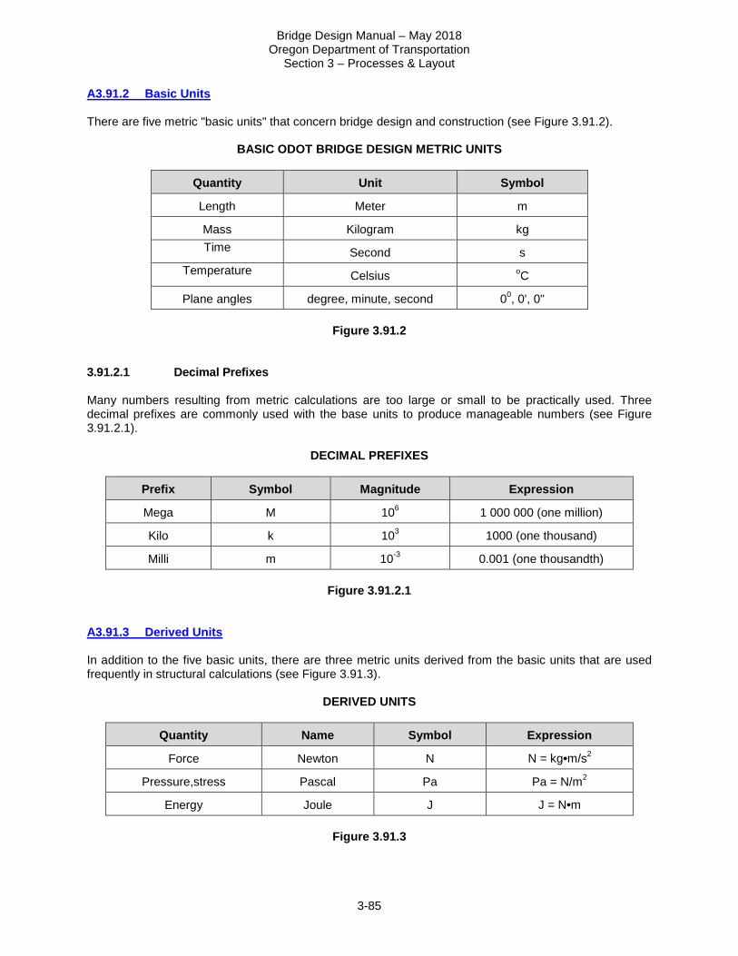
Bridge Design Manual – May 2018 Oregon Department of Transportation
Section 3 – Processes & Layout
3-85
A3.91.2 Basic Units There are five metric "basic units" that concern bridge design and construction (see Figure 3.91.2).
BASIC ODOT BRIDGE DESIGN METRIC UNITS
Quantity Unit Symbol
Length Meter m
Mass Kilogram kg Time Second s
Temperature Celsius oC
Plane angles degree, minute, second 00, 0', 0"
Figure 3.91.2 3.91.2.1 Decimal Prefixes Many numbers resulting from metric calculations are too large or small to be practically used. Three decimal prefixes are commonly used with the base units to produce manageable numbers (see Figure 3.91.2.1).
DECIMAL PREFIXES
Prefix Symbol Magnitude Expression
Mega M 106 1 000 000 (one million)
Kilo k 103 1000 (one thousand)
Milli m 10-3 0.001 (one thousandth)
Figure 3.91.2.1 A3.91.3 Derived Units In addition to the five basic units, there are three metric units derived from the basic units that are used frequently in structural calculations (see Figure 3.91.3).
DERIVED UNITS
Quantity Name Symbol Expression
Force Newton N N = kg•m/s2
Pressure,stress Pascal Pa Pa = N/m2
Energy Joule J J = N•m
Figure 3.91.3

Bridge Design Manual – May 2018 Oregon Department of Transportation
Section 3 – Processes & Layout
3-86
3.91.3.1 Force In order to perform metric calculations properly, it is important to understand the distinction between mass "kg" and force "N". In the metric system, there are separate units for mass "kg" and force "N". Mass indicates the quantity of matter in an object. Force or "force of gravity" is the acceleration due to gravity the object experiences in a particular environment. The mass must be converted to force before computing structural reactions, shears, moments, or internal stresses. Force "N" = mass times acceleration due to gravity. The metric acceleration of gravity on the earth's surface is 9.807 m/s2 (i.e., 32.2 ft/s2 x 0.3048 m/ft). One newton = one kilogram x (one meter)/(one second)2. For example, a simply supported beam 10 meters long with a mass of 1000 kg/m would have a total mass of 10 000 kg (see Figure 3.91.3.1). However, the dead load or force on a beam, on the earth's surface, used to calculate the reactions, shears, moments, etc. would be 1000 x 9.807 = 9807 N/m. The distinction between mass and force in structural calculations is very important.
Quantity Inch-Pound Units Metric Units
Dead Load (Force)
= 672+135 = 807 lb/ft = (1000+201) (9.807) = 11 777.8 N/m
VA = wl/2 = (807)(32.808)/2 = 13,238 lb
= (11 777.8) (10)/2 = 58 889 N
MB = wl2/8 = (807)(32.808)2/8 = 108,578 ft-lb
= (11 777.8)(10)2/8 = 147 222 N•m
FB = M/s = (108,578)(12in/ft)/440 = 2961 psi
=(147 222)(109mm3/m3)/7210x103 = 20 419 000 Pa = 20 419 kPa = 20.419 MPa
Note: lb is understood to be lb-force.
Figure 3.91.3.1 3.91.3.2 Stress The pascal is not universally accepted as the only unit of stress. Because steel section properties are expressed in millimeters, it may be more convenient to express stress in a derivative of pascals; that is in newtons per square millimeter (1 N/mm2 = 1 MPa ).

Bridge Design Manual – May 2018 Oregon Department of Transportation
Section 3 – Processes & Layout
3-87
3.91.3.3 Energy Although the joule is a standard metric unit, it is typically not used in structural design. Moments are always expressed in terms of Nm, or the derivative kN•m. A3.91.4 Metric Conversion Factors Figure 3.91.4, is intended to provide common conversion factors and show typical equivalent conversion units between "inch-pound" and "metric" values. The factors will allow the designer to get a feel for the magnitude of metric units as compared to inch-pound units.
COMMON METRIC UNITS AND CONVERSIONS
Quantity From Inch-Pound Units To Metric Units Multiply by Length mile
foot inch
km m
mm
1.609 344 0.304 8
25.4 Area square mile
acre square yard square foot
square inches
km2 m2 m2 m2
mm2
2.590 00 4 046.87
0.836 127 4 0.092 903 0
645.160 Volume cubic yard
cubic foot m3 m3
0.764 555 0.028 316 8
Mass* Lb Ton
kg kg
0.453 592 0.907 184
Mass/unit length* Plf kg/m 1.488 16 Mass/unit area* Psf kg/m2 4.882 43 Mass density* Pcf kg/m3 16.018 5
Force Lb metric kg
kip
N kN kN
4.448 22 9.806 65 4.448 22
Force/unit length Plf Klf
n/m kN/m
14.593 9 14.593 9
Pressure, stress, Modulus of elasticity
Psf ksf psi ksi
Pa kPa kPa MPa
47.880 3 47.880 3 6.894 76 6.894 76
Bending moment, torque, moment of force
ft-lb ft-kip
N•m kN•m
1.355 82 1.355 82
Moment of inertia in4 mm4 416 231 Section modulus in3 mm3 16 387.064
Temperature oF oC 5/9 (oF - 32) *Note: The Inch-Pound Units system using "a mass which weighs such and such pounds" and converting to true Metric Units masses.
Figure 3.91.4

Bridge Design Manual – May 2018 Oregon Department of Transportation
Section 3 – Processes & Layout
3-88
A3.91.5 Metric Procedural Rules 3.91.5.1 Writing Metric Symbols and Names • Unit symbols should be in lower case except for newton (N), pascal (Pa), and mega (M). • Unit names should always be printed in lower case, i.e., newton, pascal, kilogram. • Do not use the plural of unit symbols (write 45 kg, not 45 kgs), but do use the plural of written unit
names (several kilograms). • Leave a space between the numeral and a unit symbol. Write "70 kg" or "30 oC", not "70kg" or
"30oC". • Do not use a period after the symbol. Write "70 kg", not "70 kg., except when it comes at the end of a
sentence. • Indicate the product of two or more units in symbolic form by using a dot between the symbols, i.e.,
N•m or kg•m. • Do not mix names and symbols. Write N•m or newton meter, not N•meter or newton•m. • Do not leave a space between a decimal prefix and a unit symbol. Write "MPa" or "kN•m", not "M Pa"
or k N•m". 3.91.5.2 Writing Numbers • Use decimals, not fractions. Write 0.75 m, not 3/4 m. • Use a zero before the decimal point for values less than one. Write 0.65 kg, not .65 kg. • Spaces are frequently used to separate blocks of three digits either side of the decimal point. Never
use a comma to separate the blocks. For plan dimensions, it will be acceptable to either insert or omit the space. Write 16 387.064 or 16387.064; but never 16,387.064.
3.91.5.3 Conversions and Rounding When converting from inch-pound units to metric units, round the metric value to the same number of digits as there were in the inch-pound number, i.e., 235.75 lb x 0.453 592 kg/lb = 106.9343 kg which should be rounded to 106.93 kg. Also see ASTM E380, Section 5, for general guidelines. A3.91.6 Bridge Plan and Preparation Guidelines 3.91.6.1 Plan Dimensions For dimensions and elevations use: • Millimeters in standard drawings and structural details. • Meters for plan dimensions (structure and span lengths, structure width, lane and shoulder widths,

Bridge Design Manual – May 2018 Oregon Department of Transportation
Section 3 – Processes & Layout
3-89
etc.) and other long dimensions. • Meters to three places for elevations, preceded with the abbreviation El. (e.g., El. 309.564). To eliminate the repetitive use of (mm) and (m), these will not be used for dimensions in millimeters and elevations in meters. Meter dimensions should be followed by the symbol (m). The following note should be shown on the plans, "All dimensions are in millimeters (mm) and all elevations are in meters (m), except as noted.". At all locations in notes, etc. use (mm) and (m) notations. 3.91.6.2 Reinforcing Steel A new series of soft converted reinforcing steel sizes should be used. Figures 3.91.6.2A and 3.91.6.2B on the following page show the metric properties for conventional and prestressing steel. The equivalent area in square inches is shown for comparison purposes. The metric bar size is roughly equal to the bar diameter in millimeters. The length of straight bars should be shown in 100 millimeter increments where possible. Bent bars should be detailed to the nearest 20 millimeter total length. 3.91.6.3 Fasteners Fasteners are to be called out as a soft conversion to the nearest 0.1 mm. Use the appropriate English specifications for bolts, nuts and washers. 3.91.6.4 Structural Steel The structural steels called out in ODOT plans and specifications all have metric equivalents. These equivalent specifications have the same number (AASHTO or ASTM) followed by a capital M; e.g. AASHTO M 270M or ASTM A 709M. Structural steel shapes will be a soft conversion. AISC conversion tables are available. Plate thickness should be a soft conversion and called out to the nearest 0.1 mm. Normally plate widths should be a hard metric conversion. In some situations it may be appropriate to use soft converted plate widths. If repetitious pieces have a dimension that can use a common English plate width, one plate cut can be avoided and it will be more economical to fabricate the item.

Bridge Design Manual – May 2018 Oregon Department of Transportation
Section 3 – Processes & Layout
3-90
REINFORCING BAR COMPARISON
Metric Bar
English Bar
English Dia. (in)
English Area (in2)
English Weight (lb/ft)
Metric Dia.
(mm)
Metric Area
(mm2)
Metric Mass (kg/m)
#10 #3 0.375 0.11 0.376 9.5 71 0.560
#13 #4 0.500 0.20 0.668 12.7 129 0.994
#16 #5 0.625 0.31 1.043 16.0 199 1.552
#19 #6 0.750 0.44 1.502 19.1 284 2.235
#22 #7 0.875 0.60 2.044 22.2 387 3.042
#25 #8 1.000 0.79 2.670 25.4 510 3.973
#29 #9 1.128 1.00 3.400 28.7 645 5.060
#32 #10 1.270 1.27 4.303 32.3 819 6.404
#36 #11 1.410 1.56 5.313 35.8 1006 7.907
#43 #14 1.693 2.25 7.650 43.0 1452 11.38
#57 #18 2.257 4.00 13.60 57.3 2581 20.24
Figure 3.91.6.2A Stock Bar Lengths
• #10 – 6.09 and 12.19 m • #13 & # 16 – 6.09, 9.14 and 12.19 m • #19 thru #36 – 18.28 m • #43 thru #57 – 18.28, 21.33 and 24.38 m
PRESTRESSING STEEL - Conversion of prestressing steel should be a soft conversion using the table below. Make sure standard drawings and plan detail sheets specify the correct strand diameters.
SEVEN WIRE, UNCOATED STRAND (270 Grade Low-Relaxation AASHTO M203 (ASTM A-416))
Metric Size (mm)
English Size
(inch)
Metric Ult. (kN)
English Ult. (lbs)
Metric Area
(mm2)
English Area (in2)
Metric Mass (kg/m)
English Weight (lb/ft)
9.53 3/8 102.3 23,000 54.84 0.085 0.432 0.290
11.11 7/16 137.9 31,000 74.19 0.115 0.582 0.390
12.70 1/2 183.7 41,300 98.71 0.153 0.775 0.520
15.24 0.600 260.7 58,600 140.0 0.217 1.102 0.740
Figure 3.91.6.2B

Bridge Design Manual – May 2018 Oregon Department of Transportation
Section 3 – Processes & Layout
3-91
A3.91.7 Miscellaneous Common Conversions
Inch-Pound Metric
Dead Loads: Future Wearing Surface 25 psf 1.2 kN/m2 Reinforced Concrete 150 pcf 23.6 kN/m3 Soil 120 pcf 18.9 kN/m3 Material Strengths: Concrete (f'c) 3300 psi 22.8 MPa, Equiv. to 25 MPa 4000 psi 27.6 MPa, Equiv. to 30 MPa 4500 psi 31.0 MPa, Equiv. to 35 MPa 5000 psi 34.5 MPa, Equiv. to 35 MPa 5500 psi 37.9 MPa, Equiv. to 40 MPa 6000 psi 41.4 MPa, Equiv. to 45 MPa 6500 psi 44.8 MPa, Equiv. to 45 MPa 7000 psi 48.3 MPa, Equiv. to 50 MPa Reinforcing Steel: Grade 40 40 ksi 275.8 MPa, Equiv. to 300 MPa Grade 60 60 ksi 413.7 MPa, Equiv. to 420 MPa Grade 80 80 ksi 551.6 MPa, Equiv. to 550 MPa Structural Steel: Grade 36 36 ksi 248.2 MPa, Equiv. to 250 MPa Grade 50 50 ksi 344.7 MPa, Equiv. to 345 MPa Grade 70 70 ksi 482.6 MPa, Equiv. to 480 MPa Reinforcing Steel Clearances 1.0 in 25 mm 1.5 in 40 mm 2.0 in 50 mm 2.5 in 65 mm 3.0 in 75 mm 4.0 in 100 mm Aggregate sizes 1-1/2 in 37.5 mm 1 in 25.4 mm 3/4 in 19.0 mm 3/8 in 9.5 mm Deck Concrete 4500 psi Equivalent to Class 30 (4350 psi) End Panel Concrete 3300 or 4500 psi Equivalent to Class 25 (3626 psi) or
30 (4350 psi) Minor Structure Concrete 3000 psi Class 20 (2901 psi)