table of contents installation instructions
TRANSCRIPT
Installation Instructions
Ritenery International, LLC
Table of Contents
Position template and mark drill points ............ 2
Drill holes and mortise for latch face ................ 3
Install Outside Trim ............................................ 4
Install Inside Trim............................................... 5
Install Outside Escutcheon ................................ 6
Install Inside Escutcheon ................................... 7
Install Strike Plate .............................................. 8
Test Lock ............................................................ 9
Troubleshooting................................................. 9
How to Remove Outside Lever ........................ 10
How to Change Cylinder (if required) .............. 10
How to Adjust for Door Thickness ................... 11
How to Replace IC Core ................................... 11
List of Parts ...................................................... 12
Template .......................................................... 14

2 Installation Instructions | ritelock.com
Figure 1 Positioning the Template
Position template and mark drill
points
Measure and mark the horizontal centerline of the lever (the centerline for the chassis hole) on the door and door jamb. Mark the vertical centerline of the door edge.
Fold the template on the dashed line and carefully place it in position on the high side of the door bevel as shown in Figure 1. Looking through the hole from the opposite side of the door, align the template so that you see the template outline of the 2 1/8″ diameter chassis hole.
Tape the template to the door.
Center punch the necessary drill points. Refer to the instructions on the template.
Note: For steel frame applications, align the template’s horizontal centerline for the latch with the horizontal centerline of the frame’s strike preparation.

3 Installation Instructions | ritelock.com
Drill holes and mortise for latch
face
Drill the holes listed below: chassis hole
◆2 1/8″ diameter
◆through door Stud holes
◆5/16″ diameter
◆through door latch hole
◆1″ diameter
◆meets chassis hole anti-rotational notches, .
◆1/8”x1/8” ◆1/8” deep notches on both side of door
motor wire channel
◆1”x1/8”
◆1/8” deep on inside of the door
Note 1: To locate the center of a hole on the opposite side of the door, drill a pilot hole completely through the door. Note 2: For holes through the door, it is best to drill halfway from each side of the door to prevent the door from splintering.
Install latch
Install the latch in the door as shown in Figure 2.
Check that the door swings freely.
Note: The latch tube prongs should be centered and should project into the chassis hole.
Figure 2. Drilling holes and install latch

4 Installation Instructions | ritelock.com
Figure 3. Install Outside Trim
Figure 4.
Install Outside Trim Feed motor wire into the lock body
hole from outside of door Install lock body into cross-bore hole
from outside of the door (locked side) Lock body must engage both the
latch unit prongs and tail piece (as shown in Figure 4.)
5 Installation Instructions | ritelock.com
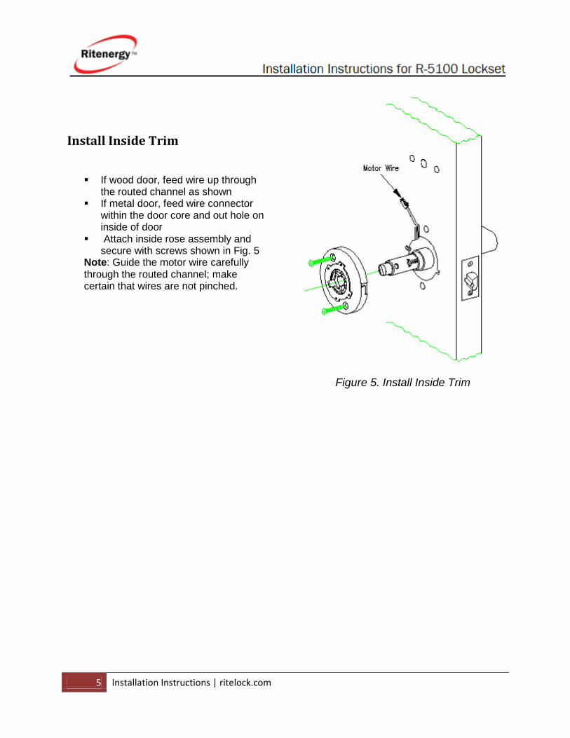
Install Inside Trim
If wood door, feed wire up through the routed channel as shown
If metal door, feed wire connector within the door core and out hole on inside of door
Attach inside rose assembly and secure with screws shown in Fig. 5
Note: Guide the motor wire carefully through the routed channel; make certain that wires are not pinched.
Figure 5. Install Inside Trim

6 Installation Instructions | ritelock.com
Fig. 6 Install Outside Escutcheon
Install Outside Escutcheon
From the outside of the door, feed keypad wires through center hole (1/2”) into the inside of the door.
Insert the escutcheon studs through two 5/16” holes

7 Installation Instructions | ritelock.com
Install Inside Escutcheon Carefully guide the wire into the
inside escutcheon through the center channel. Make certain that wires are not pinched by obstructions in escutcheon
Place inside escutcheon flat against the door
Secure inside escutcheon with two #8-32 x 1 1/4” flat head screw thru interior of inside escutcheon and into post of exterior escutcheon
Straighten escutcheon and tighten the round head screw
Install Inside Door Handle
Place (4) AA battery Holder into the compartment as indicated inside escutcheon
Attach back cover to inside escutcheon and secure with #8-32 x 3/8" security screw
DO NOT OVER TIGHTEN
Fig. 7 Install Inside Escutcheon

8 Installation Instructions | ritelock.com
Fig 8 Install Strike Plate
Install Strike Plate
In alignment with the center of the
latch bolt, mortise the door jamb to
fit the strike box and strike plate.
Drill the holes for the screws used to install the strike plate.
Secure the strike with the two screws provided.
Check the position of the deadlocking plunger against the strike plate.
Caution: The deadlocking plunger of the latch bolt must make contact with the strike plate, as shown in Figure 8. The plunger deadlocks the latch bolt and helps prevents someone from forcing the latch open when the door is closed.

9 Installation Instructions | ritelock.com
Test Lock
Rotate inside lever to test for latch
bolt retraction Place key into cylinder and rotate
key for latch bolt retraction Tighten latch bolt screws on edge of
door Test keypad operation per manual's
instructions
Press 12345#
The green light will flash once and unlock.
Turn the outside lever and open the door.
If the mechanism doesn’t unlock, remove
the back cover and check for proper
orientation and seating of the batteries or
motor connector. Ensure that wires are not
pinched.
Reset the electronics by unplug the battery
pack, press and hold any numeric key for 10
seconds and release. Plug the battery pack
back on, within 5 seconds press and hold #
key. The system will go through a self-test
and flash red and beeps six times.
Troubleshooting

10 Installation Instructions | ritelock.com
How to Remove Outside Lever 1. Insert key, rotate 45° (1/4 Turn) clockwise
and hold 2. Depress lever retainer with push pin tool
(provided) 3. Pull off lever
How to Change Cylinder (if required) 1. With outside lever in hand use standard pliers; pull out cylinder retainer 2. Remove key and cylinder from lever 3. Insert new cylinder 4. Secure by pressing cylinder retainer
Problems Solutions Levers pull off
1. Lever catch not engaging. Lock may not be centered or door is too thick.
2. Cylinder retainer not flush.
3. Non-standard sized cylinder.
4. Outside rose located improperly.
Outside lever
removable without
using key
1. Tailpiece installed in wrong orientation.
2. Wrong tailpiece.
Latch won't retract
1. Incorrect retractor/latch engagement or alignment.
2. Poor door preparation or misalignment thru-bolts.
Key binds in lock
1. Lever catch not fully engaged.
2. Check for proper tailpiece.
Key cannot be removed from cylinder
1. Key in Wrong Position
2. Wrong tailpiece
alignment.

11 Installation Instructions | ritelock.com
How to Adjust for Door Thickness 1. Disassemble the outside lever and remove the outside rose assembly 2. Adjust the door thickness by turning the outside plate by hand
Note: The Lock Is Factory-Packed For 1 ¾” Thick Door
How to Replace IC Core 1. Insert the control key into the core and rotate the key 15 degrees

12 Installation Instructions | ritelock.com
to the right.
2. Pull the key to extract the core
List of Parts
Item Part Number Description Quantity
1 10-1001 Outside escutcheon & keypad 1
1A 10-1001A Keypad assembly only 1

13 Installation Instructions | ritelock.com
1B 10-1001B iButton Prob 1
2 10-1002 Outside Lever (Standard) 1
2A 10-1002A Outside Lever For Best SFIC 1
3 10-1003 Outside Rose Assembly 1
4 10-1004 Outside Plate 1
5 10-1005 Motorized Lock Chassis (Standard) 1
5A 10-1005A Motorized Lock Chassis For Best SFIC 1
5B 10-1005B Motorized Lock Chassis For Thick Door 1
6 10-1006 Inside Plate 1
7 10-1007 Inside Rose Assembly 1
8 10-1008 Screw #10-32UNFx1 5/8” L 2
9 10-1009 Inside escutcheon assembly 1
10 10-1010 Inside Lever 1
11 10-1011 Screw PH FL HD 8-32 X 1 ½” 2
12 10-1012 Waterproof Battery Case 1
13 10-1013 Back Cover Plate 1
14 10-1014 Flat head screw (security) 1
15 10-1015 2-3/4" Backset latch (standard) 1
15A 10-1015A 2-3/8" Backset latch 1
16 10-1016 Screw PH FL HD 2
17 10-1017 Strike Plate 1
18 10-1018 Screw PH FL HD 2

14 Installation Instructions | ritelock.com
Template