table of contentschapter 10 workplace design hfds 2003 10.2.1 sit, sit-stand, and stand consoles the...
TRANSCRIPT

Table of contents 10 Workstation and Workplace design ...................................................................................... 10-1
10.1 General.......................................................................................................................... 10-1 10.2 Workstations and consoles............................................................................................ 10-2
10.2.1 Sit, sit-stand, and stand consoles............................................................................ 10-3 10.2.2 Seated workstations ............................................................................................... 10-5 10.2.3 Horizontal wrap-around console alternatives ...................................................... 10-10 10.2.4 Vertical stacked segments for consoles ............................................................... 10-11 10.2.5 Design and arrangement of multi-person consoles.............................................. 10-12 10.2.6 Standing workstations.......................................................................................... 10-16 10.2.7 Work surfaces ...................................................................................................... 10-19 10.2.8 Storage ................................................................................................................. 10-20 10.2.9 Workstations for maintenance repair ................................................................... 10-20 10.2.10 Workspace for positions other than seated or standing ..................................... 10-20
10.3 Workplace layout ........................................................................................................ 10-22 10.3.1 Equipment and workstation layout ...................................................................... 10-22 10.3.2 Work space features designed into equipment..................................................... 10-24
10.4 Design of passageways ............................................................................................... 10-26 10.4.1 Walkways and traffic areas.................................................................................. 10-26 10.4.2 Wheelchair accessible routes ............................................................................... 10-27 10.4.3 Ground and floor surfaces.................................................................................... 10-29 10.4.4 Landings............................................................................................................... 10-30 10.4.5 Catwalks, tunnels, and crawl spaces .................................................................... 10-30 10.4.6 Platforms, elevators, inclinators........................................................................... 10-30
10.4.6.1 Platforms ....................................................................................................... 10-30 10.4.6.2 Portable platforms......................................................................................... 10-31 10.4.6.3 Platform guardrails, toeholds, screens, and handholds ................................. 10-31 10.4.6.4 Elevators, and hydraulically operated platforms .......................................... 10-33
10.4.7 Entrances and exits .............................................................................................. 10-33 10.4.7.1 General.......................................................................................................... 10-33 10.4.7.2 Doorways and hinged doors.......................................................................... 10-34 10.4.7.3 Alternative door rules ................................................................................... 10-35 10.4.7.4 Emergency doors .......................................................................................... 10-36 10.4.7.5 Hatches.......................................................................................................... 10-37 10.4.7.6 Whole body access........................................................................................ 10-37
10.4.8 Ramps, ladders, and stairs.................................................................................... 10-39 10.4.8.1 General.......................................................................................................... 10-39 10.4.8.2 Pedestrian ramps ........................................................................................... 10-43 10.4.8.3 Stairs ............................................................................................................. 10-44 10.4.8.4 Stair ladders .................................................................................................. 10-46 10.4.8.5 Fixed ladders................................................................................................. 10-48 10.4.8.6 Portable ladders............................................................................................. 10-50
Glossary ................................................................................................................................... 10-53 References ............................................................................................................................... 10-54 Index ........................................................................................................................................ 10-55
List of exhibits Exhibit 10.2.1.1 (a) Standard console dimensions.................................................................... 10-3 Exhibit 10.2.1.1 (b) Standard console illustration and dimension key ..................................... 10-4 Exhibit 10.2.2.2 Seated workspace dimensions and illustrations ............................................. 10-7 Exhibit 10.2.2.13 Swing-away seat for short-term use............................................................. 10-9 Exhibit 10.2.3 Example of horizontal wrap-around console .................................................. 10-10 Exhibit 10.2.4 Examples of vertical stacked segments........................................................... 10-11 Exhibit 10.2.5.1 Basic and variations of multi-person console arrangements with an example
control room arrangement................................................................................................ 10-14
10-i

Exhibit 10.2.5.2 Concepts of functional reach arc and equidistant visual arc for a stand console.......................................................................................................................................... 10-15
Exhibit 10.2.6.1 Standing workstation illustration and dimensions ....................................... 10-17 Exhibit 10.2.6.2 Control and display placement limits for vertical and stand consoles where see
over capabilities are not required..................................................................................... 10-18 Exhibit 10.2.10.1 Dimensions and illustrations for workspaces other than seated or standing.......
.......................................................................................................................................... 10-21 Exhibit 10.3.2.4 Access space through integral design. ......................................................... 10-25 Exhibit 10.4.1.2 Walkway and passageway............................................................................ 10-27 Exhibit 10.4.2.6 Minimum clearance point for a single wheelchair. ...................................... 10-28 Exhibit 10.4.2.7 Dimensions for making a U-turn in a wheelchair. ....................................... 10-29 Exhibit 10.4.7.2.1 Door dimensions ....................................................................................... 10-34 Exhibit 10.4.7.6.1 Whole body access dimensions................................................................. 10-38 Exhibit 10.4.8.1.2 Type of structure in relation to angle of ascent ......................................... 10-39 Exhibit 10.4.8.1.12 Critical dimensions for ramps. ................................................................ 10-41 Exhibit 10.4.8.1.15 Combined ramp and stairs....................................................................... 10-43 Exhibit 10.4.8.3.1 Design requirements for stair dimensions................................................. 10-44 Exhibit 10.4.8.4.1 Design requirements for stair ladders ....................................................... 10-46 Exhibit 10.4.8.5.1 Design requirements for fixed ladders ...................................................... 10-48 Exhibit 10.4.8.5.3 Design requirements for fixed ladder cage dimensions ............................ 10-49 Exhibit 10.4.8.6.1 (a) Design requirements for portable step ladders. ................................... 10-50 Exhibit 10.4.8.6.1 (b) Design requirements for portable rung ladders. ................................. 10-51
10-ii

Chapter 10 Workplace design HFDS 2003
10 Workstation and Workplace design This chapter deals with the design criteria associated with workstations and workplaces. A workstation is a place designed for a specific task or activity from where work is conducted or operations are directed. Desks, offices, repair benches, tools, equipment, and computer terminals are examples of these special accommodations and equipment. Workstations are designed as areas for one or more workers to use in accomplishing purposeful tasks or jobs. A workplace is defined as an area room or establishment where work is done. The chapter is organized so as to start from the design of a single workstation then broaden to multiple workstations and workplaces. The following design criteria affect systems, equipment, and facility design. Compliance will help enhance the performance of FAA personnel. Some of the rules address the interaction of maintenance and operational activities.
10.1 General 10.1.1 Design for human activities. Workplace and associated
equipment designs shall systematically incorporate the effects of tasks, performance capabilities, physical dimensions, and viewing dimensions for maintainers and for operators. [Source: National Aeronautics and Space Administration (NASA-STD-3000A), 1989] 10.1.2 Physical accommodation. The physical dimensions of
workplaces and equipment shall conform to the anthropometric and biomechanical characteristics of the specific population of users for whom the system is being designed and to the characteristics of the tasks to be performed. Anthropometric and biomechanical data are found in Chapter 14. [Source: NASA-STD-3000A, 1989]
Examples. Those areas that deal with clearance dimensions that a large portion of the user population could be expected to use frequently or in a life threatening situation require as a minimum the 99th percentile value for clearance. Heavy traffic passageways and normal doorway clearances are examples. Similarly, the 1st percentile values for reach and strength are used as limiting dimensions. These values ensure that the smallest personnel can reach and open escape mechanisms. In most other cases, the convention of designing for the 5th through 95 percentile is used for practical design related reasons. Male and female personnel are included in the anthropometric data. The higher percentile values are often dominated by male data and the lower values by female data (see Chapter 14 and its references for treatments of anthropometric practice).
10.1.3 Work space to permit access. Space for maintenance access
shall be designed into systems and equipment. [Source: Department of the Air Force (AFSC DH 1-3), 1980]
10-1

HFDS 2003 Chapter 10 Workplace design
10.1.4 Maintenance independence. Workplaces, controls, and
displays that are associated with maintenance activities should be separate from operator workplaces, controls, and displays. [Source: NASA-STD-3000A, 1989]
10.1.5 Maintenance and operations interference. Maintenance activities should not interfere with ongoing operator tasks. [Source: NASA-STD-3000A, 1989]
10.1.6 Redundant information. Where maintenance activities would interfere and where simultaneous activities are necessary, redundant information should be provided to the operators for their ongoing diagnostic and emergency maintenance responsibilities. [Source: NASA-STD-3000A, 1989]
10.1.7 Visibility of displays and controls. Controls and displays that are solely for maintenance should be readily accessible when needed by maintenance personnel without being visible to the operators. [Source: NASA-STD-3000A, 1989] 10.1.8 Task and general illumination of work space. Illumination
for maintenance shall include general area illumination and task illumination. Refer to Chapter 13 for detailed illumination design criteria. [Source: NASA-STD-3000A, 1989] 10.1.9 Illumination for normal operations and maintenance.
Where simultaneous operations and maintenance activities are necessary, workplace illumination for maintenance activities shall be compatible with illumination requirements for operators' visual tasks. [Source: NASA-STD-3000A, 1989] 10.1.10 Illumination for critical operations and maintenance.
Where it is critical, the design shall ensure that adequate maintenance illumination shall not interfere with operator visual tasks. [Source: NASA-STD-3000A, 1989] 10.1.11 Special information and communications interfaces.
Workspace and interfaces for accessing maintenance information systems and maintenance communications systems shall be provided where these special maintenance linkages are appropriate in the design of the system. [Source: NASA-STD-3000A, 1989]
Example. Remote maintenance subsystems that include computers, terminals, modems, and networks provide special links to maintenance information and communications systems.
10.2 Workstations and consoles Standard console designs are addressed in this section. Recommended configurations for sit, sit-stand, and stand consoles are given, and horizontal wrap-around and vertically stacked segment alternatives are provided. Additional consoles for teams that monitor ongoing processes are addressed in this section.
10-2

Chapter 10 Workplace design HFDS 2003
10.2.1 Sit, sit-stand, and stand consoles The rules that follow are to be used to gain the benefits and potential cost savings inherent in standard consoles, units, and racks. In some cases, planned usage may necessitate unique design solutions.
Discussion. The task performance of a user working with consoles is influenced by 1) the contours and slopes of the console panels, 2) the parallax in viewing displays, 3) the location of displays and controls, and 4) the adequacy of the space to support the console operator.
10.2.1.1 Dimensions for console configurations. Exhibit
10.2.1.1(a) lists five types of consoles for individuals and gives dimensions for alternative standard configurations. Selected configurations should conform to the dimensions listed and illustrated in Exhibit 10.2.1.1(b). [Source: Department of Defense (MIL-HDBK-759B), 1992]
Exhibit 10.2.1.1 (a) Standard console dimensions Maximum Suggested Writing surface Seat height Maximum total console vertical shelf height from standing console height from dimension from surface at width standing of panel standing midpoint (not surface (with sills) surface of G shown) Type of console mm (in) mm (in) mm (in) mm (in) mm (in) A B C D - 1. Sit (with vision 1170 (46.0) 520 (20.5) 650 (25.5) 435 (17.0) 1120 (44.0) over the top)* 1335 (52.5) 520 (20.5) 810 (32.0) 595 (23.5) 1120 (44.0) 1435 (56.5) 520 (20.5) 910 (36.0) 695 (27.5) 1120 (44.0) 2. Sit (without 1310 (51.5) 660 (26.0) 650 (25.5) 435 (17.0) 910 (36.0) vision over top) 1470 (58.0) 660 (26.0) 810 (32.0) 595 (23.5) 910 (36.0) 1570 (62.0) 660 (26.0) 910 (36.0) 695 (27.5) 910 (36.0) 3. Sit-stand (with 1535 (60.5) 620 (24.5) 910 (36.0) 695 (27.5) 910 (36.0) standing vision over top) 4. Stand (with 1535 (60.5) 620 (24.5) 910 (36.0) NA NA 1120 (44.0) vision over top) 5. Stand (without 1830 (72.0) 910 (36.0) 910 (36.0) NA NA 910 (36.0) vision over top) * The range in “A” is provided to allow latitude in the volume of the lower part of the console; note relationship to “C” and “D.”
10-3

HFDS 2003 Chapter 10 Workplace design
Exhibit 10.2.1.1 (b) Standard console illustration and dimension key
10-4

Chapter 10 Workplace design HFDS 2003
10.2.1.2 Selection of a standard console. Each console configuration should be selected to accommodate the following task-related variables: a. visibility over the top of console,
b. user mobility (e.g., sit, sit-stand, or stand requirements),
c. control and display demand for panel space (for example, display legibility, control accessibility),
d. volume of space necessary for leg room and essential equipment beneath the writing surface, and
e. communications demands of the tasks. [Source: Department of Defense (MIL-STD-1472D), 1989]
10.2.2 Seated workstations In this section, a discussion to help exploit the advantages of the seated position is followed by general rules for ensuring seating compatibility with tasks. The section includes rules for office seating design and for seat cushion, armrest, and footrest design. Temporary swing away seats are also treated. Vehicles and moving platform seats are not addressed in this document. Designers can exploit the following advantages of seated positions: a. Seated positions reduce workload by helping maintain the
body position and carry body weight.
b. Seats provide comfortable positions that promote long-term focused attention on activities and information in the nearby workspace.
c. Seating can help establish stability to accommodate fine eye-hand coordination tasks.
d. Seating can be designed to accommodate powerful exertions on pedals.
e. Seated workers have more accessibility to equipment and are able to move about to reduce fatigue and boredom,
f. Seating can be designed to swivel and move on rollers to extend visual, reach, and communications access. [Source: MIL-HDBK-759B, 1992]
The main disadvantages of seated work positions are that seated workers can apply less arm force and smaller arm movements than standing workers. In addition, seating limits reach with both arms and hands.
10-5

HFDS 2003 Chapter 10 Workplace design
10.2.2.1 Swivels and rollers. For most jobs and tasks that do not
require heavy work and where seated positions are appropriate, swivel capability and caster rollers should be provided for seat ingress and egress and task performance throughout the workplace. [Source: MIL-HDBK-759B, 1992]
10.2.2.2 Seating dimensions. General seated workplace dimensions are given and illustrated in Exhibit 10.2.2.2. Seat designs and selections should meet or exceed minimum values, provide adjustment ranges and fixed and preferred values when these are compatible with the population and tasks to be performed. [Source: MIL-HDBK-759B, 1992; MIL-STD-1472D, 1989]
10-6

Chapter 10 Workplace design HFDS 2003
10-7
Exhibit 10.2.2.2 Seated workspace dimensions and illustrations

HFDS 2003 Chapter 10 Workplace design
10.2.2.3 Knee space height. The preferred knee space, as shown in Exhibit 10.2.2.2, should be 640 mm (25 in) in height. [Source: MIL-HDBK-759B, 1992]
Discussion. A footrest will increase the needed knee space.
10.2.2.4 Attaining knee space. Where equipment packaging permits, knee space and associated leg space should be attained by sloping the console surface under the working or writing surface. [Source: MIL-HDBK-759B, 1992]
10.2.2.5 Seat cushioning. Seats should be cushioned whenever workers must remain seated for more than an hour at a time, or for more than 20% of their working time. [Source: MIL-HDBK-759B, 1992]
10.2.2.6 Seat cushioning features. Good seat cushioning should a. have flat, firm shape with enough softness to deform,
b. have resilient material under the cushion to absorb shocks,
c. support body weight, primarily around the two bony points of the pelvis,
d. tilt backward 5-7 degrees so the seat (rather than the user's muscles) supports the back,
e. be shaped to follow the inward curve of the lower back and provide adequate support for it to relieve strain of the back muscles,
f. avoid applying pressure under the thighs,
g. incorporate perforated or ventilated materials to prevent hotness or sweating, and
h. allow the sitter to shift positions. [Source: MIL-HDBK-759B, 1992]
Discussion. Larger cushioned backrests are best because a larger support area provides the user more opportunities to change position.
10.2.2.7 The use of armrests. Workplace seating should provide
armrests so that the elbows can support some upper body weight, unless the rests would be incompatible with the tasks. [Source: MIL-HDBK-759B, 1992; MIL-STD-1472D, 1989]
10.2.2.8 Undercut armrests. Armrests should be undercut to allow space for the hips and thighs. Exhibit 10.2.2.2 provides fixed armrest dimensions. [Source: MIL-HDBK-759B, 1992; MIL-STD-1472D, 1989]
10-8

Chapter 10 Workplace design HFDS 2003
10.2.2.9 Removable or adjustable armrests. Removable or
adjustable armrests should be considered when removal is necessary for some primary tasks. The preferred adjustable range is from 190 to 280 mm (7.5 to 11 in) above the compressed seat surface and at least 200 mm (8 in) in length. [Source: MIL-HDBK-759B, 1992; MIL-STD-1472D, 1989]
10.2.2.10 Support arm for tracking control. When seated tasks include the use of a tracking control for frequent or continuous control, the armrest should support the worker's arm in the same plane as the control. [Source: MIL-HDBK-759B, 1992; MIL-STD-1472D, 1989]
10.2.2.11 Footrests. Whenever workers must sit for extended periods in seats higher than 460 mm (18 in) or work with work surfaces higher than 760 mm (30 in), they should have a footrest. [Source: MIL-HDBK-759B, 1992]
Explanation. Footrests can provide support and add to comfort for seated jobs. They may be attached to the chair or separate items positioned on the floor.
10.2.2.12 Separate footrests. When footrests are separate items,
they should not be allowed to interfere with traffic. [Source: MIL-HDBK-759B, 1992]
10.2.2.13 Temporary seats. Where space limitations and task frequency warrant, a temporary swing away seat should be provided with preferred dimensions of 380 mm (15 in) diameter, 460 mm (18 in) floor to seat top dimension with an adjustability of plus or minus 50 mm (2 in). Exhibit 10.2.2.13 illustrates a swing away seat. [Source: MIL-HDBK-759B, 1992]
Exhibit 10.2.2.13 Swing-away seat for short-term use
10-9

HFDS 2003 Chapter 10 Workplace design
10.2.3 Horizontal wrap-around console alternatives Whenever the panel space required for a seated console user exceeds that recommended in Exhibit 10.2.1.1 (a) providing standard console dimensions, the special purpose horizontal wrap-around console presented in this section may be used. The concept for this alternative is illustrated in Exhibit 10.2.3. Exhibit 10.2.3 Example of horizontal wrap-around console
10.2.3.1. Panel width. When requirements for preferred panel space for the user exceed a panel width of 1.12 m (44 in), a flat-surface, segmented, wrap-around console should be provided. [Source: MIL-STD-1472D, 1989]
Discussion. This panel facilitates placing controls within the reach of the 5th percentile users.
10.2.3.2 Panel angles. The left and right segments should be placed
at an angle, measured from the frontal plane of the central segment, so that these segments can be reached by the 5th percentile stationary operator. [Source: MIL-STD-1472D, 1989] 10.2.3.3 Central segment dimensions with vision over the top.
Where vision over the top is required (thereby limiting vertical panel space), the width of the central segment shall not exceed 1.12 m (44 in). [Source: MIL-STD-1472D, 1989]
10.2.3.4 Left and right segment dimensions with vision over the top. Where vision over the top is required (thereby limiting vertical panel space), the left and right segments should not exceed 610 mm (24 in). [Source: MIL-STD-1472D, 1989] 10.2.3.5 Width dimensions without vision over the top. Where
vision over the top is not required (that is, where the total console height exceeds the seat height by more than 690 mm [27 in]), the width of the central segment shall not exceed 860 mm (34 in). [Source: MIL-STD-1472D, 1989]
10-10

Chapter 10 Workplace design HFDS 2003
10.2.3.6 Left and right segment dimensions without vision over
the top. Where vision over the top is not required (that is, where the total console height exceeds the seat height by more than 690 mm [27 in]), and that of the left and right segments should not exceed 610 mm (24 in). [Source: MIL-STD-1472D, 1989] 10.2.3.7 Viewing angle. The total required left-to-right viewing
angle shall not exceed 190 degrees. [Source: MIL-STD-1472D, 1989]
10.2.3.8 Reduction of viewing angle. The required left-to-right viewing angle should be reduced whenever possible through appropriate control-display layout. [Source: MIL-STD-1472D, 1989]
10.2.4 Vertical stacked segments for consoles Another alternative special-purpose console applies to the case where seeing over the top is not required and lateral space is limited. The concept for this individual seated user console is shown in Exhibit 10.2.4. Exhibit 10.2.4 Examples of vertical stacked segments
10.2.4.1 Panel division. Where direct forward vision over the top of the console is not required by a seated person and where lateral space is limited, the panel shall be divided into three vertical stacked segments whose surfaces are perpendicular to the operator's line of sight when the head is moved up or down slightly. [Source: MIL-STD-1472D, 1989]
Discussion. Locating screens above resting eye level can cause the user to adopt uncomfortable or awkward positions, leading to pain. To avoid this, only infrequently used information ought to be located in the upper tiers segments of the consoles. For additional information on display location, see Chapter 5, Displays and printers.
10-11

HFDS 2003 Chapter 10 Workplace design
10.2.4.2 Height. The center of the central segment should be 800 mm (31.5 in) above the seat reference point and not exceed 530 mm (21 in). [Source: MIL-STD-1472D, 1989]
10.2.5 Design and arrangement of multi-person consoles When a team must monitor, diagnose, or control a large ongoing process or operation, many arrangements of consoles are possible. Exhibit 10.2.5.1 shows several basic console arrangements, variations on the basic arrangements, and an example of a multi-unit control room which incorporates supervisory visual access. This section offers rules for selecting among alternative console arrangements and console designs. 10.2.5.1 Selecting arrangements for team consoles. Several
primary and support factors shall be used in selecting among alternative team console arrangements (see Exhibit 10.2.5.1). The factors to be used are listed in (a) through (q).
Discussion. Primary factors for team console arrangements, (a) through (l), are those that directly involve and impact the ongoing process and mission of the system. Secondary or support factors, (m) through (q), are off-line to the direct process monitoring or control but may influence the layout and design of team consoles.
a. functions and resultant tasks for personnel, hardware, and
software components that are necessary for process monitoring and controlling (these functions and tasks must cover normal, degraded, and emergency modes of system operations),
b. necessary team communication interactions and team links with external command and control components of the system,
c. numbers of personnel necessary to handle the expected high workload levels,
d. common viewing requirements and individual visual access requirements,
e. maintenance access for control or processing subsystems,
f. supervisory viewing requirements, ongoing supervisory process control responsibilities, supervisory space and access requirements, and supervisory information and communications requirements,
g. management, maintenance, and operating concepts and policies,
h. architectural and facility engineering constraints,
i. requirements and space constraints associated with primary equipment, controls and displays, computer, printout or readout devices, and closed-circuit monitoring devices,
10-12
Chapter 10 Workplace design HFDS 2003
j. illumination, acoustic, and environmental requirements associated with primary tasks,
k. primary work surface areas for writing and reading,
l. primary storage areas and surfaces for documents, procedures, tools, spares, and supplies,
m. secondary supervisor office privacy requirements,
n. security requirements,
o. visitor provisions and traffic areas,
p. personnel conveniences such as restrooms, kitchen, snack, drinking water, and personal belonging storage, and
q. support storage for additional documentation and other housekeeping needs. [Source: Electric Power Research Institute (EPRI NP-36591), 1984]
10-13

HFDS 2003 Chapter 10 Workplace design
Exhibit 10.2.5.1 Basic and variations of multi-person console arrangements with an example control room arrangement
10-14

Chapter 10 Workplace design HFDS 2003
10.2.5.2 Selecting team console types and designs. Selection and
design of individual team position consoles should be made among standard sit, sit-stand, and stand consoles (see Section 10.2.1), free standing consoles, built-in vertical wall consoles, and specially configured consoles based upon the factors that follow: a. functions and tasks allocated to the types of personnel and
position(s) associated with the console,
b. visual access required for common control display areas that may determine the required see-over characteristics,
c. position communication requirements,
d. personnel mobility requirements,
e. reach and visual access areas for consoles (Exhibit 10.2.5.2 shows reach and visual legibility arcs for console design),
f. work surface area requirements,
g. requirements to share information, displays, controls, or work surfaces with adjacent positions,
h. the postures required for monitoring and controlling, as well as the durations that such postures must be maintained, and
i. the need for consoles and information standardization across system functions and locations to reduce training and to facilitate interoperability. [Source: EPRI NP-36591, 1984]]
Discussion. In accomplishing the design layout, the designer needs to consider the criticality, durations, and frequency of control and display interactions, as well as the legibility and accuracies required.
Exhibit 10.2.5.2 Concepts of functional reach arc and equidistant visual arc for a stand console
10-15

HFDS 2003 Chapter 10 Workplace design
10.2.6 Standing workstations Standing workstations are used for routine, frequent, or short term jobs or tasks for which the worker needs to be able to face different directions or to move from one position to another. The designer can exploit the following advantages of a standing position when they are compatible with the tasks to be performed: a. When standing, workers can apply more muscular arm force
and make larger arm movements than when seated. These forces may be applied to levers or valves.
b. Standing workers can move to see and use components in areas that would be inaccessible to seated users.
c. Standing workers can move about to reduce fatigue and boredom.
d. Standing workers can use flat working surfaces without knee room, thus saving space.
e. A standing workstation is not as dimensionally constrained as that of the seated operator. Equipment that standing operators view or adjust may be placed anywhere around them as long as it is at the proper height.
Discussion. If the worker is not free to move about, or if the task and attention demands are concentrated so that the worker remains in one position, the workstation should be designed so the worker can sit or take a sit-stand position. The main disadvantage of the standing position is that the worker's physical workload is increased because one constantly has to carry one's own weight and stabilize and balance one's body.
10.2.6.1 Standing workstation and workbench dimensions. The
dimensions of standing workstations and workbenches should meet the minimum and not exceed the maximum preferred values in Exhibit 10.2.6.1 and, when required, provide for adjustments to accommodate the 5th through the 95th percentile of the worker population. [Source: MIL-HDBK-759B, 1992]
10-16

Chapter 10 Workplace design HFDS 2003
Exhibit 10.2.6.1 Standing workstation illustration and dimensions
Work benches Standard type A1. Height 91 cm (36 in) above floor B1. Width 99 cm (39 in) above floor Podium type A2. Height 104 cm (41 in) above floor B2. Width 91 cm (36 in) above floor Work clearances Minimum Preferred Arctic C. Passing body (mm) 330 380 380 depth (in) 13 15 15 D. Standing space (mm) 760 910 - (in) 30 36 - E. Foot space (mm) 100X100 - - (in) 4X4 - - F. Overhead (mm) 1855 2030 1930 clearance (in) 73 80 76 G. Maximum (mm) - 685 635 overhead reach (in) - 27 25 H. Maximum depth (mm) - 585 585 of reach (in) - 23 23
10.2.6.2 Control and display placement on stand consoles. Prime
controls and displays on stand consoles (including CRT displays) should be located in the prime areas and within the boundaries noted in Exhibit 10.2.6.2, which illustrates control and display placement limits for those vertical and stand consoles where see-over capabilities are not required. [Source: EPRI NP-36591, 1984]
10-17

HFDS 2003 Chapter 10 Workplace design
Exhibit 10.2.6.2 Control and display placement limits for vertical and stand consoles where see over capabilities are not required.
10-18

Chapter 10 Workplace design HFDS 2003
10.2.6.3 Hardwired display placement. Hardwired displays, including annunciator displays, should be located horizontally within 45 degrees of the operator's eye reference point with CRT displays restricted to within 35 degrees. [Source: EPRI NP-36591, 1984]
10.2.6.4 Control and display placement on stand consoles. On consoles where a discrete task sequence of display and control actions is appropriate for a single user's actuation, the sequenced displays and controls should not exceed 1.8 m (72 in) in width so reach and visual access can be accommodated. [Source: EPRI NP-36591, 1984]
Explanation. The actual display limits on the console will depend upon the distance from which the worker views the console displays. The illustration at the bottom of Exhibit 10.2.6.2 shows a 1.8 m (72 in) dimension as the maximum lateral spread for a discrete task at normal viewing distance.
10.2.6.5 Special team sit-stand console minimum vertical height.
When a sit-stand console requires a see-over capability, the vertical height of the console should be no higher than 1.40 m (55 in). [Source: EPRI NP-36591, 1984]
Explanation. Where a sit-stand desk surface of at least 410 mm (16 in) deep and 610 mm (24 in) wide is provided, 760 mm (30 in) is preferred.
10.2.6.6 Special team sit-stand console minimum vertical height.
Desk height should be 910 to 960 mm (36 to 38 in) high so that the seated eye height can be about the same as the standing eye height. [Source: EPRI NP-36591, 1984]
10.2.6.7 Special team sit-stand console seat dimensions. The seat should be adjustable up to 760 mm (30 in) in seat cushion height and have a 460 mm (18 in) diameter footrest located at a constant 460 mm (18 in) below the seat cushion. [Source: EPRI NP-36591, 1984] 10.2.6.8 Kickspace. All cabinets, consoles, and work surfaces that
require an operator or maintainer to stand or sit close to their front surfaces shall contain a kick space at the base of the front surfaces of at least 100 mm (4 in) deep and 100 mm (4 in) high. [Source: MIL-STD-1472D, 1989]
10.2.7 Work surfaces 10.2.7.1 Work surfaces for standing positions. Work surfaces shall
be consistent with the needs of jobs and tasks. Surfaces for standing work shall be 915 mm plus or minus 15 mm (36 in plus or minus .6 in) from the floor. Where machine parts or equipment are manipulated, the surface shall be at least 760 mm (30 in) wide. In all cases, the work surface shall be at least 407 mm (16 in) deep. This lateral depth may be increased based upon the demands of the job. [Source: MIL-STD-1800A, 1990]
10-19

HFDS 2003 Chapter 10 Workplace design
10.2.7.2 Work surfaces for seated positions. Surfaces for seated
operations shall be 740 - 790 mm (29 - 31 inches) above the floor. Width and depth shall be the same as in Paragraph 10.2.2.3.1. [Source: MIL-STD-1800A, 1990]
Discussion. For light precision work, work surface height can be increased within the above limits. For work requiring increased force, the work surface height can be lower.
10.2.7.3 Writing surfaces. Writing surfaces shall be at least 610 mm
(24 in) wide and 407 mm (16 in) deep. [Source: MIL-STD-1800A, 1990] 10.2.7.4 Task sizing of work surfaces. When a work surface is used
for more than one task, the surface dimensions for tasks requiring the most space shall be used. [Source: MIL-STD-1800A, 1990]
10.2.8 Storage 10.2.8.1 Storage space. Adequate space for storage of manuals,
worksheets, test equipment, tools, and other materials that are required for use by operational or maintenance personnel shall be provided on consoles and, where appropriate, on equipment. [Source: MIL-STD-1472D, 1989]
10.2.9 Workstations for maintenance repair 10.2.9.1 Sizing. Maintenance repair workstations shall be large
enough to handle the largest equipment or component that will require repair. [Source: NASA-STD-3000A, 1989] 10.2.9.2 Special equipment. Maintenance repair workstations shall
be designed to accommodate general purpose, specific purpose, and automated diagnostic and test equipment appropriate to the expected maintenance tasks. [Source: NASA-STD-3000A, 1989]
10.2.10 Workspace for positions other than seated or standing Maintenance work requiring unusual working positions is to be avoided through design. Dimensions for workspace other than seated or standing are illustrated in this section. 10.2.10.1 Workspace clearance dimensions. When personnel must
work in or pass through limited spaces, the clearances shall meet or exceed the minimum values given and illustrated in Exhibit 10.2.10.1. [Source: MIL-HDBK-759B, 1992]
10-20

Chapter 10 Workplace design HFDS 2003
Exhibit 10.2.10.1 Dimensions and illustrations for workspaces other than seated or standing
Supine workspace
Minimum Preferred Artic clothed
A Height 510mm (20in)
610mm (24in)
660mm (26in)
B Length 1860mm (73in)
1910mm (75in)
1980mm (78in)
Squatting workspace
Minimum Preferred Artic clothed
C Height 1220mm (48in)
-- 1290mm (51in)
D Width 685mm (27in)
910mm (36in)
--
Optimum display area
685mm (27in)
1090mm (43in)
--
Optimum control area
485mm (19 in)
865mm (34in)
Stooping workspace
Minimum Preferred Artic clothed
E Width 660mm (26in)
1020mm (40in)
1120mm (44in)
Optimum display area
810mm (32in)
1220mm (48in)
Optimum control area
601mm (24in)
990 mm (39in)
Kneeling workspace
Minimum Preferred Artic clothed
F Width 1060mm (42in)
1220mm (48in)
1270mm (50in)
G Height 1420mm (56in)
-- 1500mm (59in)
H Optimum work point
-- 685mm (27in)
--
Optimum display area
510mm (20in)
890mm (35in)
--
Optimum
control area 510mm (20in)
890mm (35in)
--
Kneeling crawl space
Minimum Preferred Artic clothed
I Height 785mm (31in)
910mm (36in)
965mm (38in)
J Length 1500mm (59in)
-- 1760mm (69in)
Prone work or crawl space
Minimum Preferred Artic clothed
K Height 430mm (17in)
510mm (20in)
610mm (24in)
L Length 2860mm (113in)
-- --
10-21

HFDS 2003 Chapter 10 Workplace design
10.3 Workplace layout
10.3.1 Equipment and workstation layout
10.3.1.1 Traffic areas. Traffic area and traffic flow design should be based upon a. a consideration of task-based activities in and around
workstations,
b. location of workstations and traffic areas so that they interfere minimally with each other,
c. a consideration of the necessary movements of equipment in the work and traffic areas,
d. a consideration of normal traffic conditions, worst cases, and emergency conditions, and
e. a consideration of means by which to avoid collisions and to maximize traffic efficiency. [Source: NASA-STD-3000A, 1989]
10.3.1.2 Layout to minimize traffic and congestion. Equipment
and workstations shall be located so as to minimize congestion in workflow or worker movement and to minimize interference with and from personnel traffic areas. [Source: NASA-STD-3000A, 1989]
10.3.1.3 Equipment grouping by maintenance needs. Equipment and components maintained by the same technician should be grouped together so the technician will not have to move around in checking or working on the equipment. [Source: MIL-STD-1472D, 1989; MIL-HDBK-759B, 1992; AFSC DH 1-3, 1980]
10.3.1.4 Equipment grouping. Equipment should be grouped so that no other type of technician has to remove equipment or components before the proper technician can obtain access to make replacements or repairs. [Source: MIL-STD-1472D, 1989; MIL-HDBK-759B, 1992; AFSC DH 1-3, 1980]
Example. Components that require frequent visual inspection of check points, adjustment points, cable-end connection, and labels should be located in positions that can be seen easily.
10.3.1.5 Equipment arrangements for groups of workers. When
groups of two or more people need to be located within a work space, the groups and their equipment shall be arranged so that equipment can be shared, communications requirements can be minimized, necessary face-to-face communications and coordination are facilitated, mutual interference is minimized, and supervision is simplified. [Source: MIL-STD-1472D, 1989]
10-22

Chapter 10 Workplace design HFDS 2003
10.3.1.6 Layout for safety. All equipment and components should
be located to minimize the possibility of equipment damage, personnel injury, or inadvertent actuation. [Source: MIL-HDBK-759B, 1992; AFSC DH 1-3, 1980] 10.3.1.7 Criticality. The most critical units (based on mission,
functions, and tasks) shall be located so as to be most accessible. [Source: MIL-STD-1472D, 1989; NASA-STD-3000A, 1989] 10.3.1.8 Frequency. Where criticality is not a factor, units expected
to require more total use (either more frequent and longer durations of use) shall be more accessible. [Source: MIL-STD-1472D, 1989; NASA-STD-3000A, 1989] 10.3.1.9 Floor space for work and passage. Floor space shall be
planned and designed to ensure the following: (a-f are required by 29 CFR 1910.22) a. floor space for work areas and for aisle space do not occupy
the same space and, thus, the work and passage do not interfere,
b. material and equipment handling tasks are to be used in sizing work and aisle spaces; necessary turning space for materials and equipment is included,
c. the work and aisle space can be kept clean,
d. storage space for material and equipment does not interfere with work or passage,
e. floor work and aisle space are free of protruding nails, splinters, holes, loose boards, or other loose materials,
f. permanent aisles and passageways are appropriately marked,
g. floor loading limits are conspicuously displayed to prevent structural overloading,
h. floor space around electrical utilization equipments is provided in accordance with Paragraph 12.4.1.18, (Design and location of electrical installations and electrical utilization equipment), and
i. free floor space of at least 1.2m (4 ft) is to be provided in front of each equipment rack. [Source: MIL-STD-1472D, 1989; MIL-STD-1800A, 1990]
10.3.1.10 Spacing in front of racks and cabinets. Clearance from
the front of a rack to the nearest facing surface or obstacle shall be at least 1.07 m (42 in). [Source: MIL-STD-1472D, 1989] 10.3.1.11 Spacing between racks and cabinets. The minimum
space between rows of cabinets containing drawers shall be 200 mm (8 in) greater than the depth of the deepest drawer. [Source: MIL-STD-1472D, 1989]
10-23

HFDS 2003 Chapter 10 Workplace design
10.3.1.12 Lateral work space. The minimum lateral work space for racks having drawers or removable equipment shall be as follows (measured from the drawers or equipment in the extended position): a. For racks having drawers of removable items weighing less
than 20 kg (44 lb), allow 460 mm (18 in) on one side and 100 mm (4 in) on the other, and
b. For racks having drawers or removable items weighing over 20 kg (44 lb), allow for two person access (one on each side): 460 mm (18 in) on each side. [Source: MIL-STD-1472D, 1989; MIL-STD-1800A, 1990]
10.3.1.13 Rear access space. When a maintainer is to have access to
the back of an entire rack or panel-mounted unit, the unit shall be installed with sufficient clearance to permit the maintainer to perform all required maintenance tasks, including the removal of the rear panel(s). [Source: AFSC DH 1-3, 1980]
10.3.1.14 Maintenance independence. Workplaces, controls, and displays that are associated with maintenance activities should be separate from operator workplaces, controls, and displays. [Source: NASA-STD-3000A, 1989; MIL-STD-1472D, 1989]
Discussion. Controls and displays that are solely for maintenance should not be visible to operators but should be readily accessible when needed by maintenance personnel.
10.3.2 Work space features designed into equipment 10.3.2.1 Work space to permit access. Space for maintenance
access shall be designed into the systems and equipment. [Source: AFSC DH 1-3, 1980]
Discussion. Accessibility is influenced by system maintenance concepts, procedures, and tasks. [Source: AFSC DH 1-3, 1980
10.3.2.2 Access space for effective maintenance. Equipment shall
be designed to allow effective maintenance by providing sufficient space for maintenance personnel to access the equipment and components permitting maintainers with 95th percentile values on task related dimensions to have sufficient access and space to perform the maintenance tasks and to use the tools necessary for the tasks. [Source: AFSC DH 1-3, 1980]
Example. Where maintenance is to be performed at the equipment location, equipment design can include techniques that use the chassis as an integral part of the structure of the equipment, for example, pull out drawers or shelves. These techniques ensure that all components can be reached with a minimum of access space. (See also Chapter 4, Designing equipment for maintenance.
10-24

Chapter 10 Workplace design HFDS 2003
10.3.2.3 Reach limits. Reach limits shall permit the 5th percentile maintainer access to perform the tasks with the appropriate tools. [Source: AFSC DH 1-3, 1980]
10.3.2.4 Access openings. Access openings should be provided on at least three sides of equipment as illustrated in Exhibit 10.3.2.4, which illustrates the space required for three-sided access with hinged doors versus that required for integral pullout drawers. [Source: AFSC DH 1-3, 1980]
Discussion. Equipment with panels or hinged access doors may need to be removed before the equipment can be maintained or serviced. Less room is generally required to work on equipment with pull out shelves or drawers than on equipment with access doors or panels. Built in pullout shelves and drawers are preferred to hinged doors or removable panels.
Exhibit 10.3.2.4 Access space through integral design. [Source: AFSC DH 1-3, 1980]
10.3.2.5 Component locations for access. Components to be serviced, replaced, or repaired on the equipment should be placed in a plane parallel to and within 150 mm (6 in) of the access openings when hinged doors or removable panels are used. [Source: AFSC DH 1-3, 1980] 10.3.2.6 Ease of replacement. Each unit of equipment and its
components shall be designed and installed to ensure ease of replacement. [Source: AFSC DH 1-3, 1980]
10.3.2.7 Access interference. Each unit should be located so that no other units or equipment need to be removed to reach it. [Source: AFSC DH 1-3, 1980] 10.3.2.8 Equipment location to reduce access interference. Units
of equipment shall not be located in recesses, behind, or under structural members or other equipment components where access or removal is difficult. [Source: AFSC DH 1-3, 1980]
10-25

HFDS 2003 Chapter 10 Workplace design
10.3.2.9 Access to equipment covers. Technicians shall be able to open unit covers without interference from bulkheads, brackets, or other equipment. [Source: AFSC DH 1-3, 1980] 10.3.2.10 Visual access. Units shall be located so that check points,
adjustment points, connectors, and labels face the technician and are not hidden by other units. [Source: AFSC DH 1-3, 1980] 10.3.2.11 Clear visual inspection. Units and components that
require frequent visual inspection shall be located so that items being inspected (for example, desiccators or fuses) can be seen easily without removal of panels, covers, or other units. [Source: AFSC DH 1-3, 1980]
10.3.2.12 Front removal. Units of equipment should be designed for removal of components and, if applicable, subordinate units, through the front rather than the back of the equipment. [Source: AFSC DH 1-3, 1980]
10.4 Design of passageways In complex systems and facilities, passageways are necessary for personnel to be able to get to equipment areas and works stations. These personnel may be required to carry tools and to move equipment through passageways including over steps and through entrances. This subsection covers traffic area walkways; special spaces such as catwalks (to be avoided when possible); platforms and elevators; entrances and exits; and ramps, stairs, and ladders.
Definitions. Passageways for the purpose of this document are areas across which people must pass for work purposes. Walkways are areas designated for walking; corridors are walkways that are physically restricted by walls or the like.
10.4.1 Walkways and traffic areas 10.4.1.1 Corridor width. Corridor widths shall be designed for the
peak traffic load expected, for traffic directions, and for the number of entrances and exits in the area. [Source: MIL-HDBK-759B, 1992]
10-26

Chapter 10 Workplace design HFDS 2003
10.4.1.2 Corridors. To allow personnel to move with tolerable
restrictions, the widths of corridors shall equal or exceed those given in Exhibit 10.4.1.2 (see Paragraph 10.4.7.4.1 for OSHA implications when a corridor is designated as part of an emergency egress). [Source: MIL-HDBK-759B, 1992]
Exhibit 10.4.1.2 Walkway and passageway
10.4.1.3 Added clearance. Adequate clearance should be allowed for personnel wearing bulky clothing and carrying equipment. [Source: MIL-HDBK-759B, 1992]
Example. A person can move through a corridor 510 mm (20 in) wide with some difficulty; however, a one-person corridor for bulky clothes and comfortable travel should be at least 760 mm (30 in) wide (see Exhibit 10.4.1.2). The dimensions of equipment to be carried or transported may add width to these minimum and preferred values.
10.4.1.4 Floors. Passageway floors shall be stable, firm and slip
resistant. [Source: Uniform Federal Accessibility Standard (UFAS), 1988]
10.4.2 Wheelchair accessible routes 10.4.2.1 Minimum accessible routes. At least one accessible route
within the boundary of the site shall be provided from public transportation stops, accessible parking, accessible passenger loading zones, and public streets or sidewalks to the accessible building entrance they serve. [Source: UFAS, 1988]
10-27

HFDS 2003 Chapter 10 Workplace design
10.4.2.2 Protruding objects. Protruding objects shall not reduce the clear width of an accessible route or maneuvering space. [Source: UFAS, 1988] 10.4.2.3 Connecting routes to other areas. At least one accessible
route shall connect accessible buildings, facilities, elements, and spaces that are on the same site. [Source: UFAS, 1988] 10.4.2.4 Connecting entrances to other areas. At least one
accessible route shall connect accessible building or facility entrances with all accessible spaces and elements and with all accessible units within the building or facility. [Source: UFAS, 1988] 10.4.2.5 Width. The minimum clear width of an accessible route for
a single wheelchair shall be 32 in (815mm) at a point and 36 in (915 mm) continuously. [Source: UFAS, 1988] 10.4.2.6 Making a 90 degree turn around an obstruction. When a
person in a wheelchair must make a 90 degree turn around an obstruction, the minimum clear width of the accessible route shall be a 36 in (915 mm) wide passage into another 36 inch (915 mm) passage if the depth of each leg is a minimum of 48 inches (1220 mm) on the inside dimensions of the turn, as shown in Exhibit 10.4.2.6. [Source: UFAS,1988] Exhibit 10.4.2.6 Minimum clearance point for a single wheelchair. [Source: UFAS, 1988]
10.4.2.7 Making a U-turn in a wheelchair. When a person in a
wheelchair must make a U-turn, the space provided should at minimum be 1965 mm (78 in) by 1525 mm (60 in) as shown in Exhibit 10.4.2.7. [Source: ADAAG, 1998]
10-28

Chapter 10 Workplace design HFDS 2003
Exhibit 10.4.2.7 Dimensions for making a U-turn in a wheelchair. [Source: UFAS, 1988]
10.4.2.8 Passing Space. When an accessible route has less than 60
in (1525 mm) clear width, then passing spaces at least 60 in by 60 in (1525 mm by 1525 mm) shall be located at reasonable intervals not to exceed 200 ft (61 m). [Source: UFAS, 1988]
Discussion. A T-intersection of two corridors or walks is an acceptable passing place. [Source: UFAS, 1988]
10.4.2.9 Slope. An accessible route with a running slope greater
than 1:20 is a ramp and shall comply with Section 10.4.8 (Ramps, ladders, and stairs). [Source: UFAS, 1988] 10.4.2.10 Maximum slope. Nowhere shall the cross slope of an
accessible route exceed 1:50. [Source: UFAS, 1988] 10.4.2.11 Exclusion of stairs, steps, and escalators. An accessible
route shall not include stairs, steps, or escalators. [Source UFAS, 1988] 10.4.2.12 Egress. Accessible routes serving any accessible space or
element shall also serve as a means of egress for emergencies or connect to an accessible area of rescue assistance. [Source: UFAS, 1988]
10.4.3 Ground and floor surfaces 10.4.3.1 Floors. Passageway floors shall be provided with nonskid
or other high friction surfaces. [Source: MIL-HDBK-759B, 1992]
10-29

HFDS 2003 Chapter 10 Workplace design
10.4.4 Landings 10.4.4.1 Level landings. Ramps shall have level landings at bottom
and top of each ramp and each ramp run. [Source: MIL-HDBK-759B, 1992] 10.4.4.2 Width. The landing shall be at least as wide as the ramp
run leading to it. [Source: MIL-HDBK-759B, 1992; UFAS, 1988] 10.4.4.3 Length. The landing length shall be a minimum of 60 in
(1525 mm) clear. [Source: MIL-HDBK-759B, 1992; UFAS, 1988] 10.4.4.4 Ramp changes directions. If ramps change direction at
landings, the minimum landing size shall be 60 in by 60 in (1525 mm by 1525 mm). [Source: MIL-HDBK-759B, 1992; UFAS, 1988]
10.4.5 Catwalks, tunnels, and crawl spaces Catwalks, tunnels, and crawl spaces are specialized facility features used to accommodate unique space or environmental limitations that preclude normal corridors or walkways. 10.4.5.1 Minimum catwalk width. The minimum catwalk floor
width shall be 460 mm (18 inches) to accommodate walking one foot in front of the other and carrying tools or equipment. [Source: VanCott & Kinkade, 1972] 10.4.5.2 Enclosed space ventilation. Enclosed catwalks, tunnels, and
crawl spaces shall have adequate air ventilation to sustain their maximum permissible personnel numbers for an indefinite period. [Source: NASA-STD-3000A, 1989]
Discussion. Consider both temperature and air quality when determining adequate air ventilation. [Source: NASA-STD-3000A, 1989]
10.4.5.3 Movement or work without mechanical aid. When special
passageways require bending, stooping, or crawling, personnel with 99th percentile dimensions shall be able to accomplish the movement and, where applicable, work without the assistance of other people or of mechanical aids. [Source: NASA-STD-3000A, 1989]
10.4.6 Platforms, elevators, inclinators
10.4.6.1 Platforms 10.4.6.1.1 Hands free work area. Platform design shall permit both
of the users hands to be free for work. [Source: MIL-HDBK-759B, 1992] 10.4.6.1.2 Guardrails. Guardrails shall be provided in accordance
with Section 10.4.6.3 (Platform guardrails, toeholds, screens, and handholds). [Source: MIL-HDBK-759B, 1992]
10-30

Chapter 10 Workplace design HFDS 2003
10.4.6.1.3 Permissible gaps with equipment. Platform design shall provide a continuous closure between the equipment and the platform with average conformation within 50 mm (2 in); avoiding gaps greater than 150 mm (6 in). [Source: MIL-HDBK-759B, 1992] 10.4.6.1.4 Protect equipment surface. Contact plates, cushions,
bumpers, or pads shall be used, as necessary, to protect the equipment surfaces. [Source: MIL-HDBK-759B, 1992] 10.4.6.1.5 Platform strength. The platform shall have sufficient
strength to hold the worker(s) in addition to the heaviest tools and equipment expected plus a safety factor consistent with design practice for the structural materials. [Source: MIL-HDBK-759B, 1992]
Discussion. Assume 113.4 kg (250 lb) for each person. [Source: MIL-HDBK-759B, 1992]
10.4.6.1.6 Test equipment support. When test equipment will be
used, the design shall provide support for test equipment at the appropriate height for its use. [Source: MIL-HDBK-759B, 1992] 10.4.6.1.7 Open metal grating for exterior platforms and work
area surfaces. Exterior platforms and similar work areas shall be constructed of open metal grating. [Source: MIL-STD-1472D, 1989; MIL-STD-1800A, 1990; MIL-W-5044, 1998; MIL-W-5050, 1998] 10.4.6.1.8 Alternate surfaces for platforms and work area
surfaces. Where grating is impractical and for alternatively constructed interior platforms and work passageways, floor surfaces shall be treated with non-skid material that conforms to MIL-W-5044 and that is applied in accordance with MIL-W-5050. [Source: MIL-STD-1472D, 1989; MIL-STD-1800A, 1990; MIL-W-5044, 1998; MIL-W-5050, 1998]
10.4.6.2 Portable platforms
10.4.6.2.1 Portable platforms. Portable platforms should be lightweight in their material and fully collapsible. [Source: MIL-HDBK-759B, 1992] 10.4.6.2.2 Platform wheels and brakes. Any platform on wheels
shall have brakes and wheel locks. [Source: MIL-HDBK-759B, 1992]
10.4.6.3 Platform guardrails, toeholds, screens, and handholds 10.4.6.3.1 Open sides of personnel platforms. All open sides of
personnel platforms shall be equipped with guardrails, which have at least two rails (an intermediate rail and top rail). [Source: MIL-STD-1472D, 1989] 10.4.6.3.2 Guardrails. The open area of personnel platforms where
work is to be done shall be guarded without interfering with work tasks. [Source: MIL-STD-1472D, 1989]
10-31

HFDS 2003 Chapter 10 Workplace design
10.4.6.3.3 Guardrail dimensions. Guardrail dimensions shall be as
follows: a. top rail height at least 1.1 m (42 in)
b. distance between the platform edge and the centerline of the railing not to exceed 65 mm (2.5 inches)
c. rail diameter between 37 mm (1.5 in) and 75 mm (3 in). [Source: 29 CFR 1910.23, 1985; MIL-STD-1472D, 1989]
Discussion. In accordance with OSHA 29 CFR 1910.23 (e), this railing height and diameter range describe the OSHA standard guard railing for platforms, ramps, floor openings, hatches, and wall openings (that a person could fall into). [Source: 29 CFR 1910.23, 1985; MIL-STD-1472D, 1989]
10.4.6.3.4 Toe board or guard screen. A toe board of 10 cm (4 in)
to 15 cm (6 in) or a guard screen that extends from the floor base to the intermediate rail shall be used to guard floor openings. [Source: MIL-STD-1472D, 1989; MIL-HDBK-759B, 1992]
Note. OSHA 29 CFR 1910.23 (e) permits a 102 mm (4 in) toe board as a minimum.
Discussion. The guard screen is used to prevent a person who falls on the platform from falling from the platform. It can also prevent most tools, parts, and equipment from falling from the platform. Toe boards are intended to prevent tools, parts, and equipment from falling as well as to prevent the worker's foot from slipping off the edge of the platform.
10.4.6.3.5 Handholds. Handholds shall be furnished where needed
to assist in climbing onto a platform or as aids in performing the intended maintenance tasks from the platform. [Source: MIL-STD-1472D, 1989] 10.4.6.3.6 Handholds, guardrails for adverse conditions or
motion. Handholds and guardrails shall be provided where personnel must stabilize themselves because of high winds, ice, fog or other hazards and when working in moving vehicles. [Source: MIL-HDBK-759B, 1992]
10-32

Chapter 10 Workplace design HFDS 2003
10.4.6.4 Elevators, and hydraulically operated platforms
10.4.6.4.1 Elevators, inclinators, and hydraulic work platforms.
Where these passage or work aids are needed, the following operating safety features shall be included: a. Maximum load signs located where they can be easily seen.
b. Guards used to prevent accidental operations of the lift.
c. An easily reachable capability for manually lowering the platform or elevator provided when feasible.
d. Floor surface treatment in accordance with the treatment of open platforms in Paragraph 10.4.6.1.8 (Alternate surfaces for platforms and work area surfaces). [Source: MIL-STD-1472D, 1989; MIL-STD-1800A, 1990]
10.4.6.4.2 Designed-in safety features. The following designed-in features shall be provided: a. limit stops to prevent injury to personnel and damage to
equipment, and
Definition. Limit stops are mechanical mechanisms designed to restrict a moving object or part by stopping it at predetermined (limit) positions.
b. an automatic fail-safe brake or other self-locking device in
case of lift mechanism failure. [Source: MIL-STD-1472D, 1989]
10.4.7 Entrances and exits This section covers general rules for entrances and exits. Doorways and normal hinged doors for individual and multi-person entry, alternatives to normal hinged doors, emergency doors, hatches, and emergency escape hatches are treated.
10.4.7.1 General
10.4.7.1.1 Entrances for enclosed work areas. Enclosed work areas should have conventional entrances and exits for routine access and to permit unrestricted flow for all anticipated traffic and movements of equipment. [Source: MIL-HDBK-759B, 1992]
10.4.7.1.2 Routine. Conventional entrances and exits for enclosed work areas should be located so that personnel who are entering or leaving will not inadvertently operate or block access to controls or displays or otherwise interfere with ongoing work in the area. [Source: MIL-HDBK-759B, 1992]
10-33

HFDS 2003 Chapter 10 Workplace design
10.4.7.2 Doorways and hinged doors
10.4.7.2.1 Door dimensions. Hinged doors that allow the passage of
one person shall have at least the dimensions shown in Exhibit 10.4.7.2.1. [Source: MIL-STD-1800A, 1990]
Note. If the depicted area is a means of exit, OSHA 29 CFR 1910.37 (h)(2)(i) requires that the floor to ceiling dimension be at least 2.29 m (7.5 ft) and any protrusions from the ceiling be no less than 2.04 m (6.7 ft).
Exhibit 10.4.7.2.1 Door dimensions. [Source: MIL-HDBK-759B, 1992]
10.4.7.2.2 Perpendicular wall door clearances. When a door opens
inward next to a perpendicular wall, a clearance of at least 100 mm (4 in) between the door at the hinge and the plane of the wall shall be provided (see Exhibit 10.4.7.2.1). [Source: MIL-STD-1800A, 1990] 10.4.7.2.3 Equipment or furniture door clearances. Equipment or
furniture shall not be positioned within 2.9 inches of the swing path of a door that opens inward (see Exhibit 10.4.7.2.1). [Source: MIL-STD-1800A, 1990] 10.4.7.2.4 Door opening direction for normal density traffic.
When the normal traffic density and the exiting personnel traffic in emergency conditions are expected to be low, then hinged doors shall open inward rather than outward into a corridor. [Source: MIL-STD-1800A, 1990]
Discussion. Opening inward will prevent injury to personnel using the corridor. [Source: MIL-STD-1800A, 1990]
10.4.7.2.5 Door opening direction for high density traffic. When
exiting traffic volume is expected to be high, the door shall have a see-through window and open outward to ensure the feasibility of exiting in an emergency. [Source: MIL-STD-1800A, 1990]
10-34

Chapter 10 Workplace design HFDS 2003
10.4.7.3 Alternative door rules
10.4.7.3.1 Sliding and folding doors. When horizontal or vertical
sliding or folding doors are used to allow large pieces of equipment or vehicles to pass through, alternative personnel exits should be available. [Source: MIL-STD-1800A, 1990; MIL-HDBK-759B, 1992]
Discussion. Because large doors may jam, provide a hinged door for personnel entrance and exit. If horizontal or vertical sliding or folding doors are the only exits available for personnel to egress the building, provide a hinged door built into the sliding or folding door. [Source: MIL-STD-1800A, 1990; MIL-HDBK-759B, 1992]
10.4.7.3.2 Swinging doors. Swinging doors should be used in pairs,
one for each direction of traffic, with the hinges attached to a center post that separates the doors. [Source: MIL-STD-1800A, 1990; MIL-HDBK-759B, 1992]
10.4.7.3.3 Visual access on swinging doors. Swinging doors should have openings or windows for visual access to oncoming traffic. [Source: MIL-STD-1800A, 1990; MIL-HDBK-759B, 1992]
10.4.7.3.4 Spring mechanisms on swinging doors. A spring mechanism should only be used when the door size or weight prevents manual opening and closing. [Source: MIL-STD-1800A, 1990; MIL-HDBK-759B, 1992]
Discussion. Avoid spring closure mechanisms with a light door as this closing arrangement can be hazardous. [Source: MIL-STD-1800A, 1990; MIL-HDBK-759B, 1992]
10.4.7.3.5 Revolving doors. Revolving doors are hazardous and
should not be used. [Source: MIL-STD-1800A, 1990; MIL-HDBK-759B, 1992]
10.4.7.3.6 Floor to ceiling glass doors or windows. Where floor to ceiling doors or windows are used, the glass area should be patterned or labeled so that users will not mistake it for an unobstructed passageway. [Source: MIL-STD-1800A, 1990; MIL-HDBK-759B, 1992]
10-35

HFDS 2003 Chapter 10 Workplace design
10.4.7.4 Emergency doors
10.4.7.4.1 Space for exit. Emergency exits shall allow enough space
for rapid exit of all occupants, including any who must carry essential equipment or wear bulky clothing without danger of personnel injury or damage to the equipment being carried. [Source: 29 CFR 1910.36-37, 1985; MIL-HDBK-759B, 1992]
Discussion. OSHA 1910.36-37 and National Fire Protection Association codes specify the design requirements for "ways of exit" from buildings and facilities. A designated means of emergency egress requires a minimum of 18 inches of unobstructed "way of exit" travel from any point in a structure to an exterior safe public way. Design requirements for any unobstructed "way of exit" are functions of the nature of the building construction and contents, the maximum occupancy capacities of its components, and the arrangement of designated "ways of exit."
10.4.7.4.2 Emergency door and exit design and construction.
Emergency doors and exits shall be designed and constructed so that they a. are simple to operate,
b. are readily accessible,
c. are clearly designated,
d. are unobstructed,
e. are simple to locate and operate in the dark,
f. are capable of being opened in 3 sec or less,
g. require 44 and 133 N (10 to 30 lbs) of operating force to open,
h. permit exit by one person in 5 sec or less, and
i. do not in themselves, or in their operation, constitute a safety hazard. [Source: MIL-STD-1472D, 1989]
Discussion. A door that is not blocked in the direction of exiting travel is not considered an obstruction. An inside door under low occupancy conditions cannot be less than 71 cm (28 in) in width. For occupancy capacities of 60 to 100 people, the unobstructed minimum widths would range between 76 to 112 cm (30 to 44 in), respectively. When other conditions are considered these minimal dimensions could be larger. If the depicted corridors in Exhibit 10.4.1.2 are designated parts of an emergency "way of exit", the minimal width of the unobstructed way would exclude the swing areas where doors open into the "way of exit."
10-36

Chapter 10 Workplace design HFDS 2003
10.4.7.4.3 Ceiling areas along a means of egress. According to
OSHA 29 CFR 1910.37 (h)(2)(i), ceiling areas along a means of egress (including exterior escape paths) shall be at least 2.29 m (7.5 ft) above the floor and protrusions not be lower than 2.04 m (6.7 ft). [Source: 29 CFR 1910.37, 1985]
10.4.7.5 Hatches 10.4.7.5.1 Flush with surfaces. Where structural considerations
permit, hatches shall be flush with the floor or wall surfaces. [Source: MIL-STD-1800A, 1990] 10.4.7.5.2 Hatch opening motion. Hatches shall open with a single
motion of the hand or foot. [Source: MIL-STD-1800A, 1990] 10.4.7.5.3 Hatch opening and closing forces. When a handle is
used, the unlocking force shall not exceed 90 N (20 pounds). [Source: MIL-STD-1800A, 1990] 10.4.7.5.4 Hatch opening and closing forces. Overhead hatches
shall require no more than 220 N (50 pounds) for opening and closing or not exceed the fifth percentile arm and hand strength of the user population, whichever is less. [Source: MIL-STD-1800A, 1990; MIL-STD-1472D, 1989] 10.4.7.5.5 Clearance dimensions for hatches. Clearance
dimensions for size and passage shall be based upon the 99th percentile values for the expected population and accommodate suitably clothed and equipped maintainers together with any equipment they are expected to carry. [Source: MIL-STD-1472D, 1989] 10.4.7.5.6 Limiting dimensions for hatches. Limiting dimensions
for location and operability shall be based upon the 1st percentile values for females in the expected user population. [Source: MIL-STD-1800A, 1990]
Discussion. Clearance dimensions influence the size for access, accommodation, and entrance by the larger people in the user population. Limiting dimensions permit the smaller people in the user population to reach or view controls and displays and to manipulate latches, handles or accesses.
10.4.7.5.7 Rescue requirements. Where rescue of personnel may be
required, openings shall be large enough to accommodate two suitably clothed rescuers. [Source: MIL-STD-1800A, 1990] 10.4.7.5.8 Rectangular hatch minimums. When rectangular hatches
are used, they shall meet or exceed the minimal whole body dimensions of Exhibit 10.4.7.6.1. [Source: MIL-STD-1800A, 1990]
10.4.7.6 Whole body access 10.4.7.6.1 Whole body access. Dimensions for whole body access
shall meet or exceed those shown in Exhibit 10.4.7.6.1. [Source: MIL-STD-1472D, 1989; MIL-STD-1800A, 1990]
10-37

HFDS 2003 Chapter 10 Workplace design
Exhibit 10.4.7.6.1 Whole body access dimensions. [Source: MIL-STD-1472D, 1989; MIL-STD-1800A, 1990]
Clothing Light Bulky Dimensions A B A B Top and bottom 330 mm 580 mm 410 mm 690 mm access (13 in) (23 in) (16 in) (27 in) Side access 660 mm 760 mm 740 mm 860 mm
10.4.7.6.2 Whole body access with a step down. Where there is a
need to step down through an access and the step distance exceeds 690 mm (27 in), foot rests or steps shall be provided. [Source: MIL-STD-1472D, 1989; MIL-STD-1800A, 1990] 10.4.7.6.3 Emergency escape hatches. Emergency escape hatches
shall accommodate the equipment and clothing that escaping personnel will be carrying and wearing, be clear of all external obstructions, and located to avoid external hazards. [Source: MIL-HDBK-759B, 1992] 10.4.7.6.4 Emergency escape hatch dimensions. The minimum and
preferred dimensions for special emergency escape hatches shall be (1) rectangular minimum: 405 mm by 610 mm (16 in by 24 in), preferred 510 mm by 710 mm (20 in by 30 in); (2) square minimum: 460 mm (18 in), preferred 560 mm (22 in); (3) circular minimum 560 mm (22 in), preferred 710 mm (30 in). [Source: MIL-HDBK-759B, 1992]
10-38

Chapter 10 Workplace design HFDS 2003
10.4.8 Ramps, ladders, and stairs
10.4.8.1 General Rules are provided below for selecting and using structures for making changes in elevation of ramps, stairs, and ladders. Common design criteria for these structures are provided as are detailed rules for ramps, stairs, stair ladders, fixed ladders and portable ladders. Stair ladders have steps rather than rungs. 10.4.8.1.1 Selection of safest. The structure that gives the safest and
most efficient passage shall be selected. [Source: MIL-STD-1800A, 1990; MIL-STD-1472D, 1989; MIL-HDBK-759B, 1992; Department of Energy (UCRL-15673), 1985]
Note. The rules for ramps specified in this section apply to "working" ramps (for example, ramps for forklifts from a dock down to the ground) or those used for purposes other than for wheelchair accesses.
10.4.8.1.2 Selection based on angle. The selection of ramps, stairs,
stair-ladders, or fixed ladders for specific applications shall be based on the angle of ascent required and the critical criteria levels in Exhibit 10.4.8.1.2. [Source: MIL-STD-1800A, 1990; MIL-STD-1472D, 1989; MIL-HDBK-759B, 1992; UCRL-15673, 1985] Exhibit 10.4.8.1.2 Type of structure in relation to angle of ascent.
10-39

HFDS 2003 Chapter 10 Workplace design
10.4.8.1.3 For heavy carrying. The following guidance should be followed when selecting structures over which equipment or tools must be carried: a. Provide ramps, elevators, or equivalent means when
maintainers must carry or transport heavy or bulky equipment.
b. Do not use stairs and steps where the user or maintainer must carry bulky loads or loads in excess of 13 kg (29 lbs).
c. Do not use ladders when users or maintainers carry equipment because both hands should be free to grasp and climb ladders.
Exceptions. Vehicular-boarding ladders are not considered to be stair ladders or fixed ladders. Thus, the rules in Section 10.4.8 do not apply. [Source: MIL-HDBK-759B, 1992]
10.4.8.1.4 Material characteristics. Ramps, stairs, and ladders shall
be constructed of materials that are lightweight, nonconductive, splinter-proof, waterproof, weatherproof, humidity-resistant, and resistant to chemical action. [Source: UCRL-15673, 1985]
Discussion. Take into account the environmental conditions during the design phase, including inclement weather (for example, snow, ice, mud, sand, and wind), if applicable. If de-icing is applicable, design them to be tolerant of hot water or steam de-icing. [Source: UCRL-15673, 1985]
10.4.8.1.5 Carrying strength of the structures. Ramps, stairs, and
ladders shall be designed to withstand the total weight of the largest combination of personnel and carried equipment likely to be on them at one time. [Source: UCRL-15673, 1985]
Note. Multiply these estimates by a safety factor appropriate to the materials used. Use 113.4 Kg (250 lb) per person to estimate personnel weight. [Source: UCRL-15673, 1985]
10.4.8.1.6 Nonskid floor surfaces. Ramps, stairs, and ladders shall
be provided with nonskid surfaces on all areas where personnel are expected to walk or stand to work. [Source: UCRL-15673, 1985] 10.4.8.1.7 Warning labels. Ramps, stairs, and ladders shall have
symbols or placards that warn against any hazards associated with their use, (for example, low overhead obstructions, possible shock, and load limits). [Source: UCRL-15673, 1985] 10.4.8.1.8 Handrails. Ramps, stairs, and ladders shall be equipped
with a handrail on each side. [Source: MIL-STD-1472D, 1989] 10.4.8.1.9 Guardrails. Where personnel could fall into an open area
under a ramp, stair, or ladder handrail, an intermediate level guardrail shall be provided. [Source: MIL-STD-1472D, 1989] 10.4.8.1.10 Proper illumination. Ramps, stairs, and ladders shall be
provided with appropriate illumination (see Chapter 13 (Environment) for illumination criteria). [Source: UCRL-15673, 1985]
10-40

Chapter 10 Workplace design HFDS 2003
10.4.8.1.11 Ramp landings. Ramps shall have level landings at the
top and bottom of each ramp and each ramp run that have the following features: a. the landing at least as wide as the ramp run leading to it,
b. the landing with a minimum length of 1.53 m (60 in) clear,
c. when ramps change direction at landings, a minimum landing size of 1.53 m by 1.53 m (60 in by 60 in), and
d. make the area in front of a doorway located at a landing comply with Section 10.4.7.2. [Source: MIL-HDBK-759B, 1992]
Note. The rules for ramps specified in this section, apply to "working" ramps (for example, ramps for forklifts from a dock down to the ground) or those used for purposes other than for wheelchair accesses.
10.4.8.1.12 Optimum dimensions for ramps. Dimensions for ramps
should conform to the recommended best values for ramps given in Exhibit 10.4.8.1.12. [Source: UCRL-15673, 1985] 10.4.8.1.13 Minimal and maximum dimensions for ramps. In all
cases, dimensions for ramps shall be within the specific minimum and maximum limits shown for ramps given in Exhibit 10.4.8.1.12. [Source: UCRL-15673, 1985] Note. In Exhibit 10.4.8.1.12, the minimal and best handrail height, diameter, and hand clearance comply with OSHA 29 CFR 1910.23 (e).
10-41

HFDS 2003 Chapter 10 Workplace design
Exhibit 10.4.8.1.12 Critical dimensions for ramps. [Source: UCRL-15673, 1985]
Min. Max. Best A Angle of rise - 20° 7-15° B Distance between 23 cm 41 cm 36 cm cleats (9 in) (16 in) (14 in) C Height of 95 cm 107 cm 107 cm handrails (36 in) (42 in) (42 in) D Width 95 cm - - (36 in) E Diameter of 4 cm 8 cm 4 cm handrail (1.5 in) (3 in) (1.5 in) F Clearance around 8 cm - 8 cm handrail (3 in) - (3 in)
10.4.8.1.14 Ramps for pushing or pulling equipment on carts. When ramps are used to push or pull carts, the designer shall stay within human strength capabilities in establishing the angle of inclination. [Source: MIL-HDBK-759B, 1992]
10.4.8.1.15 Combined vehicular or cart and personnel traffic. Stairs should be provided for personnel when vehicles and pedestrians share a ramp and the angle of ramp inclination exceeds 7 degrees. Exhibit 10.4.8.1.15 illustrates a ramp and stairs combination with a pedestrian area on the right side. [Source: MIL-HDBK-759B, 1992]
10-42

Chapter 10 Workplace design HFDS 2003
Exhibit 10.4.8.1.15 Combined ramp and stairs. [Source: MIL-HDBK-759B, 1992]
10.4.8.1.16 Personnel traffic area placement. Personnel traffic
areas should be off to the side or on both sides of the vehicle areas. [Source: MIL-HDBK-759B, 1992]
10.4.8.1.17 Separation of vehicular and personnel traffic areas. Vehicular traffic and walking traffic should be clearly separated by markings and handrails. [Source: MIL-HDBK-759B, 1992]
10.4.8.2 Pedestrian ramps The rules for ramps specified in this section apply to pedestrian ramps. These ramps are intended for pedestrian traffic including those individuals requiring wheelchair access.
10.4.8.2.1 Handrails for ramps. Ramps for pedestrian traffic should have handrails. [Source: MIL-STD-1472D, 1989] 10.4.8.2.2 Nonskid materials for ramps. Nonskid materials should
be used on the floor area of ramps wherever pedestrian traffic is expected. [Source: MIL-STD-1472D, 1989; MIL-HDBK-759B, 1992] 10.4.8.2.3 Cleating of ramps. Where special environmental
conditions require cleating of ramps, cleats should be spaced 360 mm (14 in) apart and run from handrail to handrail at right angles to traffic. [Source: MIL-STD-1472D, 1989; MIL-HDBK-759B, 1992]
Discussion. Cleating of ramps facilitates footing for walking and rolling equipment on inclines.
10-43
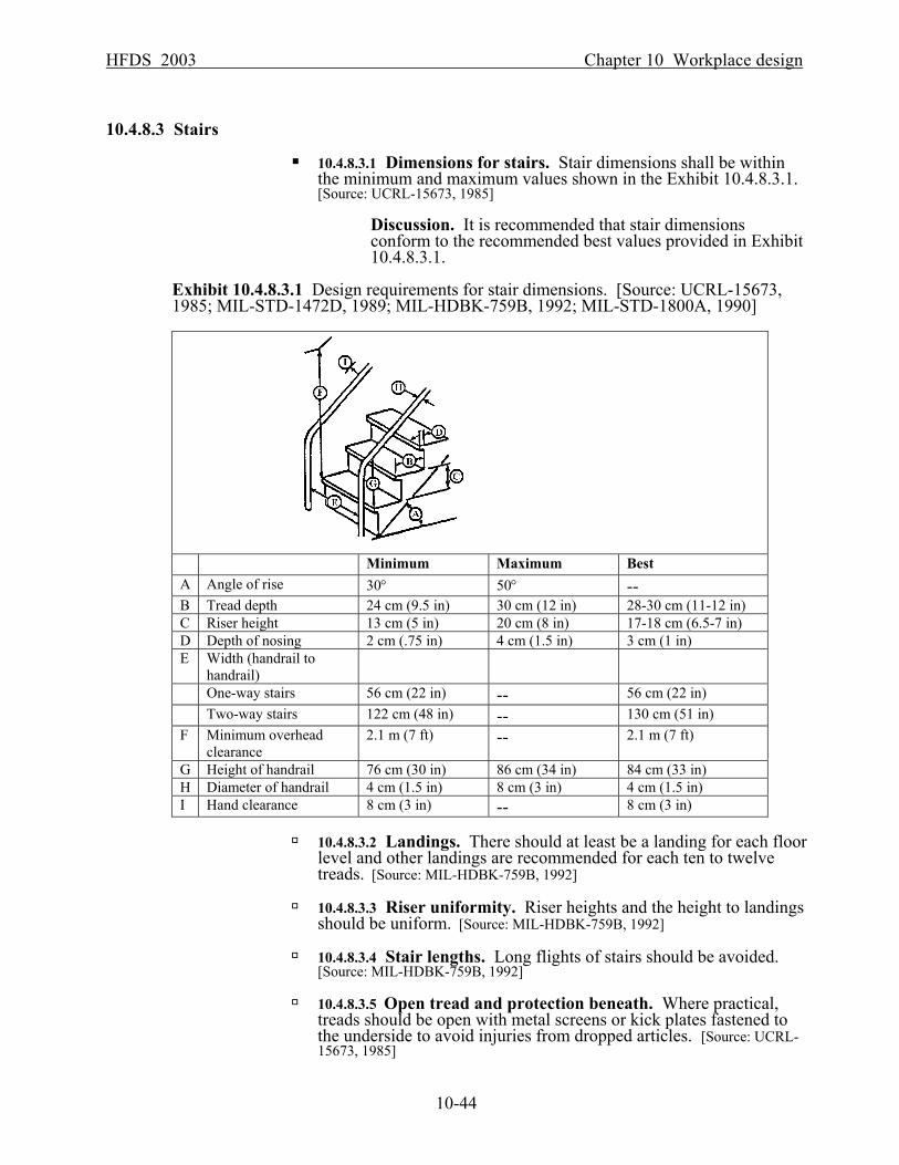
HFDS 2003 Chapter 10 Workplace design
10.4.8.3 Stairs
10.4.8.3.1 Dimensions for stairs. Stair dimensions shall be within
the minimum and maximum values shown in the Exhibit 10.4.8.3.1. [Source: UCRL-15673, 1985]
Discussion. It is recommended that stair dimensions conform to the recommended best values provided in Exhibit 10.4.8.3.1.
Exhibit 10.4.8.3.1 Design requirements for stair dimensions. [Source: UCRL-15673, 1985; MIL-STD-1472D, 1989; MIL-HDBK-759B, 1992; MIL-STD-1800A, 1990]
Minimum Maximum Best A Angle of rise 30° 50° -- B Tread depth 24 cm (9.5 in) 30 cm (12 in) 28-30 cm (11-12 in) C Riser height 13 cm (5 in) 20 cm (8 in) 17-18 cm (6.5-7 in) D Depth of nosing 2 cm (.75 in) 4 cm (1.5 in) 3 cm (1 in) E Width (handrail to
handrail)
One-way stairs 56 cm (22 in) -- 56 cm (22 in) Two-way stairs 122 cm (48 in) -- 130 cm (51 in) F Minimum overhead
clearance 2.1 m (7 ft) -- 2.1 m (7 ft)
G Height of handrail 76 cm (30 in) 86 cm (34 in) 84 cm (33 in) H Diameter of handrail 4 cm (1.5 in) 8 cm (3 in) 4 cm (1.5 in) I Hand clearance 8 cm (3 in) -- 8 cm (3 in)
10.4.8.3.2 Landings. There should at least be a landing for each floor
level and other landings are recommended for each ten to twelve treads. [Source: MIL-HDBK-759B, 1992]
10.4.8.3.3 Riser uniformity. Riser heights and the height to landings should be uniform. [Source: MIL-HDBK-759B, 1992]
10.4.8.3.4 Stair lengths. Long flights of stairs should be avoided. [Source: MIL-HDBK-759B, 1992]
10.4.8.3.5 Open tread and protection beneath. Where practical, treads should be open with metal screens or kick plates fastened to the underside to avoid injuries from dropped articles. [Source: UCRL-15673, 1985]
10-44

Chapter 10 Workplace design HFDS 2003
10.4.8.3.6 Stair design for load carrying. When people are going to
carry loads of more than 9 kg (20 lb) or where stairs are more than two stories high, deep treads, 300 mm (12 in), and low risers 125 mm (5 in) should be used. [Source: UCRL-15673, 1985]
Note. The following criteria are suggested by Building Officials and Code Administrators (BOCA): minimum tread depth, 280 mm (11 in); minimum riser height, 100 mm (4 in); and maximum riser height, 180 mm (7 in). OSHA 29 CFR 1910.23 (e)(6) requires a minimum hand clearance of 75 mm (3 in). Stair railings (hand railings) are a minimum of 76 cm (30 in) and a maximum of 86 cm (34 in) above the leading edge of step treads. OSHA 29 CFR 1910.24 (d) requires that a fixed stairs be a minimum stair rail (handrail) to stair rail distance of 56 cm (22 in) and have a minimum overhead clearance of 2.1 m (7 ft).
10-45

HFDS 2003 Chapter 10 Workplace design
10.4.8.4 Stair ladders
10.4.8.4.1 Dimensions for stair ladders. Stair ladder dimensions
shall be within the minimum and maximum best values recommended in Exhibit 10.4.8.4.1. [Source: UCRL-15673, 1985] Exhibit 10.4.8.4.1 Design requirements for stair ladders.
Note. OSHA 29 CFR 1910.28 requires a standard stair railing and not a handrail if the fall distance is greater than 1.2 m (48 in). Also, Exhibit 10.4.8.4.1 shows a drawing of open stairs where OSHA requires stairs to be closed.
10-46

Chapter 10 Workplace design HFDS 2003
10.4.8.4.2 Two way traffic with stair ladders. When simultaneous two way traffic is desired, separate up and down ladders should be provided, located side by side with double center handrails and a minimum separation of 150 mm (6 in) (200 mm (8 in preferred separation)) between these rails. [Source: UCRL-15673, 1985]
Note. Stair ladders are intended for one person at a time either coming up or down.
10.4.8.4.3 Open treads and protection. Treads should be open
(without risers boards) and have screens or kick plates fastened to the underside to prevent injury to personnel or damage to equipment if objects are dropped. [Source: UCRL-15673, 1985]
10-47

HFDS 2003 Chapter 10 Workplace design
10.4.8.5 Fixed ladders
10.4.8.5.1 Dimensions for fixed ladders. Fixed ladder dimensions
shall be within the minimum and maximum values in the Exhibit 10.4.8.5.1, preferably conforming to the recommended best values [Source: UCRL-15673, 1985]
Note. OSHA 29 CFR 1910.27 recommends a maximum rung spacing of 305 cm (12 in) and recommends a minimum clearance of back of the ladder of 18 cm (7 in). OSHA 29 CFR 1910.27 covers many more varieties and dimensions for fixed ladders.
Exhibit 10.4.8.5.1 Design requirements for fixed ladders.
Minimum Maximum Best A Angle of rise 60° 90° 75-90° B Rung or cleat diameter wood 3 cm (1.18 in) 4 cm (1.5 in) 4 cm (1.5 in) protected metal 2 cm (.75 in) 4 cm (1.5 in) 4 cm (1.5 in) metal that may rust 3 cm (1.18 in) 4 cm (1.5 in) 4 cm (1.5 in) C Rung spacing 23 cm (9 in) 30 cm (12 in) 28-30 cm (11-12 in) D Height, rung to landing 15 cm (6 in) 30 cm (12 in) 28-30 cm (11-12 in) E Width between stringers 30 cm (12 in) -- 46-53 cm (18-21 in) F Climbing clearance width 76 cm (30 in) -- -- G Minimum clearance depth in back of ladder 18 cm (7 in) -- 20 cm (8 in) on climbing side 91 cm for 76°
(36 in for 76°)
76 cm for 90° (30 in for 90°)
H Height of string above landing
-- -- 91cm (36in)
I Maximum height of climb -- 3m (10ft) 2.4m (8ft)
10.4.8.5.2 Guarded landings, entrances. When fixed ladders are used between several floors, the landings and entrances should be guarded, especially if the ladder well is open. [Source: 29 CFR 1910.27, 1985; UCRL-15673, 1985; MIL-STD-1800A, 1990]
10-48

Chapter 10 Workplace design HFDS 2003
10.4.8.5.3 Cages and safety devices. Cages or ladder safety devices
complying with Exhibit 10.4.8.5.3 should be provided for fixed ladders over 6.1 m (20 ft) long. [Source: 29 CFR 1910.27, 1985; UCRL-15673, 1985; MIL-STD-1800A, 1990] Exhibit 10.4.8.5.3 Design requirements for fixed ladder cage dimensions.
Min Max A Height of cage from 213 cm 244 cm base of ladder (84 in) (96 in) B Flare at bottom "C" + 10.1 cm of the cage ("C" + 4 in) C Depth of cage from 69 cm 71 cm center of ladder (27 in) (28 in) D Distance between - 46 cm cage ribs - (18 in) E Width of cage 69 cm 71
(27 in) (28 in)
10.4.8.5.4 Obstruction free cages. The inside of fixed ladder cages shall be free of all obstructions. [Source: 29 CFR 1910.27, 1985; UCRL-15673, 1985; MIL-STD-1800A, 1990]
10.4.8.5.5 Rungs versus level steps. Rungs provide better hand holds than steps, but when handrails are provided on both sides of the ladder, level steps 75 to 100 mm (3 - 4 in) wide should be used. [Source: UCRL-15673, 1985]
10.4.8.5.6 Nonskid surfaces on rungs. All rungs should have nonskid surfaces. [Source: UCRL-15673, 1985]
10.4.8.5.7 Tread and tread rise. Tread rise should be open in the rear. [Source: MIL-STD-1472D, 1989]
10-49

HFDS 2003 Chapter 10 Workplace design
10.4.8.5.8 Exterior stair ladders. The surface of treads on exterior stair ladders should be constructed of open grating material or be treated with nonskid material. [Source: MIL-STD-1472D, 1989]
10.4.8.6 Portable ladders 10.4.8.6.1 Dimensions for portable ladders. Portable ladder
dimensions shall be within the minimum and maximum values (preferably conform to the recommended best values) in Exhibits 10.4.8.6.1 (a) for stepladders and Exhibit 10.4.8.6.1 (b) for portable rung ladders. [Source: 29 CFR 1910.25-26, 1985; UCRL-15673, 1985; MIL-HDBK-759B, 1992]
Note. OSHA 29 CFR 1910.25-26 provides guidance for the design and use of ladders. [Source: 29 CFR 1910.25-26, 1985; UCRL-15673, 1985; MIL-HDBK-759B, 1992]
Exhibit 10.4.8.6.1 (a) Design requirements for portable step ladders.
A Spread 9 cm (3.5 in) per 30 cm (12 in) length of
front section plus 5 cm (2 in) per 30 cm (12 in) length of back section
B Tread width minimum: 8 cm (3 in)
best: 8-10 cm (3-4 in) C Step spacing wood: minimum: 23 cm (9 in) maximum: 30 cm (12 in)
metal: actual: 30 cm (12 in) D Width between wood ladders: 29 cm (11.5 in)* side rails at top step metal ladders: 30 cm (12 in)** E Width at bottom add 3 cm (1 in) per foot of length F Length of ladder maximum: 6.1 m (20 ft)
10-50

Chapter 10 Workplace design HFDS 2003
Exhibit 10.4.8.6.1 (b) Design requirements for portable rung ladders.
10.4.8.6.2 Lifting ladders. Where one person is to lift ladders and store them by hand, ladder weights shall not exceed 9.0 kg (20 lb) for a lift distance of 1.83 m (6 ft) or 11.3 kg (25 lb) for a lift distance of 1.52 m (5 ft.). [Source: UCRL-15673, 1985; MIL-HDBK-759B, 1992]
10.4.8.6.3 Ladder hinges and locks. Permanent hinges and locks should be used in preference to bolts and nuts for assembly of two-section extension ladders. [Source: UCRL-15673, 1985; MIL-HDBK-759B, 1992]
10-51

HFDS 2003 Chapter 10 Workplace design
10.4.8.6.4 Weather implications for portable ladders. Ladders
should be provided with rubber-cleated, pivoted feet for use in nonfreezing weather, and steel cleats for use in ice and snow. [Source: UCRL-15673, 1985; MIL-HDBK-759B, 1992]
Note. OSHA 29 CFR 1910.26-29 treats additional details for design and use of a variety of ladders and scaffolding.
10-52

Chapter 10 Workplace design HFDS 2003
Glossary
Corridors - Walkways that are physically restricted by walls or the like. Limit stops - mechanical mechanisms designed to restrict a moving object or part by stopping it at predetermined (limit) positions. N - A metric term for the force measure called a Newton. Newton - A one pound force in the English measurement system is equal to 4.4482 Newton (1 lbf = 4.4482 N). Passageways - Areas across which people must pass for work purposes. Public entrances - any entrances that are not loading or service entrances. Walkways - Areas designated for walking. Workplaces - An area room or establishment where work is done. Workstations - A place designed for a specific task or activity from where work is conducted or operations are directed. Desks, offices, repair benches, tools, equipment, and computer terminals are examples of these special accommodations and equipment. Workstations are designed as areas for one or more workers to use in accomplishing purposeful tasks or jobs.
10-53

HFDS 2003 Chapter 10 Workplace design
References Department of Defense. (1989). Human engineering design criteria for military systems,
equipment and facilities (MIL-STD-1472D). Philadelphia, PA: Navy Publishing and Printing Office.
Department of Defense. (1990). Human engineering performance requirements for systems (MIL-
STD-1800A). Philadelphia, PA: Navy Publishing and Printing Office. Department of Defense. (1992). Human factors engineering design for Army materiel (MIL-
HDBK-759B). Philadelphia, PA: Navy Publishing and Printing Office. Department of Defense. (1998). Aircraft application of nonslip walkway, coating and matting
(MIL-W-5050). Philadelphia, PA: Navy Publishing and Printing Office. Department of Defense. (1998). Nonslip walkway compound and nonslip walkway matting (MIL-
W-5044). Philadelphia, PA: Navy Publishing and Printing Office. Department of Energy. (1985). Human factors design guidelines for maintainability of Department
of Energy nuclear facilities (UCRL-15673). Washington, DC: United States Department of Energy.
Department of the Air Force. (1980). Human factors engineering (AFSC DH 1-3). Wright-
Patterson AFB, OH: ASD/ENESS. Electric Power Research Institute. (1984). Human factors guide for nuclear power plant control
room development (EPRI NP-36591). Palo Alto, CA: Research Reports Center. National Aeronautics and Space Administration. (1989). Man-systems integration standards
(NASA-STD-3000A). Houston, TX: National Aeronautics and Space Administration. Title 29. Occupational health and safety standards (OSHA 29 C.F.R.). Rehabilitation Act of 1973,
29 U.S.C. § 794 et seq. (amended 1974). Part 1910. Occupational Health and Safety Standards (29 CFR 1910). Washington, DC.
Uniform Federal Accessibility Standard (UFAS). (1988). 41 CFR Ch101 subpart 101-19.6
Appendix A. Available online from www.access-board.gov VanCott, H. P., & Kinkade, R.G. (1972). Human engineering guide to equipment design.
Washington, DC: United States Government Printing Office.
10-54

Chapter 10 Workplace design HFDS 2002
Index
F A Floor space ............................................ 10-23 Access ....................................................10-37 Floors..........................................10-27, 10-29 Access openings.....................................10-25 Folding doors......................................... 10-35 Access space ..........................................10-24 Footrests .................................................. 10-9 Accessible route Furniture clearances .............................. 10-34 slope ...................................................10-29
Armrests...................................................10-8 G
C Glass doors ............................................ 10-35 Ground and floor surfaces ..................... 10-29 Cages......................................................10-49 Guard screen.......................................... 10-32 Caster rollers ............................................10-6 Guardrails ....................... 10-30, 10-31, 10-40 Catwalks.................................................10-30
Ceiling areas...........................................10-36 H Clearance dimensions ..............................10-1
Component locations .............................10-25 Handholds...................................10-31, 10-32 Connecting entrances .............................10-28 Handrails ............................................... 10-40 Connecting routes ..................................10-28 Hatches .................................................. 10-36 Console design .........................................10-2 Console dimensions .................................10-3 I Corridors ................................................10-26
Illumination ..................................10-2, 10-41 Crawl spaces ..........................................10-30 Inclinators .............................................. 10-30
D K
Door clearances......................................10-34 Kickspace .............................................. 10-19 Door opening .........................................10-34 Knee space height.................................... 10-8 Doorways and hinged doors...................10-34 Kneeling ................................................ 10-21
E L
Elevators ................................................10-30 Ladders .................................................. 10-39 Elevators, inclinators, and hydraulic work
platforms ............................................10-33 fixed ladders ...................................... 10-48 portable ladders ................................. 10-50 Emergency door design..........................10-36 stair ladders........................................ 10-46 Emergency escape hatches.....................10-38
Landings .....................................10-30, 10-44 Emergency exits.....................................10-35 Lateral work space................................. 10-24 Entrances and exits ................................10-33 Lifting ladders ....................................... 10-51 doorways ............................................10-34
hatches................................................10-36 M whole body access..............................10-37 Maintenance ............................................ 10-2 Equipment clearances ............................10-34 Maintenance workstations ..................... 10-20 Equipment grouping...............................10-22 Multi-person consoles ........................... 10-12 Equipment layout ...................................10-22
Exit design .............................................10-36 Exterior platforms ..................................10-31
10-55

HFDS 2003 Chapter 10 Workplace design
N
Nonskid floor surfaces ...........................10-40 Non-skid material...................................10-31
P Passageways...........................................10-26 Physical accommodation .........................10-1 Platform strength....................................10-31 Platforms ................................................10-30 Portable platforms..................................10-31 Prone ......................................................10-21
R Ramp cleating ........................................10-43 Ramp dimensions...................................10-41 Ramp landings .......................................10-41 Ramps ........................................ 10-39, 10-42
landings ..............................................10-30 Reach limits ...........................................10-25 Rear access space...................................10-24 Redundant information ............................10-2 Repair.....................................................10-20 Rescue requirements, hatches ................10-37 Revolving doors .....................................10-35
S Screens ...................................................10-31 Seat cushioning ........................................10-8 Seated workplaces....................................10-5 Seating dimensions ..................................10-6 Sliding doors ..........................................10-35 Spacing...................................................10-23 Squatting ................................................10-21 Stacked consoles ....................................10-11 Stair design.............................................10-45 Stairs .......................................... 10-39, 10-44
Standing workstations ........................... 10-16 Stooping................................................. 10-21 Storage................................................... 10-20 Supine.................................................... 10-21 Swinging doors...................................... 10-35 Swivel capability ..................................... 10-6
T Team console types ............................... 10-15 Toe board............................................... 10-32 Toeholds ................................................ 10-31 Traffic areas........................................... 10-22 Tunnels .................................................. 10-30
U Unusual working positions.................... 10-20
V Vehicular traffic .................................... 10-42 Vertical stacked consoles ...................... 10-11 Visibility of controls................................ 10-2 Visibility of displays ............................... 10-2 Visual access ......................................... 10-26
W Walking traffic ...................................... 10-42 Walkways .............................................. 10-26 Warning labels....................................... 10-40 Wheelchair accessibility........................ 10-28 Work space to permit access ................. 10-24 Work surfaces........................................ 10-19 Workplace design .................................... 10-1
layout ................................................. 10-22 Workspace clearance dimensions.......... 10-20 Workstation ............................................. 10-1 Wrap-around console ............................ 10-10
10-56