table of contents - bweb.brp-jp.combweb.brp-jp.com/pdf/skpd2014-4 en.pdf · summit x...
TRANSCRIPT

August 23, 2013 Subject:Ski-Doo REV-XS and REV-XM PredeliveryInspection
No. 2014-4
YEAR MODEL MODEL NUMBER SERIAL NUMBER
2014 REV-XS and REV-XM Refer to table on next pages for model listing All
TABLE OF CONTENTSPage Page
IMPORTANT NOTICE ..... . . . . . . . . . . . . . . . . . . 2High altitude calibration... . . . . . . . . . . . . . . . . . . . . . 2
MODEL LISTING..... . . . . . . . . . . . . . . . . . . . . . . . . 3
PREDELIVERY KIT PARTS LIST ..... . . . . . 4
UNCRATING ...... . . . . . . . . . . . . . . . . . . . . . . . . . . . . 5Crate Cover.. . . . . . . . . . . . . . . . . . . . . . . . . . . . . . . . . . . . . 5Crate Brackets .. . . . . . . . . . . . . . . . . . . . . . . . . . . . . . . . . 5Tunnel Bag (GSX Models) . . . . . . . . . . . . . . . . . . . . . 6Snow Guard ... . . . . . . . . . . . . . . . . . . . . . . . . . . . . . . . . . . 6Rear Bumper .. . . . . . . . . . . . . . . . . . . . . . . . . . . . . . . . . . . 6Rear Suspension Shipping Hook(s) . . . . . . . . . . 6
PARTS TO BE INSTALLED...... . . . . . . . . . . . 7Front Shock Absorbers ... . . . . . . . . . . . . . . . . . . . . . 7Skis .. . . . . . . . . . . . . . . . . . . . . . . . . . . . . . . . . . . . . . . . . . . . . . 9Battery ... . . . . . . . . . . . . . . . . . . . . . . . . . . . . . . . . . . . . . . . . 10Handlebar ... . . . . . . . . . . . . . . . . . . . . . . . . . . . . . . . . . . . . . 11Steering Cover .. . . . . . . . . . . . . . . . . . . . . . . . . . . . . . . . . 12Tools and Emergency Starting Rope... . . . . . . 13Handlebar Wind Deflector (ApplicableModels) .. . . . . . . . . . . . . . . . . . . . . . . . . . . . . . . . . . . . . . . . . 13Mountain Strap (Renegade Backcountry,Summit and Freeride Models) . . . . . . . . . . . . . . . . 14Heated Visor Extension (Expedition and GSXModels) .. . . . . . . . . . . . . . . . . . . . . . . . . . . . . . . . . . . . . . . . . 14Drive Belt Installation .. . . . . . . . . . . . . . . . . . . . . . . . . 14Hitch (Expedition Sport) . . . . . . . . . . . . . . . . . . . . . . . 16Side Reflectors.. . . . . . . . . . . . . . . . . . . . . . . . . . . . . . . . . 16Front Reflector (European Models) . . . . . . . . . . 16
FLUIDS...... . . . . . . . . . . . . . . . . . . . . . . . . . . . . . . . . . . . 18General Guidelines ... . . . . . . . . . . . . . . . . . . . . . . . . . . 18
Fuel .. . . . . . . . . . . . . . . . . . . . . . . . . . . . . . . . . . . . . . . . . . . . . . 18Engine Coolant... . . . . . . . . . . . . . . . . . . . . . . . . . . . . . . . 19Chaincase Oil. . . . . . . . . . . . . . . . . . . . . . . . . . . . . . . . . . . . 19Injection Oil. . . . . . . . . . . . . . . . . . . . . . . . . . . . . . . . . . . . . . 19Brake Fluid Level .. . . . . . . . . . . . . . . . . . . . . . . . . . . . . . 20Engine Oil (900 ACE).. . . . . . . . . . . . . . . . . . . . . . . . . . 20
UPPER BODY MODULE INSTALLA-TION...... . . . . . . . . . . . . . . . . . . . . . . . . . . . . . . . . . . . . . . 21
Front Storage Compartment Cover ... . . . . . . . 21Console Wind Deflectors (if Equipped) .. . . . . 22Windshield.. . . . . . . . . . . . . . . . . . . . . . . . . . . . . . . . . . . . . . 22Mirrors (GSX Models) . . . . . . . . . . . . . . . . . . . . . . . . . . 22
SET-UP..... . . . . . . . . . . . . . . . . . . . . . . . . . . . . . . . . . . . . 22Programming Using B.U.D.S. .. . . . . . . . . . . . . . . . 22Track.. . . . . . . . . . . . . . . . . . . . . . . . . . . . . . . . . . . . . . . . . . . . . 24
ADJUSTMENTS (CUSTOMERPREFERENCE) ..... . . . . . . . . . . . . . . . . . . . . . . . . . . . 26
Rear Suspension Adjustments ... . . . . . . . . . . . . 26
FINAL INSPECTION ...... . . . . . . . . . . . . . . . . . . . 26Controls, Equipments, Movement andOperation Inspection.. . . . . . . . . . . . . . . . . . . . . . . . . . 26Test Run Snowmobile .. . . . . . . . . . . . . . . . . . . . . . . . 26Snowmobile Cleaned and in ShowroomCondition.. . . . . . . . . . . . . . . . . . . . . . . . . . . . . . . . . . . . . . . . 26Vehicle Delivery .. . . . . . . . . . . . . . . . . . . . . . . . . . . . . . . . 27
SPECIFICATIONS ...... . . . . . . . . . . . . . . . . . . . . . . 28
Printed in Canada. (mbl2014-002 en JT)©2013 Bombardier Recreational Products Inc. and BRP US Inc. All rights reserved.
1 / 41®™ and the BRP logo are trademarks of Bombardier Recreational Products Inc. or its affiliates.

IMPORTANT NOTICE
IMPORTANT NOTICEThis bulletin must be used in conjunction with check list enclosed in bag with OPERATOR’S GUIDE. Makesure that PREDELIVERY CHECK LIST is completed and signed.
WARNING
To obtain limited warranty coverage, predelivery procedures must be performed by an autho-rized BRP Ski-Doo snowmobile dealer/distributor. Apply all necessary torques as indicated.
NOTE: The information and components/system descriptions contained in this document are correctat time of publication. Bombardier Recreational Products Inc. (BRP) however, maintains a policy ofcontinuous improvement of its products without imposing upon itself any obligation to install them onproducts previously manufactured.Due to late changes, there might be some differences between manufactured product and descriptionsand/or specifications in this document. BRP reserves the right at any time to discontinue or changespecifications, designs, features, models or equipment without incurring obligation.The illustrations in this document show typical construction of different assemblies and may notreproduce full detail or exact shape of parts. However, they represent parts that have same or similarfunction.Content of this bulletin is designed as a guideline only. All mechanics performing predelivery proceduresshould have attended current model year service training.Further information or inquiries should be directed to your distributor service representative and/orspecific SHOP MANUAL sections.Please complete PREDELIVERY CHECK LIST for each snowmobile and retain a customer signed copy.Make sure customer receives OPERATOR’S GUIDE, PREDELIVERY CHECK LIST signed copy andSAFETY DVD VIDEOIMPORTANT: Complete any applicable recall or factory directed modification.There is a tag attached to ignition key, only customer must remove it. This label will remind cus-tomer to ask dealer/distributor to perform suspension adjustments according to riding style andvehicle load.
WARNING
Torque wrench tightening specifications must strictly be adhered to. Where specified, install newlocking devices (e.g. lock tabs, elastic stop nuts). If the efficiency of a locking device is impaired,it must be renewed.
High altitude calibrationNOTE:
– Summit North American models are factory calibrated to be ridden at altitudes ranging from600 m to 2 400 m (2,000 ft to 8,000 ft).
– European Summit models and all other models are factory calibrated for sea level riding unless themodel is specifically stated as a High altitude model.
– If not re-calibrated for proper altitude use, severe engine damage may occur.– ALWAYS refer to model year HIGH ALTITUDE SERVICE BULLETIN.
2 / 41 2014-4 PREDELIVERY

MODEL LISTING
MODEL LISTINGMODEL COUNTRY ENGINE MODEL NUMBER PDI KIT P/N
CAN/US 600HO E-TEC UEEA
CAN/US 800R E-TEC UDEAMX Z TNT
CAN/US 900 ACE MAEA
CAN/US 600HO E-TEC UVEA / UVEB / UVEC / UVEDMX Z X
CAN/US 800R E-TEC UTEA / UTEB / UTEC / UTED
CAN/US 600HO E-TEC BXEA
CAN/US 800R E-TEC UFEA
CAN/US MBEARenegadeAdrenaline
EUR900 ACE
MBEB
CAN/US 600HO E-TEC UAEA / UAEB / UAEC / UAEDRenegade X
CAN/US 800R E-TEC UWEA / UWEB / UWEC / UWED
CAN/US 600HO E-TEC UJEARenegadeBackcountry CAN/US 800R E-TEC UGEA / UGEB
CAN/US ULEA / ULEB
EUR600HO E-TEC
ULEC
CAN/US UXEA / UXEB / UXEC / UXED / UXEE / UXEF/ UXEG / UXEH
RenegadeBackcountryX
EUR800R E-TEC
UXEJ
CAN/US VAEA / VAEB / VAED / VAEE / VBEA / VBEB /VCEA / VCEBFreeride
EUR800R E-TEC
VAEC / VBEC / VCEC
549 011 443
CAN/US 600HO E-TEC DDEAGSX
CAN/US 900 ACE DREA549 011 442
CAN/US KDEAExpeditionSport EUR
900 ACEKDEB
549 011 445
CAN/USTREA / TREB / TREC / TRED / TREF / TREG /TCEA / TCEB / TCEC/ TCED / TCEF / TCEG /TNEA / TNEB / TNEC / TNED / TNEF / TNEGSummit X
EUR
800R E-TEC
TREE / TCEE / TCEH / TNEE / TNEH
CAN/US CXEA / CXEB / CXEC / CXED / CCEA / CCEB/ CCEC / CCED /
EUR600HO E-TEC
CXEE / CCEE
CAN/US CDEA / CDEB / CDEC / CDED / CEEA / CEEB/ CEEC / CEED / CFEA / CFEB / CFEC / CFED
Summit SP
EUR800R E-TEC
CEEE / CFEE
549 011 443
PREDELIVERY 2014-4 3 / 41

PREDELIVERY KIT PARTS LIST
PREDELIVERY KIT PARTSLIST
KIT 549 011 442
Where used Description Part number Qty
Rear Suspension Wheel Cap 503 192 771 2
M10 Washer 503 192 496 2
M10 nuts 233 201 464 6Front suspension and skis
Ski stopper 505 072 594 2
Rear bumper M6 X 18 Torx screw 250 000 402 4
3/16 pop rivet 293 150 108 4Snow guard
Washer 517 124 300 4
Steering K50 screws 250 000 400 8
Accessories Heated visor wire 515 175 851 1
KIT 549 011 443
Where used Description Part number Qty
Rear Suspension Wheel Cap 503 192 771 2
M10 Washer 503 192 496 2
M10 nuts 233 201 464 6Front suspension and skis
Ski stopper 505 072 594 2
Washer 224 061 201 6Rear bumper
M6 X 18 Torx screw 250 000 402 6
3/16 pop rivet 293 150 108 4Snow guard
Washer 517 124 300 4
KIT 549 011 445
Where used Description Part number Qty
Rear Suspension Wheel Cap 503 192 771 2
M10 Washer 503 192 496 2
M10 flanged nut 233 201 464 6Front suspension and skis
Ski stopper 505 072 594 2
M6 X 18 Torx screw 250 000 402 6Rear bumper
Washer 224 061 201 2
Accessories Heated visor wire 515 175 851 1
Washer 224 061 201 2
M6 X 16 screw 207 361 644 2Passenger seat
M6 X 30 screw 207 563 044 2
3/16 pop rivet 293 150 101 4Snow Guard
Washer 517 124 300 4
Additional provided hardware:– Black hardware for ski and front shock absorbers (should be used to enhance the look of this model).
4 / 41 2014-4 PREDELIVERY
UNCRATING
UNCRATINGCrate Cover1. Carefully lay crate on its bottom.
NOTICE Allowing crate to drop may cause se-rious damage to vehicle.
2. Using a drill or a screwdriver, remove all screwsretaining crate cover to crate base.
NOTE: Screws that are used are Robertson† #2type that require the use of an appropriate screw-driver.3. Tilt crate cover toward front or rear of vehicle.NOTE: There is a notch at one end of crate thatindicates front of vehicle.
��
��������
1. Screwdriver2. Notch (indicates front of vehicle)3. Tilt crate cover
4. Lift crate cover slowly to avoid damaging vehi-cle.
5. Remove polyethylene foam sheets.
NOTICE Do not remove protective wrappinguntil delivery to customer.
6. Remove parts to be installed from vehicle orcrate base.
Crate Brackets
CAUTION Make sure vehicle is properlysupported before removing ski legs and rearsuspension from crate brackets.1. Cut locking ties and remove ski leg wood pro-
tectors (if applicable).2. Detach ski legs from crate shipping brackets.
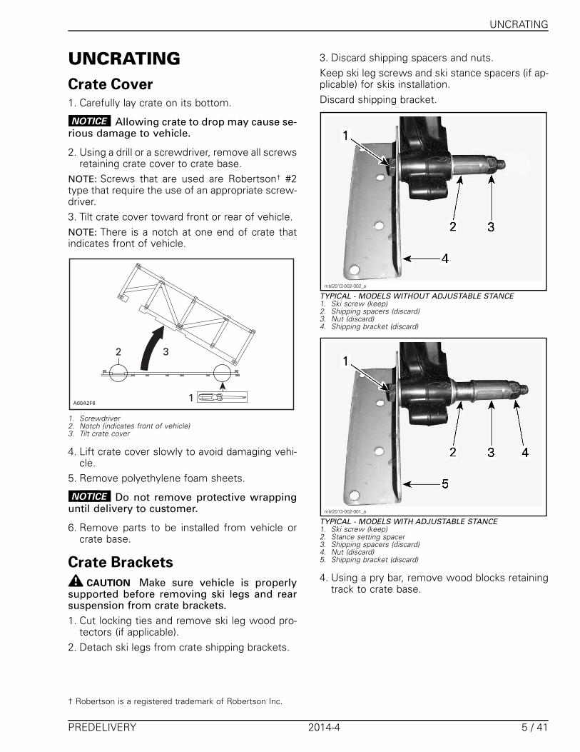
3. Discard shipping spacers and nuts.Keep ski leg screws and ski stance spacers (if ap-plicable) for skis installation.Discard shipping bracket.
mbl2013-002-002_a
TYPICAL - MODELS WITHOUT ADJUSTABLE STANCE1. Ski screw (keep)2. Shipping spacers (discard)3. Nut (discard)4. Shipping bracket (discard)
mbl2013-002-001_a
TYPICAL - MODELS WITH ADJUSTABLE STANCE1. Ski screw (keep)2. Stance setting spacer3. Shipping spacers (discard)4. Nut (discard)5. Shipping bracket (discard)
4. Using a pry bar, remove wood blocks retainingtrack to crate base.
† Robertson is a registered trademark of Robertson Inc.
PREDELIVERY 2014-4 5 / 41

UNCRATING
mbl2010-003-001_a
1. Track2. Wood block
5. Remove vehicle from crate base.
Tunnel Bag (GSX Models)GSX ModelHook the straps plastic ends to the anchors andadjust the straps.
msi2009-005-004
1. Strap2. Anchor
Snow GuardFrom underneath the rear portion of tunnel, re-move screws securing tail light.Secure the snow guard using the 3/16 pop rivetsand washers (predelivery kit).Reinstall previously removed screws.
TIGHTENING TORQUE
Tail light retaining screws 0.4 N•m (4 lbf•in)
Rear Bumper1. Align holes of rear bumper with frame holes.2. Secure rear bumper to frame using M6 x 18
Torx screws and washers (predelivery kit).
TIGHTENING TORQUE
Rear bumper screws 16 N•m (142 lbf•in)
Rear Suspension ShippingHook(s)
NOTICE Rear bumper must be installed be-fore removing the shipping hooks.
WARNING
Shipping hooks must be removed to havesnowmobile suspension operational.
WARNING
Before removing hooks, always verify thatvehicle is properly supported and that park-ing brake is applied.
1. Apply parking brake.2. Lift rear of vehicle so that a block or a box can
be positioned under front idler wheels.3. Ask another person to apply pressure onto rear
suspension.4. Remove front hook(s) from suspension.
mbl2009-010-200_a
TYPICAL1. Idler wheel2. Front hook
5. Lift front of vehicle to position bumper approx-imately 1 m (39 in) above the ground.
NOTICE Never stand on the seat.
6. Apply pressure onto rear suspension and asksomeone to remove rear hook.
6 / 41 2014-4 PREDELIVERY

PARTS TO BE INSTALLED
PARTS TO BE INSTALLEDFront Shock AbsorbersAccess to Upper Front Shock AbsorberBoltsTo access the shock upper bolts, remove the up-per body module as follows:1. Remove the gauge.
mbl2012-008-001_a
Step 1: UnlockStep 2: Tilt
2. Disconnect the gauge connector.3. Disconnect the headlights connector.
mbl2012-008-002_a
1. Headlights connector
4. Open side panels.
NOTICE The removal of side panels isnot required but its a good practice toavoid scratching them during vehiclepreparation. When side panels are re-moved, make sure to place them in a safeplace.
4.1 Unhook both rubber latches.4.2 Firmly pull the upper latch upwards.
mbl2013-002-300_a
1. Side panel2. Upper latch3. Lower latch
5. Remove the drive belt guard.6. Disconnect the air intake connector tube.
mmr2008-010-004_a
Step 1: Lift tabStep 2: Twist tubeStep 3: Pull forward
7. Disconnect air temperature sensor (ATS) on topof connector tube.
mbl2012-008-003_a
1. ATS connector
8. Open RH side panel.
PREDELIVERY 2014-4 7 / 41
PARTS TO BE INSTALLED
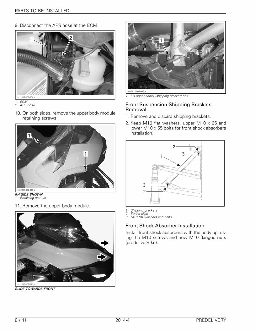
9. Disconnect the APS hose at the ECM.
mbl2012-008-004_a
1. ECM2. APS hose
10. On both sides, remove the upper body moduleretaining screws.
mbl2013-002-010_a
RH SIDE SHOWN1. Retaining screws
11. Remove the upper body module.
mbl2013-002-011_a
SLIDE TOWARDS FRONT
mbl2012-008-007_a
1. LH upper shock (shipping bracket) bolt
Front Suspension Shipping BracketsRemoval1. Remove and discard shipping brackets.2. Keep M10 flat washers, upper M10 x 65 and
lower M10 x 55 bolts for front shock absorbersinstallation.
� �
�
�
�
1. Shipping brackets2. Spring clips3. M10 flat washers and bolts
Front Shock Absorber InstallationInstall front shock absorbers with the body up, us-ing the M10 screws and new M10 flanged nuts(predelivery kit).
8 / 41 2014-4 PREDELIVERY

PARTS TO BE INSTALLED
mbl2013-002-003
TYPICAL - BODY UP
Freeride (Narrow Stance)Install the shock absorbers as per following tablein order to place the reservoirs outwards and to-wards front.
mbl2010-003-007_a
FREERIDE (NARROW STANCE)1. Reservoir (outwards and towards front)
FREERIDE (NARROW STANCE) SHOCKABSORBERS
SHOCK P/N VEHICLE SIDE
(P/N 505 073 123) LH
(P/N 505 073 124) RH
Freeride R (Wide Stance)NOTE: The wide stance Freeride model is easilyidentified by a reinforcement on the upper sus-pension arm.Install shock absorbers as per following table inorder to place the reservoirs inward and towardsfront.
mbl2011-003-200_a
SUMMIT FREERIDE (WIDE STANCE)1. Reservoir (inwards and towards front)2. Reinforcement
FREERIDE R (WIDE STANCE) SHOCKABSORBERS
SHOCK P/N VEHICLE SIDE
(P/N 505 072 938) LH
(P/N 505 072 937) RH
All Models
TIGHTENING TORQUE
Front shock absorberretaining nuts 48 N•m (35 lbf•ft)
SkisNOTE: On some models, it is possible to set skistance narrow or wide. See SKI STANCE SET-TING below.Ensure ski leg bushings are still on ski legs.1. Install ski stopper on the ski.NOTE: Position indicator at front and make surethe bump in the ski is in the groove of the ski stop-per.
mmr2008-049-028_a
TYPICAL1. Ski stopper2. Bushings
PREDELIVERY 2014-4 9 / 41

PARTS TO BE INSTALLED
2. Install ski on ski leg using the hardware asshown.
mbl2007-010-003_b
TYPICAL - EXCEPT ADJUSTABLE STANCE1. Ski stopper (predelivery kit)2. M10 x 130 bolt (previously removed)3. M10 flat washer (predelivery kit)4. M10 flanged nut (predelivery kit)5. Ski leg bushings6. Ski leg
TIGHTENING TORQUE
Ski retaining nuts 48 N•m (35 lbf•ft)
Ski Stance Setting
Renegade Backcountry X, Expedition,Freeride and Summit Models
SKI STANCE SETTING
Narrow Place spacer on the inside of ski leg
Wide Place spacer on the outside of ski leg
mbl2007-010-001_b
LH SIDE SHOWN1. Ski stopper (predelivery kit)2. M10 x 130 bolt3. M10 flat washer (predelivery kit)4. M10 flanged nut (predelivery kit)5. Ski leg bushing6. Ski leg9. Narrow adjustment10. Wide adjustment
TIGHTENING TORQUE
Ski retaining nuts 48 N•m (35 lbf•ft)
BatteryModels With Electric Starter
Battery Removal (if Shipped Installed)
WARNING
Battery BLACK ( – ) cable must always bedisconnected first and connected last. Nevercharge or boost battery while installed onvehicle.
1. Open the right side panel of the vehicle.2. Remove the battery bracket.
mbl2013-002-005_a
TYPICAL - REAR OF BATTERY1. Lower bracket screw
mbl2013-002-004_a
TYPICAL - FRONT OF BATTERY1. Upper bracket screw
3. Remove the battery.
Battery PreparationRefer to the latest edition of SKI-DOO BAT-TERIES ACTIVATION, CHARGING AND MAIN-TENANCE BULLETIN for proper activating,charging and maintenance procedure.
10 / 41 2014-4 PREDELIVERY

PARTS TO BE INSTALLED
NOTE: It is recommended to always have a fullycharged battery in the workshop, ready to be in-stalled.
Battery Installation1. Properly position the charged battery on its
rack.2. Install the bracket.3. Connect the RED ( + ) cable to the battery pos-
itive terminal.NOTE: Position the RED cable terminal vertically.
mbl2013-002-012_a
600 HO E-TEC
mbl2013-002-013_a
800R E-TEC
4. Connect BLACK ( – ) cable LAST.
WARNING
Battery BLACK ( – ) cable must always bedisconnected first and connected last. Nevercharge or boost battery while installed onvehicle.
5. Apply DIELECTRIC GREASE (P/N 293 550 004) onbattery posts and connectors.
6. Cover the RED ( + ) terminal with rubber boot.
Handlebar1. Loosen the lower steering extension retaining
screws.
mbl2012-008-012_a
1. Steering extension2. Retaining screws
2. Lift steering extension and position it as per thefollowing table.
VEHICLE ANGLE
Summit andFreeride
40°(from vertical)
MX Z, Expeditionand Renegade
20°(from vertical)
mbl2013-002-302_a
SUMMIT AND FREERIDE SERIESA. Steering extension angle
PREDELIVERY 2014-4 11 / 41
PARTS TO BE INSTALLED
mbl2013-002-301_a
MX Z, EXPEDITION AND RENEGADE SERIESA. Steering extension angle
NOTICE Make sure brake hose is routed overthe steering extension
mbl2009-010-209_c
TYPICAL - BRAKE HOSE ROUTING1. As delivered (routed below steering column)2. Correct hose routing when set up
3. Tighten steering extension lower screws tospecified torque.
TIGHTENING TORQUE
Steering extensionlower screws 24 N•m (18 lbf•ft)
4. If necessary, adjust handlebar so that brakefluid reservoir is level, tighten steering exten-sion upper screws to specified torque
TIGHTENING TORQUE
Steering extensionupper screws 24 N•m (18 lbf•ft)
NOTICE Make sure brake fluid reservoir islevel.
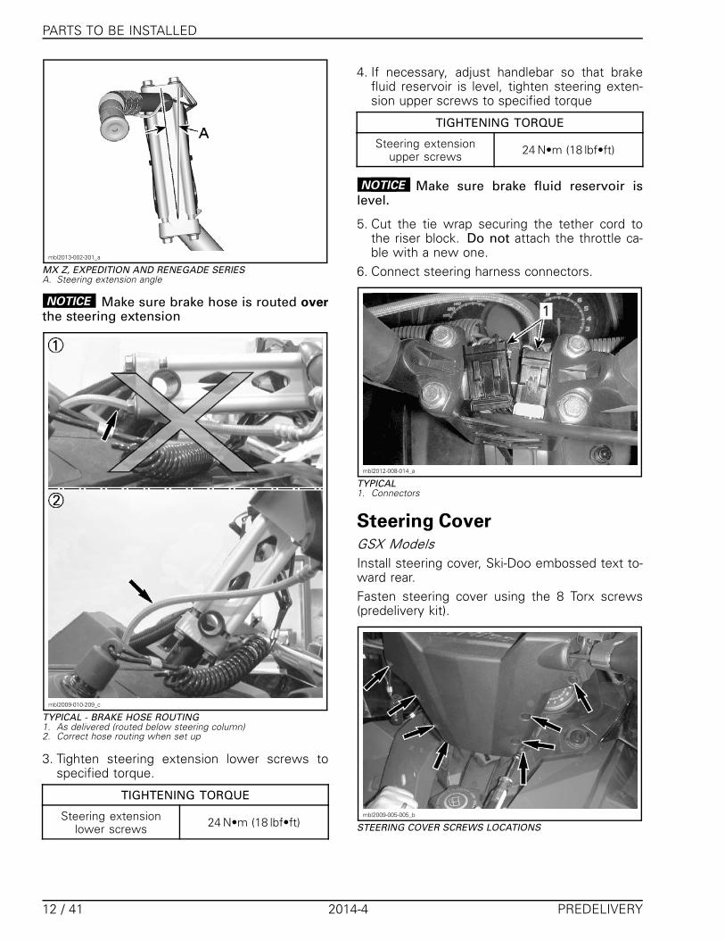
5. Cut the tie wrap securing the tether cord tothe riser block. Do not attach the throttle ca-ble with a new one.
6. Connect steering harness connectors.
mbl2012-008-014_a
TYPICAL1. Connectors
Steering CoverGSX ModelsInstall steering cover, Ski-Doo embossed text to-ward rear.Fasten steering cover using the 8 Torx screws(predelivery kit).
mbl2009-005-005_b
STEERING COVER SCREWS LOCATIONS
12 / 41 2014-4 PREDELIVERY

PARTS TO BE INSTALLED
Freeride ModelsPass the rear lower part of the cover trough theappropriate opening in the riser block.Secure cover with the snap fasteners.
mbl2012-005-005_a
TYPICAL - FRONT VIEW1. Lower part trough the riser block2. Snap fasteners
All Models Except GSX and FreerideInstall steering cover by pushing it in place.Route throttle cable and wiring properly.
mbl2013-002-006_a
1. Steering cover2. Throttle cable3. RH wiring
Tools and Emergency StartingRopeSecure the tools on the drive belt guard.
mbl2012-008-015
TOOL KIT
mbl2012-008-011
TOOLS STOWED
Stow the emergency starting rope in the openingon the LH of bottom pan.
mbl2012-008-016_a
1. Emergency starting rope2. Opening
Handlebar Wind Deflector(Applicable Models)On each side:1. Insert a M6 square nut into the wind deflector
support cavity.
PREDELIVERY 2014-4 13 / 41
PARTS TO BE INSTALLED
msi2011-004-002_a
1. Wind deflector2. M6 square nut
2. Cut the handlebar wiring tie wraps.3. Push the support end downwards to clamp it on
the handlebar.4. Thread a M6 X 35 screw but do not tighten yet.
msi2011-004-003_a
1. M6 X 35 screw
5. Position the deflector so that the support leansagainst the steering cover.
6. Set the deflector 7° below horizontal.
msi2011-004-005_a
TIGHTENING TORQUE
Wind deflector screws 3.5 N•m (31 lbf•in)
7. Secure handlebar wiring with new tie-wraps.
WARNING
Turn handlebar completely from side to sidemaking sure that wind deflectors do not inter-fere with handlebar controls and accessories(throttle lever, brake lever, emergency enginestop switch, windshield, etc).
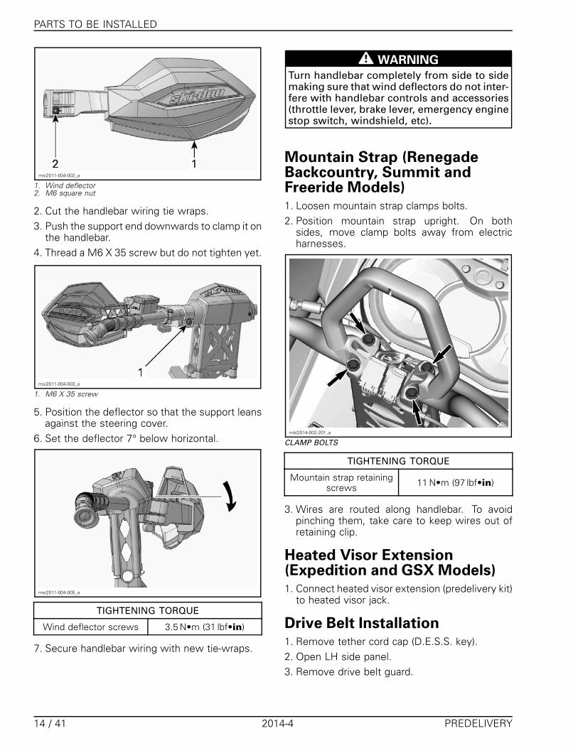
Mountain Strap (RenegadeBackcountry, Summit andFreeride Models)1. Loosen mountain strap clamps bolts.2. Position mountain strap upright. On both
sides, move clamp bolts away from electricharnesses.
mbl2014-002-201_a
CLAMP BOLTS
TIGHTENING TORQUE
Mountain strap retainingscrews 11 N•m (97 lbf•in)
3. Wires are routed along handlebar. To avoidpinching them, take care to keep wires out ofretaining clip.
Heated Visor Extension(Expedition and GSX Models)1. Connect heated visor extension (predelivery kit)
to heated visor jack.
Drive Belt Installation1. Remove tether cord cap (D.E.S.S. key).2. Open LH side panel.3. Remove drive belt guard.
14 / 41 2014-4 PREDELIVERY
PARTS TO BE INSTALLED
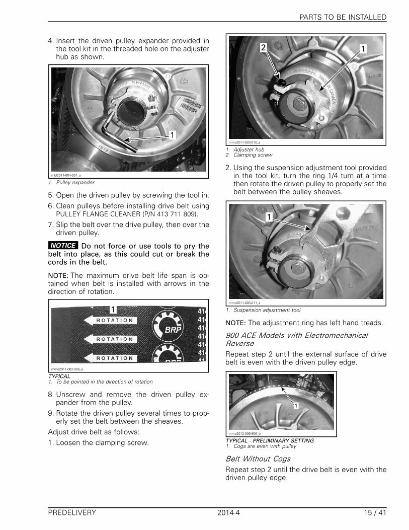
4. Insert the driven pulley expander provided inthe tool kit in the threaded hole on the adjusterhub as shown.
mbl2011-004-001_a
1. Pulley expander
5. Open the driven pulley by screwing the tool in.6. Clean pulleys before installing drive belt using
PULLEY FLANGE CLEANER (P/N 413 711 809).7. Slip the belt over the drive pulley, then over the
driven pulley.
NOTICE Do not force or use tools to pry thebelt into place, as this could cut or break thecords in the belt.
NOTE: The maximum drive belt life span is ob-tained when belt is installed with arrows in thedirection of rotation.
mmo2011-002-006_a
TYPICAL1. To be pointed in the direction of rotation
8. Unscrew and remove the driven pulley ex-pander from the pulley.
9. Rotate the driven pulley several times to prop-erly set the belt between the sheaves.
Adjust drive belt as follows:1. Loosen the clamping screw.
mmo2011-003-010_a
1. Adjuster hub2. Clamping screw
2. Using the suspension adjustment tool providedin the tool kit, turn the ring 1/4 turn at a timethen rotate the driven pulley to properly set thebelt between the pulley sheaves.
mmo2011-003-011_a
1. Suspension adjustment tool
NOTE: The adjustment ring has left hand treads.
900 ACE Models with ElectromechanicalReverseRepeat step 2 until the external surface of drivebelt is even with the driven pulley edge.
mmo2012-006-906_b
TYPICAL - PRELIMINARY SETTING1. Cogs are even with pulley
Belt Without CogsRepeat step 2 until the drive belt is even with thedriven pulley edge.
PREDELIVERY 2014-4 15 / 41
PARTS TO BE INSTALLED
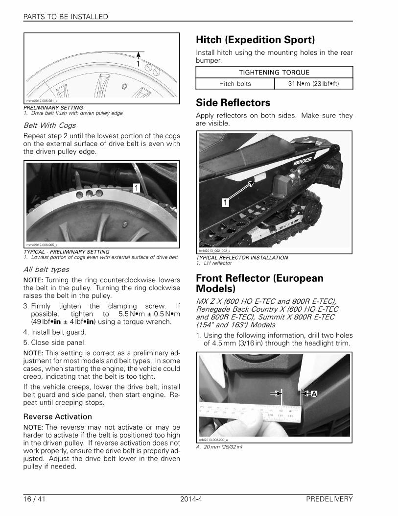
mmo2012-005-981_a
PRELIMINARY SETTING1. Drive belt flush with driven pulley edge
Belt With CogsRepeat step 2 until the lowest portion of the cogson the external surface of drive belt is even withthe driven pulley edge.
mmo2012-006-905_a
TYPICAL - PRELIMINARY SETTING1. Lowest portion of cogs even with external surface of drive belt
All belt typesNOTE: Turning the ring counterclockwise lowersthe belt in the pulley. Turning the ring clockwiseraises the belt in the pulley.3. Firmly tighten the clamping screw. If
possible, tighten to 5.5 N•m ± 0.5 N•m(49 lbf•in ± 4 lbf•in) using a torque wrench.
4. Install belt guard.5. Close side panel.NOTE: This setting is correct as a preliminary ad-justment for most models and belt types. In somecases, when starting the engine, the vehicle couldcreep, indicating that the belt is too tight.If the vehicle creeps, lower the drive belt, installbelt guard and side panel, then start engine. Re-peat until creeping stops.
Reverse ActivationNOTE: The reverse may not activate or may beharder to activate if the belt is positioned too highin the driven pulley. If reverse activation does notwork properly, ensure the drive belt is properly ad-justed. Adjust the drive belt lower in the drivenpulley if needed.
Hitch (Expedition Sport)Install hitch using the mounting holes in the rearbumper.
TIGHTENING TORQUE
Hitch bolts 31 N•m (23 lbf•ft)
Side ReflectorsApply reflectors on both sides. Make sure theyare visible.
fmbl2013_002_002_a
TYPICAL REFLECTOR INSTALLATION1. LH reflector
Front Reflector (EuropeanModels)MX Z X (600 HO E-TEC and 800R E-TEC),Renegade Back Country X (600 HO E-TECand 800R E-TEC), Summit X 800R E-TEC(154" and 163") Models1. Using the following information, drill two holes
of 4.5 mm (3/16 in) through the headlight trim.
mbl2013-002-200_a
A. 20 mm (25/32 in)
16 / 41 2014-4 PREDELIVERY

PARTS TO BE INSTALLED
mbl2013-002-201_a
A. 30 mm (1-3/16 in)
mbl2013-002-204
2. Insert locking ties in the reflector support slotsas shown.
mbl2011-003-002
3. Install the reflector support on vehicle. Makesure locking ties are installed tightly so that theydon't exceed the support recesses.
mbl2013-002-202_a
4. Clean reflector support with isopropyl alcoholand stick the reflector on the support.
mbl2013-002-203
Other Models1. Insert locking ties in the reflector support slots
as shown.
mbl2011-003-002
2. Place the reflector support centered on thefront bumper, then attach the locking ties.
PREDELIVERY 2014-4 17 / 41

FLUIDS
mbl2011-003-003
3. Install the locking ties tightly so that they don'texceed the support recesses.
mbl2011-003-004_a
LOCKING TIE INCORRECTLY TIGHTENED
mbl2011-003-005
LOCKING TIE CORRECTLY TIGHTENED (NOT EXCEEDINGRECESSES)
4. Stick the reflector on the support.Make sure the support is still centered on thebumper.
FLUIDSGeneral GuidelinesAll fluids (except fuel) have already been filled atfactory, it is only necessary to check the levels.However, if refill is needed, refer to the appropri-ate Ski-Doo SHOP MANUAL for the proper proce-dure.
FuelRecommended FuelUse unleaded gasoline containing MAXIMUM10% ethanol. The gasoline must have the follow-ing minimum octane requirements.
FUELTYPE
ENGINEMIN. OCTANE
RATING
900 ACE87 AKI
(RON+MON)/292 RONFuel
with NOethanol 600 HO E-TEC
800R E-TEC
91 AKI(RON+MON)/2
95 RON
Fuelwhichmay
containup to10%MAX
ethanol
900 ACE600 HO E-TEC
800R E-TEC
91 AKI(RON+MON)/2
95 RON
NOTICE Never experiment with other fuels.Engine or fuel system damages may occurwith the use of an inadequate fuel.
Fuel Antifreeze AdditivesWhen using oxygenated fuel, additional gas lineantifreeze or water absorbing additives are not re-quired and should be not used.When using non-oxygenated fuel, we highlyrecommend the use of isopropyl base gas lineantifreeze in a proportion of 150 ml (5 U.S. oz) ofgas line antifreeze added to 40 L (10.6 U.S. gal.)of gas.This precaution is in order to reduce the risk offrost buildup in fuel system components whichmay lead, in certain cases, to severe damage toengine.NOTE: Use only methyl hydrate free gas line an-tifreeze.
18 / 41 2014-4 PREDELIVERY

FLUIDS
Engine Coolant1. Check coolant level at room temperature with
the cap removed.Liquid should be at cold level line (engine cold) ofcoolant tank.NOTE: When checking level at low temperature itmay be slightly lower then the mark.Add if necessary.
mbl2013-002-015_a
1. COLD LEVEL line
Chaincase Oil1. With the vehicle on a level surface, check the
oil level by removing the check plug on the leftside of chaincase. Oil level must be equal withthe lower edge.
mmo2011-003-017_a
TYPICAL - 900 ACE MODELS1. Check plug
mmr2008-047-002_a
TYPICAL - 600HO E-TEC MODELS AND 800R E-TEC1. Check plug
To add oil, remove the filler cap on chaincasecover.
mbl2009-010-204_a
TYPICAL1. Filler cap
2. Pour recommended oil in chaincase by the fillerhole until oil comes out by the check plug hole.
CHAINCASE OIL CAPACITY
600 HO ETEC and800R E-TEC Models 350 ml (12 U.S. oz)
900 ACE Models 500 ml (17 U.S. oz)
Reinstall check plug and torque to specification.
CHECK PLUG TORQUE
6 N•m (53 lbf•in)
Injection OilRecommended OilAlways maintain a sufficient amount of recom-mended injection oil in the injection oil reservoir.
WARNING
Do not overfill. Reinstall cap and fullytighten. Wipe off any oil spills. Oil is highlyflammable when heated.
PREDELIVERY 2014-4 19 / 41
FLUIDS
RECOMMENDED INJECTION OIL
ENGINES
XPSSYNTHETIC
BLEND2-STROKE OIL(P/N 293 600
100)
XPSSYNTHETIC
2-STROKE OIL(P/N 293 600
132)
600 HOE-TEC
800R E-TEC (preferred)
NOTICE The engine of this snowmobile hasbeen developed and validated using the rec-ommended BRP XPS oil. BRP strongly recom-mends the use of its recommended XPS oil atall times. Damages caused by oil which is notsuitable for the engine will not be covered bythe BRP limited warranty.
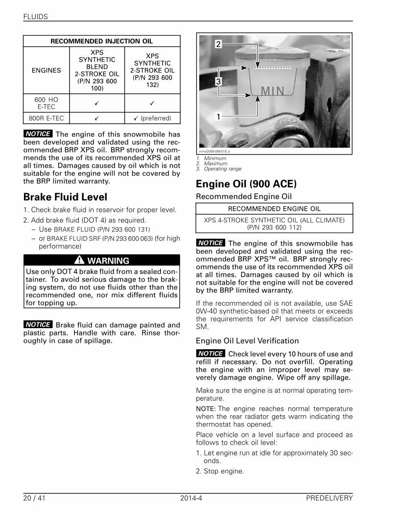
Brake Fluid Level1. Check brake fluid in reservoir for proper level.2. Add brake fluid (DOT 4) as required.
– Use BRAKE FLUID (P/N 293 600 131)– or BRAKE FLUID SRF (P/N 293 600 063) (for high
performance)
WARNING
Use only DOT 4 brake fluid from a sealed con-tainer. To avoid serious damage to the brak-ing system, do not use fluids other than therecommended one, nor mix different fluidsfor topping up.
NOTICE Brake fluid can damage painted andplastic parts. Handle with care. Rinse thor-oughly in case of spillage.
mmo2008-008-018_a
1. Minimum2. Maximum3. Operating range
Engine Oil (900 ACE)Recommended Engine Oil
RECOMMENDED ENGINE OIL
XPS 4-STROKE SYNTHETIC OIL (ALL CLIMATE)(P/N 293 600 112)
NOTICE The engine of this snowmobile hasbeen developed and validated using the rec-ommended BRP XPS™ oil. BRP strongly rec-ommends the use of its recommended XPS oilat all times. Damages caused by oil which isnot suitable for the engine will not be coveredby the BRP limited warranty.
If the recommended oil is not available, use SAE0W-40 synthetic-based oil that meets or exceedsthe requirements for API service classificationSM.
Engine Oil Level Verification
NOTICE Check level every 10 hours of use andrefill if necessary. Do not overfill. Operatingthe engine with an improper level may se-verely damage engine. Wipe off any spillage.
Make sure the engine is at normal operating tem-perature.NOTE: The engine reaches normal temperaturewhen the rear radiator gets warm indicating thethermostat has opened.Place vehicle on a level surface and proceed asfollows to check oil level:1. Let engine run at idle for approximately 30 sec-
onds.2. Stop engine.
20 / 41 2014-4 PREDELIVERY

UPPER BODY MODULE INSTALLATION
3. Open the LH side panel, refer to CONTROLS,INSTRUMENTS AND EQUIPMENT.
4. Remove the drive belt guard, refer to CON-TROLS, INSTRUMENTS AND EQUIPMENT.
5. Remove dipstick from the filler tube, then wipeit clean.
6. Completely insert dipstick in the filler tube.7. Remove dipstick and check the oil level. Oil
level should be between the MIN. and MAX.marks as shown, add if necessary.
�
��
� �
mmo2009-005-027_a
1. Oil level between MIN. and MAX.
WARNING
Wipe off any oil spills. Oil is highlyflammable when heated.
UPPER BODY MODULEINSTALLATION1. Insert the upper body module tabs into the up-
per bottom pan openings.
mbl2012-008-009_a
2. Slide the module towards rear.
mbl2013-002-011_b
3. On both sides, install the upper body moduleretaining screws.
mbl2013-002-010_a
RH SIDE SHOWN1. Retaining screws
4. Connect:– APS hose on the ECM– Headlights connector– Gauge connector– Air temperature sensor (ATS)– Air intake connector tube.
5. Install:– Gauge– Drive belt guard.
6. Install side panels
Front Storage CompartmentCoverSnap cover in place.
PREDELIVERY 2014-4 21 / 41
SET-UP
mbl2013-002-007_a
Console Wind Deflectors (ifEquipped)
mbl2013-002-014_a
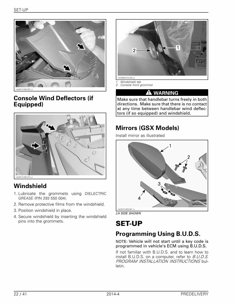
Windshield1. Lubricate the grommets using DIELECTRIC
GREASE (P/N 293 550 004).2. Remove protective films from the windshield.3. Position windshield in place.4. Secure windshield by inserting the windshield
pins into the grommets.
mbl2009-010-202_a
1. Windshield tab2. Console front grommet
WARNING
Make sure that handlebar turns freely in bothdirections. Make sure that there is no contactat any time between handlebar wind deflec-tors (if so equipped) and windshield.
Mirrors (GSX Models)Install mirror as illustrated
mbl2013-003-001_a
LH SIDE SHOWN
SET-UPProgramming Using B.U.D.S.NOTE: Vehicle will not start until a key code isprogrammed in vehicle's ECM using B.U.D.S.If not familiar with B.U.D.S. and to learn how toinstall B.U.D.S. on a computer, refer to B.U.D.S.PROGRAM INSTALLATION INSTRUCTIONS bul-letin.
22 / 41 2014-4 PREDELIVERY

SET-UP
Make sure to use the applicable version ofB.U.D.S. that can be downloaded from BOSS-Web (www.bossweb.brp.com). A valid BOSS-Web account is required.
Connecting PC to Vehicle1. Connect the PC to vehicle. Refer to the appli-
cable shop manual.
REQUIRED TOOLS
MPI-2 INTERFACECARD (P/N 529 036 018)
MPI-2 DIAGNOSTICCABLE (P/N 710 000
851)
POWER INTERFACE(P/N 515 177 223)
12 V BATTERY SUPPLYCABLE (P/N 529 035
997)
NOTE: The following message may be displayed.If so, it should disappear as soon as B.U.D.S. com-municates. If message does not disappear, clickon the Retry button.
mbl2014-006-300
2. Make sure status bar shows proper Protocol.
�������
������
CONNECTION SUCCESSFUL
NOTE: Number 2 indicates that the ECM and themultifunction gauge are recognized by the MPI.On models equipped with a THCM, a "3" will bedisplayed.
If an “X” or a “1”is shown instead of a “2” or "3",it means that there is no communication betweenMPI and ECM and/or multifunction gauge. Possi-ble causes are:– ECM and/or multifunction gauge not powered– Bad connection between MPI and ECM and/or
multifunction gauge.3. Press Read Data button to download data from
the vehicle.
vdd2006-001-101
Programing Keys with B.U.D.S.1. Install new key to be programmed on vehicle
D.E.S.S. post.2. Click on Keys tab.
smr2005-072-001_en
NOTE: When programing a vehicle for the firsttime, you need to click on Erase All Keys button.3. Click on Add Key.
smr2005-072-003_Aen
1. Add Key
4. Click on Write Data to save a new key in vehi-cle's ECM.
PREDELIVERY 2014-4 23 / 41
SET-UP
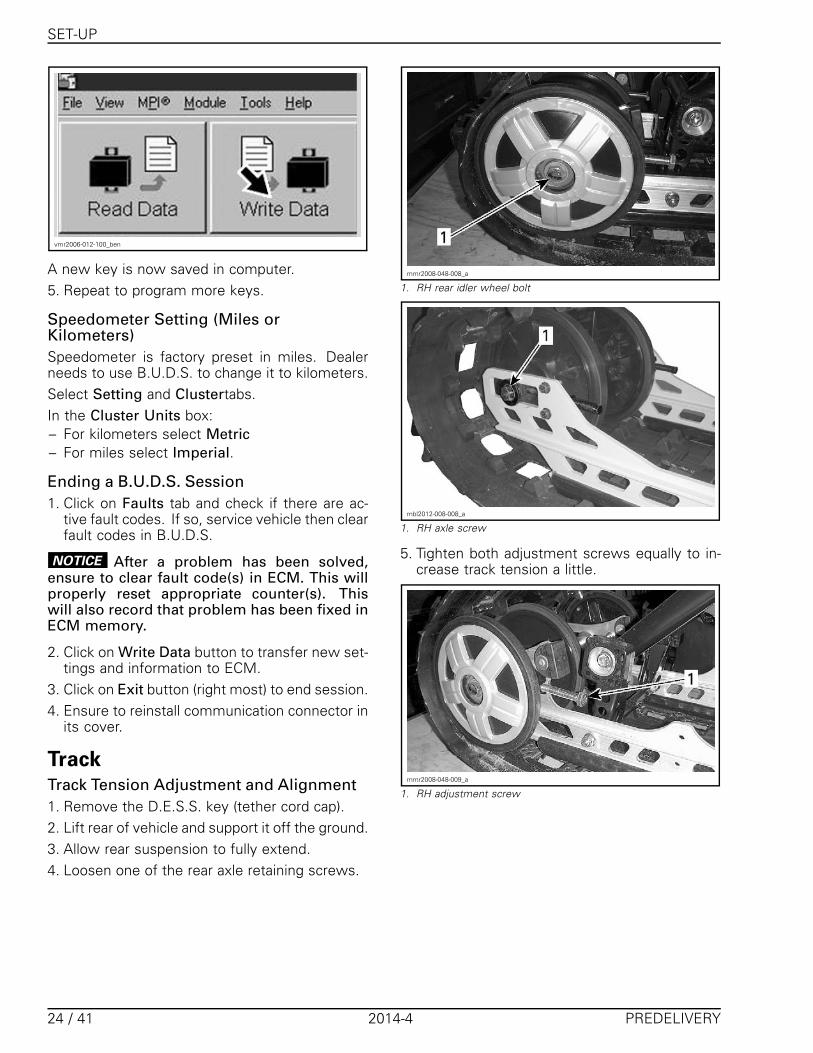
vmr2006-012-100_ben
A new key is now saved in computer.5. Repeat to program more keys.
Speedometer Setting (Miles orKilometers)Speedometer is factory preset in miles. Dealerneeds to use B.U.D.S. to change it to kilometers.Select Setting and Clustertabs.In the Cluster Units box:– For kilometers select Metric– For miles select Imperial.
Ending a B.U.D.S. Session1. Click on Faults tab and check if there are ac-
tive fault codes. If so, service vehicle then clearfault codes in B.U.D.S.
NOTICE After a problem has been solved,ensure to clear fault code(s) in ECM. This willproperly reset appropriate counter(s). Thiswill also record that problem has been fixed inECM memory.
2. Click on Write Data button to transfer new set-tings and information to ECM.
3. Click on Exit button (right most) to end session.4. Ensure to reinstall communication connector in
its cover.
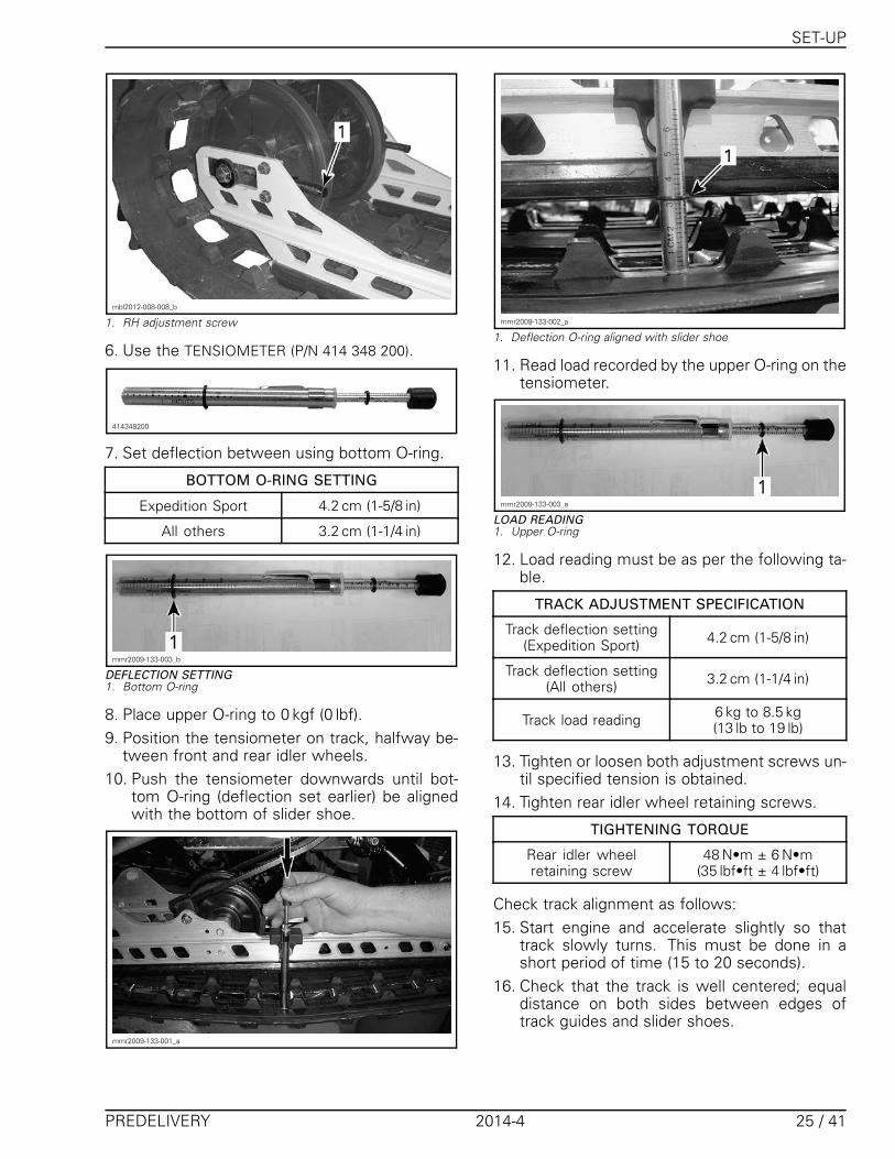
TrackTrack Tension Adjustment and Alignment1. Remove the D.E.S.S. key (tether cord cap).2. Lift rear of vehicle and support it off the ground.3. Allow rear suspension to fully extend.4. Loosen one of the rear axle retaining screws.
mmr2008-048-008_a
1. RH rear idler wheel bolt
mbl2012-008-008_a
1. RH axle screw
5. Tighten both adjustment screws equally to in-crease track tension a little.
mmr2008-048-009_a
1. RH adjustment screw
24 / 41 2014-4 PREDELIVERY
SET-UP
mbl2012-008-008_b
1. RH adjustment screw
6. Use the TENSIOMETER (P/N 414 348 200).
414348200
7. Set deflection between using bottom O-ring.
BOTTOM O-RING SETTING
Expedition Sport 4.2 cm (1-5/8 in)
All others 3.2 cm (1-1/4 in)
mmr2009-133-003_b
DEFLECTION SETTING1. Bottom O-ring
8. Place upper O-ring to 0 kgf (0 lbf).9. Position the tensiometer on track, halfway be-
tween front and rear idler wheels.10. Push the tensiometer downwards until bot-
tom O-ring (deflection set earlier) be alignedwith the bottom of slider shoe.
mmr2009-133-001_a
mmr2009-133-002_a
1. Deflection O-ring aligned with slider shoe
11. Read load recorded by the upper O-ring on thetensiometer.
mmr2009-133-003_a
LOAD READING1. Upper O-ring
12. Load reading must be as per the following ta-ble.
TRACK ADJUSTMENT SPECIFICATION
Track deflection setting(Expedition Sport) 4.2 cm (1-5/8 in)
Track deflection setting(All others) 3.2 cm (1-1/4 in)
Track load reading 6 kg to 8.5 kg(13 lb to 19 lb)
13. Tighten or loosen both adjustment screws un-til specified tension is obtained.
14. Tighten rear idler wheel retaining screws.
TIGHTENING TORQUE
Rear idler wheelretaining screw
48 N•m ± 6 N•m(35 lbf•ft ± 4 lbf•ft)
Check track alignment as follows:15. Start engine and accelerate slightly so that
track slowly turns. This must be done in ashort period of time (15 to 20 seconds).
16. Check that the track is well centered; equaldistance on both sides between edges oftrack guides and slider shoes.
PREDELIVERY 2014-4 25 / 41

FINAL INSPECTION
A01F05A
1
2
3
1. Guides2. Slider shoes3. Equal distance
17. To correct track alignment:17.1 Stop engine.17.2 Remove D.E.S.S. key (tether cord cap)17.3 Loosen one of the rear wheel retaining
screws.17.4 Tighten adjustment screw on the side
where the slider shoe is the farthestfrom the track insert guides.
18. Tighten rear idler wheel retaining screw.
TIGHTENING TORQUE
Rear idler wheelretaining screw
48 N•m ± 6 N•m(35 lbf•ft ± 4 lbf•ft)
19. Repeat procedure until alignment is correct.Recheck tension.
Track Studding
WARNING
Never stud a track that has not been ap-proved for studs. Installing studs on anunapproved track could increase risks oftrack tearing or severing, possibly resultingin serious injuries or death.
WARNING
For track studding, always refer to the IN-STRUCTION SHEET supplied with stud kitsthat are APPROVED by BRP for models cov-ered in this PREDELIVERY BULLETIN.
1. Install wheel caps (predelivery kit).NOTE: If lubricant is needed to help cap installa-tion, use glass cleaner instead of soapy water toavoid cap to get out from its location due to soapresidue.
ADJUSTMENTS(CUSTOMERPREFERENCE)Rear Suspension AdjustmentsPlease refer to OPERATOR'S GUIDE for speci-fications and procedures. You can also refer tothe SUSPENSION SPRING CHART bulletin (ifavailable).
FINAL INSPECTIONControls, Equipments,Movement and OperationInspection1. Make sure the following controls and equip-
ments are fully operational:– Throttle, brake and parking brake levers– Ignition, emergency stop switch and tether
stop switch– Headlights, taillight and brake light– Steering system.
2. Fasteners tightening torque recheck:– Ski nuts– Shock absorber nuts– Handlebar nuts.
3. Complete applicable recall or factory-directedmodification.
4. Ensure that hang tag is on vehicle handlebars.5. Ensure TOOL KIT and OPERATOR’S GUIDE are
in the vehicle.
Test Run Snowmobile1. Test ride vehicle.
Snowmobile Cleaned and inShowroom Condition1. Make sure all protective wrapping is removed
from vehicle.2. Wash and dry vehicle. Use XPS ATV WASH
(P/N 219 701 702).
NOTICE Never use a high pressure washer toclean vehicle. High pressure can cause electri-cal or mechanical damages.
For stubborn dirt on vinyl or plastic parts, usingflannel or micro-fibre towels with XPS ALL PUR-POSE CLEANER (P/N 219 701 709).
26 / 41 2014-4 PREDELIVERY
FINAL INSPECTION
NOTICE It is necessary to use flannel or micro-fiber clothes on plastic parts to avoid scratch-ing the surfaces. Never clean plastic parts withstrong detergent, paint thinner, acetone, prod-ucts containing chlorine, petroleum, etc.
Vehicle Delivery1. Complete PREDELIVERY CHECK LIST.2. Give the OPERATOR’S GUIDE and the SAFETY
DVD to the customer.3. Customer must read and sign the PREDELIV-
ERY CHECK LIST.
PREDELIVERY 2014-4 27 / 41

SPECIFICATIONS
SPECIFICATIONSThe content of SPECIFICATIONS pages should be used as necessary to fine-tune and
perform additional adjustments required on snowmobile.
600 HO E-TEC ModelsMODEL 600 HO E-TEC
ENGINEEngine type Rotax 593, liquid cooled w/Reed valve, 3D-RAVE
Cylinders 2
Displacement 594.4 cm³ (36.3 in³)
Bore 72 mm (2.8 in)
Stroke 73 mm (2.9 in)
Maximum engine speed 8100 ± 100 RPM
Fuel injection system E-TEC Direct injection
Exhaust system Single tuned pipe, baffle muffler
Engine oil XPS SYNTHETIC BLEND 2-STROKE OIL(P/N 293 600 100) (1)
Engine oil tank capacity 3.7 L (3.9 qt (U.S. liq.))
Coolant
Ethyl glycol/water mix(50% coolant, 50% distilled water).
Use LONG LIFE ANTIFREEZE (P/N 219 702 685) or coolantspecifically designed for aluminum engines
Recommended fuel Premium unleaded (fuel which may contain up to10% MAX ethanol)
91 Pump Posted AKI (RON+MON)/2Minimum octane rating. Refer to FUEL REQUIREMENTS
95 RON
Fuel tank capacity 40 L (10.6 U.S. gal.)
MODEL 600 HO E-TEC
DRIVE SYSTEMDrive pulley type TRA III
Driven pulley type QRS
All models except Summit 3400 ± 100 RPMEngagement
Summit 4000 ± 100 RPM
Chaincase oil XPS SYNTHETIC CHAINCASE OIL (P/N 413 803 300)
Summit 19
Renegade BackcountryRenegade Backcountry X 21
Renegade AdrenalineRenegade X 23
Small sprocket number of teeth
GSX LEMX Z 25
28 / 41 2014-4 PREDELIVERY
SPECIFICATIONS
MODEL 600 HO E-TEC
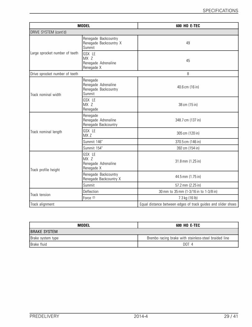
DRIVE SYSTEM (cont'd)
Renegade BackcountryRenegade Backcountry XSummit
49
Large sprocket number of teeth GSX LEMX ZRenegade AdrenalineRenegade X
45
Drive sprocket number of teeth 8
RenegadeRenegade AdrenalineRenegade BackcountrySummit
40.6 cm (16 in)
Track nominal widthGSX LEMX ZRenegade
38 cm (15 in)
RenegadeRenegade AdrenalineRenegade Backcountry
348.7 cm (137 in)
GSX LEMX Z 305 cm (120 in)
Summit 146" 370.5 cm (146 in)
Track nominal length
Summit 154" 392 cm (154 in)
GSX LEMX ZRenegade AdrenalineRenegade X
31.8 mm (1.25 in)
Renegade BackcountryRenegade Backcountry X 44.5 mm (1.75 in)
Track profile height
Summit 57.2 mm (2.25 in)
Deflection 30 mm to 35 mm (1-3/16 in to 1-3/8 in)Track tension
Force (2) 7.3 kg (16 lb)
Track alignment Equal distance between edges of track guides and slider shoes
MODEL 600 HO E-TEC
BRAKE SYSTEMBrake system type Brembo racing brake with stainless-steel braided line
Brake fluid DOT 4
PREDELIVERY 2014-4 29 / 41
SPECIFICATIONS
MODEL 600 HO E-TEC
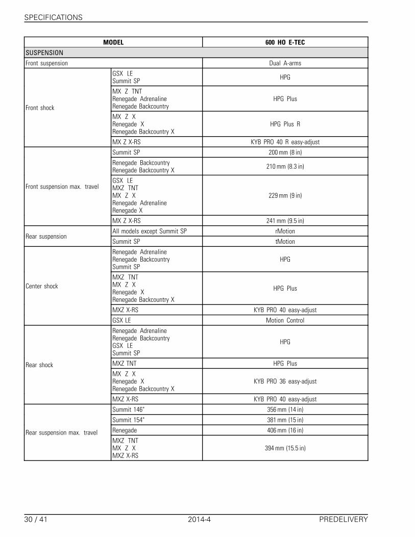
SUSPENSIONFront suspension Dual A-arms
GSX LESummit SP HPG
MX Z TNTRenegade AdrenalineRenegade Backcountry
HPG Plus
MX Z XRenegade XRenegade Backcountry X
HPG Plus R
Front shock
MX Z X-RS KYB PRO 40 R easy-adjust
Summit SP 200 mm (8 in)
Renegade BackcountryRenegade Backcountry X 210 mm (8.3 in)
GSX LEMXZ TNTMX Z XRenegade AdrenalineRenegade X
229 mm (9 in)Front suspension max. travel
MX Z X-RS 241 mm (9.5 in)
All models except Summit SP rMotionRear suspension
Summit SP tMotion
Renegade AdrenalineRenegade BackcountrySummit SP
HPG
MXZ TNTMX Z XRenegade XRenegade Backcountry X
HPG Plus
MXZ X-RS KYB PRO 40 easy-adjust
Center shock
GSX LE Motion Control
Renegade AdrenalineRenegade BackcountryGSX LESummit SP
HPG
MXZ TNT HPG Plus
MX Z XRenegade XRenegade Backcountry X
KYB PRO 36 easy-adjust
Rear shock
MXZ X-RS KYB PRO 40 easy-adjust
Summit 146" 356 mm (14 in)
Summit 154" 381 mm (15 in)
Renegade 406 mm (16 in)Rear suspension max. travelMXZ TNTMX Z XMXZ X-RS
394 mm (15.5 in)
30 / 41 2014-4 PREDELIVERY

SPECIFICATIONS
MODEL 600 HO E-TEC
ELECTRICAL SYSTEM
Lightning system output 12V/360 W55 V/1100 W
Headlights bulb HI/LOW beam 2 x 60/55 Watts (H-4)
Taillight bulb 2.6 W / 139m W LED
Type NGK PZFR6F (3)
Spark plugGap 0.75 mm ± 0.05 mm (.03 in ± .002 in)
(not adjustable)
RER 5 A
Fuel level sensor 0.25 AFuse
Main 25 A
MODEL 600 HO E-TEC
DIMENSIONS AND WEIGHTRenegade AdrenalineRenegade BackcountryRenegade Backcountry XRenegade X
311 cm (122.4 in)
GSX LEMX Z XMXZ TNTMX Z X RSRenegade X
290.5 cm (114.4 in)
Summit 146" 322.6 cm (127 in)
Vehicle overall length
Summit 154" 333.5 cm (131.3 in)
Summit SP 108.1 cm to 112.6 cm (42.6 in to 44.3 in)
Renegade BackcountryRenegade Backcountry X 115.9 cm to 120.4 cm (45.6 in to 47.4 in)
Vehicle overall widthGSX LEMX Z XMX Z X RSMXZ TNTRenegade AdrenalineRenegade X
121.7 cm (47.9 in)
GSX LEMX Z X RS 120 cm (47.2 in)
MX Z TNTMX Z XRenegade AdrenalineRenegade BackcountryRenegade X
121 cm (47.6 in)
Renegade Backcountry X 124.5 cm (49 in)
Vehicle overall height
Summit SP 134.6 cm (53 in)
PREDELIVERY 2014-4 31 / 41
SPECIFICATIONS
MODEL 600 HO E-TEC
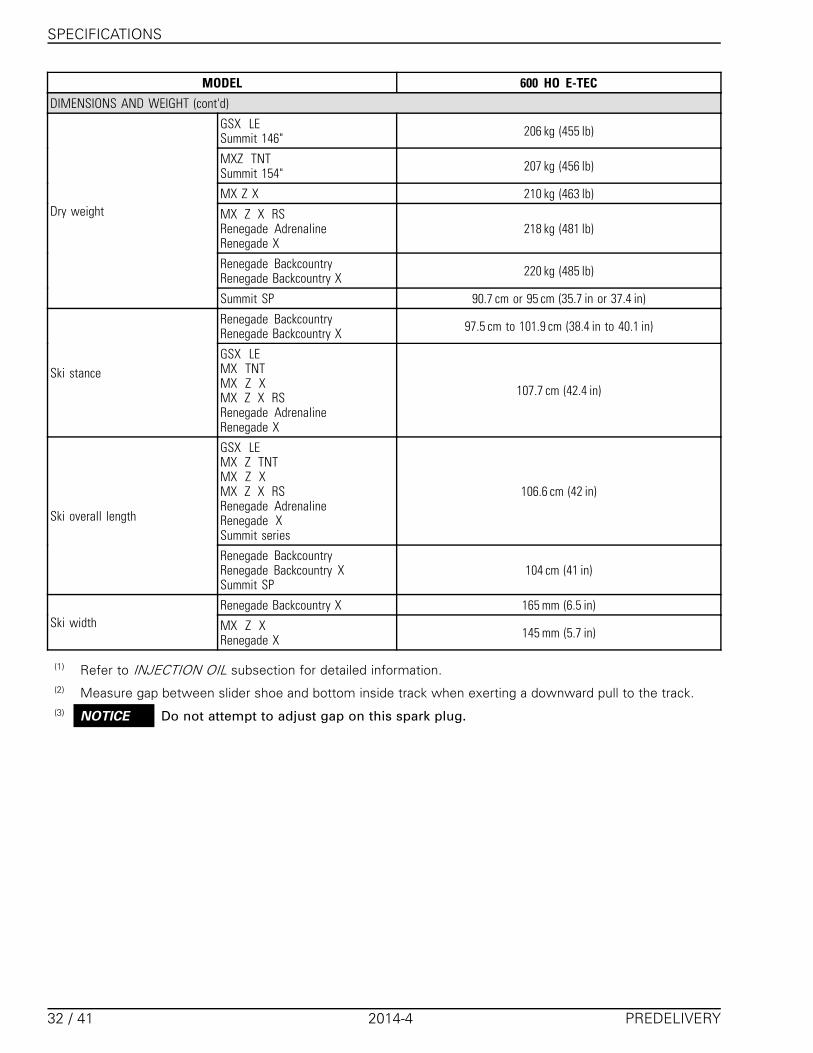
DIMENSIONS AND WEIGHT (cont'd)
GSX LESummit 146" 206 kg (455 lb)
MXZ TNTSummit 154" 207 kg (456 lb)
MX Z X 210 kg (463 lb)
MX Z X RSRenegade AdrenalineRenegade X
218 kg (481 lb)
Renegade BackcountryRenegade Backcountry X 220 kg (485 lb)
Dry weight
Summit SP 90.7 cm or 95 cm (35.7 in or 37.4 in)
Renegade BackcountryRenegade Backcountry X 97.5 cm to 101.9 cm (38.4 in to 40.1 in)
Ski stanceGSX LEMX TNTMX Z XMX Z X RSRenegade AdrenalineRenegade X
107.7 cm (42.4 in)
GSX LEMX Z TNTMX Z XMX Z X RSRenegade AdrenalineRenegade XSummit series
106.6 cm (42 in)
Ski overall length
Renegade BackcountryRenegade Backcountry XSummit SP
104 cm (41 in)
Renegade Backcountry X 165 mm (6.5 in)Ski width MX Z X
Renegade X 145 mm (5.7 in)
(1) Refer to INJECTION OIL subsection for detailed information.(2) Measure gap between slider shoe and bottom inside track when exerting a downward pull to the track.(3) NOTICE Do not attempt to adjust gap on this spark plug.
32 / 41 2014-4 PREDELIVERY
SPECIFICATIONS
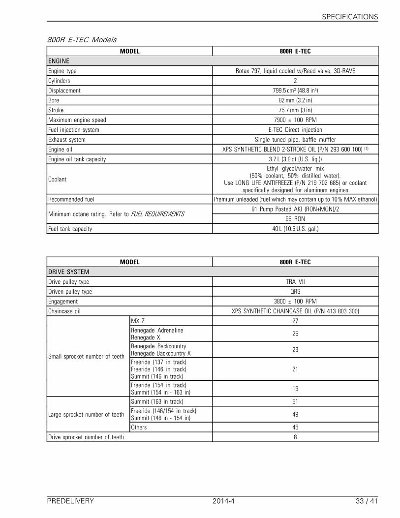
800R E-TEC ModelsMODEL 800R E-TEC
ENGINEEngine type Rotax 797, liquid cooled w/Reed valve, 3D-RAVE
Cylinders 2
Displacement 799.5 cm³ (48.8 in³)
Bore 82 mm (3.2 in)
Stroke 75.7 mm (3 in)
Maximum engine speed 7900 ± 100 RPM
Fuel injection system E-TEC Direct injection
Exhaust system Single tuned pipe, baffle muffler
Engine oil XPS SYNTHETIC BLEND 2-STROKE OIL (P/N 293 600 100) (1)
Engine oil tank capacity 3.7 L (3.9 qt (U.S. liq.))
Coolant
Ethyl glycol/water mix(50% coolant, 50% distilled water).
Use LONG LIFE ANTIFREEZE (P/N 219 702 685) or coolantspecifically designed for aluminum engines
Recommended fuel Premium unleaded (fuel which may contain up to 10% MAX ethanol)
91 Pump Posted AKI (RON+MON)/2Minimum octane rating. Refer to FUEL REQUIREMENTS
95 RON
Fuel tank capacity 40 L (10.6 U.S. gal.)
MODEL 800R E-TECDRIVE SYSTEMDrive pulley type TRA VII
Driven pulley type QRS
Engagement 3800 ± 100 RPM
Chaincase oil XPS SYNTHETIC CHAINCASE OIL (P/N 413 803 300)
MX Z 27Renegade AdrenalineRenegade X 25
Renegade BackcountryRenegade Backcountry X 23
Freeride (137 in track)Freeride (146 in track)Summit (146 in track)
21
Small sprocket number of teeth
Freeride (154 in track)Summit (154 in - 163 in) 19
Summit (163 in track) 51Freeride (146/154 in track)Summit (146 in - 154 in) 49Large sprocket number of teeth
Others 45
Drive sprocket number of teeth 8
PREDELIVERY 2014-4 33 / 41
SPECIFICATIONS
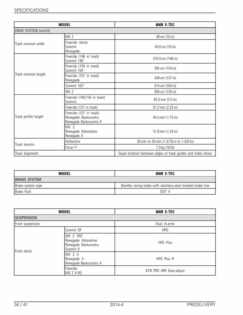
MODEL 800R E-TECDRIVE SYSTEM (cont'd)
MX Z 38 cm (15 in)
Track nominal width Freeride seriesSummitRenegade
40.6 cm (16 in)
Freeride (146 in track)Summit 146" 370.5 cm (146 in)
Freeride (154 in track)Summit 154" 392 cm (154 in)
Freeride (137 in track)Renegade 348 cm (137 in)
Summit 163" 414 cm (163 in)
Track nominal length
MX Z 305 cm (120 in)Freeride (146/154 in track)Summit 63.5 mm (2.5 in)
Freeride (137 in track) 57.2 mm (2.25 in)Freeride (137 in track)Renegade BackcountryRenegade Backcountry X
44.5 mm (1.75 in)Track profile height
MX ZRenegade AdrenalineRenegade X
31.8 mm (1.25 in)
Deflection 30 mm to 35 mm (1-3/16 in to 1-3/8 in)Track tension
Force (2) 7.3 kg (16 lb)
Track alignment Equal distance between edges of track guides and slider shoes
MODEL 800R E-TECBRAKE SYSTEMBrake system type Brembo racing brake with stainless-steel braided brake line
Brake fluid DOT 4
MODEL 800R E-TECSUSPENSIONFront suspension Dual A-arms
Summit SP HPG
MX Z TNTRenegade AdrenalineRenegade BackcountrySummit X
HPG Plus
MX Z XRenegade XRenegade Backcountry X
HPG Plus R
Front shock
FreerideMX Z X-RS KYB PRO 40R Easy-adjust
34 / 41 2014-4 PREDELIVERY

SPECIFICATIONS
MODEL 800R E-TECSUSPENSION (cont'd)
MX Z X-RS 241 mm (9.5 in)MX ZMX Z XRenegade AdrenalineRenegade X
229 mm (9 in)
FreerideRenegade BackcountryRenegade Backcountry X
210 mm (8.3 in)
Front suspension max. travel
Summit 200 mm (7.9 in)Freeride (137 in track)MX ZRenegade
rMotionRear suspension
SummitFreeride (146/154 in track) tMotion
Renegade AdrenalineRenegade BackcountrySummit SP
HPG
MX Z TNTMX Z XRenegade Backcountry XRenegade XSummit X
HPG PlusCenter shock
FreerideMX Z X-RS KYB PRO 40 Easy-adjust
Renegade AdrenalineRenegade BackcountrySummit SP
HPG
MX Z TNTSummit X HPG Plus
MX Z XRenegade Backcountry XRenegade X
KYB PRO 36 Easy-adjust
Rear shock
FreerideMX Z X-RS KYB PRO 40 Easy-adjust
Freeride (137 in track)Summit (163 in track)Renegade
40.6 cm (16 in)
MX Z 39.4 cm (15.5 in)Freeride (154 in track)Summit (154 in track) 38.1 cm (15 in)
Rear suspension max. travel
Freeride (146 in track)Summit (146 in track) 35.6 cm (14 in)
PREDELIVERY 2014-4 35 / 41

SPECIFICATIONS
MODEL 800R E-TECELECTRICAL SYSTEM
Lightning system output 12V/360 W60 V/1100 W
Headlights bulb HI/LOW beam 2 x 60/55 Watts (H-4)
Taillight bulb 2.6 W / 139m W LED
Type NGK PFR7AB (3)Spark plug
Gap 0.75 mm ± 0.05 mm (.03 in ± .002 in) (not adjustable)
RER 5 A
Fuel level sensor 0.25 AFuse
Main 25 A
MODEL 800R E-TECDIMENSIONS AND WEIGHT
MX Z 290.5 cm (114.4 in)Freeride (137 in track)Renegade 311 cm (122.4 in)
Freeride (146 in track)Summit (146 in track) 322.6 cm (127 in)
Freeride (154 in track)Summit (154 in track) 333.5 cm (131.3 in)
Vehicle overall length
Summit (163 in track) 344.5 cm (135.6 in)
Freeride series 114 cm to 118.4 cm (44.9 in to 46.6 in)MX ZRenegade AdrenalineRenegade X
121.7 cm (47.9 in)
Renegade BackcountryRenegade Backcountry X 115.9 cm to 120.4 cm (45.6 in to 47.4 in)
Vehicle overall width
Summit 108.1 cm to 112.6 cm (42.6 in to 44.3 in)
Freeride 130 cm (51.2 in)
MX Z X RS 120 cm (47.2 in)MX Z TNTMX Z XRenegade AdrenalineRenegade BackcountryRenegade X
121 cm (47.6 in)
Renegade Backcountry X 124.5 cm (49 in)
Vehicle overall height
Summit 134.6 cm (53 in)
36 / 41 2014-4 PREDELIVERY

SPECIFICATIONS
MODEL 800R E-TECDIMENSIONS AND WEIGHT
Freeride (137 in track) 219 kg (483 lb)
Freeride (146 in track) 220 kg (485 lb)Freeride (154 in track)Renegade AdrenalineRenegade X
222 kg (489 lb)
MX Z XRenegade BackcountryRenegade Backcountry X
214 kg (472 lb)
MX Z TNT 212 kg (467 lb)
Summit X (146 in track) 206 kg (454 lb)Summit X (154 in track)Summit SP (146 in track) 208 kg (459 lb)
Summit X (163 in track) 211 kg (465 lb)MX Z X RSSummit SP (154 in track) 210 kg (463 lb)
Dry weight
Summit SP (163 in track) 213 kg (470 lb)FreerideRenegade BackcountryRenegade Backcountry X
97.5 cm to 101.9 cm (38.4 in to 40.1 in)
MX ZRenegade AdrenalineRenegade X
107.7 cm (42.4 in)Ski stance
Summit 90.7 cm or 95 cm (35.7 in or 37.4 in)MX ZRenegade AdrenalineRenegade XSummit series
106.6 cm (42 in)
Ski overall lengthFreerideRenegade BackcountryRenegade Backcountry XSummit
104 cm (41 in)
Renegade Backcountry XSummit 165 mm (6.5 in)
Ski widthOthers 145 mm (5.7 in)
(1) Refer to INJECTION OIL subsection for detailed information.(2) Measure gap between slider shoe and bottom inside track when exerting a downward pull to the track.(3) NOTICE Do not attempt to adjust gap on this spark plug.
PREDELIVERY 2014-4 37 / 41
SPECIFICATIONS
900 ACE ModelsMODEL 900 ACE
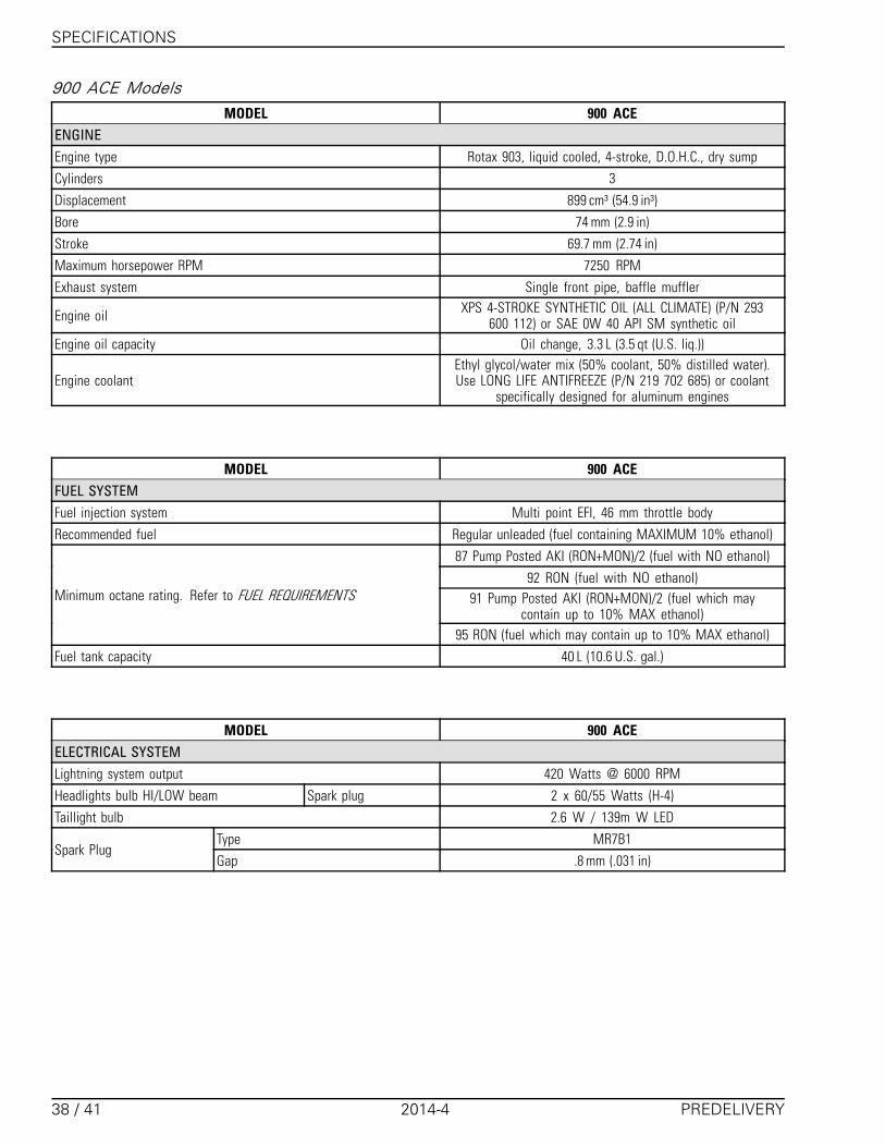
ENGINEEngine type Rotax 903, liquid cooled, 4-stroke, D.O.H.C., dry sump
Cylinders 3
Displacement 899 cm³ (54.9 in³)
Bore 74 mm (2.9 in)
Stroke 69.7 mm (2.74 in)
Maximum horsepower RPM 7250 RPM
Exhaust system Single front pipe, baffle muffler
Engine oil XPS 4-STROKE SYNTHETIC OIL (ALL CLIMATE) (P/N 293600 112) or SAE 0W 40 API SM synthetic oil
Engine oil capacity Oil change, 3.3 L (3.5 qt (U.S. liq.))
Engine coolantEthyl glycol/water mix (50% coolant, 50% distilled water).Use LONG LIFE ANTIFREEZE (P/N 219 702 685) or coolant
specifically designed for aluminum engines
MODEL 900 ACEFUEL SYSTEMFuel injection system Multi point EFI, 46 mm throttle body
Recommended fuel Regular unleaded (fuel containing MAXIMUM 10% ethanol)
87 Pump Posted AKI (RON+MON)/2 (fuel with NO ethanol)
92 RON (fuel with NO ethanol)91 Pump Posted AKI (RON+MON)/2 (fuel which may
contain up to 10% MAX ethanol)Minimum octane rating. Refer to FUEL REQUIREMENTS
95 RON (fuel which may contain up to 10% MAX ethanol)
Fuel tank capacity 40 L (10.6 U.S. gal.)
MODEL 900 ACEELECTRICAL SYSTEMLightning system output 420 Watts @ 6000 RPM
Headlights bulb HI/LOW beam Spark plug 2 x 60/55 Watts (H-4)
Taillight bulb 2.6 W / 139m W LED
Type MR7B1Spark Plug
Gap .8 mm (.031 in)
38 / 41 2014-4 PREDELIVERY
SPECIFICATIONS
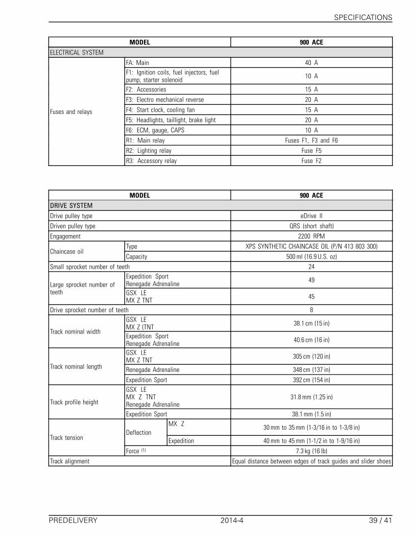
MODEL 900 ACEELECTRICAL SYSTEM
FA: Main 40 AF1: Ignition coils, fuel injectors, fuelpump, starter solenoid 10 A
F2: Accessories 15 A
F3: Electro mechanical reverse 20 A
F4: Start clock, cooling fan 15 A
F5: Headlights, taillight, brake light 20 A
F6: ECM, gauge, CAPS 10 A
R1: Main relay Fuses F1, F3 and F6
R2: Lighting relay Fuse F5
Fuses and relays
R3: Accessory relay Fuse F2
MODEL 900 ACEDRIVE SYSTEMDrive pulley type eDrive II
Driven pulley type QRS (short shaft)
Engagement 2200 RPM
Type XPS SYNTHETIC CHAINCASE OIL (P/N 413 803 300)Chaincase oil
Capacity 500 ml (16.9 U.S. oz)
Small sprocket number of teeth 24Expedition SportRenegade Adrenaline 49
Large sprocket number ofteeth GSX LE
MX Z TNT 45
Drive sprocket number of teeth 8GSX LEMX Z (TNT 38.1 cm (15 in)
Track nominal widthExpedition SportRenegade Adrenaline 40.6 cm (16 in)
GSX LEMX Z TNT 305 cm (120 in)
Renegade Adrenaline 348 cm (137 in)Track nominal length
Expedition Sport 392 cm (154 in)GSX LEMX Z TNTRenegade Adrenaline
31.8 mm (1.25 in)Track profile height
Expedition Sport 38.1 mm (1.5 in)MX Z 30 mm to 35 mm (1-3/16 in to 1-3/8 in)
DeflectionExpedition 40 mm to 45 mm (1-1/2 in to 1-9/16 in)Track tension
Force (1) 7.3 kg (16 lb)
Track alignment Equal distance between edges of track guides and slider shoes
PREDELIVERY 2014-4 39 / 41
SPECIFICATIONS
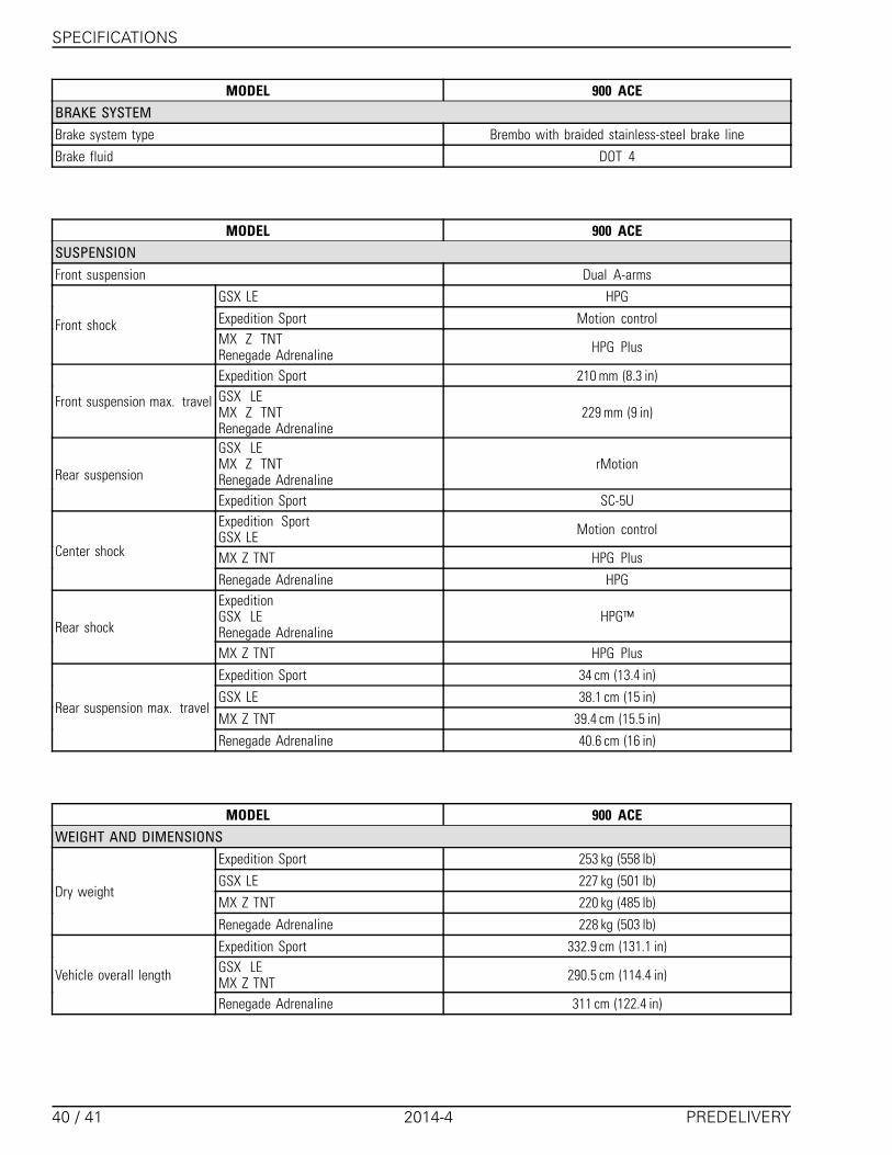
MODEL 900 ACEBRAKE SYSTEMBrake system type Brembo with braided stainless-steel brake line
Brake fluid DOT 4
MODEL 900 ACESUSPENSIONFront suspension Dual A-arms
GSX LE HPG
Expedition Sport Motion controlFront shockMX Z TNTRenegade Adrenaline HPG Plus
Expedition Sport 210 mm (8.3 in)
Front suspension max. travel GSX LEMX Z TNTRenegade Adrenaline
229 mm (9 in)
GSX LEMX Z TNTRenegade Adrenaline
rMotionRear suspension
Expedition Sport SC-5UExpedition SportGSX LE Motion control
MX Z TNT HPG PlusCenter shock
Renegade Adrenaline HPGExpeditionGSX LERenegade Adrenaline
HPG™Rear shock
MX Z TNT HPG Plus
Expedition Sport 34 cm (13.4 in)
GSX LE 38.1 cm (15 in)
MX Z TNT 39.4 cm (15.5 in)Rear suspension max. travel
Renegade Adrenaline 40.6 cm (16 in)
MODEL 900 ACEWEIGHT AND DIMENSIONS
Expedition Sport 253 kg (558 lb)
GSX LE 227 kg (501 lb)
MX Z TNT 220 kg (485 lb)Dry weight
Renegade Adrenaline 228 kg (503 lb)
Expedition Sport 332.9 cm (131.1 in)GSX LEMX Z TNT 290.5 cm (114.4 in)Vehicle overall length
Renegade Adrenaline 311 cm (122.4 in)
40 / 41 2014-4 PREDELIVERY

SPECIFICATIONS
MODEL 900 ACEWEIGHT AND DIMENSIONS (cont'd)
Expedition Sport 115.9 cm to 120.4 cm (45.6 in to 47.4 in)
Vehicle overall width GSX LEMX ZRenegade Adrenaline
121.7 cm (47.9 in)
Expedition Sport 127.5 cm (50.2 in)
GSX LE 120 cm (47.2 in)Vehicle overall heightMXZ TNTRenegade Adrenaline 121 cm (47.6 in)
Expedition Sport 97.5 cm to 101.8 cm (38.4 in to 40.1 in)
Ski stance GSX LEMX Z TNTRenegade Adrenaline
107.7 cm (42.4 in)
Expedition Sport 104 cm (41 in)
Ski overall length GSX LEMX Z TNTRenegade Adrenaline
106.6 cm (42 in)
MX ZRenegade (Can/U.S.) 145 mm (5.7 in)
Expedition 165 mm (6.5 in)Ski width
Renegade (Europe) 175 mm (6.9 in)
PREDELIVERY 2014-4 41 / 41