table of contents - uspasuspas.fnal.gov/materials/17ucdavis/vacuum/uspas 2017 vacuum ses… ·...
TRANSCRIPT

Vacuum Fundamentals
Gas Sources
Vacuum Instrumentation
Vacuum Pumps Vacuum Components/Hardware
Vacuum Systems Engineering
Accelerator Vacuum Considerations, etc.
Table of Contents
1

SESSION 4.3: Getters
• Getters pump gases by chemically bonding molecules to surfaces upon impingement
• Two definitions of pumping capacities: Activation capacity Termination capacity
• Based on activation manner, there are two types of getters: Titanium sublimation pumps (TiSPs) Non-evaporable getters (NEGs)
• Both TiSPs and NEGs are widely used in accelerator vacuum systems
2
3
Session 4.3A Titanium Sublimation Pumps
4
Titanium Sublimation Pumps – Basics
A
B
C
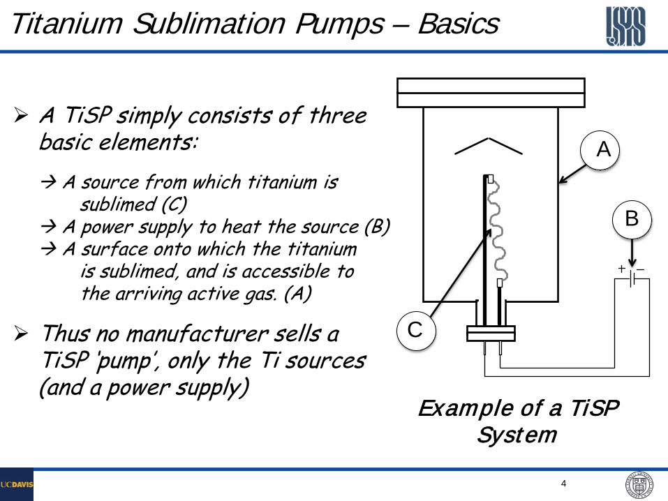
Example of a TiSP System
A TiSP simply consists of three basic elements: A source from which titanium is sublimed (C) A power supply to heat the source (B) A surface onto which the titanium is sublimed, and is accessible to the arriving active gas. (A)
Thus no manufacturer sells a TiSP ‘pump’, only the Ti sources (and a power supply)

5
Titanium Sources – Filamentary Types
Filaments made of 85%Ti-15%Mo are most common sources of titanium used in TiSPs.
The filament is resistively heated during sublimation process.
In most cartridges, multiple filaments are loaded.

6
Titanium Sources – Radiated Heating More suitable for very high throughput pumping application.
• Sources require operation at some level of standby power to maintain Titanium temperature above 900°C.
• Very inefficient heating, and require relatively high heating power.
Ref. “A Radiant Heated Titanium Sublimator,” Proc. 5th Int. Vacuum Congress, 1971, JVST 9 (1), 552 (1972)
Varian Vacuum
7
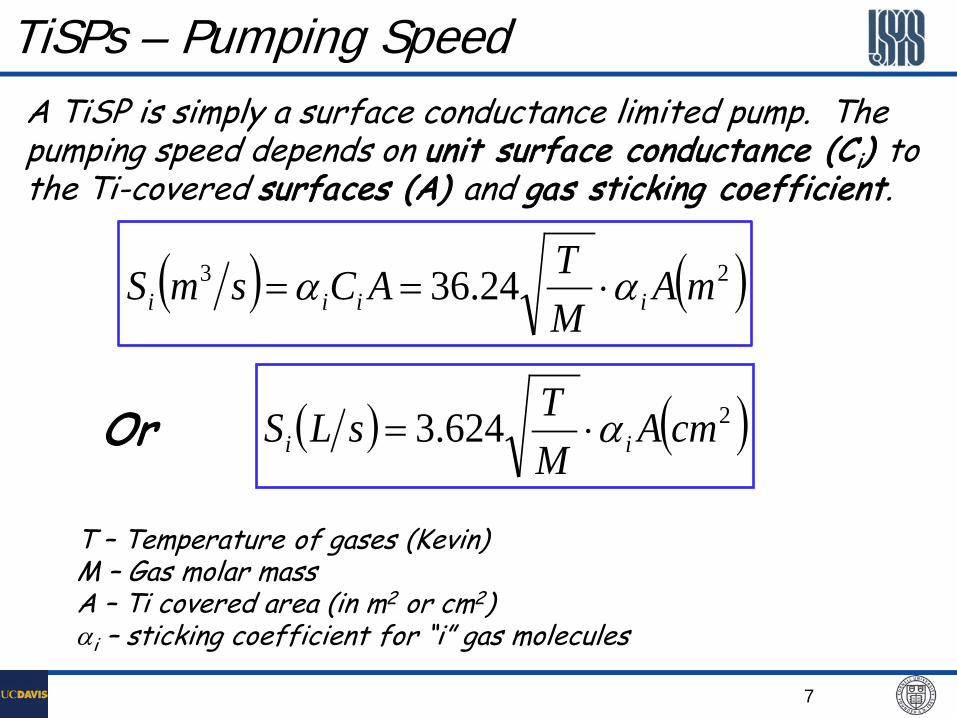
TiSPs – Pumping Speed A TiSP is simply a surface conductance limited pump. The pumping speed depends on unit surface conductance (Ci) to the Ti-covered surfaces (A) and gas sticking coefficient.
( ) ( )23 24.36 mAMTACsmS iiii αα ⋅==
T – Temperature of gases (Kevin) M – Gas molar mass A – Ti covered area (in m2 or cm2) αi – sticking coefficient for “i” gas molecules
( ) ( )2624.3 cmAMTsLS ii α⋅=Or

8
Sticking Coefficient
Ti layer: ~1016 atoms/cm2
Sticking coefficient is strongly gas reactivity dependent
For most active gases, the sticking coefficient decrease with adsorbed quantity, with various behavior, due to surface deactivation.
Ti film has very high capacity for hydrogen, indicating ‘bulk’ diffusion for dissociated H atoms.

9
Factors Influencing Sticking Coefficient
Thickness of Titanium film Ratio of pumping speed to Titanium sublimation rate Surface temperature at the time of sublimation Surface temperature at the time of gas sorption Film deposition process (batch or continuous) Gas species Gas desorption and synthesis at Titanium source Partial pressures of gases at time of sublimation Contamination of film by some gas Effects of film annealing Variations of surface and bulk diffusion processes

10
Pumped Gas
Displaced Gas
CH4 N2 H2 CO O2
CH4 no no no no
N2 yes no no no
H2 yes yes no no
CO yes yes yes no
O2 yes yes yes yes
αm <10-3 0.3 0.05 0.85 0.95
This is controversial and probably only true for CH4 and H2.
Pumped or/and Displaced Gases
11
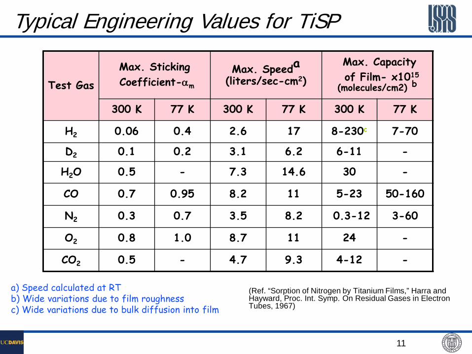
Typical Engineering Values for TiSP
Test Gas
Max. Sticking Coefficient-αm
Max. Speeda (liters/sec-cm2)
Max. Capacity of Film- x1015 (molecules/cm2) b
300 K 77 K 300 K 77 K 300 K 77 K
H2 0.06 0.4 2.6 17 8-230c 7-70
D2 0.1 0.2 3.1 6.2 6-11 -
H2O 0.5 - 7.3 14.6 30 -
CO 0.7 0.95 8.2 11 5-23 50-160
N2 0.3 0.7 3.5 8.2 0.3-12 3-60
O2 0.8 1.0 8.7 11 24 -
CO2 0.5 - 4.7 9.3 4-12 -
a) Speed calculated at RT b) Wide variations due to film roughness c) Wide variations due to bulk diffusion into film
(Ref. “Sorption of Nitrogen by Titanium Films,” Harra and Hayward, Proc. Int. Symp. On Residual Gases in Electron Tubes, 1967)

12
Pumping Capacity – Just an Example
13
Batch vs. Continuous Sublimation
For some high gas load, high throughout applications, Ti may be continuously sublimated. In the continuous sublimation mode, proper cooling must considered.
In most applications, Ti is periodically sublimated as the Ti layer is saturated. This is referred as “batch sublimation”. In a batch sublimation mode, the timing of the sublimation is usually rely on independent pressure measurement.
In batch-mode sublimation, one may choose various control modes: constant current, constant voltage or constant power.

14
Sublimation Mode – Constant Current
Constant current operation of Titanium filaments produces increases in sublimation rates early in the filament life.
This is probably due to the progressively leaner mixture of titanium in the filaments.
Filaments develop rougher surface textures as the mixture changes.
Rougher texture = greater surface area = higher emissivity = lower operating temperature = lower sublimation rates.

15
Sublimation Mode – Constant Voltage
Constant voltage operation is rarely done.
Constant voltage operation in conjunction with RT cycling produces more predictable sublimation rates
R(t) = Ro e- at
where Ro= initial sublimation rate a = constant t = cumulative sublimation time
Titanium sublimation rates are dependent on Ti and Mo proportions and the number of temperature cycles through the crystallographic transformation temperature.

16
Sublimation Mode – Constant Power At CESR, we choose a constant power approach for Ti
sublimation (with a LabView PID controller).
Using resistance change as a measure of sublimation rate, the constant power mode provide very long term stability of the sublimation rate.
Constant power mode also ensures longer lifetime of Ti filament.

17
TiSPs for Accelerators – Some Considerations
Gas throughput must be estimated for use of TiSPs, so that the sublimation period may be reasonable for the accelerator operations. Measures should be taken in design to maximize Ti covered surface area.
Baffles must be in place to block all line-of-sight between the Ti filaments and the particle beam space.
For very long term operations, Ti thin film peeling may be an issue. Orientation and placement of Ti filaments play a role in minimize particle generations to the beam space.
Ti filaments may become EMI antennae when not properly shielded against short bunched particle beam. Sometime RF filtering in necessary.
Adequate protections (mechanical and corrosive) are important for the electric feedthroughs on the Ti cartridges.

18
Peeling of Titanium Films • As Titanium builds-up on a pumping
surface, it will begin to peel.
• A typical thickness where peeling begins is 0.05 mm.
• Peeling produces dust particles and increases surface temperatures during sublimation.
• Because of peeling, pumping surfaces may require periodic cleaning (glass bead blasting and/or chemical cleaning).
• If peeling is a problem, a TSP was probably a bad choice or you are misusing the pumps.
19
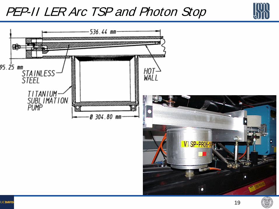
PEP-II LER Arc TSP and Photon Stop

20
DAFNE Collider TiSP
34.6 cm
Courtesy: C. Vaccarezza, INFN
Used at photon stops
Specially ordered cartridge with more filaments
Grooved interior surfaces to increase pumping speed and capacity
Yulin Li, January 14-18 2013 21
~ 16 m x 2
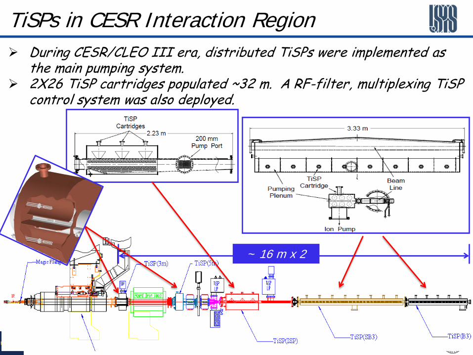
TiSPs in CESR Interaction Region During CESR/CLEO III era, distributed TiSPs were implemented as
the main pumping system. 2X26 TiSP cartridges populated ~32 m. A RF-filter, multiplexing TiSP
control system was also deployed.

22
Relay & EMI Filter Boxes
TiSP Chambers in CESR – A Close Look
23
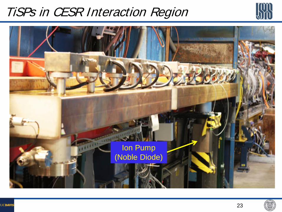
TiSPs in CESR Interaction Region
Ion Pump (Noble Diode)

24
TiSPs in CESR IR – Performance History

25
TiSPs in a Wiggler Vacuum Chamber
TiSP Plenum
TiSP Cartridge w/ Filter/Relay Box X8
TiSP Plenum Interior View
TiSP was incorporated in narrow gapped wiggler chamber for the CHESS G-line
Wall-side View
38-mm Gap

26
TiSPs in a Wiggler VC – Pumping Speed Calibrated leaks used to
measure pumping speed TiSPs sublimation: 200W-2min
Twice as capacity for CO as for N2, indicating dissociation of N2 on Ti.
Much higher capacity for H2.
27
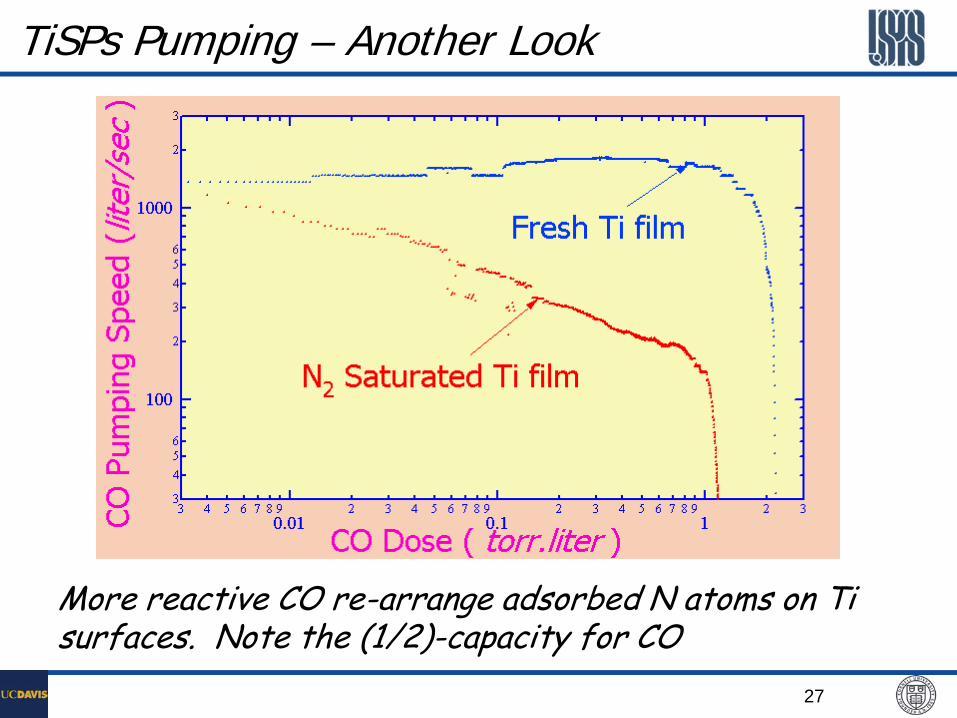
TiSPs Pumping – Another Look
More reactive CO re-arrange adsorbed N atoms on Ti surfaces. Note the (1/2)-capacity for CO
28
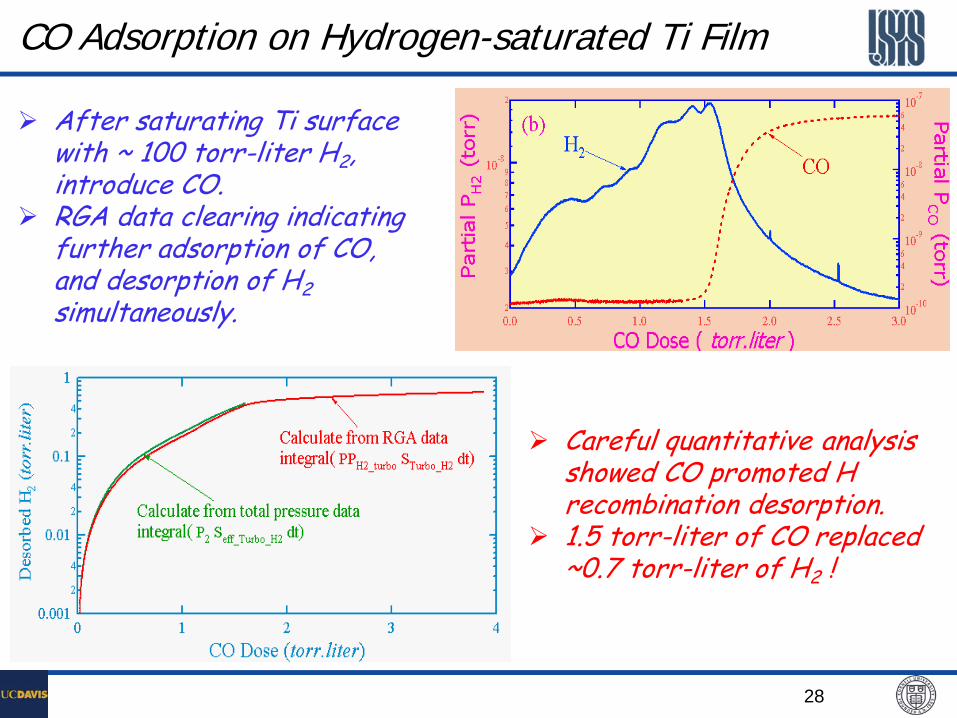
CO Adsorption on Hydrogen-saturated Ti Film
After saturating Ti surface with ~ 100 torr-liter H2, introduce CO.
RGA data clearing indicating further adsorption of CO, and desorption of H2 simultaneously.
Careful quantitative analysis showed CO promoted H recombination desorption.
1.5 torr-liter of CO replaced ~0.7 torr-liter of H2 !

29
Total pressure gauges data. Hard to tell the displacement of H2 by CO.
RGA data clearly showing CO replacing H2.
Important Partial Pressure Info

30
Session 4.3B Non-Evaporable Getters (NEGs)

31
NEGs – The Basics
Porous alloys with very large active metallic surface area, when activated.
Bulk Getters - gases diffuse into the interior of the getter material upon heating (activation).
Gases are categorized into four families based on their interactions with NEGs: 1. Hydrogen and its isotopes - adsorbed reversibly. 2. CO, CO2, O2, and N2 - adsorbed irreversibly. 3. H2O, hydrocarbons - adsorbed in a combination of
reversible and irreversible processes. Hydrocarbons are adsorbed very slowly.
4. Noble gases - not adsorbed at all.
32
• NEGs are primarily available only from: SAES Getters S.p.A. Viale Italia , 77 20020 Lainate (Milano) Italy
SAES Getters U.S.A., Inc. 1122 E. Cheyenne Mountain Blvd. Colorado Springs, CO 80906
Commercial NEGs
• NEGs are also available only from: Gamma Vacuum, Edwards Vacuum Inc. 2915 133rd Street West Shakopee, MN 55379 • USA
33
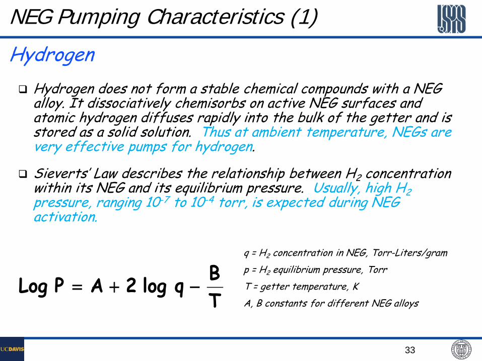
NEG Pumping Characteristics (1)
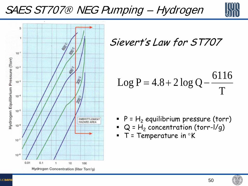
Hydrogen does not form a stable chemical compounds with a NEG alloy. It dissociatively chemisorbs on active NEG surfaces and atomic hydrogen diffuses rapidly into the bulk of the getter and is stored as a solid solution. Thus at ambient temperature, NEGs are very effective pumps for hydrogen.
Sieverts’ Law describes the relationship between H2 concentration within its NEG and its equilibrium pressure. Usually, high H2 pressure, ranging 10-7 to 10-4 torr, is expected during NEG activation.
TBq log 2AP Log −+=
q = H2 concentration in NEG, Torr-Liters/gram p = H2 equilibrium pressure, Torr T = getter temperature, K A, B constants for different NEG alloys
Hydrogen
34
NEG Pumping Characteristics (2) CO, CO2, O2, N2, other O-, C-containing molecules
Active gases are chemisorbed irreversibly by NEGs.
The chemical bonds of the gas molecules are broken on the surface of the NEG.
The various gas atoms are chemisorbed forming oxides, nitrides, and carbides.
At activation temperatures, these chemical bonds do not ‘break’. Instead, the elevated activation temperature promotes diffusion into the bulk of the NEG, to ‘regenerate’ active surface ‘sites’.

35
NEG Pumping Characteristics (3)
H2O and Hydrocarbons
• Water vapor and hydrocarbons are “cracked” on the surface of the NEG. • H2 is chemisorbed reversibly.
• O2 and C are chemisorbed irreversibly.
• However, hydrocarbons sorption efficiency at ambient
temperature is extremely low. However, HC pumping may be enhanced with ‘hot’ NEGs.
36
NEG Pumping Characteristics (4)
Noble gases
• NEGs do not sorb Ar, He, Kr, Xe.
• Ion pumps are required in combination with NEGs for pumping noble gases.

37
10
100
1000
10 4
0.01 0.1 1 10 100 1000
CO-25 CH2O-25 CCO-280 CH20-280 CH2-25 CH2-280 C
Pum
ping
Spe
ed (l
iters
/sec
)
Sorbed Quantity (Torr-liters)
At low throughput, NEG pumping speeds are constant, independent of pressure.
Pumping speeds usually increase at higher sorption temperature.
NEG Pumping Characteristics (5)

38
Activation Process for NEG

39
Application Notes for NEGs
0
20
40
60
80
100
120
0 5 10 15 20 25 30 35
N2 Air
Ref. SAES Getters
Perc
enta
ge o
f Ini
tial P
umpi
ng S
peed
Number of Exposures
NEG performance deteriorates due to successive exposures to air (oxygen and water) or N2.
Further improvement can be obtained if Argon is used as a protective gas, during long term storage .
NEG pumps should never be exposed to air while at temperatures higher than 50°C.
Degassing (or conditioning) of NEGs after initial pump-down.
Whenever practical, activate all NEGs in a system at the same time.

40
Pumping with Repeated Activations
Measured N2 pumping on a CapaciTorr D100 pump with repeated activation/saturation cycles w/o venting
41
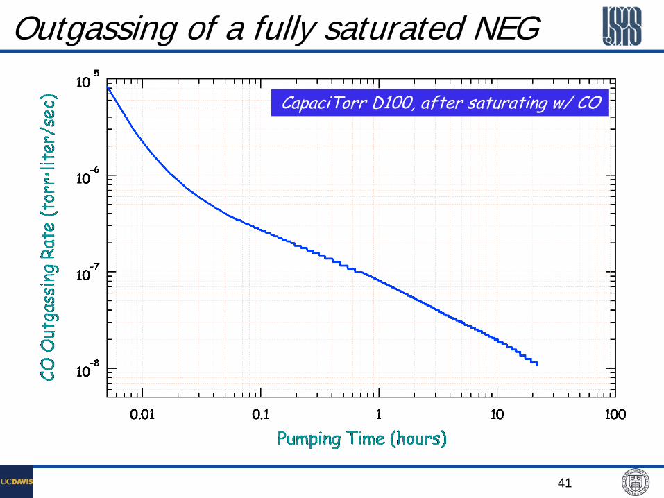
Outgassing of a fully saturated NEG
CapaciTorr D100, after saturating w/ CO

42
Take a look at NEG activation
CCG Data
This activation of a SAES’ CapaciTorr D100 pump shows typical behavior. (The pump was previously saturated with CO gas, after a 24-hr pumping.)
H2
CO
CO2
RGA Data
43
Examples of SAES Getter’s Available NEG Alloys

44
SAES ST101 Non-evaporable Getters
Metal alloy made up of 84% Zr, 16% Al.
First Zirconium based getter alloy introduced and still widely used today after 30 years.
The operating temperature range of ST101 is 0 to 450°C.
ST101 chemisorbs CO, CO2, H2O, N2, and O2 at high rates.
ST101 activates at temperatures from 550 to 900°C.
ST101 alloy has been replaced by new alloys with lower activation T. Ref. SAES Getters
ST 101 Alloy Activation Efficiency

45
SAES ST101 NEG – Pumping
Ref. SAES Getters

46
SAES ST101 NEG – Hydrogen Solubility

47
ST101 Surface Composition vs. Temperature
0
10
20
30
40
50
60
70
0 200 400 600 800 1000
C
O
Zr
Al
Surf
ace
Compo
sition
(Ato
mic %
)
Temperature (C) Ref. SAES Getters
Saturated ST101
Regenerated ST101

48
SAES ST707 Non-evaporable Getter
Metal alloy made up of 70% Zr, 24.6% Va, and 5.4% Fe.
The operating temperature range of ST707 is 20 to 100°C.
ST707 chemisorbs CO, CO2, H2O, N2, and O2 at high rates.
ST707 has much lower activation temperature.

49
SAES ST707 NEG Pumping Performance
50
SAES ST707 NEG Pumping – Hydrogen
T6116Qlog24.8PLog −+=
Sievert’s Law for ST707
P = H2 equilibrium pressure (torr) Q = H2 concentration (torr-l/g) T = Temperature in °K

51
ST707 Surface Composition vs. Temperature
0
10
20
30
40
50
60
70
0 100 200 300 400 500 600 700 800
COZrVFe
Surfa
ce C
ompo
sitio
n (A
tom
ic %
)
Temperature (C)

52
Other SAES NEG Alloys
ST 172 – ST707 + Zr. One of most used alloys, used in SAES’ CapaciTorr and NexTorr pump series.
ST175 – Ti and Mo powder mixture, sintered form.
ST185 – Ti-V alloy (obsolete !)
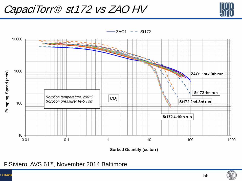
ZAO – a new Zr-based alloys, lower gas emissions, higher capacity

53
Examples of SAES Getter’s Available NEG Pumps

54
NEG Cartridge Pump Module – CapaciTorr
Complete compact pumping system, with matching controller for easy activation
NEG materials: st172 sintered blades/disks
Pump sizes from 50 l/s to 2000 l/s, for H2
For large sizes, the NEG cartridges are replaceable

55
CapaciTorr Pumping Performance
56
CapaciTorr st172 vs ZAO HV
F.Siviero AVS 61st, November 2014 Baltimore

57
NEG – Ion Pump Combination – NexTorr
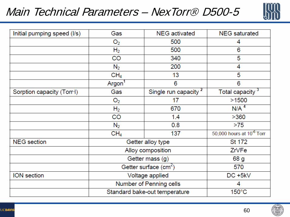
500 l/s VacIon Plus NexTorr D500-5

Yulin Li, January 19-23 2015 58
Available NexTorr Pumps from SAES

59
Pumping Performance – NexTorr
60
Main Technical Parameters – NexTorr D500-5

61
CapaciTorr and NexTorr Application Examples
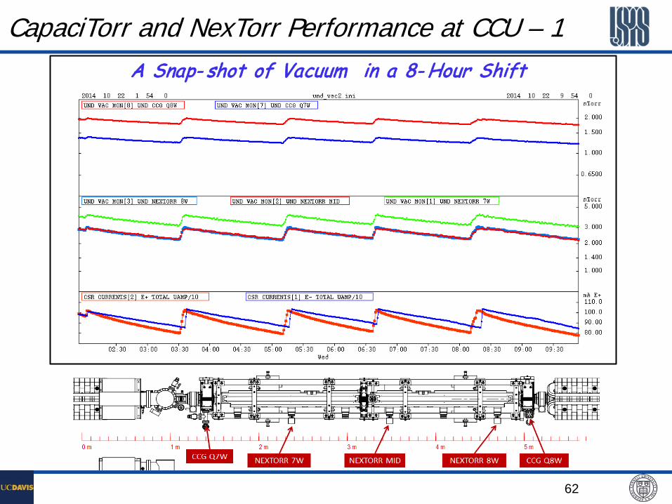
At a recent upgrade project for CESR/CHESS, a 3.5-m long undulator vacuum chamber was designed and installed to accommodate a pair of Cornell Compact Undulator (CCU)
Three NexTorr D100-5 and three CapaciTorr D200 pumps were used for vacuum pumping, taking full advantage of light weight of the NEGs.
62
CapaciTorr and NexTorr Performance at CCU – 1 A Snap- shot of Vacuum in a 8- Hour Shift

63
CapaciTorr and NexTorr Performance at CCU – 2
• The chamber vacuum conditioning are progressing as expected. • The NEGs were re-activated four times during regularly scheduled tunnel
access, to keep optimum pumping. • dP/dI values indicating ηPID approaches 10 -6 mol/ph @~100 Amp⋅hr beam dose.
NEG Activations
64
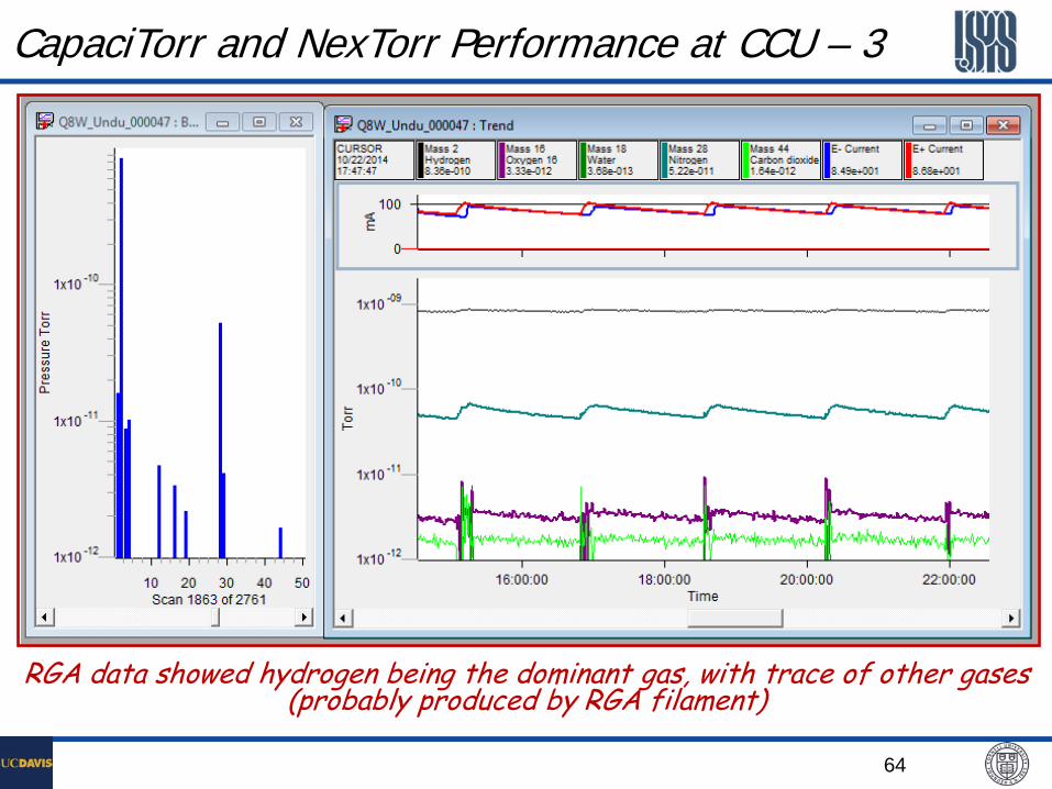
CapaciTorr and NexTorr Performance at CCU – 3
RGA data showed hydrogen being the dominant gas, with trace of other gases (probably produced by RGA filament)
65
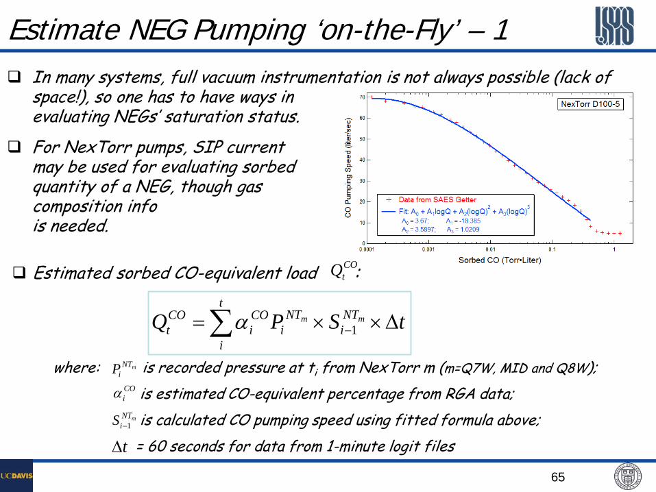
Estimate NEG Pumping ‘on-the-Fly’ – 1 In many systems, full vacuum instrumentation is not always possible (lack of
space!), so one has to have ways in evaluating NEGs’ saturation status.
For NexTorr pumps, SIP current may be used for evaluating sorbed quantity of a NEG, though gas composition info is needed.
∑ ∆××= −
t
i
NTi
NTi
COi
COt tSPQ mm
1α
where: is recorded pressure at ti from NexTorr m (m=Q7W, MID and Q8W);
is estimated CO-equivalent percentage from RGA data;
is calculated CO pumping speed using fitted formula above;
= 60 seconds for data from 1-minute logit files
mNTiP
COiα
mNTiS 1−
t∆
Estimated sorbed CO-equivalent load : COtQ
66
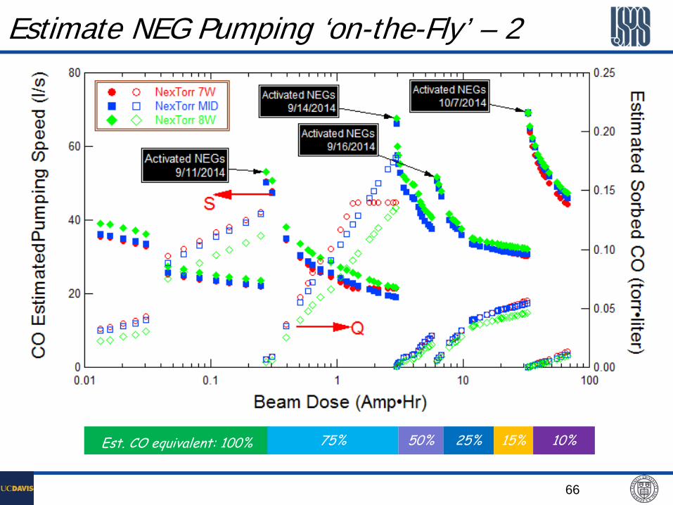
Estimate NEG Pumping ‘on-the-Fly’ – 2
Est. CO equivalent: 100% 75% 50% 25% 15% 10%

67
Other NEGs forms – Build your own pumps

68
Distributed Pumping with NEG strips
APS Beampipe with NEG strips
69
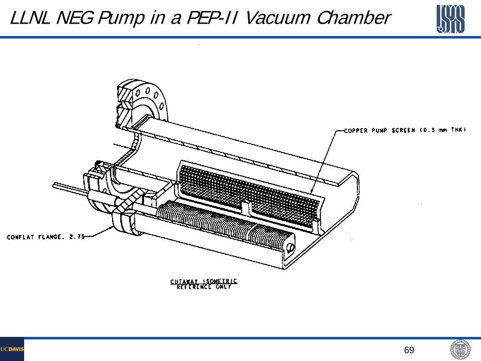
LLNL NEG Pump in a PEP-II Vacuum Chamber
70
Combination Pumping . . . Ion Pumps with TSP or NEG
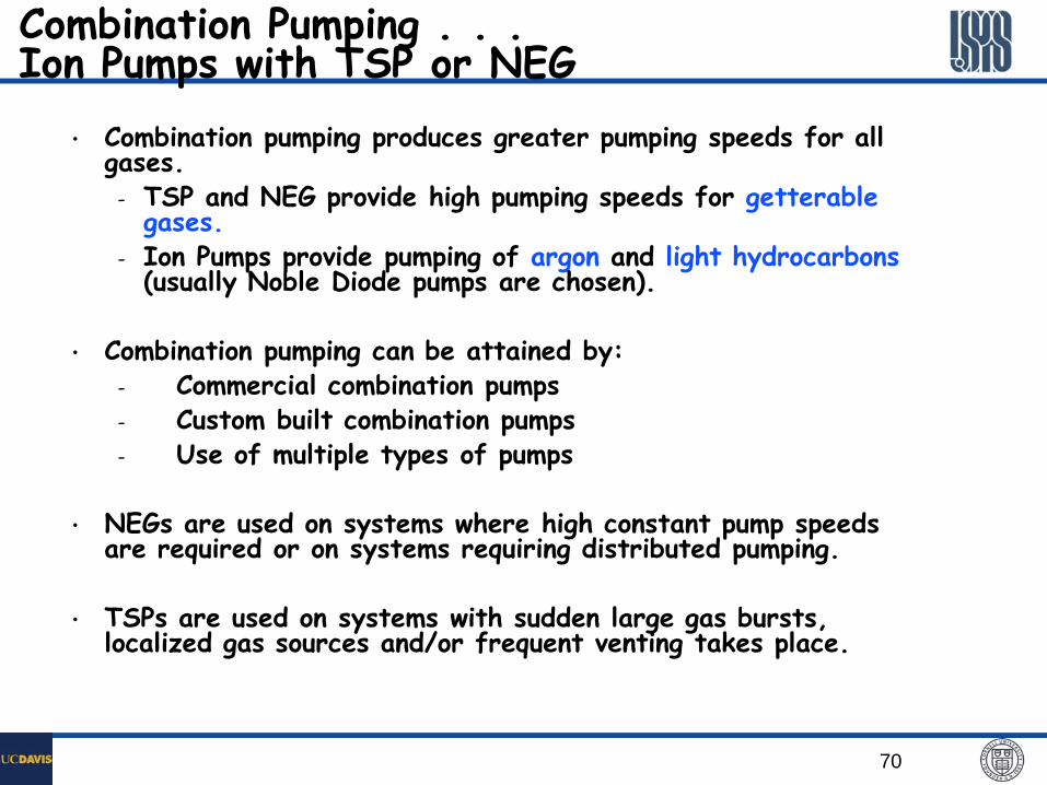
• Combination pumping produces greater pumping speeds for all gases.
- TSP and NEG provide high pumping speeds for getterable gases.
- Ion Pumps provide pumping of argon and light hydrocarbons (usually Noble Diode pumps are chosen).
• Combination pumping can be attained by: - Commercial combination pumps - Custom built combination pumps - Use of multiple types of pumps
• NEGs are used on systems where high constant pump speeds
are required or on systems requiring distributed pumping.
• TSPs are used on systems with sudden large gas bursts, localized gas sources and/or frequent venting takes place.
71
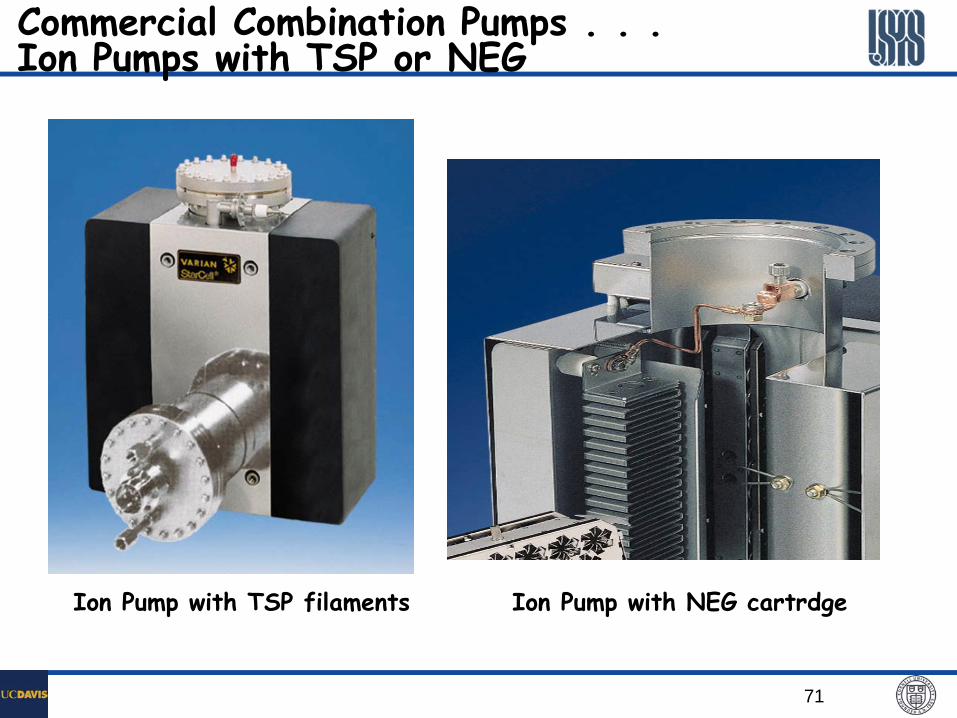
Commercial Combination Pumps . . . Ion Pumps with TSP or NEG
Ion Pump with TSP filaments Ion Pump with NEG cartrdge

72
Particle Issues with NEGs and Mitigations Most NEG pumping elements are formed through powder metallurgy,
either through cold-press or sintering processes. Thus the NEGs are prone to particulate creation, if not treated.
Particulates creation from NEGs can be a major concern for many UHV systems, such as superconductivity RF cavities, HV DC photon-cathode guns, etc.
Strips with cold-press NEG materials are mechanically less stable than sintered disks/blades. So careful placement consideration should be taken in using these NEG elements.
NEG pumps using sintered materials (such as NexTorr, CapaciTorr) can be cleaned to achieve clean-room compatibility. The proven cleaning methods include N2-blowing and solvent rinsing (in a Clean-Room condition).
However, cleaned sintered NEG elements may still generate particulates during initial activations. This is currently under further investigations.
73
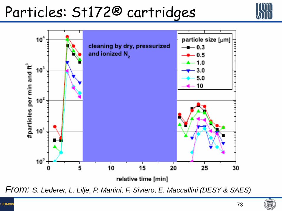
Particles: St172® cartridges
From: S. Lederer, L. Lilje, P. Manini, F. Siviero, E. Maccallini (DESY & SAES)
74
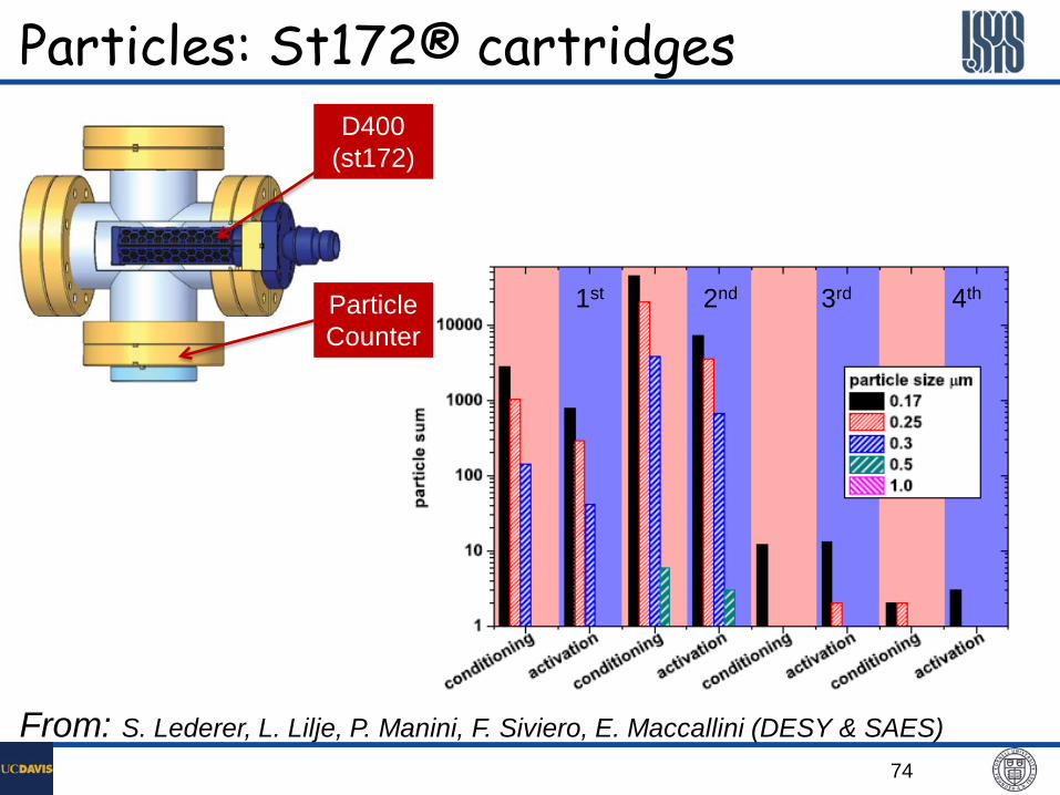
1st 2nd 3rd 4th
Particles: St172® cartridges
From: S. Lederer, L. Lilje, P. Manini, F. Siviero, E. Maccallini (DESY & SAES)
D400 (st172)
Particle Counter

75
Measurements at INFN Milan
Particles: St172 vs ZAO HV1 Laser particle counter under N2 flushing

76
Solvent Cleaning of Sintered NEG
A test by SAES Getters showed no effect on NEG pumping after methanol dipping

77
NEG Thin Film – Integrated Pumping
NEG Coating
Discrete Pumping
Distributed Pumping
Integrated Pumping

78
NEG Thin Film – Benefits

79
Typical Sputtering Arrangement – A CLASSE Setup
• Cathode – Twisted wires
• Electric field (ion energy) ~ 600 V
• Magnetic field : 200 ~ 500 Gauss
• Sputtering gas : Ar or Kr P = 2 ~ 20 mtorr
Deposition of NEG Thin Films
DC or Magnetron Sputtering arrangement is commonly used.
Coating surface cleanness is essential for good adhesion
Sputtering gas purity extremely important

80
NEG Thin Film Characteristics Most commonly deposited NEG thin films have
elementary composition of ZrxVyTiz, with x, y, z, close to unity.
Stoichiometric balanced thin film tend to have lower activation temperature, probably due to smaller grain sizes.
Pumping can be achieved at activation temperature as low as 150°C, though typical ~250°C. Thus an in-situ bakeout can activate the NEG coating.
Typical NEG thin film thickness: 2~4 µm.

81
NEG Coating Pumping Performance (1) Tact=350°C

82
NEG Coating Pumping Performance (2)
Pumping Speed vs. Gas-load Activation Temperature Dependence (48-hr activation)

83
NEG Film Total Capacity & Aging Effects
• Total pumping capacity of a NEG thin film depends on the film’s solubility to oxygen, carbon, nitrogen, etc., and the film thickness
Using solubility of 5%, 1-nm saturated surface oxide layer Estimated saturation/venting cycles for 1 µm NEG film > 50
• Gradual aging is a deterioration of the thin film performance due to accumulation of oxygen in the film
Reduction of pumping speed and capacity
Increase of activation temperature

84
NEG Film Aging Effect

85
NEG Film Aging – More

86
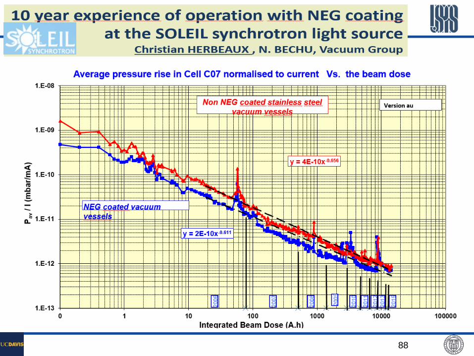
Successful Applications of NEG Coatings • NEG coating is an idea solution for long narrow-gapped undulator
vacuum chambers • All LHC warm beampipes were NEG coated. • ESRF has had a very successful experience with the NEG-coated
undulator chambers. • RHIC coated ~600m of warm beampipes to suppress e-Cloud and
associated abnormal pressure rises, which resulted in significant increase in heavy ion beam performances.
• Other new 3rd generation SR light sources, such as SOLEIL and DIAMOND, also used the NEG coatings for the undulator chambers.
• A NEG Coating Workshop (45th IUVSTA Workshop) was held at Catania Italy, in April 2006.

87
Comparison of SR facilities in attendance @ 80th IUVSTA
Courtesy of Jason Carter of APS
88

89
CERN’s NEG Coating Facility
~ 8
m

90
manifold
chambers
extensions
Solenoid L=8m φ=60cm
3mm wires of
Ti, Zr and V
CERN’s NEG Coating Facility – Details

91
CERN’s NEG Coating Production More than 1300 chambers coated with TiZrV NEG for the LHC.
Standard chambers are 7 m long, 80 mm diameter.

92
ESRF’s NEG Coating Facility
Motorized Air-cool Solenoid (500 G @100Amp)
Extruded Al-Chamber 5-m long, 11-mm Gap
A New NEG Coating Building @ESRF

93
IntegraTorr – SAES Getters’ NEG Coating SAES Getters is licensed by CERN to provide commercial NEG
coating services.
All components to be coated by SAES are cleaned by CERN facility, to ensure good thin film adhesiveness.
Known projects used this services: RHIC, CesrTA, etc.

94
Hydrogen Embrittlement of NEGs are well known

95

96
• Both TiSPs and NEGs are great in deal with hydrogen gas load, the main gas in an UHV system
• If space available, TiSPs are the first choice Much lower cost More operational friendly ‘Un-limited’ capacity
• However, space is always tight in accelerators, NEGs are more favorable They are more expensive, but similar to the ion pumps NEGs are usually user-ready, little design involved Capacity vs. dynamic gas-load needs to be evaluated.
• Some practical questions regarding NEGs How to reduce hydrogen from NEGs ? Should the NEGs be thoroughly de-hydrogen before installation ? Or is that possible ? What’s sources of hydrogen in the commercial NEG module/cartridge (in the NEG materials, or in the heating elements) ? What’s the best way to passivate NEGs for air exposure ?
NEGs or TiSPs