t2 arthrodesis nailing system - stryker meded · t2 arthrodesis nailing system ... arthrodesis of...
TRANSCRIPT
1
T2 Arthrodesis Nailing System
Operative Technique
2
Contributing Surgeons
This publication sets forth detailed recommended procedures for using Stryker Osteosynthesis devices and instruments.
It offers guidance that you should heed, but, as with any such technical guide, each surgeon must consider the particular needs of each patient and make appropriate adjustments when and as required.
A workshop training is required prior to first surgery.
All non-sterile devices must be cleaned and sterilized before use. Follow the instructions provided in our reprocessing guide (L24002000). Multi-component instruments must be disassembled for cleaning. Please refer to the corresponding assembly/disassembly instructions.
See package insert (L22000007) for a complete list of potential adverse effects, contraindications, warnings and precautions. The surgeon must discuss all relevant risks, including the finite lifetime of the device, with the patient, when necessary.
Warning: All bone screws referenced in this document here are not approved for screw attachment or fixation to the posterior elements (pedicles) of the cervical, thoracic or lumbar spine.
Stephen IncavoMD University of VermontDepartment of Orthopaedics & RehabilitationBurlington/Vermont, USA
Prof. Dr. Dr. Gunther O. HofmannChief of Surgical ServicesMedical Director of Halle Trauma CenterHalle, GermanyDirector of Trauma DepartmentFriedrich-Schiller-UniversityJena, Germany
Knee Arthrodesis Nailing System
Reference1. Incavo S., Lily J. ,Churchill
Bartlett C., Arthrodesis of the Knee: Experience with Intramedullary Nailing. Journal of Arthroplasty 15 (7) 871−876, 2000
2. Hofmann G.O., Therapeutische Optionen bei persistierendem Kniegelenkinfekt, Trauma Berufskrankheit 5 (2003), 221−224
3
Contents
Page
1. Introduction 4
Implant Features 4
Instrument Features 4
2. Indications, Precautions & Contraindications 5
Indications 5
Precautions 5
Relative Contraindications 5
3. Technical Details 6
System Specifications 6
4. Operative Technique 7
Pre-operative Planning 7
Patient Positioning 7
Knee Incision 7
Hip Incision and Entry Point 7
Reaming 8
Nail Assembly 8
Nail Insertion Preparation 9
Nail Insertion 10
Guided Locking Mode (via Targeting Device) 11
Static Locking 12
Apposition/Compression Locking Mode 14
Freehand Distal Locking 15
Ordering Information – Implants 16
Ordering Information – Instruments 17

4
Introduction
The T2 Nailing System represents Stryker s latest and most com-prehensive development of the original intra-medullary principles presented by Prof. Gerhard Küntscher in 1940.
Stryker has created a new generation locking nail system, bringing together all the capabilities and benefits of separate nailing systems to create a single, integrated surgical resource for fixation of long bones.
In addition to the T2 Femoral, Tibial, and Humeral Nailing Systems, Stryker developed the T2 Arthrodesis Nail to provide treatment of Knee Arthrodesis.
Through the development of a common, streamlined and intuitive surgical approach, both in principle and in detail, the T2 Arthrodesis Nail offers significantly increased speed and functionality for the treatment of Knee Arthrodesis as well as simpli-fying the training requirements for all personnel involved.
The T2 Arthrodesis Nail is the realization of strong biomechanical intramedullary stabilization using small caliber cannulated implants for internal fixation of long bones.
The design of the T2 Arthrodesis Nail features a unique curvature which incorporates both femur antecurvature and knee valgus bend. This design dictates the need for both left and right implants providing an improved fit for each patient’s individual needs. All T2 Arthrodesis Nail implants are made of Type II anodized titanium alloy (Ti6Al4V) for enhanced biomechanical and biomedical performance. All implants are provided in sterile packaging.
Implant FeaturesThe T2 Arthrodesis Nail is inserted with the existing T2 Basic Set, Long together with the Femur Indication Set.
Note:The core instruments of the T2 system provide the platform for all current and future Stryker Nailing Systems, thereby reducing complexity and inventory. Refer to the T2 Femoral Nailing System Operative Technique (REF B1000004) and T2 Tibial Nailing System Operative Technique (REF B1000005) for more detailed system protocols.
Instrument Features
5
Indications, Precautions and Contraindication
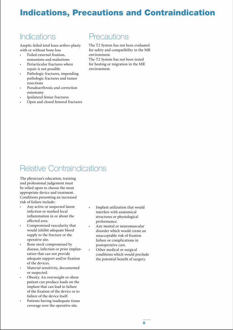
IndicationsAseptic failed total knee arthro-plasty with or without bone loss
Failed external fixation, •nonunions and malunionsPeriarticular fractures where •repair is not possiblePathologic fractures, impending •pathologic fractures and tumor resectionsPseudoarthrosis and correction •osteotomyIpsilateral femur fractures•Open and closed femoral fractures•
Relative ContraindicationsThe physician’s education, training and professional judgement must be relied upon to choose the most appropriate device and treatment. Conditions presenting an increased risk of failure include:
Any active or suspected latent •infection or marked local inflammation in or about the affected area.Compromised vascularity that •would inhibit adequate blood supply to the fracture or the operative site.Bone stock compromised by •disease, infection or prior implan-tation that can not provide adequate support and/or fixation of the devices.Material sensitivity, documented •or suspected.Obesity. An overweight or obese •patient can produce loads on the implant that can lead to failure of the fixation of the device or to failure of the device itself.Patients having inadequate tissue •coverage over the operative site.
Implant utilization that would •interfere with anatomical structures or physiological performance.Any mental or neuromuscular •disorder which would create an unacceptable risk of fixation failure or complications in postoperative care.Other medical or surgical •conditions which would preclude the potential benefit of surgery.
Precautions The T2 System has not been evaluated for safety and compatibility in the MR environment. The T2 System has not been tested for heating or migration in the MR environment.

6
Technical Details
System Specifications
0 mm
Two Nails, Left and Right
Diameters: 11.5 & 13mmLengths: 540 − 780mm in 40mm increments
Screws, End caps & Compression Screw (See Page 16 for complete description and catalog numbers)
0mm
32.5mm35mm
45mm47.5mm
60mm
75 mm
35 mm
25 mm
15mm5mm
10mm
Compression Range:Total Length of SlotLess Screw Diameter (−)
Maximum Movement of Screw
7
Operative Technique
Pre-operative PlanningAn X-Ray Template (1806-0011) is available for pre-operative planning. Implant sizing is best determined using full length A/P and Lateral X-Rays of both the affected and contralateral legs. C.T. Scan for canal diameter and leg length may be useful. The knee should be placed in 5−10˚ of flexion and 5˚ valgus. The leg should be 1cm shorter than the opposite side. This position allows for more normal gait and foot clearance during walking. Ultimately, 1 cm of leg shortening is the goal, therefore in cases with more significant bone loss, additional flexion should be avoided to minimize additional shortening.
Patient positioning is surgeon dependent. The patient may be positioned supine (elevate the affected hip), lateral or semi-lateral on a radiolucent table. Use image intensification (A/P and Lateral) for confirmation throughout each step.
The nail length is surgeon dependent with regards to the individual situation of the patient and with regards on how long the nail should extend into the Tibia.
Patient Positioning
Nail Length
A vertical skin incision is made extending from the femoral condylar region to the tibial tubercule, followed by a parapatellar capsular incision. In cases with a previous incision, this one could be used. Knee arthroplasty instruments may be used to recut tibial and femoral surfaces.
A skin incision is made beginning at the level of the Greater Trochanter extending proximal and slightly posterior, in line with the Gluteus Muscle, exposing the Piriformis Fossa. Alternatively, the Tip of the Greater Trochanter can be located by palpation, and a horizontal skin incision is made from the Greater Trochanter to the Iliac Crest. The medullary canal is opened with the curved awl (1806-0040), or with a 3×285mm K-Wire (1806-0050) and Ø12mm Rigid Reamer (1806-2014) combination.
Alternatively, a minimal skin incision of the hip region can be made if the femoral canal is reamed in retrograde fashion from the knee joint. To accomplish this, the 3×1250mm Ball Tip Guide Wire (1806-1250S) is advanced from the distal femoral canal proximally to the greater trochanteric / piriformis fossa region.
Warning:Avoid the femoral neck. The Guide Wire is then gently advanced through the cortex by gently tapping the strike plate on the Guide Wire Handle/Chuck assembly. Fluoroscopic visualization is necessary for this step. Once the Guide Wire exits the bone, it is retrieved through a small skin incision made over the tip of the Guide Wire.
Hip Incision and Entry Point
Knee Incision
Noting any deformity of the axis of the tibial shaft, and using either the Awl or Rigid Reamer over the K-Wire, open the anterior central medial aspect of the tibia using the tibial tubercle as a reference to the medullary canal.
Insert the 1250mm Ball Tip Guide Wire (1806-1250S) from the hip through the knee and advance into the tibial shaft to the depth at which you want the nail to end.
The Guide Wire Ruler (1806-0022) features dedicated marks to identify the to be choosen nail length when using the 1250mm Guide Wire.
Caution:Use image intensification (A/P and Lateral) for confirmation throughout each step.
8
Reaming
Operative Technique
Using a 885mm Bixcut Modular Reamer Shaft (REF Numbers on page 16), reaming is commenced in 0.5mm increments. Generally, the femur is reamed 1.5 – 2.0mm larger than the diameter of the nail selected, and the tibia is reamed line to line. The proximal end of the tibial shaft may be over-reamed if there is any question of final Femoral-Tibial alignment. Final determination of how much to ream either the femur or the tibia must be made by the surgeon based on many factors including bone quality and whether the nail will be cross-locked with screws distally in the tibia. As stated above, in some cases, surgeons may opt to use standard length Guide Wires and Reamers and ream the femur in retrograde fashion first and then the tibia separately.
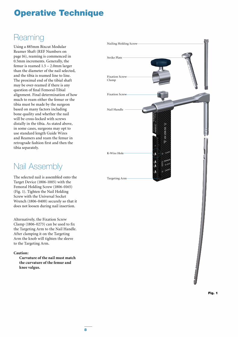
Nail AssemblyThe selected nail is assembled onto the Target Device (1806-1005) with the Femoral Holding Screw (1806-0165) (Fig. 1). Tighten the Nail Holding Screw with the Universal Socket Wrench (1806-0400) securely so that it does not loosen during nail insertion.
Alternatively, the Fixation Screw Clamp (1806-0273) can be used to fix the Targeting Arm to the Nail Handle. After clamping it on the Targeting Arm the knob will tighten the sleeve to the Targeting Arm.
Caution:Curvature of the nail must match the curvature of the femur and knee valgus.
Fig. 1
Nail Handle
Nailing Holding Screw
Strike Plate
Fixation Screw
Fixation Screw Clamp
Targeting Arm
K-Wire Hole

9
Nail Insertion Preparation
Fig. 5
Fig. 4
Upon completion of reaming, the appropriate size nail is ready for insertion over the 3×1250mm Ball Tip Guide Wire (1806-1250S).The Slotted Hammer can be used on the Strike Plate, or if dense bone is encountered, the Universal Rod (1806-0110) may be attached to the Nail Holding Screw and used in con-junction with the Slotted Hammer to insert the nail (Fig. 2).
Caution:Prior to insertion, check for correct assembly into the nail by passing a drill Bit through the Target Device and through the nail holes to help check alignment. DO NOT hit on the Targeting Device.
When locking the nail in the Static Mode, the nail is countersunk a minimum of 5mm (Fig. 4). When the implant is inserted in the dynamic mode, without active apposition/compression, or when the implant is inserted with active apposition/compression, the recommended depth of insertion is 15mm (Fig. 5).
Caution:The system offers the option •of different locking modes. In addition to static locking, a controlled dynamization or a controlled apposition/compression can be mechanically applied with an optional internal compression screw.In cases where the compression •feature is used, the tibia must be locked with cross-locking screws before the compression is applied proximally. Up to 10mm of mechanical compression can be applied.Additionally, the 3×285mm •K-Wire may be inserted through the Target Device which indicates the junction of the nail and insertion post (see Fig. 1).
Fig. 2
Static
Dynamic
Apposition/Compression
2 mm
5 mm
10 mm
15 mm
Fig. 3
Operative Technique
10
Operative Technique
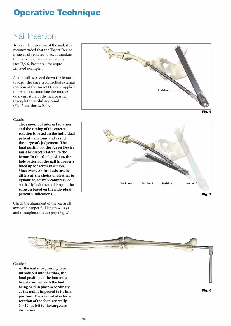
To start the insertion of the nail, it is recommended that the Target Device is internally rotated to accommodate the individual patient’s anatomy (see Fig. 6, Position 1 for appro-ximated example).
As the nail is passed down the femur towards the knee, a controlled external rotation of the Target Device is applied to better accommodate the unique dual curvature of the nail passing through the medullary canal (Fig. 7 position 2, 3, 4).
Caution: The amount of internal rotation, and the timing of the external rotation is based on the individual patient’s anatomy and as such, the surgeon’s judgement. The final position of the Target Device must be directly lateral to the femur. In this final position, the hole pattern of the nail is properly lined up for screw insertion. Since every Arthrodesis case is different, the choice of whether to dynamize, actively compress, or statically lock the nail is up to the surgeon based on the individual patient’s indications.
Check the alignment of the leg in all axis with proper full length X-Rays and throughout the surgery (Fig. 8).
Caution: As the nail is beginning to be introduced into the tibia, the final position of the foot must be determined with the foot being held in place accordingly as the nail is impacted to its final position. The amount of external rotation of the foot, generally 0 − 10 , is left to the surgeon’s discretion.
Fig. 6
Fig. 8
Position 2Position 3Position 4
Fig. 7
Position 1
Position 1
Nail Insertion
11
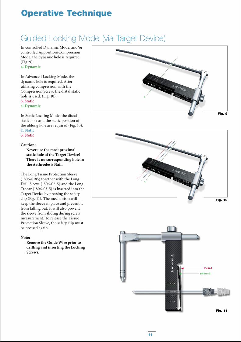
In controlled Dynamic Mode, and/or controlled Apposition/Compression Mode, the dynamic hole is required (Fig. 9).4. Dynamic
In Advanced Locking Mode, the dynamic hole is required. After utilizing compression with the Compression Screw, the distal static hole is used. (Fig. 10).3. Static4. Dynamic
In Static Locking Mode, the distal static hole and the static position of the oblong hole are required (Fig. 10).2. Static3. Static
Caution:Never use the most proximal static hole of the Target Device! There is no corresponding hole in the Arthrodesis Nail.
The Long Tissue Protection Sleeve (1806-0185) together with the Long Drill Sleeve (1806-0215) and the Long Trocar (1806-0315) is inserted into the Target Device by pressing the safety clip (Fig. 11). The mechanism will keep the sleeve in place and prevent it from falling out. It will also prevent the sleeve from sliding during screw measurement. To release the Tissue Protection Sleeve, the safety clip must be pressed again.
Note:Remove the Guide Wire prior to drilling and inserting the Locking Screws.
Fig. 11
Fig. 9
3
4
4
Fig. 10
2
Operative Technique
locked
released
Guided Locking Mode (via Target Device)
12
50mm
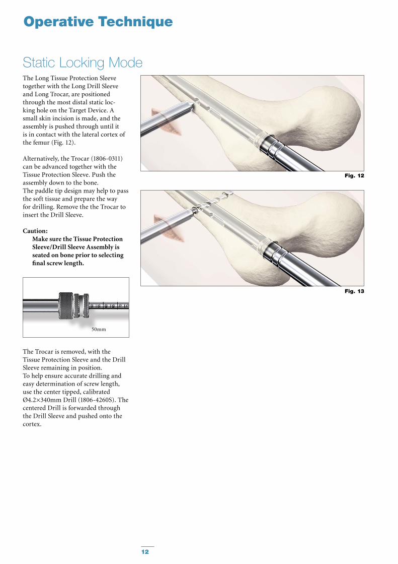
The Long Tissue Protection Sleeve together with the Long Drill Sleeve and Long Trocar, are positioned through the most distal static loc-king hole on the Target Device. A small skin incision is made, and the assembly is pushed through until it is in contact with the lateral cortex of the femur (Fig. 12).
Alternatively, the Trocar (1806-0311) can be advanced together with the Tissue Protection Sleeve. Push the assembly down to the bone.The paddle tip design may help to pass the soft tissue and prepare the way for drilling. Remove the the Trocar to insert the Drill Sleeve.
Caution: Make sure the Tissue Protection Sleeve/Drill Sleeve Assembly is seated on bone prior to selecting final screw length.
The Trocar is removed, with the Tissue Protection Sleeve and the Drill Sleeve remaining in position.To help ensure accurate drilling andeasy determination of screw length, use the center tipped, calibrated Ø4.2×340mm Drill (1806-4260S). The centered Drill is forwarded through the Drill Sleeve and pushed onto the cortex.
Fig. 12
Fig. 13
Operative Technique
Static Locking Mode
13
Fig. 15
Fig. 14
Operative Technique
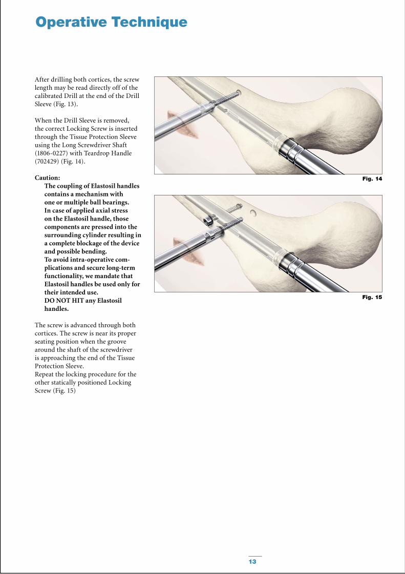
After drilling both cortices, the screw length may be read directly off of the calibrated Drill at the end of the Drill Sleeve (Fig. 13).
When the Drill Sleeve is removed, the correct Locking Screw is inserted through the Tissue Protection Sleeve using the Long Screwdriver Shaft (1806-0227) with Teardrop Handle (702429) (Fig. 14).
Caution: The coupling of Elastosil handles contains a mechanism with one or multiple ball bearings. In case of applied axial stress on the Elastosil handle, those components are pressed into the surrounding cylinder resulting in a complete blockage of the device and possible bending.To avoid intra-operative com-plications and secure long-term functionality, we mandate that Elastosil handles be used only for their intended use. DO NOT HIT any Elastosil handles.
The screw is advanced through both cortices. The screw is near its proper seating position when the groove around the shaft of the screwdriver is approaching the end of the Tissue Protection Sleeve.Repeat the locking procedure for the other statically positioned Locking Screw (Fig. 15)
14
Note:Distal freehand static locking with at least two Fully Threaded Locking Screws must be performed prior to applying active, controlled apposition/compression to the fusion site.
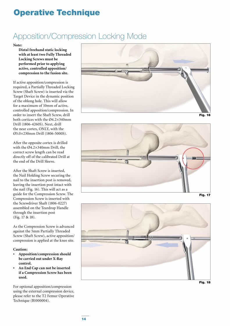
If active apposition/compression is required, a Partially Threaded Locking Screw (Shaft Screw) is inserted via the Target Device in the dynamic position of the oblong hole. This will allow for a maximum of 10mm of active, controlled apposition/compression. In order to insert the Shaft Screw, drill both cortices with the Ø4.2×340mm Drill (1806-4260S). Next, drill the near cortex, ONLY, with the Ø5.0×230mm Drill (1806-5000S).
After the opposite cortex is drilled with the Ø4.2×340mm Drill, the correct screw length can be read directly off of the calibrated Drill at the end of the Drill Sleeve.
After the Shaft Screw is inserted, the Nail Holding Screw securing the nail to the insertion post is removed, leaving the insertion post intact with the nail (Fig. 16). This will act as a guide for the Compression Screw. The Compression Screw is inserted with the Screwdriver Shaft (1806-0227) assembled on the Teardrop Handle through the insertion post (Fig. 17 & 18).
As the Compression Screw is advanced against the 5mm Partially Threaded Screw (Shaft Screw), active apposition/compression is applied at the knee site.
Caution: Apposition/compression should •be carried out under X-Ray control.An End Cap can not be inserted •if a Compression Screw has been used.
For optional apposition/compression using the external compression device, please refer to the T2 Femur Operative Technique (B1000004).
Fig. 17
Fig. 16
Fig. 18
Operative Technique
Apposition/Compression Locking Mode
15
Freehand Distal Locking
Operative Technique
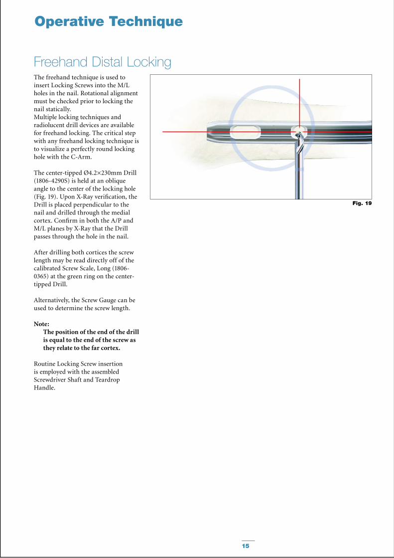
The freehand technique is used to insert Locking Screws into the M/L holes in the nail. Rotational alignment must be checked prior to locking the nail statically. Multiple locking techniques and radiolucent drill devices are available for freehand locking. The critical step with any freehand locking technique is to visualize a perfectly round locking hole with the C-Arm.
The center-tipped Ø4.2×230mm Drill (1806-4290S) is held at an oblique angle to the center of the locking hole (Fig. 19). Upon X-Ray verification, the Drill is placed perpendicular to the nail and drilled through the medial cortex. Confirm in both the A/P and M/L planes by X-Ray that the Drill passes through the hole in the nail.
After drilling both cortices the screw length may be read directly off of the calibrated Screw Scale, Long (1806-0365) at the green ring on the center-tipped Drill.
Alternatively, the Screw Gauge can be used to determine the screw length.
Note:The position of the end of the drill is equal to the end of the screw as they relate to the far cortex.
Routine Locking Screw insertion is employed with the assembled Screwdriver Shaft and Teardrop Handle.
Fig. 19
16
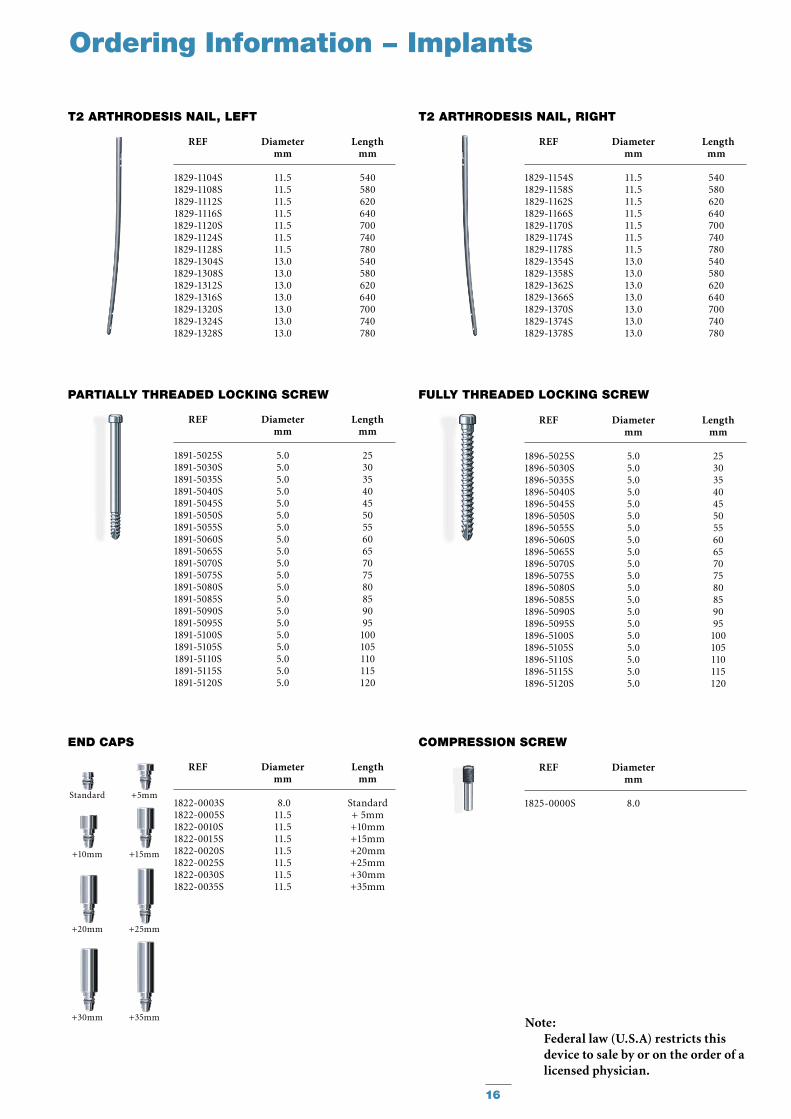
Ordering Information − Implants
Note:Federal law (U.S.A) restricts this device to sale by or on the order of a licensed physician.
REF Diameter Length mm mm
1829-1104S 11.5 540 1829-1108S 11.5 580 1829-1112S 11.5 620 1829-1116S 11.5 640 1829-1120S 11.5 700 1829-1124S 11.5 740 1829-1128S 11.5 780 1829-1304S 13.0 540 1829-1308S 13.0 580 1829-1312S 13.0 620 1829-1316S 13.0 640 1829-1320S 13.0 700 1829-1324S 13.0 740 1829-1328S 13.0 780
T2 ARTHRODESIS NAIL, LEFT
REF Diameter Length mm mm
1829-1154S 11.5 540 1829-1158S 11.5 580 1829-1162S 11.5 620 1829-1166S 11.5 640 1829-1170S 11.5 700 1829-1174S 11.5 740 1829-1178S 11.5 780 1829-1354S 13.0 540 1829-1358S 13.0 580 1829-1362S 13.0 620 1829-1366S 13.0 640 1829-1370S 13.0 700 1829-1374S 13.0 740 1829-1378S 13.0 780
T2 ARTHRODESIS NAIL, RIGHT
COmPRESSION SCREw
PARTIALLy THREADED LOCKING SCREw
REF Diameter Length mm mm
1891-5025S 5.0 25 1891-5030S 5.0 30 1891-5035S 5.0 35 1891-5040S 5.0 40 1891-5045S 5.0 45 1891-5050S 5.0 50 1891-5055S 5.0 55 1891-5060S 5.0 60 1891-5065S 5.0 65 1891-5070S 5.0 70 1891-5075S 5.0 75 1891-5080S 5.0 80 1891-5085S 5.0 85 1891-5090S 5.0 90 1891-5095S 5.0 95 1891-5100S 5.0 100 1891-5105S 5.0 105 1891-5110S 5.0 110 1891-5115S 5.0 115 1891-5120S 5.0 120
+5mm
+10mm +15mm
Standard
REF Diameter Length mm mm
1822-0003S 8.0 Standard1822-0005S 11.5 + 5mm1822-0010S 11.5 +10mm1822-0015S 11.5 +15mm1822-0020S 11.5 +20mm1822-0025S 11.5 +25mm1822-0030S 11.5 +30mm1822-0035S 11.5 +35mm
END CAPS
+20mm +25mm
+30mm +35mm
FuLLy THREADED LOCKING SCREw
REF Diameter Length mm mm
1896-5025S 5.0 25 1896-5030S 5.0 30 1896-5035S 5.0 35 1896-5040S 5.0 40 1896-5045S 5.0 45 1896-5050S 5.0 50 1896-5055S 5.0 55 1896-5060S 5.0 60 1896-5065S 5.0 65 1896-5070S 5.0 70 1896-5075S 5.0 75 1896-5080S 5.0 80 1896-5085S 5.0 85 1896-5090S 5.0 90 1896-5095S 5.0 95 1896-5100S 5.0 100 1896-5105S 5.0 105 1896-5110S 5.0 110 1896-5115S 5.0 115 1896-5120S 5.0 120
REF Diameter mm
1825-0000S 8.0
17
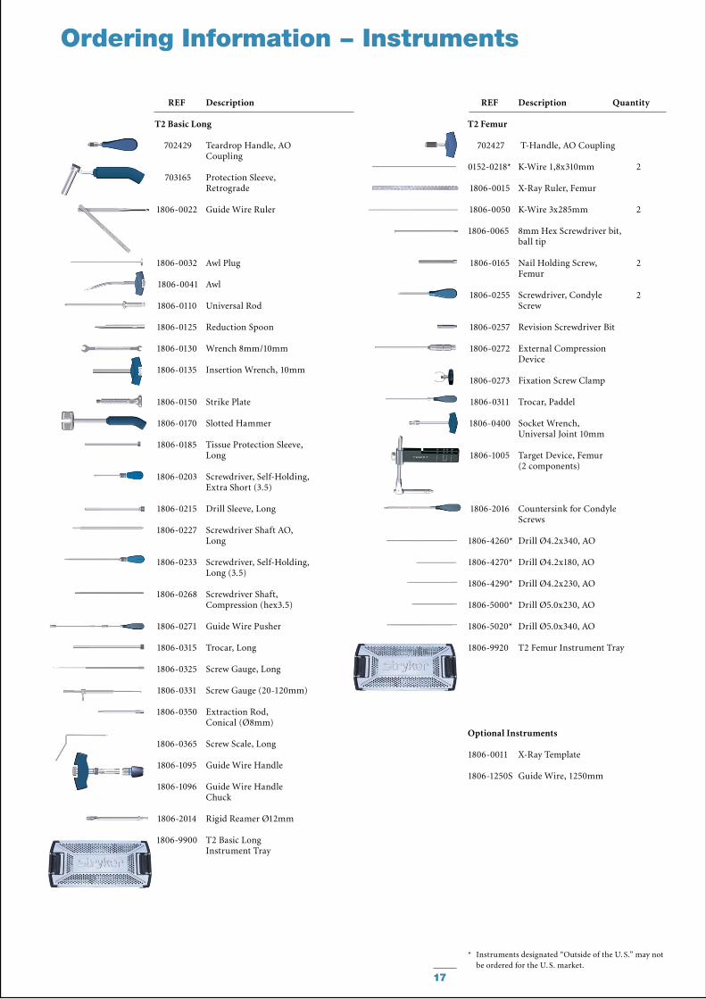
Ordering Information − Instruments
REF Description
T2 Basic Long
702429 Teardrop Handle, AO Coupling
703165 Protection Sleeve, Retrograde
1806-0022 Guide Wire Ruler
1806-0032 Awl Plug
1806-0041 Awl
1806-0110 Universal Rod
1806-0125 Reduction Spoon
1806-0130 Wrench 8mm/10mm
1806-0135 Insertion Wrench, 10mm
1806-0150 Strike Plate
1806-0170 Slotted Hammer
1806-0185 Tissue Protection Sleeve, Long
1806-0203 Screwdriver, Self-Holding, Extra Short (3.5)
1806-0215 Drill Sleeve, Long
1806-0227 Screwdriver Shaft AO, Long
1806-0233 Screwdriver, Self-Holding, Long (3.5)
1806-0268 Screwdriver Shaft, Compression (hex3.5)
1806-0271 Guide Wire Pusher
1806-0315 Trocar, Long
1806-0325 Screw Gauge, Long
1806-0331 Screw Gauge (20-120mm)
1806-0350 Extraction Rod, Conical (Ø8mm)
1806-0365 Screw Scale, Long
1806-1095 Guide Wire Handle
1806-1096 Guide Wire Handle Chuck
1806-2014 Rigid Reamer Ø12mm
1806-9900 T2 Basic Long Instrument Tray
REF Description Quantity
T2 Femur
702427 T-Handle, AO Coupling
0152-0218* K-Wire 1,8x310mm 2
1806-0015 X-Ray Ruler, Femur
1806-0050 K-Wire 3x285mm 2
1806-0065 8mm Hex Screwdriver bit, ball tip
1806-0165 Nail Holding Screw, 2 Femur
1806-0255 Screwdriver, Condyle 2 Screw
1806-0257 Revision Screwdriver Bit
1806-0272 External Compression Device
1806-0273 Fixation Screw Clamp
1806-0311 Trocar, Paddel
1806-0400 Socket Wrench, Universal Joint 10mm
1806-1005 Target Device, Femur (2 components)
1806-2016 Countersink for Condyle Screws
1806-4260* Drill Ø4.2x340, AO
1806-4270* Drill Ø4.2x180, AO
1806-4290* Drill Ø4.2x230, AO
1806-5000* Drill Ø5.0x230, AO
1806-5020* Drill Ø5.0x340, AO
1806-9920 T2 Femur Instrument Tray
Optional Instruments
1806-0011 X-Ray Template
1806-1250S Guide Wire, 1250mm
* Instruments designated “Outside of the U. S.” may not be ordered for the U. S. market.
18
Ordering Information – Instruments
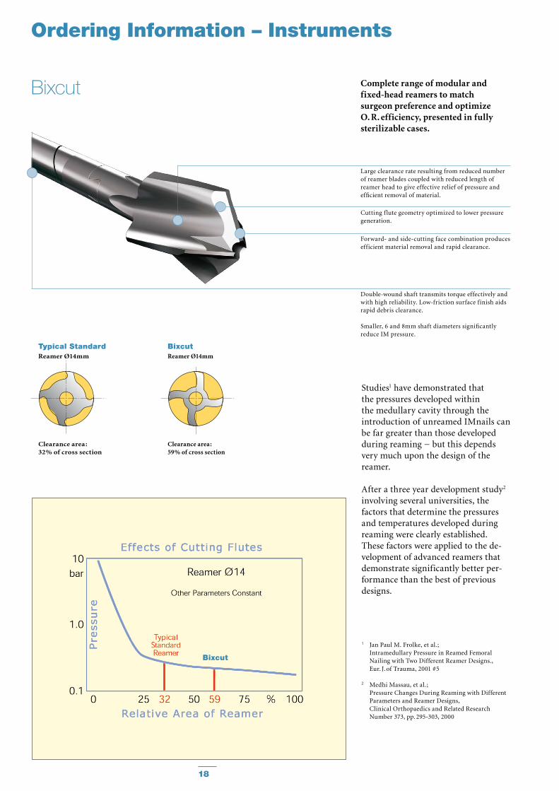
Complete range of modular and fixed-head reamers to match surgeon preference and optimize O. R. efficiency, presented in fully sterilizable cases.
Studies1 have demonstrated that the pressures developed within the medullary cavity through the introduction of unreamed IMnails can be far greater than those devel oped during reaming − but this depends very much upon the design of the reamer.
After a three year development study2 involving several universities, the factors that determine the pressures and temperatures developed during reaming were clearly established. These factors were applied to the de -velopment of advanced reamers that demonstrate significantly better per -form ance than the best of previous designs.
1 Jan Paul M. Frolke, et al. ; Intramedullary Pressure in Reamed Femoral
Nailing with Two Different Reamer Designs., Eur. J. of Trauma, 2001 #5
2 Medhi Massau, et al.; Pressure Changes During Reaming with Different
Parameters and Reamer Designs, Clinical Orthopaedics and Related Research
Number 373, pp. 295-303, 2000
Large clearance rate resulting from reduced number of reamer blades coupled with reduced length of reamer head to give effective relief of pressure and efficient removal of material.
Cutting f lute geometry optimized to lower pressure generation.
Forward- and side-cutting face combination produces efficient material removal and rapid clearance.
Double-wound shaft transmits torque effectively and with high reliability. Low-friction surface finish aids rapid debris clearance.
Smaller, 6 and 8mm shaft diameters significantly reduce IM pressure.
Bixcut
Typical StandardReamer Ø14mm
Clearance area :32% of cross section
BixcutReamer Ø14mm
Clearance area :59% of cross section
Bixcut
19
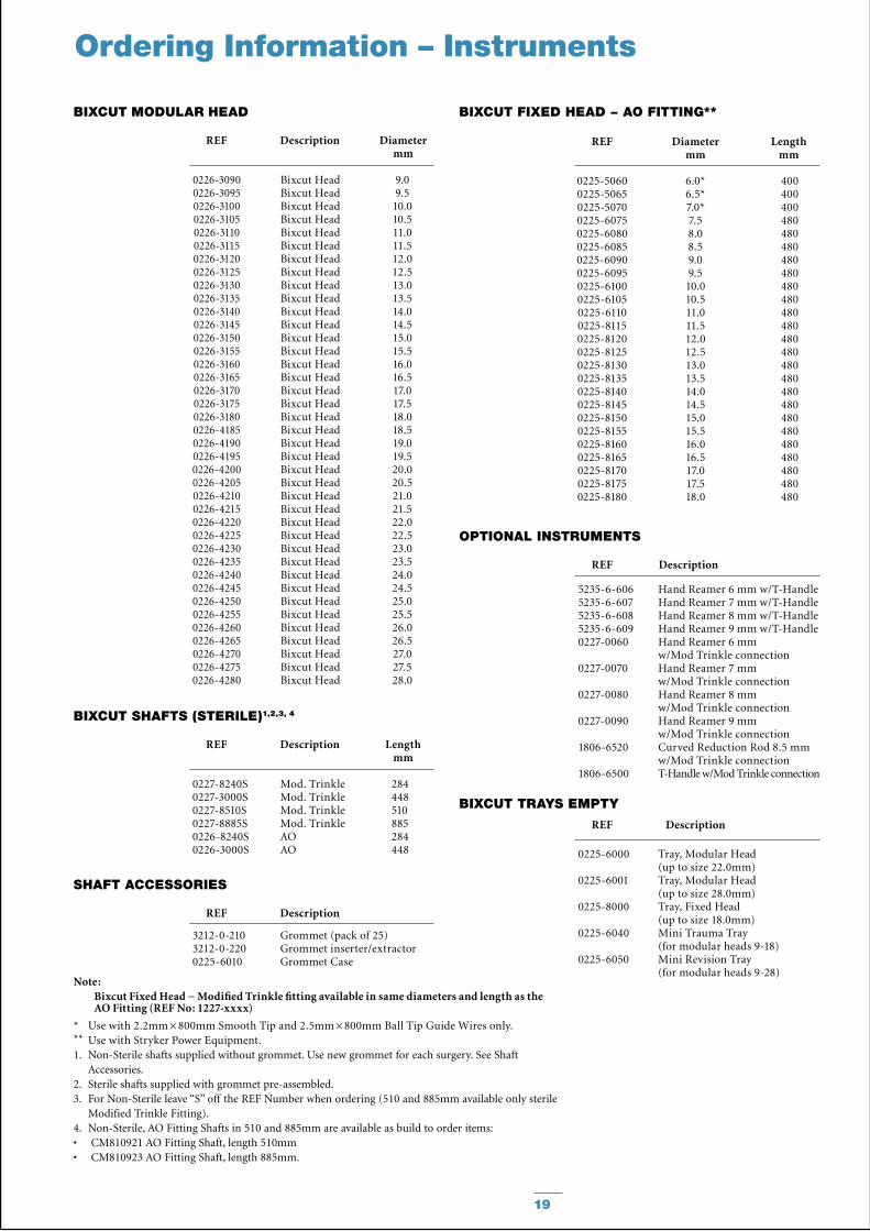
REF Description Diameter mm
BIxCuT mODuLAR HEAD
REF Diameter Length mm mm
BIxCuT FIxED HEAD − AO FITTING**
REF Description Length mm
BIxCuT SHAFTS (STERILE)1,2,3, 4
REF Description
SHAFT ACCESSORIES
REF Description
BIxCuT TRAyS EmPTy
Ordering Information – Instruments
REF Description
OPTIONAL INSTRumENTS
5235-6-606 Hand Reamer 6 mm w/T-Handle 5235-6-607 Hand Reamer 7 mm w/T-Handle 5235-6-608 Hand Reamer 8 mm w/T-Handle 5235-6-609 Hand Reamer 9 mm w/T-Handle 0227-0060 Hand Reamer 6 mm
w/Mod Trinkle connection 0227-0070 Hand Reamer 7 mm
w/Mod Trinkle connection 0227-0080 Hand Reamer 8 mm
w/Mod Trinkle connection 0227-0090 Hand Reamer 9 mm
w/Mod Trinkle connection 1806-6520 Curved Reduction Rod 8.5 mm
w/Mod Trinkle connection 1806-6500 T-Handle w/Mod Trinkle connection
0226-30900226-30950226-31000226-31050226-31100226-31150226-31200226-31250226-31300226-31350226-31400226-31450226-31500226-31550226-31600226-31650226-31700226-31750226-31800226-41850226-41900226-41950226-42000226-42050226-42100226-42150226-42200226-42250226-42300226-42350226-42400226-42450226-42500226-42550226-42600226-42650226-42700226-42750226-4280
Bixcut HeadBixcut HeadBixcut HeadBixcut HeadBixcut HeadBixcut HeadBixcut HeadBixcut HeadBixcut HeadBixcut HeadBixcut HeadBixcut HeadBixcut HeadBixcut HeadBixcut HeadBixcut HeadBixcut HeadBixcut HeadBixcut HeadBixcut HeadBixcut HeadBixcut HeadBixcut HeadBixcut HeadBixcut HeadBixcut HeadBixcut HeadBixcut HeadBixcut HeadBixcut HeadBixcut HeadBixcut HeadBixcut HeadBixcut HeadBixcut HeadBixcut HeadBixcut HeadBixcut HeadBixcut Head
9.09.5
10.010.511.011.512.012.513.013.514.014.515.015.516.016.517.017.518.018.519.019.520.020.521.021.522.022.523.023.524.024.525.025.526.026.527.027.528.0
0227-8240S Mod. Trinkle 284 0227-3000S Mod. Trinkle 448 0227-8510S Mod. Trinkle 510 0227-8885S Mod. Trinkle 885 0226-8240S AO 284 0226-3000S AO 448 0225-6000 Tray, Modular Head
(up to size 22.0mm) 0225-6001 Tray, Modular Head (up to size 28.0mm) 0225-8000 Tray, Fixed Head (up to size 18.0mm) 0225-6040 Mini Trauma Tray (for modular heads 9-18) 0225-6050 Mini Revision Tray (for modular heads 9-28)
0225-50600225-50650225-50700225-60750225-60800225-60850225-60900225-60950225-61000225-61050225-61100225-81150225-81200225-81250225-81300225-81350225-81400225-81450225-81500225-81550225-81600225-81650225-81700225-81750225-8180
6.0*6.5*7.0*7.58.08.59.09.5
10.010.511.011.512.012.513.013.514.014.515.015.516.016.517.017.518.0
400400400480480480480480480480480480480480480480480480480480480480480480480
3212-0-210 Grommet (pack of 25) 3212-0-220 Grommet inserter/extractor 0225-6010 Grommet Case
Note: Bixcut Fixed Head − Modified Trinkle fitting available in same diameters and length as the AO Fitting (REF No: 1227-xxxx)
* Use with 2.2mm × 800mm Smooth Tip and 2.5mm × 800mm Ball Tip Guide Wires only.** Use with Stryker Power Equipment.1. Non-Sterile shafts supplied without grommet. Use new grommet for each surgery. See Shaft
Accessories.2. Sterile shafts supplied with grommet pre-assembled.3. For Non-Sterile leave “S” off the REF Number when ordering (510 and 885mm available only sterile
Modified Trinkle Fitting).4. Non-Sterile, AO Fitting Shafts in 510 and 885mm are available as build to order items:
CM810921 AO Fitting Shaft, length 510mm• CM810923 AO Fitting Shaft, length 885mm.•
Stryker Trauma GmbHProf.-Küntscher-Straße 1-5D-24232 SchönkirchenGermany
www.osteosynthesis.stryker.com
This document is intended solely for the use of healthcare professionals. A surgeon must always rely on his or her own professional clinical judgment when deciding whether to use a particular product when treating a particular patient. Stryker does not dispense medical advice and recommends that surgeons be trained in the use of any par-ticular product before using it in surgery. The information presented in this brochure is intended to demonstrate a Stryker product. Always refer to the package insert, product label and/or user instructions including the instructions for Cleaning and Sterilization (if applicable) before using any Stryker products. Products may not be available in all markets. Product availability is subject to the regulatory or medical practices that govern individual markets. Please contact your Stryker representative if you have questions about the availability of Stryker products in your area.
Stryker Corporation or its divisions or other corporate affiliated entities own, use or have applied for the following trademarks or service marks: Stryker, BixCut and T2.
All other trademarks are trademarks of their respective owners or holders.The products listed above are CE marked.
Literature Number : B1000010LOT F0710
Copyright © 2010 Stryker