t132 revision 2 information added, 25 march 2018 … · this manual is intended to assist owners...
TRANSCRIPT
Lada/Sewmaster/Cresta T132
Service/Repair Guide
Revision 2 – Additional information added, 25 March 2018
Produced by Dan Hopgood
Introduction
This manual is intended to assist owners with routine and service maintenance of the Lada/Sewmaster/Cresta
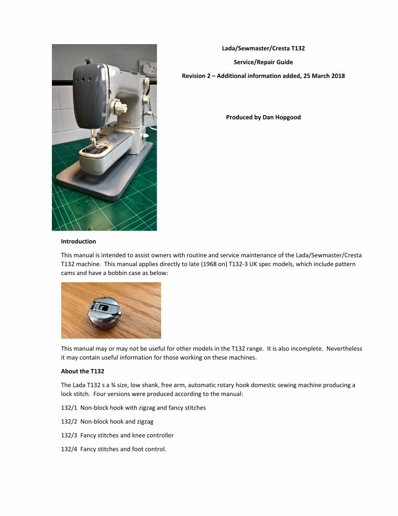
T132 machine. This manual applies directly to late (1968 on) T132‐3 UK spec models, which include pattern
cams and have a bobbin case as below:
This manual may or may not be useful for other models in the T132 range. It is also incomplete. Nevertheless
it may contain useful information for those working on these machines.
About the T132
The Lada T132 s a ¾ size, low shank, free arm, automatic rotary hook domestic sewing machine producing a
lock stitch. Four versions were produced according to the manual:
132/1 Non‐block hook with zigzag and fancy stitches
132/2 Non‐block hook and zigzag
132/3 Fancy stitches and knee controller
132/4 Fancy stitches and foot control.
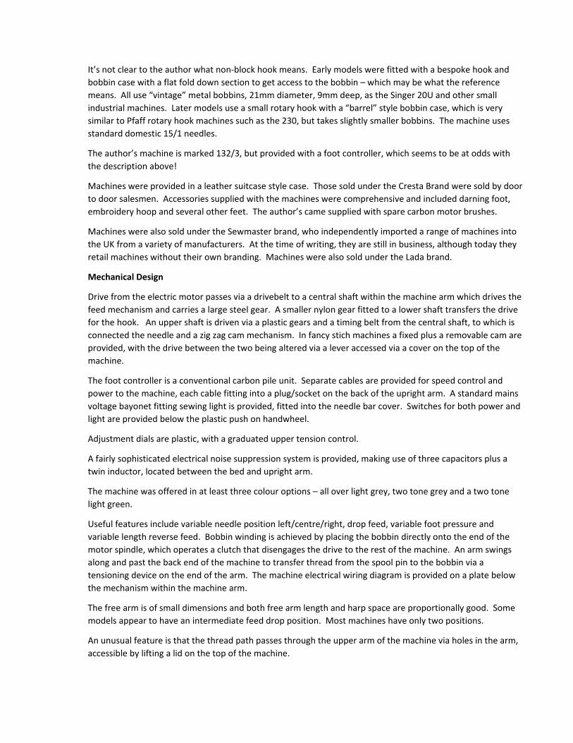
It’s not clear to the author what non‐block hook means. Early models were fitted with a bespoke hook and
bobbin case with a flat fold down section to get access to the bobbin – which may be what the reference
means. All use “vintage” metal bobbins, 21mm diameter, 9mm deep, as the Singer 20U and other small
industrial machines. Later models use a small rotary hook with a “barrel” style bobbin case, which is very
similar to Pfaff rotary hook machines such as the 230, but takes slightly smaller bobbins. The machine uses
standard domestic 15/1 needles.
The author’s machine is marked 132/3, but provided with a foot controller, which seems to be at odds with
the description above!
Machines were provided in a leather suitcase style case. Those sold under the Cresta Brand were sold by door
to door salesmen. Accessories supplied with the machines were comprehensive and included darning foot,
embroidery hoop and several other feet. The author’s came supplied with spare carbon motor brushes.
Machines were also sold under the Sewmaster brand, who independently imported a range of machines into
the UK from a variety of manufacturers. At the time of writing, they are still in business, although today they
retail machines without their own branding. Machines were also sold under the Lada brand.
Mechanical Design
Drive from the electric motor passes via a drivebelt to a central shaft within the machine arm which drives the
feed mechanism and carries a large steel gear. A smaller nylon gear fitted to a lower shaft transfers the drive
for the hook. An upper shaft is driven via a plastic gears and a timing belt from the central shaft, to which is
connected the needle and a zig zag cam mechanism. In fancy stich machines a fixed plus a removable cam are
provided, with the drive between the two being altered via a lever accessed via a cover on the top of the
machine.
The foot controller is a conventional carbon pile unit. Separate cables are provided for speed control and
power to the machine, each cable fitting into a plug/socket on the back of the upright arm. A standard mains
voltage bayonet fitting sewing light is provided, fitted into the needle bar cover. Switches for both power and
light are provided below the plastic push on handwheel.
Adjustment dials are plastic, with a graduated upper tension control.
A fairly sophisticated electrical noise suppression system is provided, making use of three capacitors plus a
twin inductor, located between the bed and upright arm.
The machine was offered in at least three colour options – all over light grey, two tone grey and a two tone
light green.
Useful features include variable needle position left/centre/right, drop feed, variable foot pressure and
variable length reverse feed. Bobbin winding is achieved by placing the bobbin directly onto the end of the
motor spindle, which operates a clutch that disengages the drive to the rest of the machine. An arm swings
along and past the back end of the machine to transfer thread from the spool pin to the bobbin via a
tensioning device on the end of the arm. The machine electrical wiring diagram is provided on a plate below
the mechanism within the machine arm.
The free arm is of small dimensions and both free arm length and harp space are proportionally good. Some
models appear to have an intermediate feed drop position. Most machines have only two positions.
An unusual feature is that the thread path passes through the upper arm of the machine via holes in the arm,
accessible by lifting a lid on the top of the machine.
The machine is relatively light at 8kg and has a manufacturer quoted top speed of 1400stitches per minute.
Maximum quoted stitch width and length are both 4mm. Foot lift is 7mm.
About Lada Sewing Machines
The history of the Lada Company can be traced back to 1881 when the Minerava brand was established in
Vienna. The company relocated to Opava in what is now the Czech Republic in 1913. A factory was
established at Boskovice in 1936, which in WWII produced armaments for the German Wehrmacht. After the
war in the subsequent Soviet dominated era, the brand of Lada Sobeslav was created and the stage for design
and production of the T132 was set. Production of the T132 started in 1957 and ended in 1968 with a decision
by the management to end domestic machine production. There have been changes of company structure
since, but industrial sewing machine production in Boskovice continues to this day under the Minerva brand.
Machine Adjustments
Presser bar – height adjustment and alignment
1 Open the front cover
2 Raise the presser foot
3 Remove the screw in the top of the machine that provides foot pressure to eliminate all foot
pressure
4 Fit the standard zig zag presser foot
5 Loosen the clamp screw on the presser bar
6 Adjust the height of the presser foot for a 7mm gap between the needle plate and presser foot.
Ideally use a distance piece 7mm thick.
7 Partly tighten the clamp screw sufficient that the presser foot won’t drop and remove the spacer
8 Align the presser foot square to the machine
9 Fully tighten the presser bar clamp screw.
Needle bar – height adjustment
1 Time the hook
2 Fit a 80/12 needle
3 Turn the handwheel to raise the needle to its highest position
4 Remove the free arm top cover by removing the two allen key bolts
5 Rotate the handwheel to bring the needle to its lowest position
6 Continue to rotate the handwheel to raise the needle until the hook point is directly behind
the needle. At this point, the top of the needle hole should be about 2.5mm below the hook
point. Adjust as necessary.
7 Ensure the needle clamp screw is square to the line of the machine.
8 Tighten the clamp screw.
9 Replace needle and free arm cover and check for correct sewing operation.
To set Feed dog at the correct height
Yet to be written
To set the distance between the needle and the hook point
The distance between hook and needle point is determined by the position of the hook on its spindle. To alter
the clearance:
1 Remove the free arm top cover and open the covedr over the hook area.
2 Remove old oil from the three mounting screws on the side of the hook, accessed from the front
end of the machine. Set the machine for maximum width zig zag and with a well fitting
screwdriver, loosen the mounting screws.
3 Without rotating the hook, move the hook forward or backward as required to achieve a
minimum clearance to the hook point. Tighten one of the screws and re‐check on full zig zag.
Once happy, tighten all the screws.
4 Check the hook timing.
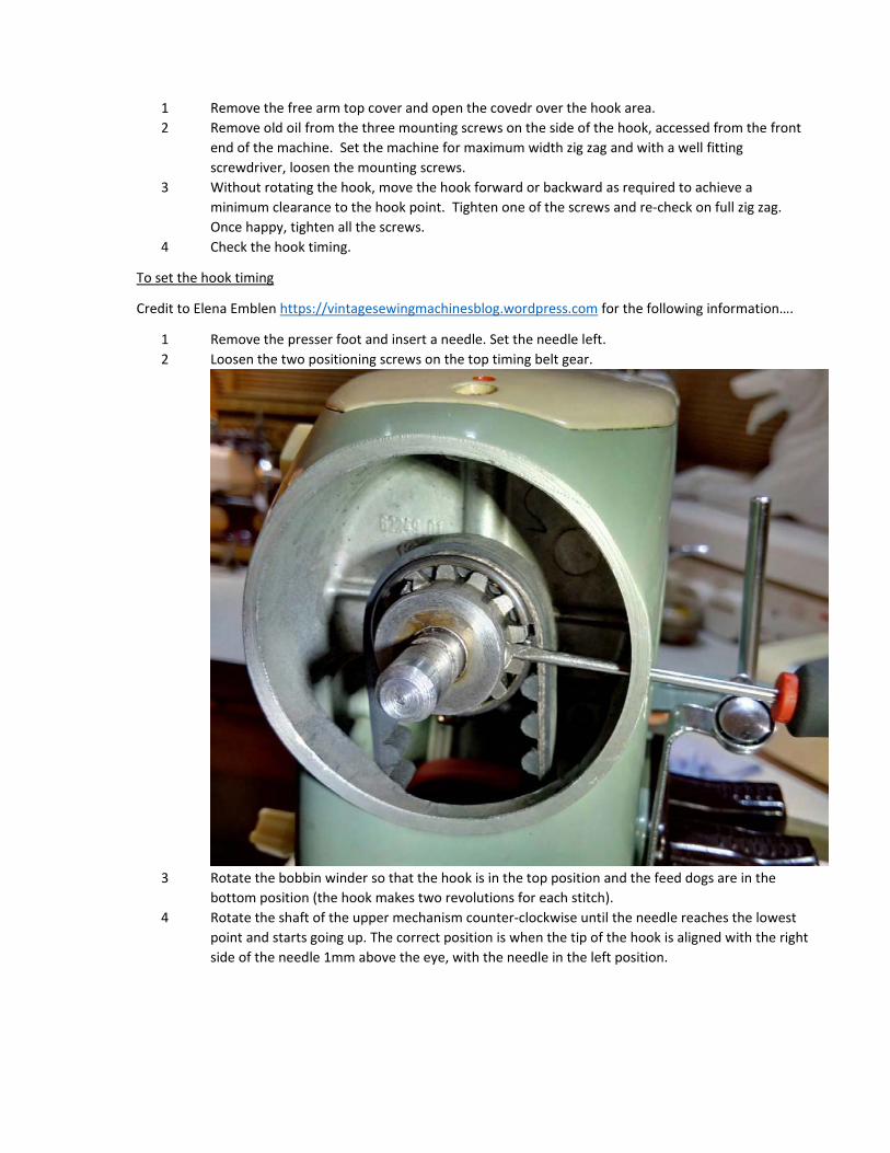
To set the hook timing
Credit to Elena Emblen https://vintagesewingmachinesblog.wordpress.com for the following information….
1 Remove the presser foot and insert a needle. Set the needle left.
2 Loosen the two positioning screws on the top timing belt gear.
3 Rotate the bobbin winder so that the hook is in the top position and the feed dogs are in the
bottom position (the hook makes two revolutions for each stitch).
4 Rotate the shaft of the upper mechanism counter‐clockwise until the needle reaches the lowest
point and starts going up. The correct position is when the tip of the hook is aligned with the right
side of the needle 1mm above the eye, with the needle in the left position.
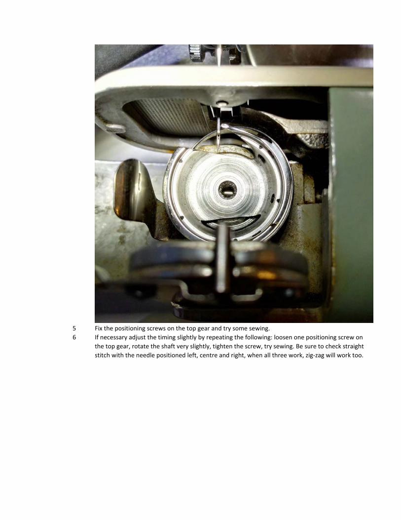
5 Fix the positioning screws on the top gear and try some sewing.
6 If necessary adjust the timing slightly by repeating the following: loosen one positioning screw on
the top gear, rotate the shaft very slightly, tighten the screw, try sewing. Be sure to check straight
stitch with the needle positioned left, centre and right, when all three work, zig‐zag will work too.
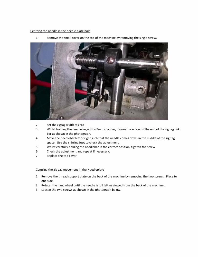
Centring the needle in the needle plate hole
1 Remove the small cover on the top of the machine by removing the single screw.
2 Set the zigzag width at zero
3 Whilst holding the needlebar,with a 7mm spanner, loosen the screw on the end of the zig zag link
bar as shown in the photograph.
4 Move the needlebar left or right such that the needle comes down in the middle of the zig zag
space. Use the shirring foot to check the adjustment.
5 Whilst carefully holding the needlebar in the correct position, tighten the screw.
6 Check the adjustment and repeat if necessary.
7 Replace the top cover.
Centring the zig zag movement in the Needleplate
1 Remove the thread support plate on the back of the machine by removing the two screws. Place to
one side.
2 Rotater the handwheel until the needle is full left as viewed from the back of the machine.
3 Loosen the two screws as shown in the photograph below.
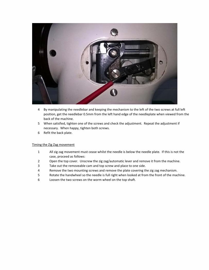
4 By manipulating the needlebar and keeping the mechanism to the left of the two screws at full left
position, get the needlebar 0.5mm from the left hand edge of the needleplate when viewed from the
back of the machine.
5 When satisfied, tighten one of the screws and check the adjustment. Repeat the adjustment if
necessary. When happy, tighten both screws.
6 Refit the back plate.
Timing the Zig Zag movement
1 All zig zag movement must cease whilst the needle is below the needle plate. If this is not the
case, proceed as follows:
2 Open the top cover. Unscrew the zig zag/automatic lever and remove it from the machine.
3 Take out the removeable cam and top screw and place to one side.
4 Remove the two mounting screws and remove the plate covering the zig zag mechanism.
5 Rotate the handwheel so the needle is full right when looked at from the front of the machine.
6 Loosen the two screws on the worm wheel on the top shaft.

7 Rotate the handwheel whilst preventing the wormwheel from rotating.
8 Tighten one of the screws and check the adjustment. Repeat the adjustment if necessary.
9 When happy, tighten both screws fully.
10 Replace the cover plate, cam and zig zag/auto lever.
11 Lower the top cover.
Components – Removal and Refitting
Bobbin case base ‐ removal and refitting
1 Rotate open the bobbin case cover. Remove the bobbin case if fitted.
2 Remove the free arm cover by firstly rotating the handwheel to raise the needle to the highest
point and removing the two allen key bolts. Place to one side.
3 Note the position of the bobbin case base positioning finger relative to the bobbin case base (see
photo). The mounting bolt fits in a slot – note the adjusted position so it can be refitted in the
same place.
4 Loosen the single bolt holding the bobbin case base retaining arm and lift the arm clear of the
bobbin case base. The bolt is relatively long so can be loosened a long way. The bolt is difficult to
replace if fully removed.
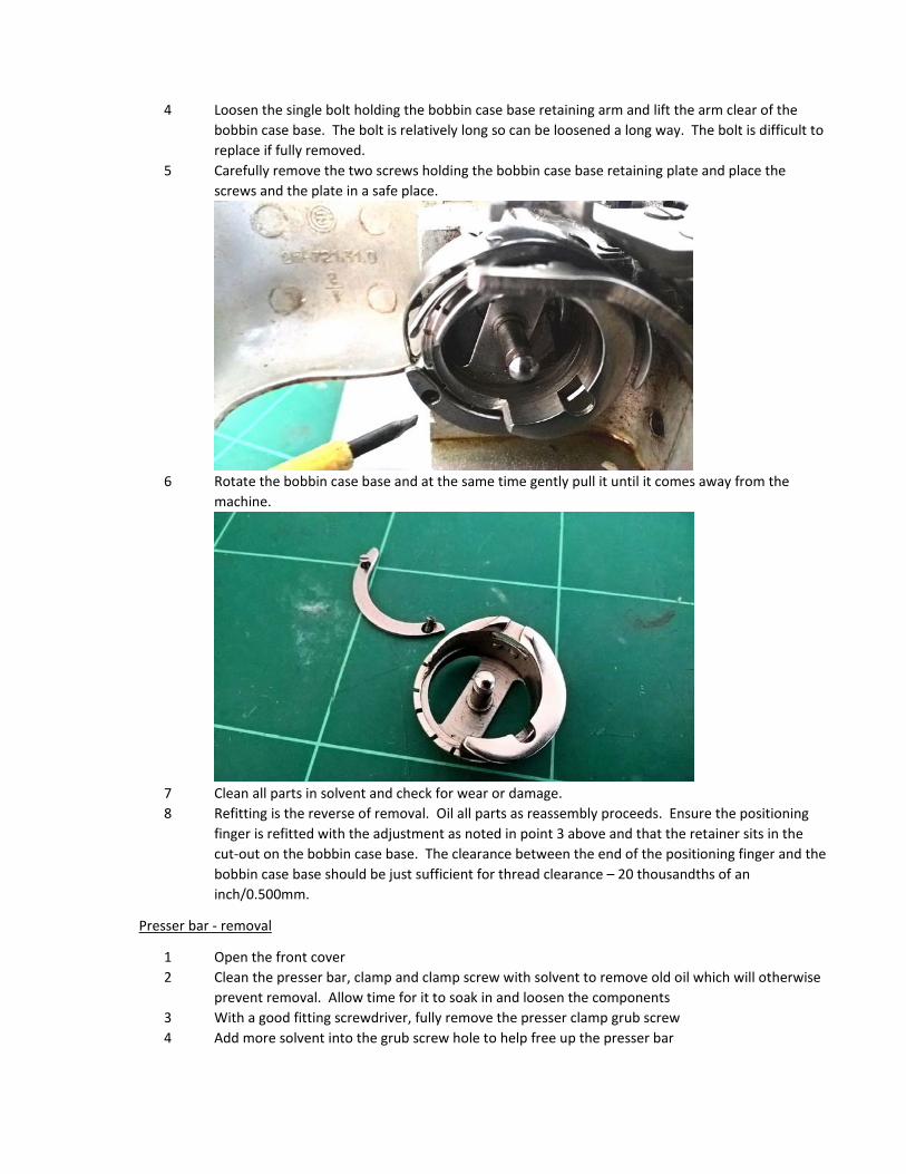
5 Carefully remove the two screws holding the bobbin case base retaining plate and place the
screws and the plate in a safe place.
6 Rotate the bobbin case base and at the same time gently pull it until it comes away from the
machine.
7 Clean all parts in solvent and check for wear or damage.
8 Refitting is the reverse of removal. Oil all parts as reassembly proceeds. Ensure the positioning
finger is refitted with the adjustment as noted in point 3 above and that the retainer sits in the
cut‐out on the bobbin case base. The clearance between the end of the positioning finger and the
bobbin case base should be just sufficient for thread clearance – 20 thousandths of an
inch/0.500mm.
Presser bar ‐ removal
1 Open the front cover
2 Clean the presser bar, clamp and clamp screw with solvent to remove old oil which will otherwise
prevent removal. Allow time for it to soak in and loosen the components
3 With a good fitting screwdriver, fully remove the presser clamp grub screw
4 Add more solvent into the grub screw hole to help free up the presser bar
5 Hold the presser foot and gently twist the presser bar until it comes free and is able to slide up
and down
6 Remove the presser foot and screw
7 Lift up and remove the presser bar from the machine, taking care to note the position of the
spring part way up the presser bar and remove it from the machine as the bar is removed.
8 Clean all components removed in solvent
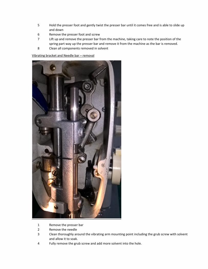
Vibrating bracket and Needle bar – removal
1 Remove the presser bar
2 Remove the needle
3 Clean thoroughly around the vibrating arm mounting point including the grub screw with solvent
and allow it to soak.
4 Fully remove the grub screw and add more solvent into the hole.

5 Insert a narrow screwdriver into the gap between the upper washer and the vibrating bracket and
gently twist it to loosen the pin. Fully remove the pin and washers.
6 Gently pull the vibrating bracket from the machine taking care not to stress the needle bar driving
mechanism.
7 Clean all components in solvent.
Needle bar ‐ removal
1 Note: it is not normally necessary to remove the needle bar to clean it. Removal will require the
needle bar height to be adjusted.
2 Remove the vibrating bracket and needle bar from the machine.
3 Loosen the mounting screw.
4 Slide the needle bar clamp along the needle bar and remove the needle bar from its mounting in
the vibrating bracket.
5 Clean all components in solvent.
Needle Bar, vibrating bracket and Presser bar – replacement
1 Replacement is the reverse of removal. Oil all components during reassembly and ensure the
spring is replaced on the presser bar as the presser bar is put back in the machine.
2 Adjust the presser bar height and alignment.
3 If the needle bar has been removed, adjust the needle bar height.
Machine base – removal and replacement
Follow sections 1‐7 of Motor removal and replacement.
Motor – removal and replacement
1 Remove the motor cover by removing the two retaining screws and place it to one side.
2 Place the machine on a soft surface and tip it onto its back.
3 Remove the three motor retaining bolts accessed from the bed of the machine.
4 Remove the four screws retaining the bed of the machine, taking care to support the body of the
machine once screws are removed.
5 Separate the bed from the body of the machine, taking care not to strain electrical wiring.
6 Remove the brackets holding the electrical components to the machine bed and separate the
electrical components from the bed.
7 Place the machine bed to one side.
8 Loosen the electrical connector block screws holding the electrical components and motor wiring.
9 Remove the motor and associated wiring and electrical components from the machine.
10 Refitting is the reverse of removal. Take care that electrical wiring is located clear of moving parts.
Electrical components – replacement
1 Remove the motor complete with components from the machine.

2 Loosen the screws on the mounting block and separate motor from components.
3 The wiring schematic for the machine is to be found under the removable plate under the
machine bed.
4 Obtain replacement electronic components to the specification outlined in the wiring schematic.
For late model UK spec machines the components are as follows:
Capacitors: 2 No. 2.2µf 250V DC aluminium electrolytic
1No. 22µf aluminium electrolytic, 250V DC
Inductor: 1No. 2x2.2mH common mode choke 100mΩ, 250V
5 Make up new soldered wiring set using new components and wires to the wiring schematic,
insulating the completed installation. It is important that the layout of components is similar to
the old layout in order to refit the components to the machine.
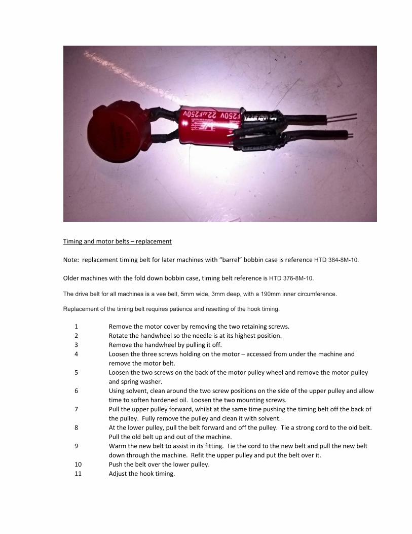
Timing and motor belts – replacement
Note: replacement timing belt for later machines with “barrel” bobbin case is reference HTD 384-8M-10.
Older machines with the fold down bobbin case, timing belt reference is HTD 376-8M-10. The drive belt for all machines is a vee belt, 5mm wide, 3mm deep, with a 190mm inner circumference. Replacement of the timing belt requires patience and resetting of the hook timing.
1 Remove the motor cover by removing the two retaining screws.
2 Rotate the handwheel so the needle is at its highest position.
3 Remove the handwheel by pulling it off.
4 Loosen the three screws holding on the motor – accessed from under the machine and
remove the motor belt.
5 Loosen the two screws on the back of the motor pulley wheel and remove the motor pulley
and spring washer.
6 Using solvent, clean around the two screw positions on the side of the upper pulley and allow
time to soften hardened oil. Loosen the two mounting screws.
7 Pull the upper pulley forward, whilst at the same time pushing the timing belt off the back of
the pulley. Fully remove the pulley and clean it with solvent.
8 At the lower pulley, pull the belt forward and off the pulley. Tie a strong cord to the old belt.
Pull the old belt up and out of the machine.
9 Warm the new belt to assist in its fitting. Tie the cord to the new belt and pull the new belt
down through the machine. Refit the upper pulley and put the belt over it.
10 Push the belt over the lower pulley.
11 Adjust the hook timing.
12 Refit the motor, motor belt and motor pulley. Tighten the motor mounting bolts sufficiently
for the motor belt to be just tight enough that it doesn’t slip under load.
13 Refit the motor cover.
Upper Tension Control – removal, dismantling, reassembly and adjustment
1 Dismantling of the upper tension control is best achieved with the mechanism removed from
the machine. To remove the whole upper tension assembly, open the front cover, loosen the
single grub screw and pull the mechanism away.
2 To dismantle the mechanism, first hold the body of the mechanism whilst pulling the tension
dial outward. At the same time as pulling out to bypass the limiting pin, rotate the dial
anticlockwise. Keep rotating and the mechanism will come apart. Carefully place the
components in the order they were removed to facilitate reassembly.
3 Clean all metal parts in solvent.
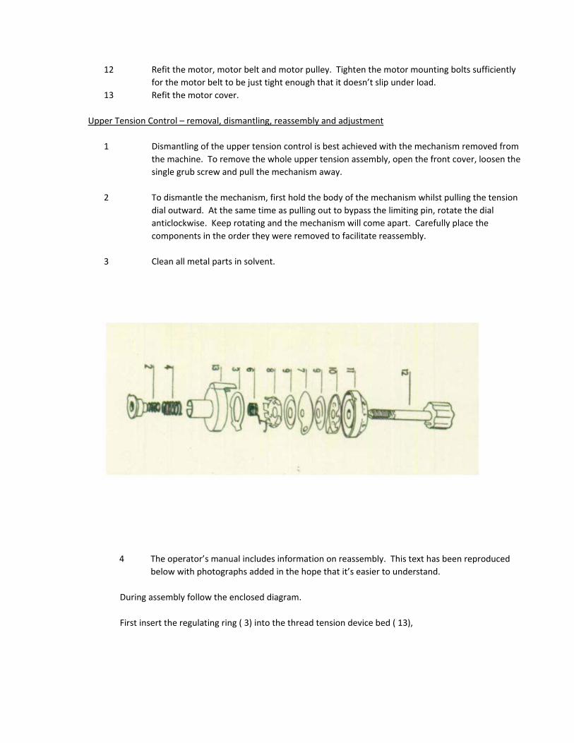
4 The operator’s manual includes information on reassembly. This text has been reproduced
below with photographs added in the hope that it’s easier to understand.
During assembly follow the enclosed diagram.
First insert the regulating ring ( 3) into the thread tension device bed ( 13),
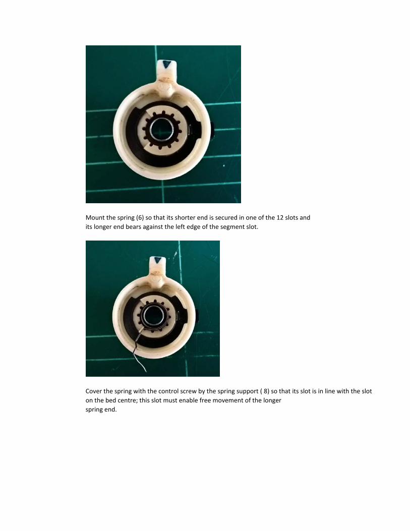
Mount the spring (6) so that its shorter end is secured in one of the 12 slots and
its longer end bears against the left edge of the segment slot.
Cover the spring with the control screw by the spring support ( 8) so that its slot is in line with the slot
on the bed centre; this slot must enable free movement of the longer
spring end.
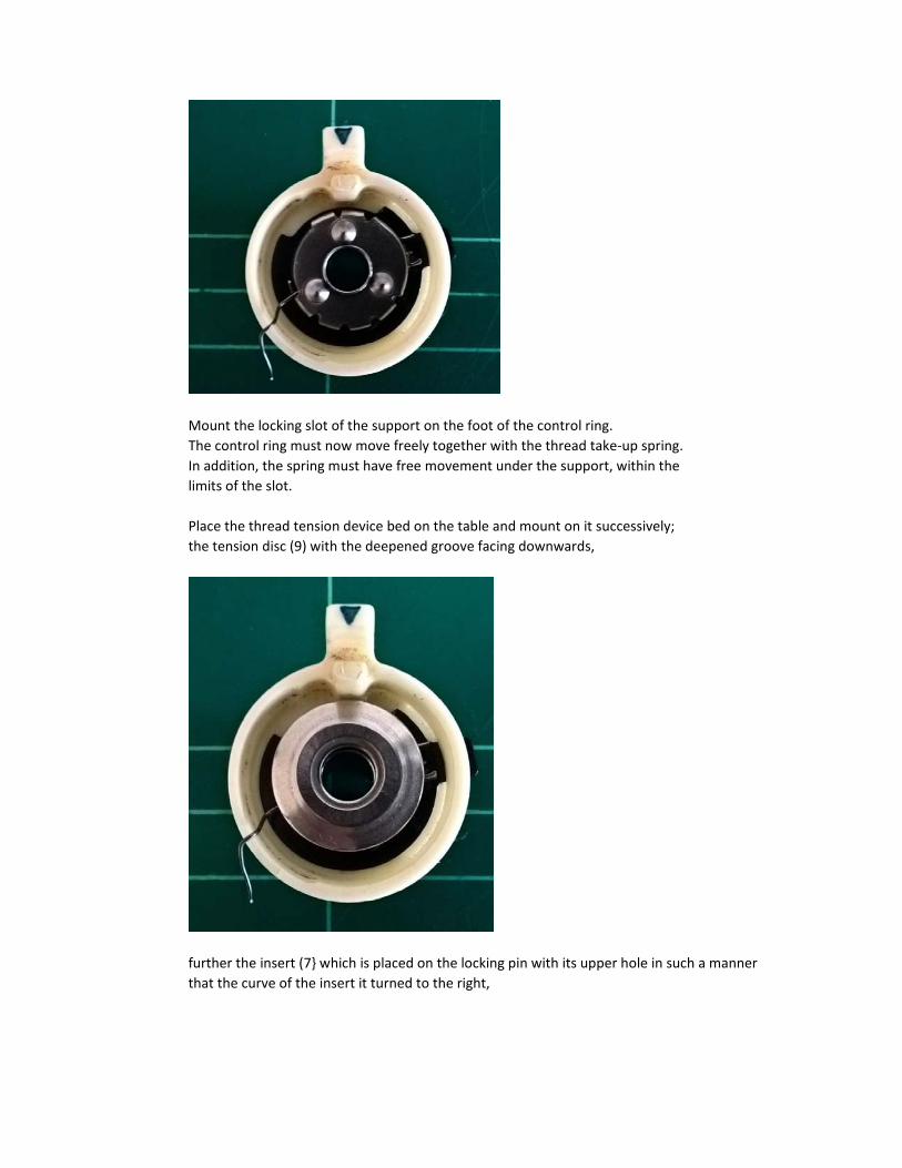
Mount the locking slot of the support on the foot of the control ring.
The control ring must now move freely together with the thread take‐up spring.
In addition, the spring must have free movement under the support, within the
limits of the slot.
Place the thread tension device bed on the table and mount on it successively;
the tension disc (9) with the deepened groove facing downwards,
further the insert (7 which is placed on the locking pin with its upper hole in such a manner
that the curve of the insert it turned to the right,
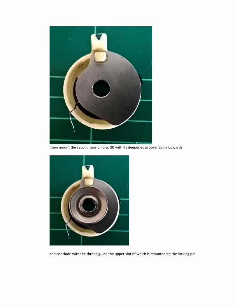
then mount the second tension disc (9) with its deepened groove facing upwards
and conclude with the thread guide the upper slot of which is mounted on the locking pin.

Slip the disc (11) on to the knob with pin (12) and pull the screw through all holes of
the combined parts.
Place two springs ( 2 and 4 on the bottom of the bed, mount the nut on the
end of the screw so that its slot fits into the groove of the pipe and screw in
the knob with the pin.
Finally check whether the bottom land of the nut matches the end of the bottom

of the bed when the knob is set to minimum.
To repair the thread Takeup spring
If the thread take‐up spring has been damaged by the external part being broken off, it may be possible to
repair it us follows:
1 Remove and disassemble the tension assembly
Examine the spring to see if it is salvageable. The coils of the spring need to be in line, with
sufficient coils remaining to modify the spring by straightening some of the coils.
2 Using a pair of round nosed pliars, or using protected pliars to prevent damage to the coils,
straighten out the end of the coil.
3 Using the pliars continue to bend the spring to produce a modified spring as the photograph:

4 Reassemble the tension mechanism. Trial and error with modification to the spring shape will be
needed to ensure the spring fits with no friction and operates satisfactorily.