t p r t. bergado, r manivannan and a.s. b r m · technical paper by d.t. bergado, r. manivannan and...
TRANSCRIPT

63G E O S Y N T H E TIC S IN T E R N ATIO N AL S 1996, V O L. 3, N O . 1
Technical Paper by D.T. Bergado, R. Manivannan andA.S. Balasubramaniam
FILTRATION CRITERIA FOR PREFABRICATEDVERTICAL DRAIN GEOTEXTILE FILTERJACKETS IN SOFT BANGKOK CLAY
ABSTRACT: Filtration tests on soil-geotextile filter systems were conducted in thelaboratory in order to evaluate the filtration and clogging performance of prefabricatedvertical drain (PVD)geotextile filter jackets in soft Bangkok clay. Initially, the flowwasvery slow for all types of PVD geotextile filter jackets and the soil permeability charac-teristics controlled the flow behavior. Subsequently, flow increasedwith time followedby a loss of fine particles. Finally, flow decreased and reached an equilibrium stage. Asa result of the laboratory filtration tests, filtration and clogging criteria are proposed forgeotextile filter jackets on PVDs in soft Bangkok clay.
KEYWORDS: Filtration, Clogging, Permeability, Soft clay, Prefabricated verticaldrain, Geotextile, Apparent opening size.
AUTHORS: D.T. Bergado, Associate Professor of Geotechnical Engineering, R.Manivannan, Graduate Student, and A.S. Balasubramaniam, Chair and Professor ofGeotechnical Engineering, School of Civil Engineering, Asian Institute of Technology,P.O. Box 2754, Bangkok 10501, Thailand, Telephone: 66/2-516-0110-29, Telefax:66/2-516-2126.
PUBLICATION: Geosynthetics International is published by the Industrial FabricsAssociation International, 345 Cedar St., Suite 800, St. Paul, Minnesota 55101, USA,Telephone: 1/612-222-2508, Telefax: 1/612-222-8215. Geosynthetics International isregistered under ISSN 1072-6349.
DATES: Original manuscript received 11 August 1995, revised version received 17January 1996 and accepted 22 January 1996. Discussion open until 1 September 1996.
REFERENCE: Bergado, D.T., Manivannan, R. and Balasubramaniam, A.S., 1996,“Filtration Criteria for Prefabricated Vertical Drain Geotextile Filter Jackets in SoftBangkok Clay”, Geosynthetics International, Vol. 3, No. 1, pp. 63-83.

BERGADO, MANIVANNAN & BALASUBRAMANIAM D Filtration Criteria for Vertical Drains
64 G E O S Y N T H E TIC S IN T E R N ATIO N AL S 1996, V O L. 3, N O . 1
1 INTRODUCTION
An effective prefabricated vertical drain (PVD) has two basic filtration functions:first to retain soil particles; and second, to allowwater to pass from the soil into the PVDcore. For PVDs, these two filtration functions are performed by a geotextile filter jacketwrapped around a drain core. For monolithic PVDs, on the other hand, filtration occursat the surface of the drain core, either by means of holes punched in the drain core, orby the natural permeability of the drain core material. In order to evaluate the filtrationand clogging performance of PVDs, filtration testswere conducted on various soil-geo-textile filter systems. Most of the results presented in this paper were derived from thework of Manivannan (1995).
2 PERMEABILITY
Hansbo (1979) proposed that the openings of a geotextile filter jacket should be fineenough to prevent soil particles from passing through. These fine soil particles cancause siltation and reduce the discharge capacity of the PVD (Hansbo 1981).Geotextilefilter jackets are quite thin, and even if they have a low permeability, the overall effecton the PVDperformance isminimal. This condition can be analyzed by considering thegeotextile filter jacket to be a smear zone of reduced permeability. Hansbo (1983) be-lieved that PVDgeotextile filter jackets used at that timewere too permeable to preventclogging and siltation of the drain core. The only situation in which a high permeabilitygeotextile filter jacket would be an advantage is the case where PVDs are installed invery deep deposits of claywith intermediate sand seamswhich would serve as horizon-tal drainage layers: a less permeable geotextile filter jacket in this situation may haveundesirable high head losses.In order for a geotextile to be considered an effective filter, it should not clog or blind
(Figure 1). Clogging can occur if soil particles move and become trapped within thefabric structure, reducing its permeability. Blinding occurs when soil particles are pre-vented from entering or passing through the geotextile and coat the geotextile surfaceforming a filter cake which can significantly reduce the permeability of the geotextile.A geotextile filter jacket may function as illustrated in Figure 2. A small amount of
particle movement occurs into or through the geotextile filter jacket leaving the coarser
Figure 1. Definition of clogging and blinding (after Bell and Hicks 1980).
Geotextilefilter
Blinding
Clogging by particle deposition

BERGADO, MANIVANNAN & BALASUBRAMANIAM D Filtration Criteria for Vertical Drains
65G E O S Y N T H E TIC S IN T E R N ATIO N AL S 1996, V O L. 3, N O . 1
Figure 2. How a geotextile filter jacket works (afterMcGown 1976; Bell and Hicks 1980).
Soil
Filter cake
Geotextile filter jacket
Soil bridge network
(Not to scale)
PVD core
particles to bridge and arch. The zone of fine particles immediately behind the soilbridge network is sometimes called a “filter cake”. Once the soil filter is established,no further particle movement will occur and the soil-geotextile jacket system is in equi-librium; hence, the geotextile filter jacket retains the soil and prevents itsmigration intothe drain core.While it may not actually filter the pore water, the geotextile filter jacketdoes act as a catalyst for the formation of a soil filter in the adjacent soil. The establish-ment of a stable and effective soil filter by the geotextile filter jacket depends on thefollowing (McGown 1976):
(1) The physical and mechanical properties of the geotextile filter jacket, e.g. pore sizeand pore size distribution, porosity, geotextile filter thickness, and compressibility.

BERGADO, MANIVANNAN & BALASUBRAMANIAM D Filtration Criteria for Vertical Drains
66 G E O S Y N T H E TIC S IN T E R N ATIO N AL S 1996, V O L. 3, N O . 1
(2) The characteristics of the soil to be protected, e.g. particle size and particle size dis-tribution, porosity, permeability, and cohesiveness.
(3) External stresses and strains imposed on the soil-PVD system, e.g. traffic and struc-tural loads.
(4) The prevailing hydraulic conditions, e.g. laminar or turbulent flow, unidirectionalor reversible flow, and dynamic or pulsating flow.
The first attempts to develop geotextile filter criteria were based on experience usinggraded granular filters. However, there are obvious problems in extending graded filtercriteria to geotextile filter design because the particle size distribution of the geotextilefilter is unknown. It ismore appropriate to consider the pore size distributionof the geo-textile filter, yet there is no simple method to measure it (Falyse et al. 1985; Chen andChen 1986). As with soils, the relationship between pore size distribution and perme-ability for geotextile filters is not yet established. It may be postulated that the perme-ability, clogging potential, and piping resistance of a geotextile filter depends on thetype of fibre, structure, and porosity.A high permeability for the geotextile filter jacket is desirable, but at the same time
loss of small soil particles through the geotextile filter jacket should be minimized. Themost important permeability criterion is that the geotextile filter must be and must re-main more permeable than the adjacent soil (Holtz and Christopher 1987). This criteri-on can be expressed as follows:
(1)kg ! ks
where: kg = permeability of the geotextile in the direction normal to the plane of thegeotextile; and, ks = permeability of the soil.For critical applications, Holtz and Christopher (1987) suggest that the permeability
of geotextile filters should be at least ten times the permeability of the soil. This geotex-tile filter hydraulic property is typically imposed during the selection phase. Ingold(1988) suggests that the designer has to forecast the long term performance to ensurethat the geotextile filter will fulfill its design function. Rollin and Lombard (1988) haveindicated that a geotextile filter may be partially clogged but still offer good perfor-mance. The work of Giroud (1982) suggests that the permeability of geotextile filterswith clogging taken into account need only be 10 times greater than the soil permeabil-ity.
3 SOIL RETENTION ABILITY
The performance of PVDs is strongly influenced by small soil particles that accumu-late within or near the geotextile filter jacket as a result of the flow of displaced porewater. An effective geotextile filter jacket should not allow too much soil to passthrough, otherwise piping may occur in the adjacent soil and the drainage path of thePVD core may become clogged, thereby decreasing its discharge capacity. Therefore,in selecting an appropriate geotextile for a geotextile filter jacket, the particle size dis-

BERGADO, MANIVANNAN & BALASUBRAMANIAM D Filtration Criteria for Vertical Drains
67G E O S Y N T H E TIC S IN T E R N ATIO N AL S 1996, V O L. 3, N O . 1
tribution of the soil should be considered. The geotextiles typically used for PVD filterjackets are nonwovens with nonuniform pore sizes.Current soil-geotextile filter system retention criteria are generally based on relation-
ships developed between a representative pore size of the geotextile and particle sizeof the soil. The parameters used for geotextile filter criteria proposed by many authorsare: characteristic soil particle sizes, e.g. D85 , D10 ; soil coefficient of uniformity, Cu =D60/D10 ; soil permeability, ks ; geotextile filter permeability, kg ; and, pore size charac-teristics of the geotextile filter, e.g. apparent opening size of the geotextile filter (AOS).According to Kellner et al. (1983), several factors should be considered when eva-
luating the retention ability of geotextile filter jackets: chemical properties of the geo-textile fibers; and soil composition. Several empirical relationshipshave beenproposedto simplify geotextile filter selection and these criteria are presented in Table 1.
Table 1. Summary of filtration criteria for geotextile filters.
Source Criterion Remarks
Bergado et al. (1992)
Ogink (1975)
Carroll (1983)
Christopher and Holtz(1985)
Holtz and Christopher(1987)
Calhoun (1972)
Chen and Chen (1986)
Sweetland (1977)
Rankilor (1981)
O90/D85 " 2 to 3O50/D50 " 18 to 24
O90/D90 " 1.8
O95/D85 " 2 to 3
O95 " 1.8 D85Steady stateAOS < 0.3 D85
For steady stateO95 " 0.5, D85 " 0.3 mmFor dynamic flowO50 " 0.5 D85
O95/D85 " 1
O90/D85 " 1.2 to 1.8O50/D50 " 10 to 12
O15/D85 " 1O15/D85 " 1
O50/D85 " 1O50/D50 " 25 to 37O15/D15 " 1
Nonwovens, clay recommended
Nonwovens, type of soil not specified
For both wovens and nonwovens, type of soilnot specified
Nonwovens, for soils with greater than 50%particles passing the 75 mm sieve
Nonwovens, for silts and clay
Suitable for geotextile filters with a high per-centage of large pores
Nonwovens, soils with Cu = 1.5Nonwovens, soils with Cu = 4
Nonwovens, soils with 0.02 " D85 < 0.25 mmNonwovens, cohesive soilNonwovens, soils with D85 > 0.25 mm
Notes: O95 ,O90 ,O50 ,O15 = geotextile filter opening size such that 95, 90, 50 and 15%, respectively, of poresare smaller than that size;D85 ,D50 ,D15 = soil particle diameter such that 85, 50 and 15%, respectively, of thesoil particles, are smaller than that diameter.

BERGADO, MANIVANNAN & BALASUBRAMANIAM D Filtration Criteria for Vertical Drains
68 G E O S Y N T H E TIC S IN T E R N ATIO N AL S 1996, V O L. 3, N O . 1
4 CLOGGING RESISTANCE
The criteria for geotextile filter jacket clogging resistance depend on project critical-ity and the severity of the hydraulic loading conditions. Selection of a geotextile filterjacket for critical applications and severe conditions should be based on: the soil reten-tion and permeability criteria for critical situations. In addition the geotextile must alsosatisfy clogging criteria for less critical applications and soil-geotextile filtration testsshould be performed using representative samples of site soils.The suggested filtration test for soils with ks > 10-7 m/s (silts, clayey and silty sands)
is the gradient ratio test and the recommended gradient ratio (GR) criterion is GR < 3(Carroll 1983;Holtz 1986). For finer grained soilswith ks <10-7 m/s, long term filtrationtests should be performed. It should be emphasized that the gradient ratio test is not yetfully standardized and that considerable experience is required to obtain reproducibleresults (Christopher and Holtz 1985).A geotextile filter jacket clogs and its permeability reduces if soil particles become
trapped within the geotextile fabric structure. Therefore, it is recommended that fornonwoven geotextile filter jackets, with a porosity greater than 30%, placed in a poten-tial clogging environment, such as gap graded and silty soils, a porosity qualifier shouldbe included (Holtz 1986). Optional porosity qualifiers are selected based on experiencewith the use of granular piles, and ensure that finer soil particles can pass through thegeotextile filter jacket without clogging it. For example:
(2)O95 # 3 D15 and O15 # 2 D15 to 3 D15
5 FILTRATION MECHANISMS
The permeability and pore size distribution of geotextile filter materials are selectedto restrain particle migration while allowing water to pass through their structure. Thelong term performance of these geotextile filters can be affected by soil conditions, de-sign of the filtration system, installation procedures and hydraulic conditions. It is im-portant to understand that in order to perform its filtration function adequately, the geo-textile filter must act as a barrier suitable to the formation of a natural filter by one of,or a combination of, the following mechanisms: auto filtration; blocking of particlesat the filter surface; or, vault network formation (Rollin and Lombard 1988).Vreeken et al. (1983) performed filtration experiments to investigate the retention ca-
pability of geotextile filters and the effect of suspended soil particles on geotextile filterresistance. Itwas found that the retention capability and clogging resistance of a geotex-tile filter are mainly dependent on the pore size distribution of the geotextile filter. Theprincipal geotextile filter mechanisms can be distinguished as follows: (i) cake filtra-tion; (ii) deep filtration; and (iii) blocking filtration.Cake filtration occurswhen the soil particles are larger than the geotextile filter pores.
All particles are retained on the geotextile filter and the resistance of the filter cake towater flow increases. In the case of pure infiltration and an incompressible filter cake,there is a linear relationship between the amount of retained particles and the resistanceto flow through the filter cake. Rollin and Lombard (1988) and Williams and Abou-

BERGADO, MANIVANNAN & BALASUBRAMANIAM D Filtration Criteria for Vertical Drains
69G E O S Y N T H E TIC S IN T E R N ATIO N AL S 1996, V O L. 3, N O . 1
zakhm (1989) have indicated that the flow across the soil-geotextile filter system inter-face triggers the formationof a filter cake due to themigrationof fine soil particles. Thisfilter cake, or transitional filter, typically impedes water flow.Blocking filtration, on the other hand, occurs when the particles have roughly the
same diameter as the pores of the geotextile filter. The particles are retained in the geo-textile filter and filter flow resistance can rise rapidly. If the pore size distribution ofthe geotextile filter is large, only the larger pores may become blocked after a cake isformed.Deep filtration occurs when the particles are smaller than the geotextile filter pores
and the particles adhere to the geotextile filter. When filtration begins, the geotextilefilter resistance increases, and, as a result of the increasing pressure drop across the fil-ter, the particles are detached and the geotextile filter resistance decreases.
6 LABORATORY TESTS
Ten different PVDswere tested. The product names and designations used in the cur-rent study are shown in Table 2. All PVD products had a geotextile filter jacket withthe exception of Desol which is a monolithic PVD comprising a one piece plasticcore.
6.1 Apparent Opening Size (AOS)
The method used to determine the AOS of a geotextile utilizes glass beads sievedthrough a geotextile following the ASTM D 4751 standard. The AOS indicates theapproximate largest particle size that would effectively pass through the geotextile.A mechanical sieve shaker was used to impart a vertical and lateral motion to the
sieve, causing the particles to bounce and turn so as to present different orientations tothe geotextile surface. Spherical glass beads were used in the appropriate size fractionto match the range of the geotextiles tested. Static eliminators were used to prevent theaccumulation of static electricitywhen the beadswere shaken on the surface of the geo-textile.
6.2 Filtration Test
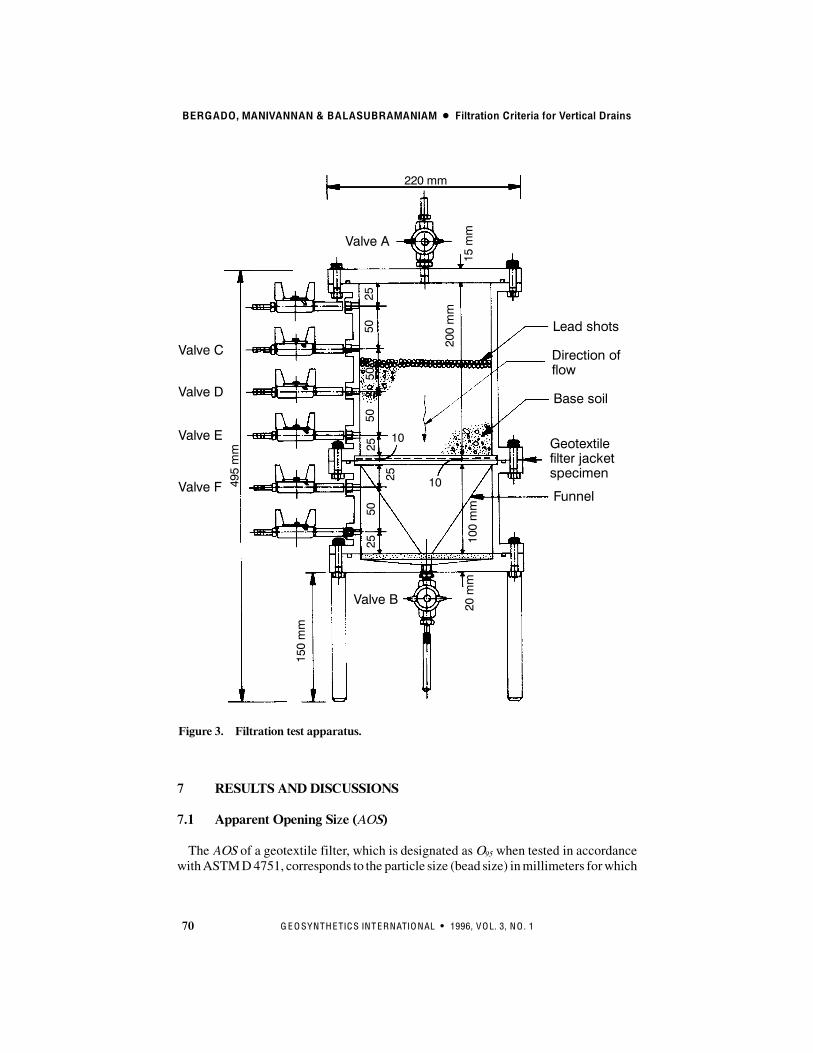
The filtration test apparatus used in the study consists of a 310 mm high lucite cylin-der with a 150mm internal diameter as shown in Figure 3. The cylinder can be detachedinto two portions and a geotextile which acts as a filter can be placed between the twosections of the cylinder. A valve was installed at the bottom of the cylinder to regulatethe water flow. Before running a test, the geotextile filter specimen was saturated andthen placed between the two sections of the cylinder. A thoroughly mixed clay wasplaced to a thickness of 100 mm over the geotextile filter jacket specimen. The valveswere opened and water was allowed to flow through the soil and geotextile filter jacketspecimen under constant head. The volume of water leaving the apparatus was mea-sured with time.
BERGADO, MANIVANNAN & BALASUBRAMANIAM D Filtration Criteria for Vertical Drains
70 G E O S Y N T H E TIC S IN T E R N ATIO N AL S 1996, V O L. 3, N O . 1
Figure 3. Filtration test apparatus.
Valve C
Valve D
Valve E
Valve F
Valve B
Funnel
Geotextilefilter jacketspecimen
Base soil
Direction offlow
Lead shots
Valve A495mm
150mm
20mm
100mm
220 mm
15mm
5050
5025
25
25
25
10
10
200mm
50
7 RESULTS AND DISCUSSIONS
7.1 Apparent Opening Size (AOS)
The AOS of a geotextile filter, which is designated asO95 when tested in accordancewithASTMD4751, corresponds to the particle size (bead size) inmillimeters forwhich

BERGADO, MANIVANNAN & BALASUBRAMANIAM D Filtration Criteria for Vertical Drains
71G E O S Y N T H E TIC S IN T E R N ATIO N AL S 1996, V O L. 3, N O . 1
5% or less by mass passes through the geotextile. The AOS value does not represent areliable indicator of geotextile filter permeability or clogging resistance. The results oftheAOS tests are given inTable 2. The selected geotextile filter jackets differ inmaterialcomposition and in the method used to strengthen the geotextile.The AOS method has limitations in measuring small pore sizes due to electrostatic
forces and any surface coatingon the geotextile. The build-up of static electricity causesthe glass beads to cling to the geotextile rather than pass through, leading to erroneousresults. Static eliminators added to the sieve frame walls reduce or eliminate the build-up of static electricity. In some instances, the geotextile manufacturing process leavesa surface coating on the geotextile which may clog some of the geotextile openingswhich also lead to erroneous test results. The use of AOS for nonwoven geotextiles (themost common geotextile filter jacket for PVDs) has been criticized (Holtz and Chris-topher 1985). It is impractical to specify an AOS smaller than 0.075 mmbecause it can-not be measured using the ASTM D 4751 standard test method.Among the PVD geotextile filter jackets tested, PVD Fwith one geotextile layer (old
design) gave the highestAOS of 0.6mm.However, when PVDFwith two layers of geo-textile (improved design) was tested it gave anAOS of 0.075 mm. The PVDD and PVDH geotextile filter jackets gave AOS values less than 0.075 mm. Figure 4 presents thepore size distribution of the PVD geotextile filter jackets and the particle size distribu-tion of the clay used in the current study.
Table 2. Apparent opening size (AOS) results.
PVD type AOS (mm)
Name Designation Manufacturer’s data Laboratory test results
Alidrain A 0.12 0.160
Amerdrain 408 B 0.16 0.200
Castleboard CS C 0.074 0.075
Colbond CX-1000 D < 0.075 < 0.075
Desol * E 0.20 N/A
Fibredrain F Not provided 0.60 (one layer), 0.075 (two layer)
Flodrain FD4-EX G < 0.090 0.075
Geodrain “L” H Not provided < 0.075
Hongplast GD-75 I < 0.075 0.075
Mebradrain MD-7007 J 0.075 0.075
Notes: * Monolithic one piece core without geotextile filter jacket. N/A = not applicable.

BERGADO, MANIVANNAN & BALASUBRAMANIAM D Filtration Criteria for Vertical Drains
72 G E O S Y N T H E TIC S IN T E R N ATIO N AL S 1996, V O L. 3, N O . 1
Figure 4. Particle size distribution of the Bangkok clay at two different depths and theresults of apparent opening size (O95) standard tests (ASTMD 4751) of three different PVDgeotextile filter jackets.
100
80
60
40
20
0
Particle size (mm)1 0.1 0.01 0.001
Clay depth 9 mClay depth 2 mPVD APVD BPVD F
Percentpassing
7.2 Filtration Test Results
Filtration test results for the soil-geotextile filter jacket systems are plotted in Figures5, 6 and 7. As shown in these figures, the flow rate (m3/year) was computed per squaremeter surface area using a hydraulic gradient, i = 1. Immediately after the installationof the geotextile filter, the initial flow rate for all systems was very slow. This indicatesthat initial flow behavior is dominated by the hydraulic properties of the soil, while thelong time flowbehavior is dominated by the hydraulic properties of the geotextile filter(Lawson1982). Figures5, 6 and 7 show that the flowrate across the soil-geotextile filtersystem then decreases with time, indicating movement of fine particles towards thegeotextile filter and initial clogging of the geotextile filter openings. Once the fine par-ticles adjacent to the geotextile filter were removed in the filtration process, an increasein the flow rate was observed. The subsequent retention of soil particles on the geotex-tile filter led to cake formation, resulting in a reduction of flow rate until an equilibriumcondition was reached.As shown in Figure 5, the flow rate for the PVDA geotextile filter jacket did not be-
come stable even after it decreased from a peak flow rate. Afterwards, the flow rate forthe PVDA geotextile filter jacket increased due to loss of fine particles which indicatesthat soil-geotextile filter system equilibrium was not reached. Similarly, for the PVDF geotextile filter jacket (one geotextile filter layer) the flow decreased initially and in-creased suddenly to a high value. The fine soil particles lost during this increment of

BERGADO, MANIVANNAN & BALASUBRAMANIAM D Filtration Criteria for Vertical Drains
73G E O S Y N T H E TIC S IN T E R N ATIO N AL S 1996, V O L. 3, N O . 1
Figure 5. Variation of flow rate with time for PVD geotextile filter jackets from filtrationtests.
Figure 6. Variation of flow rate with time for PVD geotextile filter jackets from filtrationtests.
PVD A
PVD I
i = 1.0
32
600
400
200
00 2000 4000 6000 8000
Time (minutes)
Legend:
a = soil loss phaseb = cake build-upphase
a b
PVD BPVD DPVD H
a b
a b
i = 1.0
200
0
100
300
0 2000 4000 6000Time (minutes)
Legend:
a = soil loss phaseb = cake build-upphase
PVD F (one geotextile layer)
Flowrate(m/yr/m)
32
Flowrate(m/yr/m)
Regression analysis

BERGADO, MANIVANNAN & BALASUBRAMANIAM D Filtration Criteria for Vertical Drains
74 G E O S Y N T H E TIC S IN T E R N ATIO N AL S 1996, V O L. 3, N O . 1
Figure 7. Variation of flow rate with time for PVD geotextile filter jackets from filtrationtests.
PVD C
a bi = 1.0
0
100
0 2000 4000 6000Time (minutes)
8000
50
150
PVD GPVD J
a b
Legend:
a = soil loss phase
b = cake build-upphase3
2Flowrate(m/yr/m)
Regression analysis
flow for the PVD F geotextile filter jacket was also very high due to its large pore sizes(Figure 4). Thus, when using a geotextile filter jacket with relatively large pore sizes,such as the PVD F geotextile filter jacket, a large amount of soil can be deposited inthe PVD core leading to the obstruction of its flow channels and clogging. The PVDI geotextile filter jacket, on the other hand, did not show a significant change in flowrate with time.For the PVDBgeotextile filter jacket (Figure 6), the flow rate was erratic for approxi-
mately 4000minutesbefore it reached a quasi-stable flowstate. This could be attributedto the loss of fine particles or internal rearrangement of soil particles. The flow rate forthe PVDD geotextile filter jacket increased significantly for approximately 3750min-utes becoming stable after the loss of fine particles. For the PVDHgeotextile filter jack-et, there was a slight increase in flow rate after approximately 1200 minutes which re-mained stable until the end of the test.Figure 7 shows that the flowrate for the PVDCgeotextile filter jacket did not increase
significantly during the early stages of the test. After the specimen reached a peak flowrate, the flow rate decreased abruptly and then remained steady until the end of the test.The flow rate for the PVD G geotextile filter jacket increased abruptly reaching peakflow at approximately 3000 minutes and then decreased suddenly and became stablewith time. During the early stages of testing, the flow rate for the PVD J geotextile filterjacket remained constant, then increased abruptly at 1300 minutes, and then decreasedslightly and remained steady until the end of the test.

BERGADO, MANIVANNAN & BALASUBRAMANIAM D Filtration Criteria for Vertical Drains
75G E O S Y N T H E TIC S IN T E R N ATIO N AL S 1996, V O L. 3, N O . 1
Among the geotextile filter jackets tested, PVD I, H and C exhibited the lowest flowrates (Figures 5, 6 and 7). The flow in these geotextile filters did not change significant-ly with time unlike the other geotextile filters, which reached peak flow, decreased forsome time, and then became stable.When the design criteria (Table 3) are applied to the PVD A geotextile filter jacket
(Figure 5) they indicate that its pore size distribution is course and that it cannot preventsoil loss and subsequent clogging of the PVD core. A similar conclusion is reached forthe PVD B geotextile filter jacket since the scattered points (Figure 6) indicate that thevariation in flow rate was caused by soil loss. The large pore sizes of the PVDBgeotex-tile filter jacket prevented the flowrate from reaching an equilibrium condition quickly.Therefore, the results of filtration tests on the PVD A and B geotextile filter jacketsdemonstrate that the geotextile filter jacket pore size must be able to prevent the lossof fine particles.For the PVD C geotextile filter jacket (Figure 7), the flow rate reached equilibrium
after the fine soil particles were removed. However, it took quite some time to increasethe flow rate through the PVD D geotextile filter jacket (Figure 6). In the case of thePVDH geotextile filter jacket (Figure 6), the flow rate was initially negligible and thensuddenly increased unlike the gradual increase in flow rate of the other PVD geotextilefilter jackets. The flow rate were varied and did not show any regular behavior. Thismay be due to pore size changes during the test period. It should be noted that the PVDHgeotextile filter jacket is very thin compared to the other PVDgeotextile filter jackets.The flow rate for the PVD J geotextile filter jacket, on the other hand, became stablevery rapidly, at approximately 2600 minutes.
Table 3. Relationship between pore size ofPVD geotextile filter jackets and soil particle size.
Source CriterionPVD designation
Source CriterionA B F G J
Bergado et al.(1992)
O90/D85 " 2 - 3O50/D50 " 18 - 24
4.7 - 17.526.7 - 80
5.3 - 2033.3 - 100
20 - 46.213.3 - 44
2 - 7.516.7 - 50
2.5 - 9.4
Ogink(1975) O90/D90 " 1.8 2.8 - 15.6 3.2 - 17.8 12 - 66.7 1.2 - 6.7 1.5 - 8.3
Carroll(1983) O95/D85 " 2 - 3 5.33 - 20 6.67 - 25 20 -75 2.3 - 8.75 2.5 - 9.4
Rankilor(1981) O50/D50 " 25 - 37 26.7 - 80 33.3 - 100 20 - 75 16.7 - 50 --
ChristopherandHoltz (1985)
O95 " 1.8 D85Steady StateAOS " 0.3 D85
5.33 - 20 6.67 - 25 20 - 75 2.3 - 8.75 2.5 - 9.4
Holtz andChristopher(1987)
Steady StateO95 " 0.5 D85 " 0.3 mm 5.33 - 20 6.67 - 25 20 - 75 2.3 - 8.75 2.5 - 9.4
Calhoun(1972) O95/D85 " 1 5.33 - 20 6.67 - 25 20 - 75 2 3 - 8.75 2.5 - 9.4
Chen and Chen(1986)
O90/D85 " 1.2 - 1.8O50/D50 " 10 - 12
4.7 - 17.526.7 - 80
6.67 - 2533.3 - 100
20 - 46.2133.3 - 400
2 - 7.516.7 - 50
2.5 - 9.4--

BERGADO, MANIVANNAN & BALASUBRAMANIAM D Filtration Criteria for Vertical Drains
76 G E O S Y N T H E TIC S IN T E R N ATIO N AL S 1996, V O L. 3, N O . 1
8 SPECIFICATIONS
8.1 Filtration
It can be observed that as the filtration time increased, the permeability of the soil-geotextile filter systems decreased. The general trend is that in the initial time periodof approximately 15 to 30 hours (900 to 1800minutes), the flow increases, thengradual-ly decreases, and finally reaches a constant value.Based on the analyses of all the tests performed, three types of filtration behavior can
be identified:
S Type I, cake build-up and soil stabilization;S Type II, continuous loss of soil particles; andS Type III, cake build-up with the loss of few soil particles and soil stabilization.
It was also found that geotextiles can act as effective filters as long as their filtrationbehavior is of Types I and III. The change in the interface layer of the soil-geotextilefilter systems can be summarized by the occurrence of the following five mechanisms:migration of soil particles; loss of soil particles; cake build-up; trapping of soil particleswithin the geotextile filter; and soil stabilization.It is very difficult to determine the contribution of clogging to the reduction in flow
rate from the filtration tests because the flow rate is initially controlled by the hydraulicproperties of the soil, not by the soil-geotextile filter system. Moreover, it takes timeto reach equilibrium conditions. In order for a geotextile filter jacket to be effective,it must prevent soil particles from moving towards the PVD core and flow rate mustreach equilibrium. The PVD J geotextile filter jacket had a very small amount of soilparticle loss and reached an equilibrium condition quickly, indicating a good soil-geo-textile filter system. The PVDF geotextile filter jacket (one layer geotextile filter jack-et), quickly reached a quasi-stable flow condition, but the loss of soil particles contin-ued which could eventually clog the PVD core. A flow reduction factor can be definedthat is the ratio of the steady state flow rate to the peak flow rate. The flow reductionfactors for the PVD B, C, D, F, G, I and J geotextile filter jackets are 4.0, 1.7, 3.3, 3.0,6.8, 2.0 and 1.3, respectively.Koerner and Ko (1982) have performed long term filtration tests on soil-geotextile
filter systems and obtained flow reduction factors in the range of 2.84 to 4.2. The resultsindicated that the soil-geotextile filter systems reached equilibrium after 100 hours.Rao et al. (1994) also performed long term filtration tests for soil-nonwoven geotextilefilter systems. The flow reduction factors which they obtained varied from 2.5 to 6.7with the largest values due to increasing soil fines content. In their tests it took 150 to300 hours to reach equilibrium using a slurry soil. Thus, the flow reduction factor dueto filtration and clogging is thought to be in the range of 1.3 to 6.75, with an averagevalue of 3.5.Various filtration criteria have been checked against the data obtained for the pore
size distribution of the geotextile filter jacket and the particle sizes of Bangkok clay(Figure 4). Table 3 includes the relationships between the soil particle size and the poresize distribution of the PVD A, B, F, G, and J geotextile filter jackets.
BERGADO, MANIVANNAN & BALASUBRAMANIAM D Filtration Criteria for Vertical Drains
77G E O S Y N T H E TIC S IN T E R N ATIO N AL S 1996, V O L. 3, N O . 1
For PVD A, all of the filtration criteria indicate that the pore sizes of the geotextilefilter jacket are large and it cannot prevent soil loss. Figure 5 indicates that the PVDAgeotextile filter jacket experienced a large loss of fine soil particles and that it did notreach equilibrium conditions quickly. The PVDBgeotextile filter jacket exhibited sim-ilar behavior and the scattered points in Figure 6 indicate flow rate variation due to soilloss. The PVDBgeotextile filter jacket pore sizes are large (Figure 4), and thus equilib-rium conditions could not be reached quickly.The PVD F geotextile filter jacket gave higher values for all of the filtration criteria,
including a high loss of soil particles, whichmay lead to clogging of the PVD core. Thefiltration test, clearly indicated that a large amount of fine particleswere removed. Poresize distribution and filtration test results for PVD A, B and F geotextile filter jacketsindicate that the loss of fine soil particles increases with increasing pore size distribu-tion.The filtration test results for PVD G and J geotextile filter jackets indicate that flow
rates became stable quickly even though some fine soil particles were lost. The dataobtained from these PVD geotextile filter jackets are close to values recommended byBergado et al. (1992), Carrol (1983) and Calhoun (1972).TheD85 of Bangkok clay varies from 0.030 mm to 0.008 mm depending on the depth
of soil. If the aforementioned criteria are used forBangkok clay, theAOSmust bewithinthe range of 0.024mm to 0.090mm; however, it is very difficult to find geotextile filtershaving an AOS less than 0.024 mm. This criterion is somewhat conservative when con-sidering that Bangkok clay is cohesive and that the concentration of fine particles in theclay increases with depth. Thus, the AOS should not be larger than 0.090 mm. Usinga maximum D85 value of 0.03 mm, and a O95 (AOS) value of 0.090 mm, the geotextilefilter and soil should have aO95/D85 value less than or equal to 3.0 in order to satisfy thisretention criterion.
8.2 Permeability
There are various expressions for filtration criteria for granular filters. Typical classi-cal expressions for the permeability and retention criteria of granular filters, respective-ly, are as follows:
(3)D15(filter) ! 5 D15(soil)
D15(filter) $ 5 D85(soil) (4)
The permeability of a granular filtermaterial with a uniform particle size distributionis proportional to the square of the diameter of the particles. When the particle size dis-tribution is not uniform, classical theory assumes that the permeability is proportionalto D2
10 or D215 .
AssumingDarcy flowperpendicular to the surface of the granular filter, the followingequations can be written:
S Flow rate per unit area with a granular filter;

BERGADO, MANIVANNAN & BALASUBRAMANIAM D Filtration Criteria for Vertical Drains
78 G E O S Y N T H E TIC S IN T E R N ATIO N AL S 1996, V O L. 3, N O . 1
(5)Q%A & h%'df%kf ( ds%ks)
S Flow rate per unit area without granular filter;
(6)Q*%A & hks%ds
where: h = hydraulic head; ds , df = soil and granular filter thickness; and ks , kf = perme-ability of the soil and granular filter.Hence:
(7)Q%Q* & 1%'+dfks, ( +df%kf, ( 1)
In order tominimize the flowdisturbance caused by the granular filter, (df)(ks)/(ds)(kf)must be less than 1. In geotechnical engineering practice, a disturbance is usually con-sidered negligible when the value of (df)(ks)/(ds)(kf) is less than 0.1. Furthermore, a fac-tor of safety of 10 is recommended in the above calculation to compensate for the vari-ability in soil permeability values. The above criterion can be stated as follows:
(8)+dfks,%+ds%kf, $ 0.01
A df value of approximately 1m and a ds value of 10m can be used for granular filters.Thus, for granular filters:
(9)kf ! ks
Therefore, the permeability of a granular filter must be 10 times larger than the perme-ability of the soil. A similar recommendation is made by Giroud (1982) and Holtz andChristopher (1987) in the case of a soil-geotextile filter system.In the case of a geotextile filter, the df value can be taken as 1 mm and a typical value
for soil thickness, ds , can be taken as 0.50m. Therefore, Equation 9becomes the follow-ing for a geotextile filter:
(10)kg ! 0.2 ks
Vreeken et al. (1983) showed that the permeability of PVD geotextile filter jacketsdecreases by a factor of 4 to 5, either from clogging or from the formation of a filtercake. In Malaysia, a geotextile filter was excavated six years after installation andpermeability tests were conducted to determine its long term performance (Loke et al.1994). The test results indicated that the ratio of original permeability to the permeabil-ity of the exhumed geotextile varied from 1.7 to 3.3. In this case, while trimming thesoil samples, sand lenses and pocketswere observed indicating that horizontal drainage

BERGADO, MANIVANNAN & BALASUBRAMANIAM D Filtration Criteria for Vertical Drains
79G E O S Y N T H E TIC S IN T E R N ATIO N AL S 1996, V O L. 3, N O . 1
layerswere present. Therefore, geotextile filter jackets should have a higher permeabil-ity than the surrounding clay. The factor of safety against clogging can be taken as 5and an additional safety factor of 2 can be used to account for the possible presence ofhorizontal permeable (drainage) layers such as sand lenses and silt seams within theclay. The permeability criterion can then be expressed as:
(11)kg ! 2 ks
Therefore, the permeability of geotextiles used as filters must be at least two timesgreater than the permeability of the soil.
8.3 Clogging Criteria
Clogging, which reduces the permeability of the geotextile filter jacket, is caused byfine particles penetrating into the geotextile filter jacket which were previously block-ing the soil pore channels, or were caked on the upstream side of the geotextile filterjacket. Bangkok clay satisfies the clogging criterion expressed as O95 (AOS)# n D15 ,where n varies depending on the particle size distribution. Holtz et al. (1995) suggestsan n value of three. Due to the small size of the Bangkok clay particles and the largepore sizes of the geotextile filter jacket, the ratio ofO95/D15 is very high. The definitionof clogging is closely related to the permeability criterion given in Equation 11 that isused to minimize clogging. Considering that permeability is proportional to D2
10 or D215
when the particle size distribution is not uniform, the clogging criterion can be ex-pressed as O15/D15 # 1.5.
9 CONCLUSIONS
Based on a literature review and analyses of laboratory test results on geotextiles usedfor filter jackets on PVDs in Bankok clay, the following conclusions are presented:
(1) Based on the average flow reduction factors obtained from the filtration tests thatranged from 1.3 to 6.75, the flow reduction value due to filtration and clogging canbe taken as 3.5.
(2) The permeability of a geotextile filter jacket should be more than two times thepermeability of the soil, i.e. kg # 2 ks . Taking D85 = 0.03, which is the maximumvalue of D85 for Bangkok clay (varies from 0.030 to 0.008 mm) and O95 (AOS) =0.090 mm, the ratioO95/D85 " 3.0 for the geotextile filter jacket and the soil is rec-ommended to satisfy the soil retention function.
(3) Considering that the D85 of Bangkok clay varies from 0.030 mm to 0.008 mm, theapparent opening size, O95 (AOS), of the PVD geotextile filter jacket should not begreater than 0.090 mm when the AOS of the geotextile is determined in accordancewith ASTM D 4751 in order to satisfy the soil retention function.
(4) The definition of clogging is closely related to the permeability criterion of kg > 2 ksand, considering that the permeability is proportional to D2
10or D215when the particle
BERGADO, MANIVANNAN & BALASUBRAMANIAM D Filtration Criteria for Vertical Drains
80 G E O S Y N T H E TIC S IN T E R N ATIO N AL S 1996, V O L. 3, N O . 1
size distribution is not uniform, the geotextile filter jacket should satisfyO15/D15 #1.5 to prevent clogging.
REFERENCES
ASTM D 4751, “Standard Testing Method for Determining Apparent Opening Size ofaGeotextile”, American Society for Testing andMaterials, Philadelphia, Pennsylva-nia, USA.
Bell, J.R. andHicks, R.G., 1980, “Evaluation of TestMethodsandUseCriteria forGeo-technical Fabrics in Highway Applications - Interim Report”, U.S. Department ofTransportation, Federal Highway Administration, Report No. FHWA/RD-80/021,Washington, DC, USA, June 1980, 190 p.
Bergado, D.T., Alfaro,M.C. andChan, E.H.C., 1992, “Filtration and Drainage Charac-teristics of Vertical Drain”, Proceedings of a Symposium on International LowlandTechnology, Institute of Lowland Technology, Saga, Japan, pp. 181-188.
Calhoun, C.C., 1972, “Development of Design Criteria and Acceptance Specificationsfor Plastic Cloth”, Technical Report S-72-7, U.S. Army Corps of Engineers, Water-ways Experiment Station, Vicksburg, Mississippi, USA, 105 p.
Carroll, R.G., Jr., 1983, “Geotextile Filter Criteria”, Transportation Research Record916, Washington, DC, USA, pp. 46-53.
Chen, R.H. andChen, C.N., 1986, “Permeability Characteristics of PrefabricatedVerti-cal Drains”, Proceedings of the Third International Conference on Geotextiles, Vol.1, Vienna, Austria, April 1986, pp 46-53.
Christopher, B.R. and Holtz, R.D., 1985, “Geotextile Engineering Manual”, U.S. De-partment of Transportation, Federal Highway Administration, Washington, DC,USA, Report No. FHWA-TS-86/203, March 1985, 1044 p.
Falyse, E., Rollin, A.R., Rigo, J.M. and Gourc, J.P., 1985, “Study of the Different Tech-niques Used to Determine the Filtration Opening of Geotextiles”, Proceedings of theSecond Canadian Symposium onGeotextiles andGeomembranes, Edmonton, Alber-ta, Canada, September 1985, pp. 45-50.
Giroud, J.P., 1982, “Filter Criteria for Geotextiles”,Proceedings of the Second Interna-tional Conference on Geotextiles, IFAI, Vol. 1, Las Vegas, Nevada, USA, August1982, pp. 103-108.
Hansbo, S., 1979, “Consolidation of Clay by Band Shaped Prefabricated Drains”,Ground Engineering, Vol. 12, No. 5, pp. 21-25.
Hansbo, S., 1981, “Consolidation of Fine Grained Soils by Prefabricated Drains”, Pro-ceedings of the Tenth International Conference on Soil Mechanics and FoundationEngineering, Vol. 3, Stockholm, Sweden, pp. 677-682.
Hansbo, S., 1983, “How to Evaluate the Properties of Prefabricated Drains”, Proceed-ings of the Eighth European Conference on Soil Mechanics and Foundation Engi-neering, Vol. 2, Helsinki, Finland, pp. 621-626.
Holtz, R.D., 1986, “Use of EngineeringFabrics in Transportation”, Update of the Fed-eral Highway Administration Instruction Manual.
BERGADO, MANIVANNAN & BALASUBRAMANIAM D Filtration Criteria for Vertical Drains
81G E O S Y N T H E TIC S IN T E R N ATIO N AL S 1996, V O L. 3, N O . 1
Holtz, R.D. and Christopher, B.R., 1987, “Characteristics of Prefabricated Drains forAccelerating Consolidation”, Proceedings of the Ninth EuropeanConference on SoilMechanics and Foundation Engineering, Balkema, Vol. 2, Dublin, Ireland, August1987, pp. 903-906.
Holtz, R.D., Christopher, B.R. and Berg, R.R., 1995, “Geosynthetic Design andConstruction Guidelines”, Participant Notebook, NHI Course No. 13213, NationalHighway Institute, FHWA, U.S. Department of Transportation, Washington, D.C.,USA.
Kellner, L., Bally, R.T. andMatter, S., 1983, “Some Aspects Concerning RetainingCa-pacity of Geotextiles”, Proceedings of the Second International Conference on Geo-textiles, IFAI, Vol. 1, Las Vegas, Nevada, USA, August 1982, pp. 85-90.
Ingold, T.S., 1988, “Civil Engineering Requirements for Long-Term Behavior of Geo-textiles”, Durability of Geotextiles, RILEM, Chapman and Hall, London, UnitedKingdom, Proceedings of a seminar held in St. Rémy-les-Chevreuse, France, No-vember 1986, pp. 20-29.
Koerner, R.M. and Ko, F.K., 1982, “Laboratory Studies on Long-term Drainage Capa-bility of Geotextiles”, Proceedings of the Second International Conference on Geo-textiles, IFAI, Vol. 1, Las Vegas, Nevada, USA, August 1982, pp. 91-95.
Lawson, C.R., 1982, “Filter Criteria for Geotextiles: Relevance and Use”, Journal ofGeotechnical Engineering, ASCE, Vol. 108, No. GT 10, 1300-1317.
Loke, K.H., Lee, C.H., Lim, C.H. and Chin, P.W., 1994, “Performance of NonwovenGeotextile in Coastal Protection Works in Marine Clays”, Proceedings of the FifthInternational Conference on Geotextiles, Geomembranes and Related Products, Vol.2, Singapore, September 1994, pp. 647-650.
Manivannan,R., 1995, “SystematicReview andProposal for SpecificationsCriteria forPrefabricated Vertical Drain (PVD) on Soft Bangkok Clay”, Master of EngineeringThesis, No. GT-94-27, Asian Institute of Technology, Bangkok, Thailand, 196 p.
McGown, A., 1976, “The Properties and Uses of Permeable Fabric Membranes”, Pro-ceedings of the Workshop on Materials and Methods for Low Cost Road, Rail andReclamation Works, Lee, Ingles and Yeaman, Eds., published by the University ofNew South Wales, Leura, Australia, September 1976, pp. 663-710.
Ogink, H.J.M., 1975, “Investigations on the Hydraulic Characteristics of SyntheticFabrics”, Delft Hydraulics Laboratory, PublicationNo. 146, Delft, TheNetherlands.
Rankilor, P.R., 1981, “Membranes in Ground Engineering”, John Wiley, Chichester,United Kingdom, 377 p.
Rao, G.V., Gupta, K.K. and Pradhan, M.P.S., 1994, “Long Term Filtration Behavior ofSoil Geotextile Systems”,Geotechnical Testing Journal, Vol. 15, No. 3, pp. 238-247.
Rollin, A.L. and Lombard, G., 1988, “MechanismsAffectingLong-Term FiltrationBe-havior of Geotextiles”, Geotextiles and Geomembranes, Vol. 7, Nos. 1 and 2, pp.119-145.
Sweetland, D.B., 1977, “The Performance of Non-woven Fabrics as Drainage Screensin Subdrains”, M.Sc. Thesis, University of Strathclyde, Glasgow, United Kingdom,207 p.

BERGADO, MANIVANNAN & BALASUBRAMANIAM D Filtration Criteria for Vertical Drains
82 G E O S Y N T H E TIC S IN T E R N ATIO N AL S 1996, V O L. 3, N O . 1
Vreeken, C., van den Berg, F. and Loxham, M., 1983, “The Effect of Clay-Drain Inter-face Erosion on the Performance of Band Shaped Vertical Drains”, Proceedings ofthe Eighth European Conference on Soil Mechanics and Foundation Engineering,Vol. 2, Helsinki, Finland, May 1983, pp. 713-716.
Williams, N.D. andAbouzakhm, M.A., 1989, “Evaluation of Geotextile/Soil FiltrationCharacteristics Using the Hydraulic Conductivity Ratio Analysis”, Geotextiles andGeomembranes, Vol. 8, No. 1, pp. 1-26.
NOTATIONS
Basic SI units are given in parentheses.
A = area perpendicular to the flow direction (m2)Cu = soil coefficient of uniformity (dimensionless)D10 = diameter such that 10% of the soil particles by mass are smaller than that
diameter (m)D15 = diameter such that 15% of the soil particles by mass are smaller than that
diameter (m)D15(filter) = diameter such that 15% of the soil particles by mass in a “granular filter”
are smaller than that diameter (m)D15(soil) = diameter such that 15% of the soil particles by mass (for a soil-granular
filter system) are smaller than that diameter (m)D50 = diameter such that 50% of the soil particles by mass are smaller than that
diameter (m)D85 = diameter such that 85% of the soil particles by mass are smaller than that
diameter (m)D85(soil) = diameter such that 85% of the soil particles by mass (for a soil-granular
filter system) are smaller than that diameter (m)D90 = diameter such that 90% of the soil particles by mass are smaller than that
diameter (m)df = thickness of filter layer (m)ds = thickness of soil layer (m)h = hydraulic head (m)i = hydraulic gradient (dimensionless)k = permeability (m/s)kf = permeability of granular filter (m/s)kg = permeability of geotextile filter normal to the plane of the geotextile
(m/s)ks = permeability of soil (m/s)O15 = geotextile opening size such that 15% of pores are smaller than that size
(m)

BERGADO, MANIVANNAN & BALASUBRAMANIAM D Filtration Criteria for Vertical Drains
83G E O S Y N T H E TIC S IN T E R N ATIO N AL S 1996, V O L. 3, N O . 1
O50 = geotextile opening size such that 50% of pores are smaller than that size(m)
O85 = geotextile opening size such that 85% of pores are smaller than that size(m)
O90 = geotextile opening size such that 90% of pores are smaller than that size(m)
O95 = geotextile opening size such that 95% of pores are smaller than that size(m)
Q = flow rate through a granular filter and a soil layer (m3/s)Qi = flow rate through a soil layer (m3/s)