t-engine hardware specification - tron
TRANSCRIPT
TEF010-S001-01.01.02/en 1
T-Engine Hardware Specification Ver. 1.01.02
TEF010-S001-01.01.02/en
May 2008
T-Engine Hardware Specification/Ver. 1.01.02
TEF010-S001-01.01.02/en 2
Table of Contents
1. Overview of T-Engine ........................................................................................................................................... 4
1.1 What is T-Engine? ........................................................................................................................................... 4
1.2 Entire Configuration of T-Engine System....................................................................................................... 4
1.3 Scope of Application of Specification ............................................................................................................. 5
2. Basic Configuration of CPU Board ....................................................................................................................... 6
3. Implementation Specifications of CPU Board....................................................................................................... 8
3.1 Implementation Specifications of CPU Board A side ..................................................................................... 8
3.2 Implementation Specifications of CPU Board B side...................................................................................... 9
4. Interface Specifications of CPU Board................................................................................................................ 10
4.1 Expansion Bus Interface Specification .......................................................................................................... 10
4.2 Serial Interface Specification......................................................................................................................... 11
4.3 PC Card Interface Specification .................................................................................................................... 12
4.4 LCD/Touch Panel Interface Specification..................................................................................................... 12
4.5 eTRON SIM Card Interface Specification..................................................................................................... 13
4.6 Interface Specifications of USB Host ............................................................................................................ 15
4.7 Audio Input/output Interface Specification ................................................................................................... 15
4.8 Power supply Interface Specification ............................................................................................................ 16
5. Specifications for Power Control Function of T-Engine Hardware..................................................................... 17
5.1 System States and their Names...................................................................................................................... 17
5.2 Specifications for External Power Supply Control Function......................................................................... 17
5.3 Functions to handle power blackout .............................................................................................................. 18
6. Regulation and Operation of T-Engine Hardware ............................................................................................... 19
6.1 About T-Engine Logo Marking ..................................................................................................................... 19
6.2 Documentation............................................................................................................................................... 19
6.3 Accreditation Standard of T-Engine Hardware ............................................................................................. 20
7. Expansion Board Standard .................................................................................................................................. 21
7.1 Size of Expansion Board Plate ...................................................................................................................... 21
7.2 Restricted Area for Expansion Board Implementation .................................................................................. 22
7.3 Stacking Specification for the Expansion Board ........................................................................................... 22
T-Engine Hardware Specification/Ver. 1.01.02
TEF010-S001-01.01.02/en 3
Update history
Version Date Content of update 01.01.01 2005.7 First Edited 01.01.02 2008.5 -Change the model name of recommended parts for expansion bus
connector, PC card connector, USB connector, and eTRON connector to RoHs-compliant parts. -Change the model name of recommended parts for serial connector and audio input/output connector. -Added comments to the recommended interface for LCD/touch panel. -Add 16-pin connector to serial connector specification.
T-Engine Hardware Specification/Ver. 1.01.02
TEF010-S001-01.01.02/en 4
1. Overview of T-Engine
1.1 What is T-Engine?
(1) Features
Open platform for real-time system of next generation and ubiquitous system CPU agnostic Common physical form factor, and common interface T-Kernel real-time OS support
(2) Applied Target for T-Engine
As a reference development platform for portable information equipments (such as PDA, e-book, and next-generation cellular phone), Internet information terminal, SetTopBox, controller for information appliances, and in-vehicle information terminal, etc.
As a training board for hardware and real-time programming As a general-purpose control board
(3) Merits of T-Engine Application
Allows dramatic shortening of development period due to accumulation and distribution of middleware, and distribution of peripheral Expansion board.
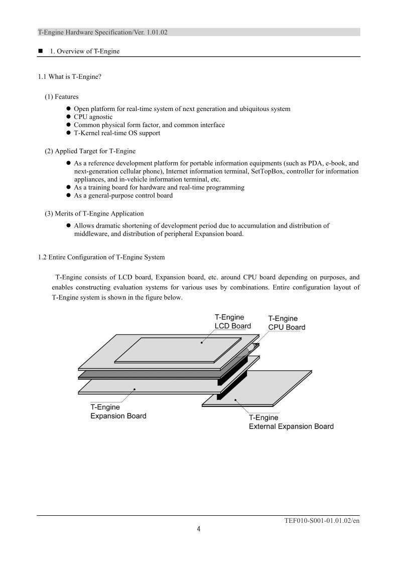
1.2 Entire Configuration of T-Engine System
T-Engine consists of LCD board, Expansion board, etc. around CPU board depending on purposes, and enables constructing evaluation systems for various uses by combinations. Entire configuration layout of T-Engine system is shown in the figure below.
T-Engine Hardware Specification/Ver. 1.01.02
TEF010-S001-01.01.02/en 5
(1) CPU Board The CPU board is the standard board that allows stand-alone operation. It consists of 32bit CPU, memory,
RTC, power supply control function, etc. It also has various interfaces such as serial port, PC Card, Audio CODEC, USB Host, eTRON card, LCD, expansion bus connector, etc. on the board.
(2)LCD Board LCD board consists of display devices for PDA, electronic book, cellular-phone and others, and any
user input device such as touch panel, key input and others.
(3) Expansion Board Consists of network functions such as Ethernet, Bluetooth, and IEEE1394 plus various extended
functions such as extended memory and mass-storage devices.
(4) Debug Board Consists of debugging function for debug board such as JTAG interface and writing function to flash
memory of a CPU board.
1.3 Scope of Application of Specification
These specifications shall apply to regulations of the following specifications.
(1)CPU board specifications Physical form factor specification and electronic specification regarding CPU board
(2) Expansion Board Physical form factor specification and electronic specification regarding Expansion board
(3)Documentation Regulations for documents on T-Engine hardware
T-Engine Hardware Specification/Ver. 1.01.02
TEF010-S001-01.01.02/en 6
2. Basic Configuration of CPU Board
(1) CPU Basic structure: Built-in MMU (Memory Management Unit), 32bit or more CPU
(2) RAM Appropriate volume of storage
(3) Flash memory Appropriate volume of storage
(4) eTRON SIM card interface SIM card connector interface (3.3V) that complies with ISO7816 mounted 1 Slot: (UICC SIM Card connector mounted) Complies with ETSI TS102221 V4.1.0
(5) LCD/Touch Panel Interface 1ch mounted (any touch panel is acceptable)
(6) Real-time clock (RTC) Must be equipped with 1ch calendar (Backup with battery or high-volume capacitor is recommended.)
(7) PC Card Interface
Complies with PCMCIA Standard Release 2.1/JEIDA 4.2
TYPE II/I Slot x 1 mounted
Compliance with CardBus is optional
(Refer to: http://www.pcmcia.org/pccardstandard.htm#1)
(8) USB Host Interface
Complies with USB Specification Rev1.1 Series "A" receptacle x 1 mounted
(9) Serial Port Interface Asynchronous serial communication port (by dedicated cable connection) 1ch: 115.2kbps or faster
T-Engine Hardware Specification/Ver. 1.01.02
TEF010-S001-01.01.02/en 7
(10) Switch The following functions are equipped with minimum rate of 3bits • Turn on/off power • NMI • Reset
(11) Audio Input/output Interface Stereo headphone output: 1ch Headset input/output: earphone: 1ch, microphone: 1ch
(12) Expansion Bus Interface Dedicated connector for T-Engine standard extended bus 1 slot (140-pin) Must comply with "Expansion bus connector Common Specifications"
(13) Power connector (DC jack) Connector complies with EIAJ RC-5320A
T-Engine Hardware Specification/Ver. 1.01.02
TEF010-S001-01.01.02/en 8
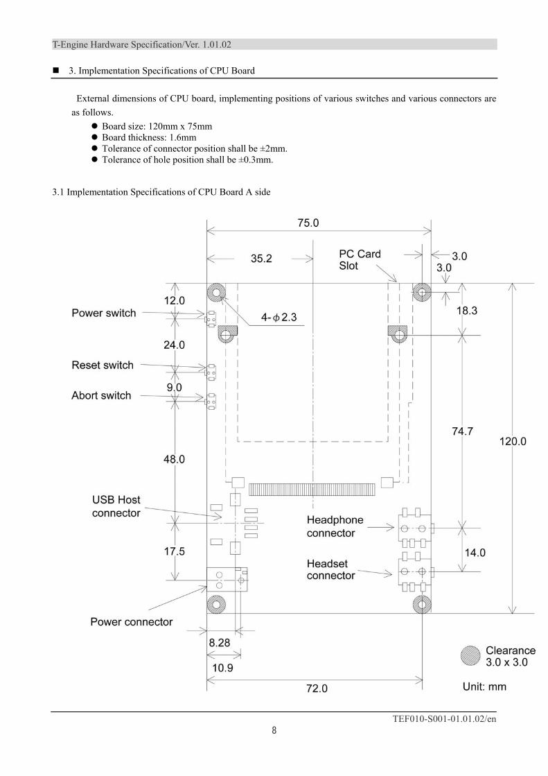
3. Implementation Specifications of CPU Board
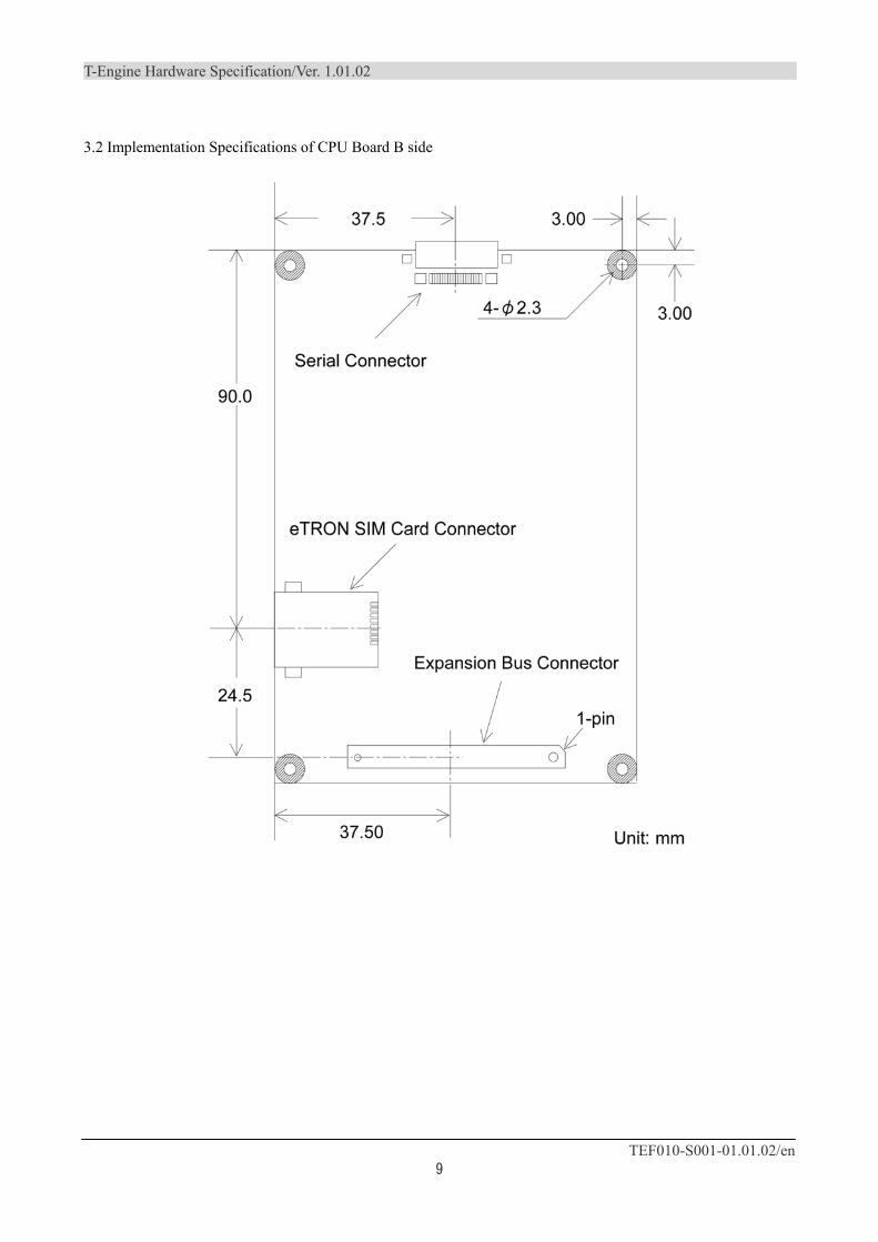
External dimensions of CPU board, implementing positions of various switches and various connectors are as follows.
Board size: 120mm x 75mm Board thickness: 1.6mm Tolerance of connector position shall be ±2mm. Tolerance of hole position shall be ±0.3mm.
3.1 Implementation Specifications of CPU Board A side
T-Engine Hardware Specification/Ver. 1.01.02
TEF010-S001-01.01.02/en 9
3.2 Implementation Specifications of CPU Board B side
T-Engine Hardware Specification/Ver. 1.01.02
TEF010-S001-01.01.02/en 10
4. Interface Specifications of CPU Board
4.1 Expansion Bus Interface Specification
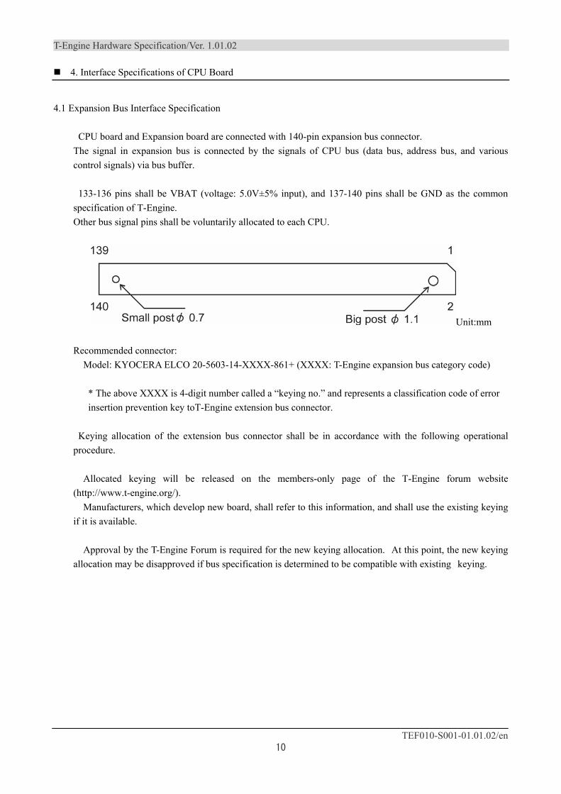
CPU board and Expansion board are connected with 140-pin expansion bus connector. The signal in expansion bus is connected by the signals of CPU bus (data bus, address bus, and various control signals) via bus buffer.
133-136 pins shall be VBAT (voltage: 5.0V±5% input), and 137-140 pins shall be GND as the common specification of T-Engine. Other bus signal pins shall be voluntarily allocated to each CPU.
Unit:mm
Recommended connector: Model: KYOCERA ELCO 20-5603-14-XXXX-861+ (XXXX: T-Engine expansion bus category code)
* The above XXXX is 4-digit number called a “keying no.” and represents a classification code of error insertion prevention key toT-Engine extension bus connector.
Keying allocation of the extension bus connector shall be in accordance with the following operational procedure.
Allocated keying will be released on the members-only page of the T-Engine forum website (http://www.t-engine.org/).
Manufacturers, which develop new board, shall refer to this information, and shall use the existing keying if it is available.
Approval by the T-Engine Forum is required for the new keying allocation. At this point, the new keying
allocation may be disapproved if bus specification is determined to be compatible with existing keying.
T-Engine Hardware Specification/Ver. 1.01.02
TEF010-S001-01.01.02/en 11
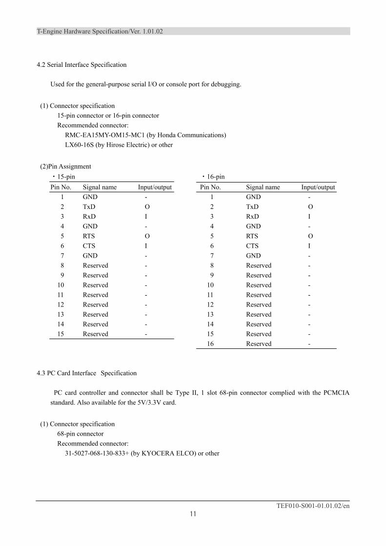
4.2 Serial Interface Specification Used for the general-purpose serial I/O or console port for debugging.
(1) Connector specification 15-pin connector or 16-pin connector Recommended connector:
RMC-EA15MY-OM15-MC1 (by Honda Communications) LX60-16S (by Hirose Electric) or other
(2)Pin Assignment ・15-pin
Pin No. Signal name Input/output 1 GND - 2 TxD O 3 RxD I 4 GND - 5 RTS O 6 CTS I 7 GND - 8 Reserved - 9 Reserved -
10 Reserved - 11 Reserved - 12 Reserved - 13 Reserved - 14 Reserved - 15 Reserved -
・16-pin Pin No. Signal name Input/output
1 GND - 2 TxD O 3 RxD I 4 GND - 5 RTS O 6 CTS I 7 GND - 8 Reserved - 9 Reserved -
10 Reserved - 11 Reserved - 12 Reserved - 13 Reserved - 14 Reserved - 15 Reserved - 16 Reserved -
4.3 PC Card Interface Specification
PC card controller and connector shall be Type II, 1 slot 68-pin connector complied with the PCMCIA
standard. Also available for the 5V/3.3V card.
(1) Connector specification 68-pin connector Recommended connector:
31-5027-068-130-833+ (by KYOCERA ELCO) or other
T-Engine Hardware Specification / Ver. 1.01.02
TEF010-S001-01.01.02/en 12
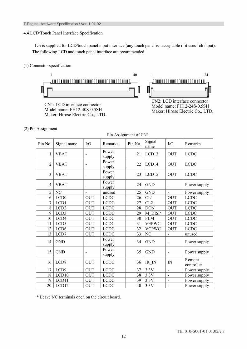
4.4 LCD/Touch Panel Interface Specification
1ch is supplied for LCD/touch panel input interface (any touch panel is acceptable if it uses 1ch input). The following LCD and touch panel interface are recommended.
(1) Connector specification
(2) Pin Assignment
Pin Assignment of CN1
Pin No. Signal name I/O Remarks Pin No. Signal name I/O Remarks
1 VBAT - Power supply 21 LCD13 OUT LCDC
2 VBAT - Power supply 22 LCD14 OUT LCDC
3 VBAT - Power supply 23 LCD15 OUT LCDC
4 VBAT - Power supply 24 GND - Power supply
5 NC - unused 25 GND - Power supply 6 LCD0 OUT LCDC 26 CL1 OUT LCDC 7 LCD1 OUT LCDC 27 CL2 OUT LCDC 8 LCD2 OUT LCDC 28 DON OUT LCDC 9 LCD3 OUT LCDC 29 M_DISP OUT LCDC
10 LCD4 OUT LCDC 30 FLM OUT LCDC 11 LCD5 OUT LCDC 31 VEPWC OUT LCDC 12 LCD6 OUT LCDC 32 VCPWC OUT LCDC 13 LCD7 OUT LCDC 33 NC - unused
14 GND - Power supply 34 GND - Power supply
15 GND - Power supply 35 GND - Power supply
16 LCD8 OUT LCDC 36 IR_IN IN Remote controller
17 LCD9 OUT LCDC 37 3.3V - Power supply 18 LCD10 OUT LCDC 38 3.3V - Power supply 19 LCD11 OUT LCDC 39 3.3V - Power supply 20 LCD12 OUT LCDC 40 3.3V - Power supply
* Leave NC terminals open on the circuit board.
T-Engine Hardware Specification/Ver. 1.01.02
TEF010-S001-01.01.02/en 13
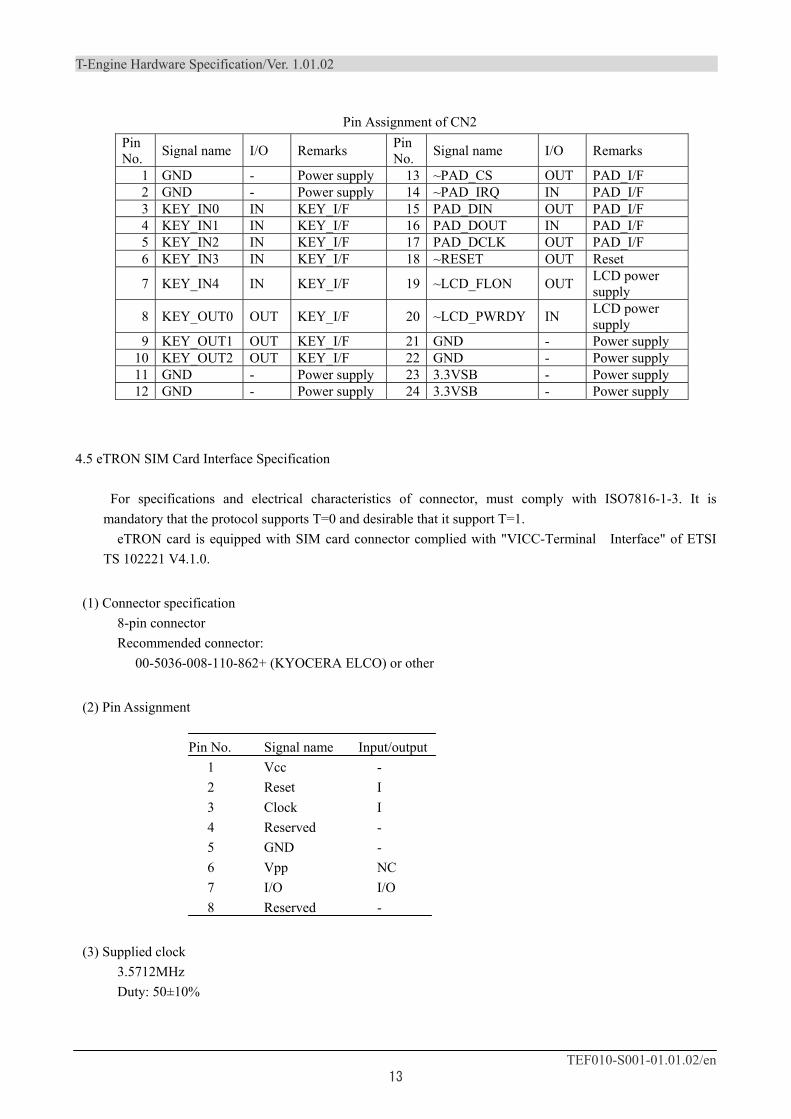
Pin Assignment of CN2
Pin No. Signal name I/O Remarks Pin
No. Signal name I/O Remarks
1 GND - Power supply 13 ~PAD_CS OUT PAD_I/F 2 GND - Power supply 14 ~PAD_IRQ IN PAD_I/F 3 KEY_IN0 IN KEY_I/F 15 PAD_DIN OUT PAD_I/F 4 KEY_IN1 IN KEY_I/F 16 PAD_DOUT IN PAD_I/F 5 KEY_IN2 IN KEY_I/F 17 PAD_DCLK OUT PAD_I/F 6 KEY_IN3 IN KEY_I/F 18 ~RESET OUT Reset
7 KEY_IN4 IN KEY_I/F 19 ~LCD_FLON OUT LCD power supply
8 KEY_OUT0 OUT KEY_I/F 20 ~LCD_PWRDY IN LCD power supply
9 KEY_OUT1 OUT KEY_I/F 21 GND - Power supply 10 KEY_OUT2 OUT KEY_I/F 22 GND - Power supply 11 GND - Power supply 23 3.3VSB - Power supply 12 GND - Power supply 24 3.3VSB - Power supply
4.5 eTRON SIM Card Interface Specification
For specifications and electrical characteristics of connector, must comply with ISO7816-1-3. It is mandatory that the protocol supports T=0 and desirable that it support T=1.
eTRON card is equipped with SIM card connector complied with "VICC-Terminal Interface" of ETSI TS 102221 V4.1.0.
(1) Connector specification 8-pin connector Recommended connector:
00-5036-008-110-862+ (KYOCERA ELCO) or other
(2) Pin Assignment Pin No. Signal name Input/output 1 Vcc - 2 Reset I 3 Clock I 4 Reserved - 5 GND - 6 Vpp NC 7 I/O I/O 8 Reserved -
(3) Supplied clock 3.5712MHz Duty: 50±10%
T-Engine Hardware Specification/Ver. 1.01.02
TEF010-S001-01.01.02/en 14
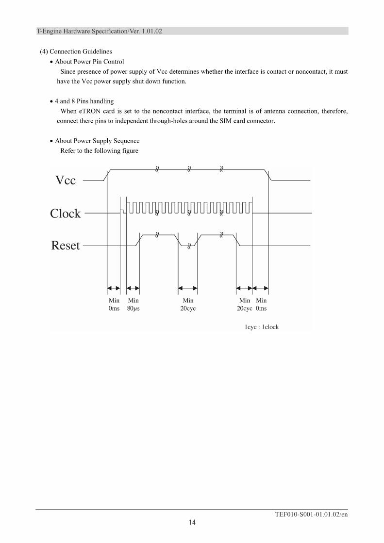
(4) Connection Guidelines • About Power Pin Control
Since presence of power supply of Vcc determines whether the interface is contact or noncontact, it must have the Vcc power supply shut down function.
• 4 and 8 Pins handling When eTRON card is set to the noncontact interface, the terminal is of antenna connection, therefore,
connect there pins to independent through-holes around the SIM card connector.
• About Power Supply Sequence Refer to the following figure
T-Engine Hardware Specification/Ver. 1.01.02
TEF010-S001-01.01.02/en 15
4.6 Interface Specifications of USB Host
Interface complied with USB Host Ver1.1 (12M/1.5Mbps) mounted. Arrange so that the power can be supplied to USB device if the power supply has sufficient capacity such when connecting to the external power supply.
(1) Connector specification 4-pin connector Recommended connector:
20-5041-004-100-834+ (by KYOCERA ELCO) or other
(2) Pin Assignment Pin No. Signal name Input/output 1 Vcc - 2 -Data I/O 3 +Data I/O 4 GND -
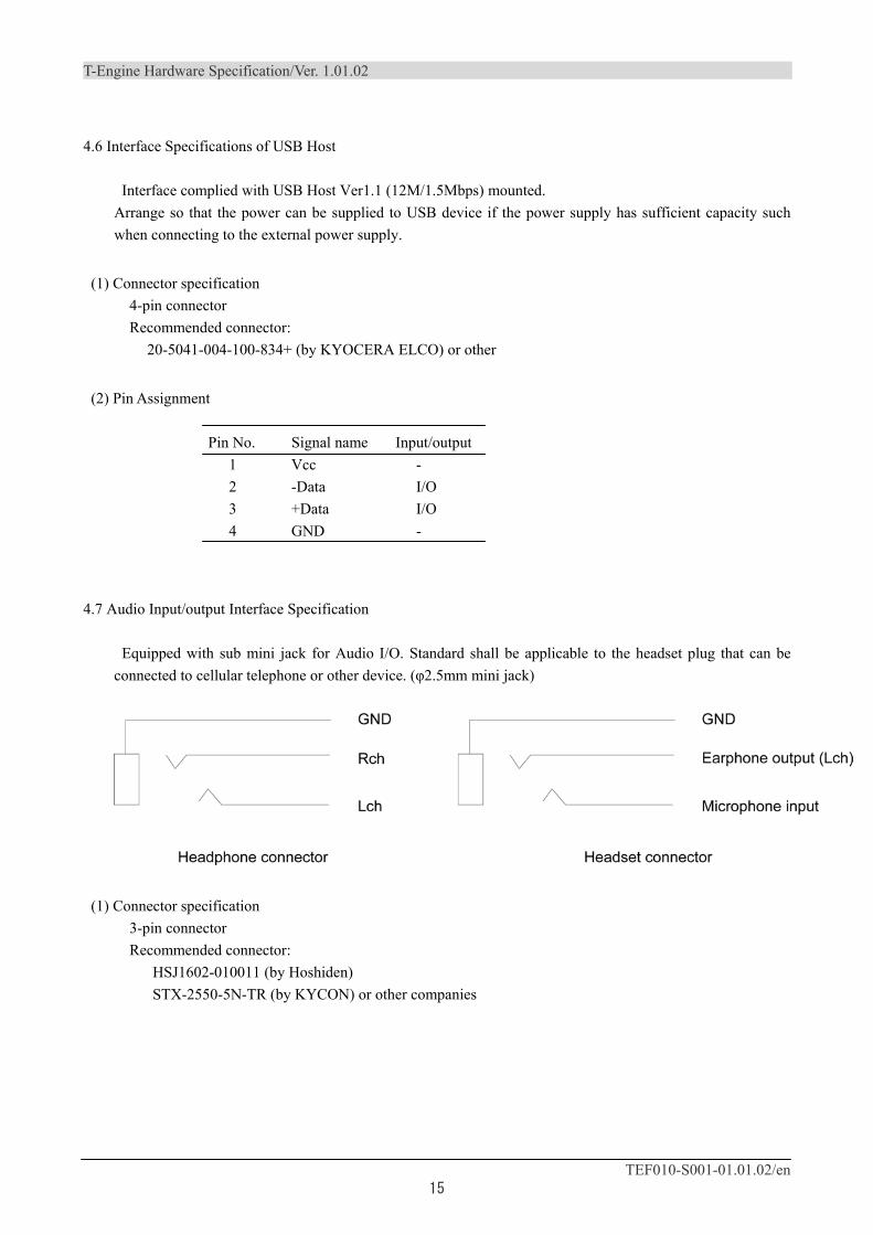
4.7 Audio Input/output Interface Specification
Equipped with sub mini jack for Audio I/O. Standard shall be applicable to the headset plug that can be connected to cellular telephone or other device. (φ2.5mm mini jack)
(1) Connector specification 3-pin connector Recommended connector:
HSJ1602-010011 (by Hoshiden) STX-2550-5N-TR (by KYCON) or other companies
T-Engine Hardware Specification/Ver. 1.01.02
TEF010-S001-01.01.02/en 16
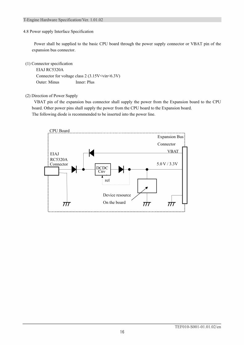
4.8 Power supply Interface Specification
Power shall be supplied to the basic CPU board through the power supply connector or VBAT pin of the expansion bus connector.
(1) Connector specification EIAJ RC5320A Connector for voltage class 2 (3.15V<vin<6.3V) Outer: Minus Inner: Plus
(2) Direction of Power Supply VBAT pin of the expansion bus connector shall supply the power from the Expansion board to the CPU
board. Other power pins shall supply the power from the CPU board to the Expansion board. The following diode is recommended to be inserted into the power line.
DCDCCnv .
VBAT
5.0 V / 3.3V
ref
EIAJ RC5320A
CPU BoardExpansion Bus
Connector
Connector
Device resource
On the board
T-Engine Hardware Specification/Ver. 1.01.02
TEF010-S001-01.01.02/en 17
5. Specifications for Power Control Function of T-Engine Hardware
5.1 System States and their Names
Follow the naming convention shown below when implementing the power management function to T-Engine.
Name: P0 State: Main power OFF Name: P1 State: Main power ON, CPU sleep (startup by interruption available), no memory retained, peripheral modules optional Name: P2 State: Main power ON, CPU sleep (startup by interruption available), memory retained, peripheral modules optional Name: P3 State: Main power ON, CPU activated, memory retained, peripheral modules optional
More detailed naming convention shall be specified when CPU of P3 is activated.
The lowest clock frequency that the CPU can set shall be "1" and the highest frequency shall be the maximum value.
Ex) Low speed: P3-1 Middle speed: P3-2 High speed: P3-3
5.2 Specifications for External Power Supply Control Function
(1) Power ON Control Power ON control supports following 2 types.
Power ON by power activation Power ON by power switch
・Power ON by power activation and that by power switch can be mode switched by DIP switch or other
methods. ・In addition, it is recommended to support the power ON control by power ON control signal on the
expansion bus. ・The power ON by power ON control signal on the expansion bus shall be controlled by inputting the
power ON control signal from the Expansion board with WakeOnLAN function.
(2) Power OFF Control Power OFF by power switch (controlled by software)
T-Engine Hardware Specification/Ver. 1.01.02
TEF010-S001-01.01.02/en 18
Power OFF by other control commands (controlled by software)
5.3 Functions to handle power blackout
It is recommended that T-Engine has the following to handle power blackout.
(1) Power failure detection by backup power supply (UPS, battery, etc.) Select one of following three solutions to realize the power failure detection by backup power supply.
Installation of a signal input pin for power failure notification on the CPU board Introduction of battery voltage drop detection function (in case that battery is equipped.) Installation of a signal input pin for power failure notification on the Expansion board to notify the CPU board of power failure
(2) Power failure detection function using nonvolatile memory, RTC internal register, or other methods
However, the data backup function (such as mounting nonvolatile memory) shall be optional.
T-Engine Hardware Specification/Ver. 1.01.02
TEF010-S001-01.01.02/en 19
6. Regulation and Operation of T-Engine Hardware
6.1 About T-Engine Logo Marking
• Operational Procedures The T-Engine logo marking shall be permitted for the board approved by the executive meeting of the
forum. However, logo marking shall be at each vendor's option.
• Logo Marking Methods Either silk screening, etching, sticker, or other method is available
• Place to Mark anywhere
6.2 Documentation
The following contents shall be described in the specifications on each implementation of T-Engine hardware and user's manual.
(1) CPU Detailed specification: Availability of documents describing the CPU detailed specification or the CPU
specification
(2) RAM Arbitrary
(3) Flash memory Arbitrary
(4) Specifications for Power Supply Control Function Detailed items
(5) Memory Map Detailed items
(6) Specifications for Register Function Detailed items
T-Engine Hardware Specification/Ver. 1.01.02
TEF010-S001-01.01.02/en 20
(7) Expansion Bus I/F Specifications Following specifications:
• Timing specification • Pin allocation specification • Available current • Available voltage • Bus clock • Bus way • CPU allocation space • Interrupt • Others (DMA, etc.)
(8) I/F Specifications for Various Peripheral Devices Describe the specifications of I/F peripheral devices on board, or explain how to obtain the
documentation in which the specifications are described, etc.
6.3 Accreditation Standard of T-Engine Hardware
The procedure to develop the T-Engine and obtain the accreditation of the T-Engine Forum is as follows.
(1) Product Development Start Acquire the registration cord by submitting the registration application sheet accredited by T-Engine to
the T-Engine Forum.
(2) Product Completion Apply the request for T-Engine accreditation to the office.
(3) Examination Development manufacturers shall submit the following target and seek the review.
1. Main body of T-Engine (attachment such as power supply included) 2. Specification 3. Circuit diagram 4. Sample program that allows checking each function 5. Check list
(4) Approval Formal registration is completed once when the T-Engine Forum confirmed that no problem is found
through the above evaluation and hardware is in accordance with T-Engine hardware specification. Then, Product name,etc. will be released in the members-only page of the T-Engine Forum website.
T-Engine Hardware Specification/Ver. 1.01.02
TEF010-S001-01.01.02/en 21
7. Expansion board Standard
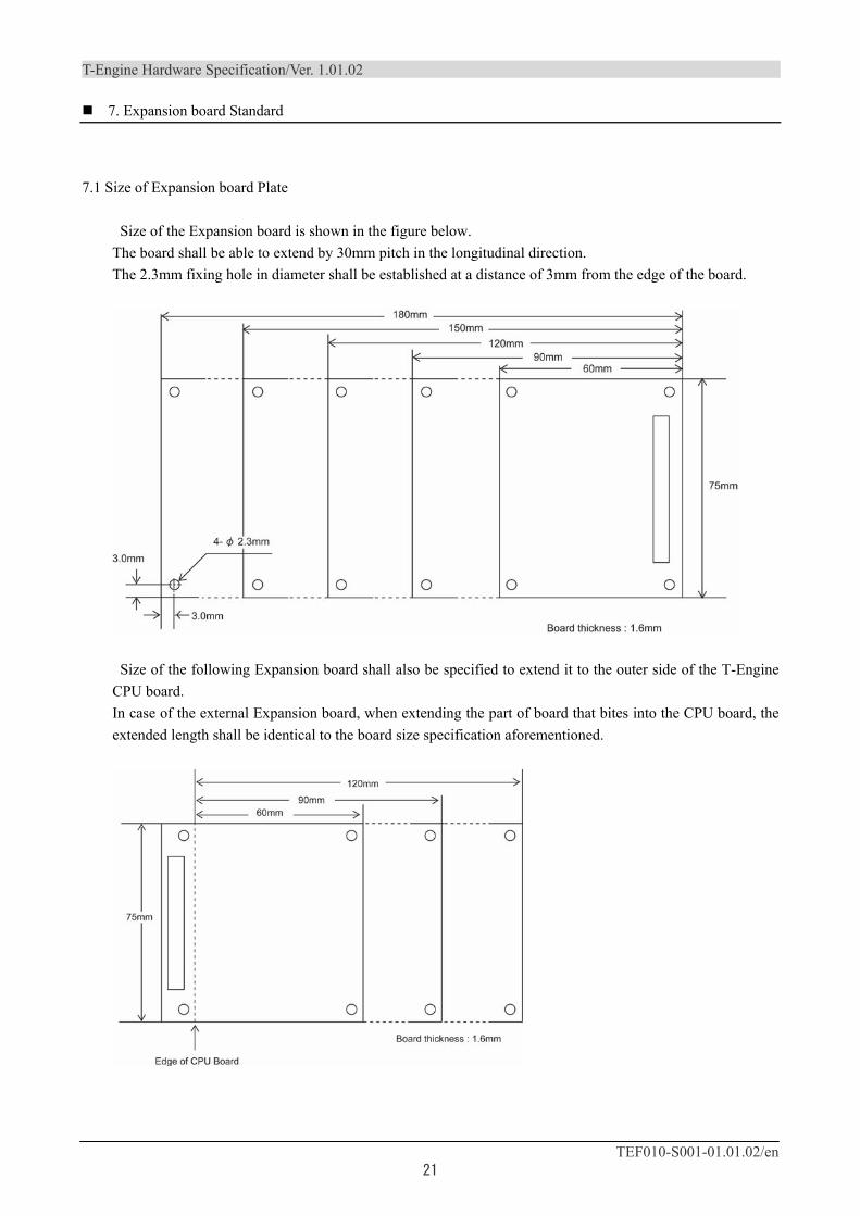
7.1 Size of Expansion board Plate
Size of the Expansion board is shown in the figure below. The board shall be able to extend by 30mm pitch in the longitudinal direction. The 2.3mm fixing hole in diameter shall be established at a distance of 3mm from the edge of the board.
Size of the following Expansion board shall also be specified to extend it to the outer side of the T-Engine CPU board. In case of the external Expansion board, when extending the part of board that bites into the CPU board, the extended length shall be identical to the board size specification aforementioned.

T-Engine Hardware Specification/Ver. 1.01.02
TEF010-S001-01.01.02/en 22
7.2 Restricted Area for Expansion board Implementation
The φ6mm mounting hole for external Expansion board and the 6mm wide around its adjacent hole shall be the restricted area for implementation.
7.3 Stacking Specification for the Expansion board
Stacking Specification for the T-Engine Expansion board is shown below. The interval between boards shall be 10mm.
T-Emgine HardWare Specification / Ver. 1.01.02
TEF010-S001-01.01.02/en 23
T-Engine Hardware Specification (Ver.1.01.02) TEF010-S001-01.01.02/en
T-Engine Forum owns the copyright of this specification. Permission of T-Engine Forum is necessary for copying, republishing, posting on servers, or redistribution to lists of the contents of this specification. The contents written in this specification may be changed without a prior notice for improvement or other reasons in the future. About this specification, please refer to follows;
May 2008
Copyright © 2005-2008 by T-Engine Forum.
T-Engine Forum The 28th Kowa Building 2-20-1 Nishi-gotanda
Shinagawa-Ward Tokyo 141-0031 Japan TEL:+81-3-5437-0572 FAX:+81-3-5437-2399
E-mail:[email protected]