systems-theoretic early concept analysis (and development)
TRANSCRIPT

Systems-Theoretic EarlyConcept Analysis
(and Development)Cody H. Fleming
23 March 20154th STAMP Workshop
Systems Engineering Research Lab
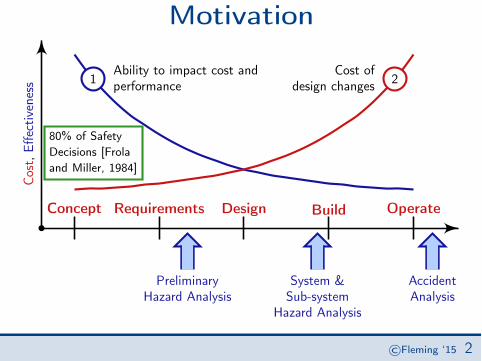
MotivationH
Concept Requirements Design Build Operate
PreliminaryHazard Analysis
System &Sub-system
Hazard Analysis
AccidentAnalysis
Cost
,Effe
ctiv
enes
s 1Ability to impact cost andperformance 2
Cost ofdesign changes
80% of SafetyDecisions [Frolaand Miller, 1984]
©Fleming ‘15 2

General ChallengesH
Concept Requirements Design Build Operate
PreliminaryHazard Analysis
System &Sub-system
Hazard Analysis
AccidentAnalysis
• limited design information• no specification• informal documentation• concept of operations ⌘ “ConOps”
???
©Fleming ‘15 3

Goals
1. use rigorous, systematic tools for identifying hazardous scenarios andundocumented assumptions
2. supplement existing (early) SE activities such as requirementsdefinition, architectural and design studies
✏�
��
Especially when tradespace includes: human operation, automation ordecision support tools, and the coordination of decision making agents
©Fleming ‘15 3

Table of Contents
1. Theory
2. STAMP
3. STECA
4. Case Study
Theory STAMP STECA Case Study©Fleming ‘15

Current State of the ArtH
Concept Requirements Design Build Operate
PreliminaryHazard Analysis
System &Sub-system
Hazard Analysis
AccidentAnalysis
Theory STAMP STECA Case Study©Fleming ‘15 4

Current State of the Art
Preliminary Hazard AnalysisPROGRAM: DATE:ENGINEER: PAGE:ITEM HAZARD
CONDCAUSE EFFECTS RAC ASSESS-
MENTSRECOMM-ENDATIONS
Assignednumber
List thenature ofthecondition
Describewhat iscausing thestatedconditionto exist
If allowed to gouncorrected,what will bethe effect oreffects of thehazardous
condition
HazardLevelassign-ment
Probability,possibility ofoccurrence:-Likelihood-Exposure-Magnitude
Recommendedactions toeliminate orcontrol thehazard
[Vincoli, 2005]
Theory STAMP STECA Case Study©Fleming ‘15 4

Limitations of PHAPHA tends to identify the following hazard causes:
Causes Significance
Self explanatory Equipment Failure High
Causes Significance
algorithmic or programming
implementation
Design error, coding error, insufficient software testing, software operating system problem
Medium
Causes Significance
ANSP makes mistake during manual data load into GBA when
strategic change
Human error Med
[JPDO, 2012]
This is true:ALL accidents are caused by hardware failure, software flaws, or human error⌥⌃ ⌅⇧But is the information coming from PHA useful for systems engineering?
Theory STAMP STECA Case Study©Fleming ‘15 5

EmergenceOrganized complexity as a hierarchy of levels, “each more complex than theone below, a level being characterized by emergent properties which do notexist at the lower level” [Checkland, 1999]
[Business Korea, 2014]
Theory STAMP STECA Case Study©Fleming ‘15 6

HierarchyLevel n
Subsystem
Level n � 1Subsystem
Level 1Subsystem
InterventionFeedback
Input Output
Input Output
Input Output
Feedback
Intervention
[Mesarovic, 1970]
Theory STAMP STECA Case Study©Fleming ‘15 7
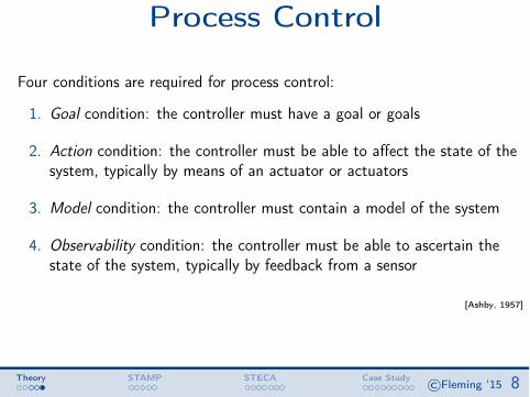
Process Control
Four conditions are required for process control:
1. Goal condition: the controller must have a goal or goals
2. Action condition: the controller must be able to affect the state of thesystem, typically by means of an actuator or actuators
3. Model condition: the controller must contain a model of the system
4. Observability condition: the controller must be able to ascertain thestate of the system, typically by feedback from a sensor
[Ashby, 1957]
Theory STAMP STECA Case Study©Fleming ‘15 8

Table of Contents
1. Theory
2. STAMP
3. STECA
4. Case Study
Theory STAMP STECA Case Study©Fleming ‘15

Safety ) Control ProblemSystems-Theoretic Accident Model and Process
STAMP
• Accidents are more than a chain of events, theyinvolve complex dynamic processes
• Treat accidents as a control problem, not afailure problem
• Prevent accidents by enforcing constraints oncomponent behavior and interactions
Theory STAMP STECA Case Study©Fleming ‘15 9

STAMP• Controllers use a process model to
determine control actions• Accidents often occur when the process
model is incorrect• Four types of unsafe control actions:
1. Not providing the control action causesthe hazard
2. Providing the control action causes thehazard
3. The timing or sequencing of controlactions leads to the hazard
4. The duration of a continuous controlaction, i.e., too short or too long, leads tothe hazard.
Controlled Process
Process Model
Controller
ControlActions
Feedback
Better model of both software and human behaviorExplains software errors, human errors, interaction accidents,. . .
Theory STAMP STECA Case Study©Fleming ‘15 10

STAMP
Controlled Process
Process Model
Controller
ControlActions
Feedback
Theory STAMP STECA Case Study©Fleming ‘15 11

STAMP
Controlled Process
Process Model
Controller
ControlActions
Feedback
Theory STAMP STECA Case Study©Fleming ‘15 11

STAMP
Controlled Process
Process Model
Controller
ControlActions
Feedback
Theory STAMP STECA Case Study©Fleming ‘15 11

STAMP
Controlled Process
Process Model
Controller
ControlActions
Feedback
Theory STAMP STECA Case Study©Fleming ‘15 11

Unsafe Control Actions
55
Table B.3: Unsafe Control Actions for ITP Flight Crew !
Control Action
Not Providing Causes Hazard
Providing Causes Hazard
Wrong Timing/Order Causes Hazard
Stopped Too Soon/Applied Too Long
Execute ITP
ITP executed when not approved ITP executed when ITP criteria are not satisfied ITP executed with incorrect climb rate, final altitude, etc
ITP executed too soon before approval ITP executed too late
Abnormal Termination of ITP
FC continues with maneuver in dangerous situation
FC aborts unnecessarily FC does not follow regional procedures while aborting
Four inadequate control actions of the ITP flight crew are identified as potentially unsafe in B.3. Again, these are self-explanatory: when the flight crew incorrectly executes the ITP or does so out of sequence (which we define as prior to receiving approval or not immediately after receiving approval) or does not initiated an abnormal termination or does so incorrectly, this action may very clearly put the ITP aircraft in proximity of a nearby aircraft. The other inadequate control actions are not highlighted as unsafe for one of three reasons. They are either not unsafe, as is the case of the flight crew not executing IT, they are logically identical to other inadequate control actions (e.g., ITP executed beyond final altitude), or they are illogical (ITP cannot be abnormally terminated if it has not begun or has already completed). The 14 identified unsafe control actions (hazards) can be translated into high-level safety constraints on the air traffic controller and the flight crew:
[SC-ATC.1] Approval of an ITP request must be given only when the ITP criteria are met. (!STPA-ATC.1, [1.14])
Theory STAMP STECA Case Study©Fleming ‘15 12

Control Flaws
ControllerInadequate ControlAlgorithm(Flaws in creation, Processchanges, Incorrectmodification or adaptation)
Process Modelinconsistent,incomplete,or incorrect
Actuator
InadequateOperation
Controlled Process
Component failuresChanges over time
Sensor
InadequateOperation
Controller
2
Inappropriate,ineffectiveor missing
controlaction
Delayedoperation
Incorrect or noinformationprovidedMeasurementinaccuraciesFeedback delays
Inadequate ormissing feedbackFeedback delays
Control input or externalinformation wrong or missing
Unidentified orout-of-rangedisturbance
Conflictingcontrol actions
Process inputmissing or wrong
Process outputcontributes to
hazard[Leveson, 2012]
Theory STAMP STECA Case Study©Fleming ‘15 13

Table of Contents
1. Theory
2. STAMP
3. STECA
4. Case Study
Theory STAMP STECA Case Study©Fleming ‘15

Approach
Systems-theoretic Early ConceptAnalysis—STECA
Theory STAMP STECA Case Study©Fleming ‘15 14

ApproachConcept
ModelGeneration
Model-basedAnalysis
Unspecified assumptions
Missing, inconsistent,incomplete information
Vulnerabilties,risks, tradeoffs
System, software,human requirements
Architectural anddesign analysis
Theory STAMP STECA Case Study©Fleming ‘15 14

Control ElementsConOps
ModelGeneration
Model-basedAnalysis
Unspecified assumptions
Missing, inconsistent,incomplete information
Vulnerabilties,risks, tradeoffs
System, software,human requirements
Architectural anddesign analysis
Theory STAMP STECA Case Study©Fleming ‘15 15

Control Elements
1. Controller
7. ControlAction
6. ControlAlgorithm
5. ProcessModel
2. Actuator
3. Controlled
Process
4. Sensor
Alt.
9. Control input (setpoint)or other commands
8. Feedback to higher levelcontroller
14. ProcessDisturbance
12. Alternatecontrol actions
13. External processinput
15. Process Output
10. Controller output11. External input
Theory STAMP STECA Case Study©Fleming ‘15 16

Roles in Control LoopWhat kinds of things can an “entity” do within a control structure, and moreparticularly within a control loop?
Theory STAMP STECA Case Study©Fleming ‘15 17
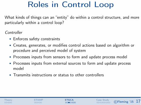
Roles in Control LoopWhat kinds of things can an “entity” do within a control structure, and moreparticularly within a control loop?
Controller• Enforces safety constraints• Creates, generates, or modifies control actions based on algorithm or
procedure and perceived model of system• Processes inputs from sensors to form and update process model• Processes inputs from external sources to form and update process
model• Transmits instructions or status to other controllers
Theory STAMP STECA Case Study©Fleming ‘15 17

Roles in Control LoopWhat kinds of things can an “entity” do within a control structure, and moreparticularly within a control loop?
Actuator• Translates controller-generated action into process-specific instruction,
force, heat, etc
Theory STAMP STECA Case Study©Fleming ‘15 18

Roles in Control LoopWhat kinds of things can an “entity” do within a control structure, and moreparticularly within a control loop?
Controlled Process• Interacts with environment via forces, heat transfer, chemical reactions,
etc• Translates higher level control actions into control actions directed at
lower level processes
Theory STAMP STECA Case Study©Fleming ‘15 19

Roles in Control LoopWhat kinds of things can an “entity” do within a control structure, and moreparticularly within a control loop?
Sensor• Transmits continuous dynamic state measurements to controller (i.e.
measures the behavior of controlled process via continuous orsemi-continuous [digital] data)
• Transmits binary or discretized state data to controller (i.e. measuresbehavior of process relative to thresholds; has algorithm built-in but nocntl authority)
• Sythesizes and integrates measurement data
Theory STAMP STECA Case Study©Fleming ‘15 20

Individual Control Loop
1. Controller
7. ControlAction
6. ControlAlgorithm
5. ProcessModel
2. Actuator
3. Controlled
Process
4. Sensor
Alt.
9. Control input (setpoint)or other commands
8. Feedback to higher levelcontroller
14. ProcessDisturbance
12. Alternatecontrol actions
13. External processinput
15. Process Output
10. Controller output11. External input
Theory STAMP STECA Case Study©Fleming ‘15 21

Control Structure
Controller n
Controller n � 1
Controller 1
Control ActionFeedback
Input Output
Input Output
Input Output
FeedbackControl Action
Theory STAMP STECA Case Study©Fleming ‘15 22

AnalysisConOps
Model Gen-eration
Model-basedAnalysis
Unspecified assumptions
Missing, inconsistent,incomplete information
Vulnerabilties,risks, tradeoffs
System, software,human requirements
Architectural anddesign analysis
Theory STAMP STECA Case Study©Fleming ‘15 23

Analysis
“Completeness”
“Analyzing Safety-related Responsibilities”
“Coordination& Consistency”
Theory STAMP STECA Case Study©Fleming ‘15 23

Early Systems EngineeringConOps
Model Gen-eration
Model-basedAnalysis
Unspecified assumptions
Missing, inconsistent,incomplete information
Vulnerabilties,risks, tradeoffs
System, software,human requirements
Architectural anddesign analysis
Theory STAMP STECA Case Study©Fleming ‘15 24

Early Systems Engineering
Model-Based
Analysis
the control loop can achieve the four necessary conditions2 of process control and ade-
quately interact with its environment, other processes, and other controllers. In other
words, these guide words are necessary to ensure that a control loop is controllable
and coordinable with other controlled processes.
1. Controller7. ControlAction
6. ControlAlgorithm
5. ProcessModel
2.Actuator
3. ControlledProcess
4.Sensor
Controller2
9. Control input(setpoint) or other
commands
8. Feedback to higherlevel controller
14. Processdisturbance
12. Alternatecontrol actions
13. Externalprocess input
15. Processoutput
10. Controlleroutput
11. Externalinput
Figure 11: Control Loop with generic entities
The information in Figure 11 and the above lists (Controller, Actuator, Controlled
Process, Sensor) can then be used to systematically parse and query the natural lan-
guage description or graphical depiction in a concept of operations. The resulting
model and subsequent database are easy to interrogate and visualize. These quali-
ties help the analyst to check for internal inconsistencies and/or missing information
that may result in unsatisfied control conditions, and also to check for inconsistencies
across the system hierarchy.
Table 6 provides a series of prompts that an analyst can use when reading a text or
graphic in a ConOps.
In order to obtain a “complete” model of the ConOps, this model development
approach should be applied recursively over the entire ConOps document. The key-
words, with associated questions and comments (Tables 6 and 7), can be applied to
2 See page 52.
57
Level nSubsystem
Level n � 1Subsystem
Level 1Subsystem
Constraints Feedback
Input Output
Input Output
Input Output
Feedback
Constraints
Figure 8: Basic Features of a Hierarchical System (adapted from [Mesarovic et al.,1970])
the model itself. The process is conducted according to Figure 9, where the main con-
tributions from this extension are represented by the lower four boxes. The following
sub-sections describe the theoretical development as well as provide a brief example
for illustrative purposes.
Like a typical STPA hazard analysis, the systems-theoretic early concept analysis
(STECA) begins with accidents and hazards, a high level decomposition of control
functions, and then a set of high level safety responsibilities. These are basic system
and safety engineering activities that should be done for any project (first box, Figure
9). Chapter 4 provides an example of how to identify a hierarchical list of safety
responsibilities that is based on systems theory.
3.2 Systematic Control Model Development
Potential benefits of model-based systems engineering include the use of repeat-
able processes, promoting consistent views of the system, and formal application
of modeling to support requirements generation, design, analysis, and verification
[Friedenthal et al., 2007]. It is in this vein that this research seeks to develop ConOps
in terms of models rather than informal documentation.
53
Constraintson control
loop behavior
Change thecontrol
structure
Theory STAMP STECA Case Study©Fleming ‘15 24

Table of Contents
1. Theory
2. STAMP
3. STECA
4. Case Study
Theory STAMP STECA Case Study©Fleming ‘15

Application—TBOConOps
Model Gen-eration
Model-basedAnalysis
Unspecified assumptions
Missing, inconsistent,incomplete information
Vulnerabilties,risks, tradeoffs
System, software,human requirements
Architectural anddesign analysis
Theory STAMP STECA Case Study©Fleming ‘15 25

Application—TBOTrajectory-Based Operations (TBO)
Operational Scenarios
Joint Planning and Development Office 1
1
2
3
4
5
6
7
Trajectory-Based Operations (TBO) 8
Operational Scenarios for NextGen 9
Prepared by the 10 Joint Planning and Development Office (JPDO) 11
TBO Study Team 12 13 14 15 16 17 18 19 20 21 22 23 24 25 26 27 28 29
December 4, 2011 30 31 32
Theory STAMP STECA Case Study©Fleming ‘15 25

Application—TBOTrajectory-Based Operations (TBO) Study Team Report
Joint Planning and Development Office
7
Figure 1. Position Uncertainty As the aircraft approaches level-off and cruise, the shape of the protected airspace morphs into more of an elliptical 3-D shape, where the aircraft is positioned in the narrow end of the elliptical shape, with the wake vortex “tail” as its aft bound and vertical, lateral, and longitudinal uncertainty defining the flexible airspace. No two elliptical shapes can overlap if separation is to be assured. In this case, Aircraft A and Aircraft B have crossing trajectories. Aircraft A’s protected space is smaller because it has less uncertainty than Aircraft B. The trailing area of protection may reflect wake turbulence requirements. The lateral protection is the uncertainty in navigation performance, while the leading distance along the flight path represents the time uncertainty. In level flight, the vertical altitude dimension is quite small.
[JPDO, 2011]
Theory STAMP STECA Case Study©Fleming ‘15 25

Application—TBOTrajectory-Based Operations (TBO) Study Team Report
Joint Planning and Development Office
7
Figure 1. Position Uncertainty As the aircraft approaches level-off and cruise, the shape of the protected airspace morphs into more of an elliptical 3-D shape, where the aircraft is positioned in the narrow end of the elliptical shape, with the wake vortex “tail” as its aft bound and vertical, lateral, and longitudinal uncertainty defining the flexible airspace. No two elliptical shapes can overlap if separation is to be assured. In this case, Aircraft A and Aircraft B have crossing trajectories. Aircraft A’s protected space is smaller because it has less uncertainty than Aircraft B. The trailing area of protection may reflect wake turbulence requirements. The lateral protection is the uncertainty in navigation performance, while the leading distance along the flight path represents the time uncertainty. In level flight, the vertical altitude dimension is quite small.
Trajectory-Based Operations (TBO) Study Team Report
Joint Planning and Development Office
8
Figure 2. En Route Uncertainties Defining Conformance Boundaries On arrival, the shape of uncertainty projects downward, based on the descent profile. RNP controls lateral displacement, and time is projected forward to points in space for metering, merging, or initiating the approach as needed for separation, sequencing, merging, and spacing. As the aircraft moves closer to the airport and landing, the uncertainty of vertical profile decreases and the aircraft is now flying in more of a tube-shaped bounded uncertainty, defined laterally by RNP and vertically by the altitude restrictions for the arrival.
[JPDO, 2011]
Theory STAMP STECA Case Study©Fleming ‘15 25

System-Level Hazards
[H-1] Aircraft violate minimum separation (LOS or loss of separation, NMACor Near midair collision)
[H-2] Aircraft enters uncontrolled state[H-3] Aircraft performs controlled maneuver into ground (CFIT, controlled
flight into terrain)
[SC-1] Aircraft must remain at least TBD nautical miles apart en route* "[H-1][SC-2] Aircraft position, velocity must remain within airframe manufacturer
defined flight envelope "[H-2][SC-3] Aircraft must maintain positive clearance with all terrain (This
constraint does not include runways and taxiways) "[H-3]
Theory STAMP STECA Case Study©Fleming ‘15 26

Identify Control ConceptsConOps
ModelGeneration
Model-basedAnalysis
Unspecified assumptions
Missing, inconsistent,incomplete information
Vulnerabilties,risks, tradeoffs
System, software,human requirements
Architectural anddesign analysis
Theory STAMP STECA Case Study©Fleming ‘15 27

Identify Control ConceptsTBO conformance is monitored both in the aircraft and on the groundagainst the agreed-upon 4DT. In the air, this monitoring (and alerting)includes lateral deviations based on RNP..., longitudinal ..., vertical...,and time from the FMS or other “time to go” aids. [JPDO, 2011]
SubjectRole
BehaviorType
Context
Theory STAMP STECA Case Study©Fleming ‘15 27

Identify Control ConceptsTBO conformance is monitored both in the aircraft and on the groundagainst the agreed-upon 4DT. In the air, this monitoring (and alerting)includes lateral deviations based on RNP..., longitudinal ..., vertical...,and time from the FMS or other “time to go” aids. [JPDO, 2011]
Subject Conformance monitoring, Air automationRole Sensor
BehaviorType
Transmits binary or discretized state data to controller(i.e. measures behavior of process relative to thresholds;has algorithm built-in but no cntl authority)Sythesizes and integrates measurement data
Context This is a decision support tool that contains algorithmsto synthesize information and provide alerting based onsome criteria.
Theory STAMP STECA Case Study©Fleming ‘15 27

Identify Control ConceptsTBO conformance is monitored both in the aircraft and on the groundagainst the agreed-upon 4DT. In the air, this monitoring (and alerting)includes lateral deviations based on RNP..., longitudinal ..., vertical...,and time from the FMS or other “time to go” aids. [JPDO, 2011]
1. Controller
- Piloting Function5. Process Model(xa, ya, ha, ta ,...)
2.
3. Controlled Process
-Aircraft
4. Sensor -Altimeter,
FMS, aircraftconformance
monitor
Alt.
(4.)(1.,5.)
(3.)
Theory STAMP STECA Case Study©Fleming ‘15 28

Identify Control ConceptsTBO conformance is monitored both in the aircraft and on the groundagainst the agreed-upon 4DT. In the air, this monitoring (and alerting)includes lateral deviations based on RNP..., longitudinal ..., vertical...,and time from the FMS or other “time to go” aids. [JPDO, 2011]1. Controller Piloting function2. Actuator
3 Cntl’d Process Aircraft4. Sensor Altimeter, FMS, Aircraft conformance monitor
5. Process Model Intended latitude, longitude, altitude, time; Actual latitude,longitude, altitude, time
6. Cntl Algorithm7. Control Actions8. Controller Status
9. Control Input10. Controller Output
11. External Input12. Alt Controller13. Process Input
14. Proc Disturbance15. Process Output
Theory STAMP STECA Case Study©Fleming ‘15 28

GroundIndependent of the aircraft, the ANSP uses ADS-B position reportingfor lateral and longitudinal progress, altitude reporting for vertical, andtools that measure the time progression for the flight track. Data linkprovides aircraft intent information. Combined, this position and timinginformation is then compared to a performance requirement for theairspace and the operation. ...precision needed...will vary based on thedensity of traffic and the nature of the operation. [JPDO, 2011]
Theory STAMP STECA Case Study©Fleming ‘15 29

GroundIndependent of the aircraft, the ANSP uses ADS-B position reportingfor lateral and longitudinal progress, altitude reporting for vertical, andtools that measure the time progression for the flight track. Data linkprovides aircraft intent information. Combined, this position and timinginformation is then compared to a performance requirement for theairspace and the operation. ...precision needed...will vary based on thedensity of traffic and the nature of the operation. [JPDO, 2011]
SubjectRole
BehaviorType
Context
Theory STAMP STECA Case Study©Fleming ‘15 29

GroundIndependent of the aircraft, the ANSP uses ADS-B position reportingfor lateral and longitudinal progress, altitude reporting for vertical, andtools that measure the time progression for the flight track. Data linkprovides aircraft intent information. Combined, this position and timinginformation is then compared to a performance requirement for theairspace and the operation. ...precision needed...will vary based on thedensity of traffic and the nature of the operation. [JPDO, 2011]
Subject Conformance monitoring, Ground automationRole Sensor
BehaviorType
Transmits binary or discretized state data to controller(i.e. measures behavior of process relative to thresholds;has algorithm built-in but no cntl authority)Sythesizes and integrates measurement data
Context This is a decision support tool that contains algorithmsto synthesize information and provide alerting based onsome criteria.
Theory STAMP STECA Case Study©Fleming ‘15 29

GroundIndependent of the aircraft, the ANSP uses ADS-B position reportingfor lateral and longitudinal progress, altitude reporting for vertical, andtools that measure the time progression for the flight track. Data linkprovides aircraft intent information. Combined, this position and timinginformation is then compared to a performance requirement for theairspace and the operation. ...precision needed...will vary based on thedensity of traffic and the nature of the operation. [JPDO, 2011]
1. Controller
- ANSP/Ground5. Process Model(xa, ya, ha, ta ,...,⇢,⌧)
2.
3. Controlled Process
-Piloting Function &Aircraft
4. Sensor -ADS-B, Alt Rep,
time, grdconformance
monitor
Alt.
11. Datalink(4.)(1.,5.)
(3.)
(11.)
Theory STAMP STECA Case Study©Fleming ‘15 30

Conf Monitoring Control Loops
“Ground”
AIRSPACE
Conformance Monitor [Gnd]
Clearancei
GNSS
Alert parameter (G)
GROUND (ANSP / ATC)
{x,y,h,t}i
{4DT}i (Intent)
AltitudeReport
{h}i
DataLink
PMGCAG
Voice DataLink
{4DT}i
TBO Automation
TBO StrategicEvalutation
Theory STAMP STECA Case Study©Fleming ‘15 31

Conf Monitoring Control Loops
“Ground”
AIRSPACE
Conformance Monitor [Gnd]
Clearancei
GNSS
Alert parameter (G)
GROUND (ANSP / ATC)
{x,y,h,t}i
{4DT}i (Intent)
AltitudeReport
{h}i
DataLink
PMGCAG
Voice DataLink
{4DT}i
TBO Automation
TBO StrategicEvalutation
“Air”
Aircraft
ADS-B
Conformance Monitor [Air]
Alert parameter (A)
{x,y,h,t}
4DT
GNSS
AIR (Flight Crew)
CDTI
{x,y,h,t}all
FMS
PMACAA
Manual
Theory STAMP STECA Case Study©Fleming ‘15 31

Hierarchical Control Structure
How to Establish Hierarchy?• Higher level of systems:
. Decision Making Priority
. Decision Complexity, "
. Time Scale betweendecisions, "
. Dynamics of controlledsystem, #
114 PROCEEDINGS OF THE IEEE, JANUARY 1970
A
Fig. 5 . Multilayer hierarchy of decision-making complexity.
I I
I I I
I I
I I I
ORGANIZATION I
I ILEARNING STRATEGY1 I * I
I
LEARNING I I
ADAPTATION I I
AND
OPTIMIZATION
I I [CONiROLl ’1 SELECTION
REGULATION DIRECT C M R R
I
& PROCESS
Fig. 6. Functional multilayer decision hierarchy.
algorithms already exist. The levels in this type of hierarchy are referred to as decision layers or simply layers. As a rule, the solution of the subproblems proceeds sequentially ac- cording to the priority of action postulate; i.e., in the sub- problem on any layer there are some unspecified parameters which are determined by the solution of the subproblems on the higher layer. The subproblem on the lower layer is well defined only after the problem of the higher layer is solved.
Of particular interest in the process control is functional layer hierarchy which follows from the recognition of the three fundamental aspects of the general control (decision) problem under conditions of true uncertainties (Fig. 6) . On the highest layer, the self-organizing layer, the decision unit selects and determines the structure for the lower layers, i.e., the strategies to be used in solving lower layer problems (e.g., it can change parameters in the cost func- tion or the form of the model and performance used on the first layer; similarly, it can change the adaptation or learn- ing strategy used on the second layer). On the second layer, the adaptation or learning layer, the task is to improve the knowledge about the system and environment for the pur- pose of control, to update the model, predict disturbances,
+ 4 PROCESS
Fig. 7. Multilevel, organizational (multiechelon) hierarchy.
and, in general terms, to reduce the uncertainties. Finally, on the first layer, the selection (search, implementation) layer, the task is to determine the control to be actually applied to the process on the basis of the instructions and informa- tion provided from other layers.
In connection with an actual realization of the functional layer hierarchy two remarks are of particular importance.
1) Division of the overall control problem into three layers is conceptual, i.e., in terms of what should be done and when, rather than in terms of how the particular task is to be achieved. Actually, in the process control area the selection layer is realized, as a rule, by two sublayers: the regulatory layer and the optimization layer (Fig. 6). In general, the three layer functional hierarchy is accomplished through a hierarchy of many levels. (The interplay of layers and strata concepts will be discussed later).
2) For each layer there is a different set of methods and techniques. On the direct control layer, feedback control and numerical optimization methods are used; on the adap- tation layer, statistical, pattern recognition, and logical techniques prevail. Finally, on the self-organizing layer one resorts to heuristics. The task of the highest layer cannot be defined in such a way that a simple numerical solution can be attempted and one applies what might be called the “management by exception” approach; i.e., the overall per- formance is evaluated and (structural) change is made only if the performance deteriorates to a degree that warrants such a change.
C. Organizational Hierarchy-Echelons [28], [30] For a variety of practical and conceptual reasons (some
of these will be mentioned later), a vertical decomposition is accompanied by a horizontal decomposition. The resulting hierarchical system, shown in Fig. 7, is referred to as an organizational hierarchy. The kvels are termed echelons. On each level a decision unit (controller) is concerned with a
Theory STAMP STECA Case Study©Fleming ‘15 32

Hierarchical Control Structure
RoutePlanning*
Piloting*
Aircraft
Environment
Function Safety-Related Responsibilities
• Provide conflict-free clearances & trajectories• Merge, sequence, space the flow of aircraft
• Navigate the aircraft• Provide aircraft state information to rte planner• Avoid conflicts with other aircraft, terrain, weather• Ensure that trajectory is within aircraft flight envelope
• Provide lift• Provide propulsion (thrust)• Orient and maintain control surfaces
Theory STAMP STECA Case Study©Fleming ‘15 33

Hierarchical Control Structure
RoutePlanning*
Piloting*
Aircraft
Environment
Function
Aircraft
ADS-B
Conformance Monitor [Gnd]
Conformance Monitor [Air]
Alert parameter (A)
{x,y,h,t}
GNSS
Alert parameter (G)
GROUND (ANSP / ATC)
AIR (Flight Crew)
{x,y,h,t}
{4DT} (Intent)
Route, Trajectory Management
Function
Piloting Function
AltitudeReport
{h}
CDTI
DataLink
FMS; Manual
PMACAA
PMGCAG
4DT;Clearance
Theory STAMP STECA Case Study©Fleming ‘15 33

ConOps
Model Gen-eration
Model-basedAnalysis
Unspecified assumptions
Missing, inconsistent,incomplete information
Vulnerabilties,risks, tradeoffs
System, software,human requirements
Architectural anddesign analysis
Theory STAMP STECA Case Study©Fleming ‘15 34

Analysis
1. Are the control loops complete?2. Are the system-level safety
responsibilities accounted for?3. Do control agent responsibilities
conflict with safety responsibilities?4. Do multiple control agents have the
same safety responsibility(ies)?5. Do multiple control agents have or
require process model(s) of the sameprocess(es)?
6. Is a control agent responsible formultiple processes? If so, how arethe process dynamics (de)coupled?
“Completeness”
“Analyzing Safety-relatedResponsibilities”
“Coordination &Consistency”
Theory STAMP STECA Case Study©Fleming ‘15 34
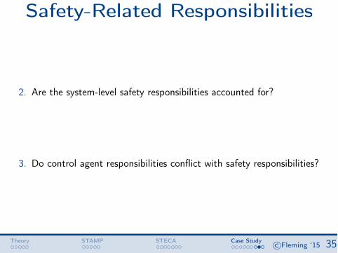
Safety-Related Responsibilities
2. Are the system-level safety responsibilities accounted for?
3. Do control agent responsibilities conflict with safety responsibilities?
Theory STAMP STECA Case Study©Fleming ‘15 35

Safety-Related Responsibilities
• Gaps in Responsibility (2)• Conflicts in Responsibility (3)
(8�i 2 ⌃) (9c 2 C ) [P (c,�i )] , (2)
(8Hi 2 H) (¬9c 2 C ) [P (c,Hi ) ^ P (c,G)] (3)
Theory STAMP STECA Case Study©Fleming ‘15 35

Safety-Related Responsibilities
Potential conflict between goal condition, safety responsibilities???
[JPDO, 2011]“The pilot must also work to close the trajectory. Pilots willneed to update waypoints leading to a closed trajectory in theFMS, and work to follow the timing constraints by flying speedcontrols.”
Theory STAMP STECA Case Study©Fleming ‘15 36

Safety-Related Responsibilities
Theory STAMP STECA Case Study©Fleming ‘15 37

Safety-Related Responsibilities
Theory STAMP STECA Case Study©Fleming ‘15 37

Coordination & Consistency
4. Do multiple control agents have the same safety responsibility(ies)?
5. Do multiple control agents have or require process model(s) of thesame process(es)?
6. Is a control agent responsible for multiple processes? If so, how are theprocess dynamics (de)coupled?
Theory STAMP STECA Case Study©Fleming ‘15 38

Coordination & Consistency
• Coordination Principle (4)• Consistency Principle (5)
(8c 2 Ci ) (8d 2 Cj) 9 (P (c, d) _ P (d, c)) [A (c,Vp) ^ A (d,Vp)] , (4)
(8v 2 V, 8c 2 Ci , 8d 2 Cj | A (c, v) ^ A (d, v))[⇢i (a, v) ⌘ ⇢j(a, v) ^ Gi ⌘ Gj ] (5)
Theory STAMP STECA Case Study©Fleming ‘15 38

Coordination & Consistency
Aircraft
ADS-B
Conformance Monitor [Gnd]
Conformance Monitor [Air]
Alert parameter (A)
{x,y,h,t}
GNSS
Alert parameter (G)
GROUND (ANSP / ATC)
AIR (Flight Crew)
{x,y,h,t}
{4DT} (Intent)
Route, Trajectory Management
Function
Piloting Function
AltitudeReport
{h}
CDTI
DataLink
FMS; Manual
PMACAA
PMGCAG
4DT;Clearance
Theory STAMP STECA Case Study©Fleming ‘15 39
Coordination & Consistency
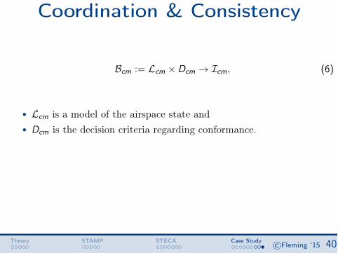
Bcm := Lcm ⇥ Dcm ! Icm, (6)
• Lcm is a model of the airspace state and
• Dcm is the decision criteria regarding conformance.
Theory STAMP STECA Case Study©Fleming ‘15 40

Coordination & Consistency
Lcm := {zint, zact, ⇢,T ,Pr ,W ,Ecm,FD} (7)
zint := {G ,C , t}int
zact := {G ,C , t}act
⇢ := Traffic density⌧ := Operation type
Pr := {RNP,RTP}W := Wake turbulence model
Ecm := Elliptical conformance modelFD := {F , zint}
Dcm = {zact| zact /2 z̄ (zint,Ecm, acm)} , (8)
Theory STAMP STECA Case Study©Fleming ‘15 41

Coordination & Consistency
Aircraft
ADS-B
Conformance Monitor [Gnd]
Conformance Monitor [Air]
Alert parameter (A)
{x,y,h,t}
GNSS
Alert parameter (G)
GROUND (ANSP / ATC)
AIR (Flight Crew)
{x,y,h,t}
{4DT} (Intent)
Route, Trajectory Management
Function
Piloting Function
AltitudeReport
{h}
CDTI
DataLink
FMS; Manual
PMACAA
PMGCAG
4DT;Clearance
Theory STAMP STECA Case Study©Fleming ‘15 42

Coordination & Consistency
Aircraft
ADS-B
Conformance Monitor [Gnd]
Conformance Monitor [Air]
Alert parameter (A)
{x,y,h,t}
GNSS
Alert parameter (G)
GROUND (ANSP / ATC)
AIR (Flight Crew)
{x,y,h,t}
{4DT} (Intent)
Route, Trajectory Management
Function
Piloting Function
AltitudeReport
{h}
CDTI
DataLink
FMS; Manual
PMACAA
PMGCAG
4DT;Clearance
Independent“alertparameter”
Independentconformancemonitors
Theory STAMP STECA Case Study©Fleming ‘15 42
ReferencesAshby, W. R. (1957). An Introduction to Cybernetics. Chapman & Hall Ltd.Business Korea (2014). Auto parts manufacturers concerned over new ordinary wage standards.Checkland, P. (1999). Systems thinking, systems practice: includes a 30-year retrospective. John Wiley & Sons, Inc.Frola, F. and Miller, C. (1984). System safety in aircraft management. Logistics Management Institute, Washington
DC.JPDO (2011). JPDO Trajectory-Based Operations (TBO) study team report. Technical report, Joint Planning and
Development Office.JPDO (2012). Capability safety assessment of trajectory based operations v1.1. Technical report, Joint Planning and
Development Office Capability Safety Assessment Team.Leveson, N. G. (2012). Engineering a Safer World. MIT Press.Mesarovic, M. D. (1970). Multilevel systems and concepts in process control. Proceedings of the IEEE,
58(1):111–125.Strafaci, A. (2008). What does BIM mean for civil engineers? CE News, Tranportation.Vincoli, J. W. (2005). Basic Guide to System Safety, Second Edition. John Wiley & Sons, Inc., Hoboken, NJ, USA.
References Early SE©Fleming ‘15 43

Table of Contents
5. Early SE
References Early SE©Fleming ‘15

Application of ResultsH
Concept Requirements Design Build Operate
PreliminaryHazard Analysis
System &Sub-system
Hazard Analysis
AccidentAnalysis
References Early SE©Fleming ‘15 44

Application of ResultsH
Concept Requirements Design Build Operate
PreliminaryHazard Analysis
System &Sub-system
Hazard Analysis
AccidentAnalysis
What does an engineer need todevelop the system??
References Early SE©Fleming ‘15 44

Application of ResultsConOps
Model Gen-eration
Model-basedAnalysis
Unspecified assumptions
Missing, inconsistent,incomplete information
Vulnerabilties,risks, tradeoffs
System, software,human requirements
Architectural anddesign analysis
References Early SE©Fleming ‘15 44

Deriving RequirementsScenario 2:ANSP issues command that results in aircraft closing (or maintaining) a4DT, but that 4DT has a conflict.
Causal Factors:• This scenario arises because the ANSP has been assigned the
responsibility to assure that aircraft conform to 4D trajectories as wellas to prevent loss of separation.
. A conflict in these responsibilities occurs when any 4D trajectory has aloss of separation (LOS could be with another aircraft that isconforming or is non-conforming). [Goal Condition]
References Early SE©Fleming ‘15 45

Deriving RequirementsScenario 2:ANSP issues command that results in aircraft closing (or maintaining) a4DT, but that 4DT has a conflict.
Causal Factors:• Additional hazards occur when the 4DT encounters inclement weather,
exceeds aircraft flight envelope, or aircraft has emergency
• ANSP and crew have inconsistent perception of conformance due toindependent monitor, different alert parameter setting
• ...
References Early SE©Fleming ‘15 45

Deriving RequirementsScenario 2:ANSP issues command that results in aircraft closing (or maintaining) a4DT, but that 4DT has a conflict.
Requirements:S2.1 Loss of separation takes precedence over conformance in all TBO
procedures, algorithms, and human interfaces [Goal Condition]...
S2.3 Loss of separation alert should be displayed more prominently whenconformance alert and loss of separation alert occur simultaneously.[Observability Condition] This requirement could be implemented in theform of aural, visual, or other format(s).
S2.4 Flight crew must inform air traffic controller of intent to deviate from4DT and provide rationale [Model Condition] ...⌥⌃ ⌅⇧Human factors-related requirements
References Early SE©Fleming ‘15 46

Deriving RequirementsScenario 2:ANSP issues command that results in aircraft closing (or maintaining) a4DT, but that 4DT has a conflict.
Requirements:S2.8 4D Trajectories must remain conflict-free, to the extent possible
...
S2.10 Conformance volume must be updated within TBD seconds of changein separation minima
S2.11 Conformance monitoring software must be provided with separationminima information⌥⌃ ⌅⇧Software-related requirements
References Early SE©Fleming ‘15 46

Deriving RequirementsScenario 2:ANSP issues command that results in aircraft closing (or maintaining) a4DT, but that 4DT has a conflict.
Requirements:S2.14 ANSP must be provided information to monitor the aircraft progress
relative to its own “Close Conformance” change of clearance...
S3.2 ANSP must be able to generate aircraft velocity changes that close thetrajectory within TBD minutes (or TBD nmi).Rationale: TBO ConOps is unclear about how ANSP will help the aircraft work toclose trajectory. Refined requirements will deal with providing the ANSP feedbackabout the extent to which the aircraft does not conform, the direction and time,which can be used to calculate necessary changes.⌥⌃ ⌅⇧Component Interaction Constraints
References Early SE©Fleming ‘15 46

Architecture StudiesConOps
Model Gen-eration
Model-basedAnalysis
Unspecified assumptions
Missing, inconsistent,incomplete information
Vulnerabilties,risks, tradeoffs
System, software,human requirements
Architectural anddesign analysis
References Early SE©Fleming ‘15 47

Architecture StudiesNegotiation
Trajectory-Based Operations (TBO) Study Team Report
Joint Planning and Development Office
10
TBO relies on data link for the majority of the air-to-air, air-to-ground and ground-ground communications. There may be multiple data links involved in TBO, ranging from delivery of advisory information to the actual loading of a new 4DT that affects the flight path of the aircraft. This variation in message content drives different data link performance requirements. Much of the messaging is advisory in nature, but the actual clearance for the 4DT and confirmation of use of this information have higher performance requirements. An aircraft may be connected to network-centric operations over multiple data links, but there will be a specified, performance-driven path for the critical communication of 4DT information. Figure 4 is a depiction of notional communication flows.
Figure 4. TBO Information Flows The numbers in Figure 4 identify the possible communications paths. Path 1 is the network-centric operations connectivity, a ground-ground communications used by the airline, military, or larger GA operation with dispatch services that connects the operator to the ANSP. For those operators lacking a dispatch service, this communications path may be supported by a third-party vendor and used by pilots to plan a flight and provide their desired 4DT to the ANSP. Path 1 is the principal path for flight- following activities by the airlines. Path 2 represents a user-specified performance for exchange of information between the flight crew and operations. For strategic changes to the 4DT under TBO, this communications path could be used to coordinate between the flight crew and operations, and then the Airline Operations Center/Flight Operations Center (AOC/FOC) could negotiate with the ANSP. Path
[JPDO, 2011]
References Early SE©Fleming ‘15 47

TBO Negotiation
FOCi
Aircrafti1
ANSP
Aircrafti2 Aircraftik
FOCj
Aircraftj1 Aircraftj2 Aircraftjl
Flight Deck1 Flight Deckm
PMACAA
PMOCAO PMOCAO PMFCAF PMFCAF
KAO LA
O KAO LA
OKA
F LAF
KAF LA
F
KAF LA
F
KAF LA
FKAF LA
F
KAFLA
F
KAFLA
FKA
FLA
F
KOF
LOF
KOF LO
F
KOF
LOF
KOF LO
F KOF
LOF
KOF
LOF
References Early SE©Fleming ‘15 48

Modified Structure
FOCi
Aircrafti1
ANSP
Aircrafti2 Aircraftik
FOCj
Aircraftj1 Aircraftj2 Aircraftjl
Flight Deck1 Flight Deckm
PMACAA
PMOCAO PMOCAO PMFCAF PMFCAF
KAO
LAO
KAO
LAO KA
F LAF
KAF
LAF
KOF
LOF
KOF LO
F
KOF LO
F
KOF LO
F KOF LO
F
KOF LO
F
References Early SE©Fleming ‘15 49

Modified Structure
FOCi
Aircrafti1
ANSP
Aircrafti2 Aircraftik
FOCj
Aircraftj1 Aircraftj2 Aircraftjl
Flight Deck1 Flight Deckm
PMACAA
PMOCAO PMOCAO PMFCAF PMFCAF
KAO
LAO
KAO
LAO KA
F LAF
KAF
LAF
KOF
LOF
KOF LO
F
KOF LO
F
KOF LO
F KOF LO
F
KOF LO
F
✏�
��
Additional Requirement: KAF and KO
F shall notoccur simultaneously.
References Early SE©Fleming ‘15 49

Modified StructureANSP
Flight Deck4 Flight Deckm
PMACAA
PMFCAF PMFCAF
FOCi FOCj
PMOCAO PMOCAO
Flight Deck1
PMFCAF
Flight Deck2
PMFCAF
Flight Deck3
PMFCAF
KAF LA
F KAF LA
FKA
F LAF KA
F LAF KA
F LAF
IOF
IOF
IOF
References Early SE©Fleming ‘15 50
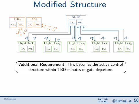
Modified StructureANSP
Flight Deck4 Flight Deckm
PMACAA
PMFCAF PMFCAF
FOCi FOCj
PMOCAO PMOCAO
Flight Deck1
PMFCAF
Flight Deck2
PMFCAF
Flight Deck3
PMFCAF
KAF LA
F KAF LA
FKA
F LAF KA
F LAF KA
F LAF
IOF
IOF
IOF
✏�
��
Additional Requirement: This becomes the active controlstructure within TBD minutes of gate departure.
References Early SE©Fleming ‘15 50

EvaluationH
Concept Requirements Design Build Operate
Systems Engineering Phases
PreliminaryHazard Analysis
System &Sub-system
Hazard Analysis
AccidentAnalysis
Safety Activities
References Early SE©Fleming ‘15 51

EvaluationH
Concept Requirements Design Build Operate
Systems Engineering Phases
PreliminaryHazard Analysis
System &Sub-system
Hazard Analysis
AccidentAnalysis
Safety Activities
“PHA”“STECA”
References Early SE©Fleming ‘15 51