systems reference library ibm operating …...systems reference library ibm operating system/360...
TRANSCRIPT
Systems Reference Library
IBM Operating System/360
Concepts and Facilities
This publication describes the basic concepts of Operating System/360 and guides the programmer in the use of its various facilities.
Operating System/360 is a comprehensive set of language translators and service programs, operating under the supervisory control and coordination of an integrated control program. It is designed for use with Groups 30, 40, 50, 60, 62, 70, and 92 of Computing System/360. It assists the programmer by extending the performance and application of the computing system.
File Numbel: 8360-36 Form C28-6535-0

PREFACE
This publication introduces and interrelates all Operating System/360 control program facilities. It shows how these facilities work with the language translators and service programs, so the programmer can better learn to use the system. It also directs the programmer to related Operating System/360 publications for specific details.
Many combinations of programming facilities are possible with Operating System/360. The programmer will work with a particular set of these facilities, depending on the language he uses (FORTRAN, COBOL, Report Program Generator, Assembler, or New Programming Language), and the modular programs chosen when his operating system is generated. Although all the control program facilities are described herein, all of them may not be included in every installation.
The publication is divided into two parts, an introduction and survey, and a detailed description. The first part contains a general description of subjects of interest to all users. The second part, meant for programmers, is a more thorough discussion of the same topics.
Even though many details are expressed in assembler language terminology, this publication is addressed to every programmer who will use System/360, and familiarity ~ith the assembler language is not a requirement.
PREREQUISITE PUBLICATION: IBM Operating System/360: Introduction. This publication describes the general organization, function, and application of the operating system. It also describes the other related Operating System/360 publications.
This publication was prepared for production using an IBM computer to update the text and to control the page and line format. Page impressions for photo-offset printing were obtained from an IBM 1403 Printer using a special print chain.
Copies of this and other IBM publications can be cbtained through IBM Branch Offices.
A form for readers' comments appears at the back of this publication. It may be mailed directly to IEM. Address any additional comments concerning this publication to the IBM Corporation, programming Systems publications, Department D58, PO Box 390, Poughkeepsie, N. Y. 12602
©1965 by International Business Machines Corporation

PART I: INTRODUCTION AND SURVEY ••
SECTION 1: INTRODUCTION.
Elements of the Ope:r:ating System
Benefits to the Programmer !
SECTION 2: SURVEY
Data Management • Identifying and Locating Data Organizing Data •••• Storing and Retrieving Data • • • • Device Independence • • • • •
Program Design and Preparation programs and Subprograms • Combining Subprograms
Job Management ••••• Job Control ••••• The Input Job Stream • Job Scheduler ••••••••
Sequential Scheduling System Priority Scheduling Systems
Task Management •
PART II: DETAILED DESCRIPTION
SECTION 3: DATA MANAGEMENT
Data Set Identification and Extent Control ••••••• • • • •
Direct-Access Volume Identification and the Volume Table of Contents
Magnetic Tape Volumes ••••••• Cataloging and Library Management
Control Volumes • • • • • • • Generation Data Groups •••••
Password Protection of Data Sets • • Editing of Space, Indexes, and Catalogs ••••
Data Access Methods • The Access Methods • •
Queued Sequential Access Method (QSAM) • • • • • • • • • •
Basic Sequential Access Method (BSAM) • • • • • • • • • • • • •
Basic Partitioned Access Method (BPAM) • • • • • • • • • • • • •
Indexed Sequential Access Methods - Basic and Queued (BISAM and QISAM) • • • • • • • • • • • • •
Basic Direct~Access Method (BDAM) Queued Telecommunications Access
Method (QTAM) ••••••••• Basic Telecommunica.tions Access
Method (BTAM) •••••••••
7
8
8
8
10
10 10 11 11 12
13 13 13
15 15 15 16 16 17
18
21
22
22
22 22 23 24 24 25
25
25 26
26
26
26
26 27
27
29
CONTENTS
Blocking and Buffering Facilities 29 Block Formats • • • • • 29 Buffering Facilities •••••• 30 Buffer Pools •••••••••• 30 Buffer Assignment Techniques and Transmittal Modes 30
The Data Control Block 33 OPEN and CLOSE Macro-Instructions 33 Data Access Routines • • • • •• 34
SECTION 4: PROGRAM DESIGN AND PREPARATION ••• •
Program Segmentation
Program Structures Simple Structures ••••
Deferred Exits Planned OVerlay Structures Dynamic Serial Structures
Link Macro-Instruction Transfer Control (XCTL) Macro-Instruction
LOAD Macro-Instruction Planned Overlay versus Dynamic Structures • • • • • • • •
Dynamic Parallel Structures • • • •
Program Design Facilities • • • • Reusability ••••• • • • • Design of Reenterable Programs Checkpoint and Restart • • Timer •• • • • •
Debugging Facilities Assembler Language Program
Debugging: Test Translator Test Output •••••
SECTION 5: JOB MANAGEMENT
Control Statement Capabilities Scheduling Controls
Job Priority Dependencies Maximum Execution Time Non-Setup Jobs •••• Job Log • • • • •
Program Source Selection • Data Set Identification And Disposition • • • • • • • • •
SYSIN and the DD * Statement Concatenated Data Sets Generation Data Groups Dummy Data Sets • • • • Data Set Disposition • • • •
Input/Output Device Allocation Deferred Mounting of Tapes
Direct-Access Storage Space Allocation ••••• • • • • •
39
39
39 40 41 42 43 43
44 45
46 46
47 47 48 49 49
50
50 51
52
52 53 53 53 53 53 54 54
54 55 55 55 55 56 56 58
58
11 S
Cataloged pr9cedures • • • • • • •• 58 Job Scheduler and Master Scheduler Functions • • • • • • • • • • • 58
Job Scheduler •••• 59 Reader/Interpreter ••••••• 59 Initiator/Terminator • • • • 59 Output Writers 60
Master Scheduler • • • • • 61
SECTION 6: TASK MANAGEMENT
Single-Task Operations Actual Flow of Control
Multitask Operation ••• Task Creation -- ATTACH Resource Allocation
Tasks As Users of Resources • passing Resources to Subtasks
Event Synchronization ••••• WAIT and POST Macro-Instructions Enqueue (ENQ) and Dequeue (DEQ) Macro-Instructions
Task Priorities Task Termination • • •
Main Storage Allocation • Main Storage Allocation in a Multitask Environment
Storage Protection And Protection Boundaries ••••••••••••
63
63 64
64 65 66 67 68 68 68
70 71 72
74
75
75
Passing And Sharing Of Main Storage Areas • • • • • • • • • • • •
Task Priorities And Roll-Out •
APPENDIX: SYSTEM CONVENTIONS
Names ••
Subprogram Linkage
Program sharing • •
Intertask communication •
Use of WAIT • • • •
Operator messages •
Control Section size
Character set considerations Source Language Debugging and Maintenance
Volume Labels
Track Address Independence
GLOSSARY
INDEX ••
75 76
77
77
78
78
78
78
'78
78
78
79
79
79
80
87
$

FIGURES
Figure 1. Figure 2.
Figure 3.
Figure 4. Figure 5. Figure 6.
Figure 7. Figure 8. Figure 9.
Figure 10.
~"igure 11. Figure 12.
Figure 13. Figure 14. Figure 15.
Figure 16.
Figure 17.
Figure 18.
Figure 19.
Figure 20.
Figure 21. Figure 22. Figure 23. Figure 24. Figure 25. Figure 26.
Figure 2 7.
Figure 28.
Figure 29.
Operating System/360 . • • Subprograms Existing at Different Levels of Control
Subprograms Existing at the Same and Different Levels of Control • • • • • • Program Preparation. • The Input Job Stream • • • Sequential Scheduling System • • • • • • • • Priority Scheduling System Task Representation. • • • Switching Control Among Tasks ••••••••••• Volume Initialization and the Volume Table of Contents
Catalog Search Procedure • The Queued Telecommunications Access Method • • • • • • • • • • Components of a Message •• Dynamic Buffering ••••• Simple Buffering - Move Mode • • • • • • • • • • • Simple Buffering - Locate Mode • • • • • • • • Exchange Buffering -Substitute Mode •••••• Data Control Block Being Filled in. • • • • . • • Actual Program Flow That Starts on Input/Output • . Execution of a Load Module Within a Task •••.• ~ • Subprogram Within a Program Deferred Exit to Subroutine Overlay Tree Structure The LINK Operation . Nested Subprograms • • Use of XCTL MacroInstructions • . • • Uses of LOAD MacroInstructions • • .. . Immediate Requirement for Subprogram . • . • . • • Delays Expected in Higher Level Subprograms ...•.
8
13
14 14 15
16 17 18
19
23 24
28 29 31
32
32
33
34
35
40 40 42 42 44 45
45
46
46
47
Figure 30.
Figure 31. Figure 32.
Figure 33.
Figure 34.
Figure 35. Figure 36. Figure 37.
Figure 38.
Figure 39.
Figure 40.
Figure 41. Figure 42. Figure 43. Figure 44.
Figure 45.
Figure 46.
Figure 47.
Figure 48.
TABLES
Table 1. Table 2.
Table 3.
ILLUSTRATIONS
Delays Expected in Sub-program • •• .•••. No Delays Expected. . . . A Reenterable Program that Requests Its Own Temporary Storage •• .... Chain of Symbolic References ...•.. Typical Input/Output Devices • • • • • • • • • Multijob Initiation • Actual Flow of Control. • Job Step-Task Relation-ship. . . . . . . . . . . Situation Immediately After Initial Program Loading • Situation With Reader, Writer, Initiator, and One Job Step. • • • • • • Situation After Initiating Three Concurrent Jobs • • Resource Queues • • • • • Intertask Synchronization Situation After READ ••• Situation After Execution of WAIT • • • . • • • • • Situation at Completion of Input/Output Operation
Abnormal Termination of a Task. • • • . • • • • • • Abnormal Termination of a Subtask • • • • • • • • • Deferred Exit at Abnormal End of Task • • • • • • •
Access Method Summary Names of Installation Devices. ••.•• Specifications That Achieve Input/Output Overlap • • • • • • •
47 47
49
54
56 60 64
65
66
66
66 68 69 69
70
70
73
73
74
37
58
59


PART I: INTRODUCTION AND SURVEY
This part contains a concise description of the significant features of the operating system. It is intended to serve as an introduction to the concepts, facilities, and terminology described in greater detail in Part II and in other Operating System/360 Publications.
Since the Survey is self-contained, however, it should also prove useful to anyone wanting a general familiarity with the system.
7

SECTION 1: INTRODUCTION
Operating System/360 has been designed to shorten the period between the time a problem is submitted for solution and the time results are received 7 to increase the volume of work that can be handled over a given period of time7 and to assist those concerned with the system: installation managers, operators, and above all, programmers. The operating system consists of a number of processing programs and a control program (Figure 1).
Operating System/360
Control Program
Data Management
Function
Job Management
Function
Task Management
Function
Processing Programs
Language Translators
• New Programming Language
• FORTRAN • COBOL • Assembler • Report
Program Generator
• Telecommuni-cations Program Generator
• System Generator
• Test Translator
Service Programs
• Linkage Editor
• Sort/Merge • Utilities
User-Written
Problem Programs
Figure 1. Operating System/360
8
ELEMENTS OF THE OPERATING SYSTEM
The processing programs consist of language translators, service programs, and user-written problem programs. The programmer uses them to define the work that the computing system is to perform and to simplify program preparation.
The control program supervises the execution of the processing programs7 controls the location, storage, and retrieval of data 7 and schedules jobs for continuous processing.
S~stem users may also include their own serv1ce programs or language translators. The programmer can then use these programs as he would use IBM-written programs.
BENEFITS TO THE PROGRAMMER
The programmer can take advantage of a unified system that allows him:
• To write programs that are independent of input/output requirements or characteristics of the operating environment. Such requirements can be specified when the jobs are set up, without modifying the programs.
• To place information (programs or collections of data) in the system's library without specifying or keeping track of the identification of the auxiliary storage volume used7 and then to obtain access to the information by merely providing a symbolic reference to it. The system automatically locates the information, issues instructions to the operator to place the information on-line, and provides the descriptive material that is subsequently used to retrieve the information properly.
• To store frequently used series of statements that specify job requirements as ncataloged procedures,n and to easily call them for use.
• To receive the results of a computer run soon after submitting a job because of a nonstop operation that does not require jobs to be delayed until a batch is accumulated.
• To design efficient programs that make balanced use of system resources in an easy and direct way. Programs may

be divided into simple subprograms that are executed concurrEmtly under management of the control program; there is no need to rely on a complex, intricate design to achieve thE~ same effect.
• To divide a problem into a set of subprograms, and codE~ each in the language best suited to it.
• To divide a large program into smaller sections that can be overlayed after they have been executed, to conserve main storage space.
• To easily test and modify programs and data.
• To choose between immediately executing compiled or assembled programs (or parts of programs) or storing them on auxiliary devices for later use with other compiler or assembler outputs. The system can locatE~ such routines if given only their names, and can pass control to them in several different ways.
• To use the piling it, chooses to program.
same program without recomeven if the installation add features to the control
The various facilities provided by processing programs and the control program are described under four topics:
• Information to be processed is organized and stored in a particular way related to its use. It may be named and may be easily retrieved. These operations are described. under Data Management. ----
• The user's programs are prepared under certain constraints, such as available storage space and the characteristics of the problem to be solved. The programmer should take full advantage of available programming aids (such as inclusion of existing subroutines) • System features in this area are described under Program Design and Preparation.
• Processes can be specified as sequences of steps. These steps are then scheduled to maintain a continuous flow; this is described under Job Management.
• Elements of work can be performed individually or concurrently. This is described under Task Management.
Section 1: Introduction 9

SECTION 2: SURVEY
DATA MANAGEMENT
The manner in which data is transferred between main storage and external devices is of paramount importance in most dataprocessing installations. Earlier systems provided a number of facilities that together were named an input/output control system (IOCS). Most of these systems were limited to tape and unit record equipment. They consisted primarily of routines that managed buffers and hardware interfaces, and controlled access to labeled tapes. Other versions, usually independent, included facilities for reading and writing on direct-access devices, and still others controlled telecommunications activities. Facilities to build and retrieve from program libraries were at times also available, but were usually not incorporated into the input/output control systems.
The data management facilities of Operating System/360 handle all of these functions, and do it in a consistent manner. Data from a direct-access device, a remote terminal, or a tape; data organized sequentially, or like a library; all may be requested by the programmer in essentially the same way.
In addition, data management provides:
• Allocation of space on direct-access devices. Flexibility and efficiency of these devices is improved through better use of available space.
• Automatic location of data sets* by name alone.
• Freedom to defer specifications such as buffer size, blocking factors, device identification, and device type until the job is submitted for processing. This permits the creation of programs that are in many ways independent of their operating environments.
• Protection of data sets. This includes:
1. Protection of data sets that share a common device. An accidental attempt to write outside of specified boundaries is detected and prevented.
2. Protection against unauthorized
*Collections of data, described by control information stored within the system, are called "data sets" as opposed to the more common term "file."
10
access to security files (containing, for example, payroll information) by use of npasswords.n
3. Protection against concurrent updates of the same record, in multiprogrammed systems.
The following paragraphs describe the means of identifying, locating, organizing, storing, and retrieving data in general terms. Data management is discussed in greater detail in Section 3.
IDENTIFYING AND LOCATING DATA
Whenever a programmer indicates that a new data set is to be created and placed on auxiliary storage, he (or the control program) must give the data set a name. The name is used when the data is to be retrieved.
In some cases, the name assigned to a data set must be qualified to avoid ambiguity. For example, the qualified names COLOR. CHERRY and TREE.CHERRY describe two qifferent data sets having the simple name CHERRY.
A standard unit of auxiliary storage is called a volume. A volume may be, for example, any of the following:
• A reel of tape • A disk pack • A data cell • A drum • The part of an IBM 2302 Disk Storage
device served by one access mechanism (the device would have either two or
four volumes in all)
A direct-access volume (everyone of the above except the tape reel) has a volume ~abel in a standard location. The label specifies the location of a volume table of contents. Each data set stored on the volume has its name, location, organization, and other control information stored in the table of contents. (Similar information is stored in labels of data sets stored on tape.) Thus, if the name of a data set and the volume on which it is stored is made known to the control program, a complete description of the data set, including its location on the volume, can be retrieved. Following this, the data itself can be retrieved, or new data can be added to the data set.
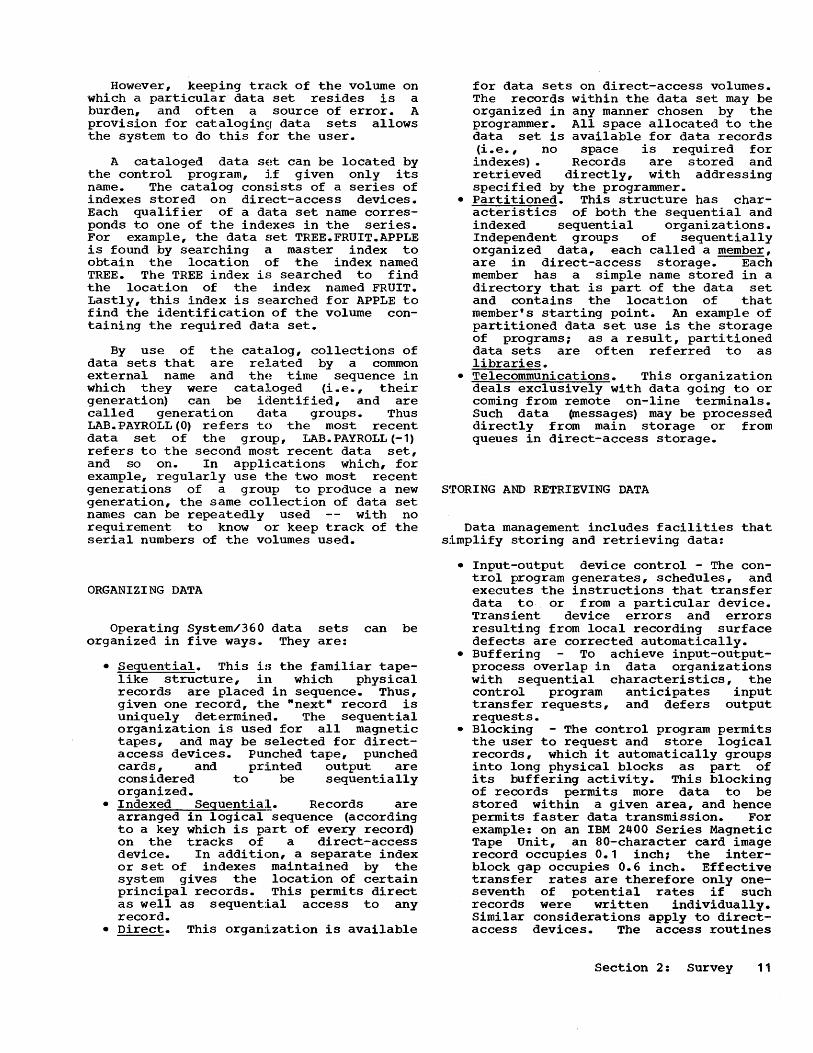
However, keeping track of the volume on which a particular data set resides is a burden, and often a source of error. A provision for catalogin9 data sets allows the system to do this for the user.
A cataloged data SE~t can be located by the control program, if given only its name. The catalog consists of a series of indexes stored on direct-access devices. Each qualif ier of a delta set name corresponds to one of the indE~xes in the series. For example, the data set TREE.FRUIT.APPLE is found by searching cl master index to obtain the location of the index named TREE. The TREE index is searched to find the location of the index named FRUIT. Lastly, this index is searched for APPLE to find the identification of the volume containing the required dat:a set.
By use of the catalog, collections of data sets that are related by a common external name and the time sequence in which they were cataloged (i.e., their generation) can be identified, and are called generation data groups. Thus LAB. PAYROLL (0) refers to the most recent data set of the group, LAB. PAYROLL (-1) refers to the second mo~~t recent data set, and so on. In applications which, for example, regularly use t.he two most recent generations of a group to produce a new generation, the same collection of data set names can be repeatedly used with no requirement to know or keep track of the serial numbers of the volumes used.
ORGANIZING DATA
Operating System/360 data sets can be organized in five ways. They are:
• Sequential. This is the familiar tapelike structure, in which physical records are placed in sequence. Thus, given one record, the "next" record is uniquely determined. The sequential organization is used for all magnetic tapes, and may be selected for directaccess devices. Punched tape, punched cards, and printed output are considered to be sequentially organized.
• Indexed Seguentia:~. Records are arranged in logical sequence (according to a key which is part of every record) on the tracks of a direct-access device. In addition, a separate index or set of indexes maintained by the system gives the location of certain principal records. This permits direct as well as sequential access to any record.
• Direct. This organization is available
for data sets on direct-access volumes. The records within the data set may be organized in any manner chosen by the programmer. All space allocated to the data set is available for data records (i.e., no space is required for indexes) • Records are stored and retrieved directly, with addressing specified by the programmer.
• Partitioned. This structure has characteristics of both the sequential and indexed sequential organizations. Independent groups of sequentially organized data, each called a member, are in direct-access storage. Each member has a simple name stored in a directory that is part of the data set and contains the location of that member's starting point. An example of partitioned data set use is the storage of programs; as a result, partitioned data sets are often referred to as libraries.
• Telecommunications. This organization deals exclusively with data going to or coming from remote on-line terminals. Such data ~essages) may be processed directly from main storage or from queues in direct-access storage.
STORING AND RETRIEVING DATA
Data management includes facilities that simplify storing and retrieving data:
• Input-output device control - The control program generates, schedules, and executes the instructions that transfer data to or from a particular device. Transient device errors and errors resulting from local recording surface defects are corrected automatically.
• Buffering To achieve input-out put-process overlap in data organizations with sequential characteristics, the control program anticipates input transfer requests, and defers output requests.
• Blocking - The control program permits the user to request and store logical records, which it automatically groups into long physical blocks as part of its buffering activity. This blocking of records permits more data to be stored within a given area, and hence permits faster data transmission. For example: on an IBM 2400 Series Magnetic Tape Unit, an SO-character card image record occupies 0.1 inch; the interblock gap occupies 0.6 inch. Effective transfer rates are therefore only oneseventh of potential rates if such records were written individually. Similar considerations apply to directaccess devices. The access routines
Section 2: Survey 11
for these facilities are called by simple input/output macro-instructions or statements in each program's source coding. Two categories of access language are provided to satisfy specific user requirements.
The queued access language is designed to furnish a full range of buffering and blocking facilities with maximum programming simplicity. It applies only to organizations with sequential characteristics. The macro-instructions GET and PUT are used for retrieval and storage of logical records.
The basic access language furnishes device control without automatic buffering and blocking. Input/output operations are scheduled at the time they are requested. Characteristically, the macro-instructions READ and WRITE retrieve and store entire physical blocks of data.
This more primitive language may be used to give the programmer more direct control over functions such as seeking, backspacing tape, etc., that depend on particular input/output devices. It also may serve as the base for any special buffering or blocking methods constructed by the user.
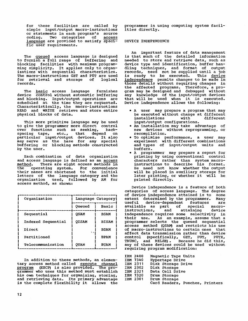
Each combination of data organization and access language is defined as an access method. There are eight access methods in the operating system. For convenience their names are shortened to the initial letters of the language category and the organization used, followed by AM for access method, as shown:
i-r----------------------T------------------, I Organization I Language Category I I ~-------~--------~ I I Queued I Basic I ~----------------------+---------+--------~ I Sequential I QSAM I BSAM I I I I I I Indexed Sequential I QISAM I BISAM I I I I I I Direct I I BDAM I I I l'll I I Parti tioned I I BPAM I I I I I I Telecommunication I QTAM I BTAM I L ______________________ ~ ________ L_ _______ J
In addition to these methods, an elementary access method called execute channel program (EXCP) is also provided. The programmer who uses this method must establish his own techniques for organizing, storing, and retrieving data. Its primary advantage is the complete flexibility it allows the
12
programmer in using computing system facilities directly.
DEVICE INDEPENDENCE
An important feature of data management is that much of the detailed information needed to store and retrieve data, such as device type and identification, buffer handling techniques, and format of output records, need not be supplied until a job is ready to be executed. This device independence permits changes to be made in those details without requiring changes in the affected programs. Therefore, a program may be designed and debugged without any knowledge of the input/output devices that will be used when it is executed. Device independence allows the following:
• A user may prepare a program that may be executed without change at different installations with different input/output configurations.
• An installation may take advantage of new devices without reprogramming, or recompilation.
• To optimize performance, a user may experiment with different combinations and types of input/output units and buffers.
• A programmer may prepare a report for printing by using conventional control characters rather than system macroinstructions to describe his format. He need not know whether the output will be placed in auxiliary storage for later printing, or whether it will be printed directly.
Device independence is a feature of both categories of access language. The degree of device independence attained is to some extent determined by the programmer. Many useful device-dependent features are available as part of special macroinstructions, and attaining device independence requires some selectivity in their use. As an example, assume that a programmer selects the queued sequential access method (QS~ and restricts his use of macro-instructions to certain ones that affect data transmission rather than device control (specifically, GET, PUT, PUTX, TRUNC, and RELSE). Because he did this, any of these devices could be used without requiring program modification:
IBM 2400 IBM 7340 IBM 2311 IBM 2302 IBM 2321 IBM 7320 IBM 2301
Magnetic Tape Units Hypertape Drive Disk Storage Drive Disk Storage Data Cell Drive Drum Storage Drum Storage Card Readers, Punches, Printers

Macro-instructions are available in the basic direct-access method (BD~ that affect device control as well ,as data transmission, and yet are device independent. For example, a NOTE macroinstruction may appear in a series of READ (or WRITE) macro-instructions. If a POINT
macro-instruction is subsequently issued, the volume will be repositioned to read at the NOTE location regardless of whether, for example, a direct seek or a tape backspace is required.
PROGRAM DESIGN AND PREPARATION
Operating System/360 allows the programmer great flexibility in the design and preparation of programs. He may design his programs in segments that overlay each other, or as subprograms that may be individually coded, stored, and linked in various ways before and during execution. He specifies his requirements for necessary facilities by use of control statements and by including macro-instructions in his assembler language coding; many of the facilities can also be used in programs coded in FORTRAN, COBOL, and the New Programming Language.
The process by which programs are prepared for execution in Operating System/360 differs from previous methods in three ways:
• Greater emphasis is placed on program modularity, and the ability to link programs together in a variety of ways.
• All executable programs are placed in libraries where they are immediately available.
• All programs are capable of being loaded and executed anywhere in main storage. Their locations in storage are determined at the time they are loaded.
PROGRAMS AND SUBPROGRAMS
A hierarchy of programs is recognized, based on the way one program is associated with another. If progr~n A calls program B, and expects control to be returned, B is called a SUbprogram of A, and is said to be at a lower level of control.
In Figure 2, C and D are subprograms of B, which in turn is a SUbprogram of A. A is at the highest control level; B is at a higher control level than C or D; C and D are at the same control level.
In a slightly different sense (having nothing to do with control levels), program is used to describe a set of interrelated programs. Thus, in the illustration, A,B,C, and D together form a program. From that point of view, each is a SUbprogram of the whole.
Now suppose that program A calls upon program B in such a way that it does not expect a return from B (for example A represents an initialization procedure; B represents the main process). A and Bare said to be at the same control level.
c
A B
D
Figure 2. Subprograms Existing at Different Levels of Control
In Figure 3, A and B are at the same control level; similarly C and D are at the same control level, which is lower. C and D are each said to be subprograms of B. (Note that although B expects a return of control, it does not receive it from the same program to which it relinquished control.)
COMBINING SUBPROGRAMS
Subprograms may be combined in several different ways and at several different times. The earliest time is when a set of source language statements (called a source module) is prepared for input to a language translator (Figure 4). Such source modules may be placed in libraries (partitioned data sets) and modified there by a utility program, rather than by manipulating card decks. Input to the language translators can be from libraries, from card decks, and from other sources in combination. The output of the language translator, called an object module, is in machine language, but is not yet executable. It may still contain unresolved symbols (i.e., references to symbolic addresses that did not appear in the source module) •
Section 2: Survey 13

Figure 3. Subprograms Existing at the Same and Different Levels of Control
All executable code is prepared by the linkage editor, one of the service programs of the operating system. The output code produced by the linkage editor is called a load module. The input to the linkage editor may be any number of object modules, previously prepared load modules, and control statements. This permits previously completed programs to be included as subprograms of new, more complex programs. It also permits changes to be made in previously prepared load modules, obviating the need for recompiling the entire program. Specifically, the control statements can direct that various sections of an old load module be deleted, or replaced
o Q
Source Module
Figure 4. Program Preparation
14
(
Q
Object Module
by code contained in newly prepared object modules. The units of deletion and
:replacement are control sections. (A con'trol section is a sequence of code that 'is independent of the location of other similar sequences. Thus, a single address constant, a value used when loading a base register, can never be used to address locations within two different control sections.) In addition, the control statements for the linkage editor can direct that the resulting load module be segmented for overlaying, a technique that allows the entire load module to be executed, even though it is too large to fit into available main storage at one time. This subject is discussed thoroughly in the publication IBM Operating System/360: Linkage Editor.
Finally, subprograms may be combined at the time jobs are submitted and executed. This may be done by specifying in job control statements the sequence of subprograms to be executed, a procedure further defined in wJob Management- later in this :survey, and Section 5. Subprograms may also be requested dynamically at the time a load module is being executed. In this case, the subprogram requested is always itself a load module. The control program finds the subprogram in the indicated library, allocates main storage, loads the program, and when appropriate, passes control to it. This feature greatly simpli-fies the planning needed when complex procedures are programmed.
Load Module
Control Program
Main Storage

JOB MANAGEMENT
Job management improves processing efficiency by:
• Using the computing system to perform routine job handling activities in a rapid, precise manner.
• Eliminating nonessential operator decisions with their attendant delays and possible human errors.
• Allowing the programmer to defer specification of input/output facilities until after his program is compiled. This improves program flexibility and eliminates the need for recompilation if the situation changes.
JOB CONTROL
Jobs are controlled by the programmer through a job control language, and by the operator through system communication. The job control language is a formalized method of requesting, in advance of job processing, functions previously performed by the operator. The programmer can define his requirements in a precise manner, when the job is set up. System communication enables the operating system to respond to operator commands, and to request that the operator perform actions such as mounting volumes; it also permits the program to communicate with the operator.
THE INPUT JOB STREAM
Job control statements come into the system in a sequence called the input job stream (Figure 5). Of these statements, the essential three are the job (JO~, execute (EXEC), and data definition (DD) statements.
A JOB statement signifies the beginning of each job. A job may consist of several interdependent job steps, such as a compilation, linkage edit, and execution. For each job step, an EXEC statement and necessary DD statements are included in the input job stream. In the EXEC statement, 'the programmer names the first program (load module) to be used in the job step. (Other load modules may be dynamically called by the first, but these are not named in the EXEC statement.) In DD statements, he describes data sets to be used in ·the job step.
liB JOB
IISTEP 1 EXEC PGM=ONE IIDDNAME DD DSNAME=
Job A ,-------, I I I I I I L _____ J
Job B r ------1 I I I I I Step 1 I I I I I I I I I
-----------------1 L - - -- ---1 I I
IISTEP2 EXEC PGM=TWO IIDDNAME DD DSNAME=
I I I I I Step 2 I I I I I
------------------1 r------l IISTEP3 EXEC PGM=THREE I I IIDDNAME DD DSNAME= I Step 3 I
I I I I ________________ --1 L ---- __ --1
Job C r -----~ I Input I
Job Control Statements Job Stream
Figure 5. The Input Job Stream
Job steps can be related to each other as follows:
• One job step may pass intermediate results recorded on an external storage volume to a later job step.
• Whether or not a job step is executed may depend on results of preceding steps.
All the steps that follow one JOB statement belong to the same job. There is no relationship between job steps that are not part of the same job.
A data set, such as source coding for a compilation, may be put in the input job stream immediately following the DD statement identifying it and before subsequent control statements. Alternatively, the data set named in the DD statement may be on an input/output device which is independent of the input job stream.
The flexibility of the job control language allows the programmer to specify his requirements for a large variety of facilities when he prepares his control statements. He may specify job priority, set-up information, buffering and blocking methods, space requirements, etc. In most installations, many job step sequences will
Section 2: Survey 15

be used repeatedly with little or no change. To simplify job requests and reduce mistakes, whole control statement sequences (including DD statements) may be stored in the library as cataloged procedures. Each cataloged procedure may be initiated by a single EXEC statement in the input job stream. Further, individual statements in a cataloged procedure can be temporarily overridden by like-named control statements in the input job stream.
JOB SCHEDULER
The input job stream is read and analyzed by the job scheduler, part of the control program. The job scheduler allocates the input/output units needed and then requests the supervisor program to initiate the execution of the programs specified in the control statements.
By selecting optional scheduler features, the user can tailor job management capabilities to his requirements.
The schedulers are discussed on two general levels in the following paragraphs: the simple sequential scheduling and the more powerful priority scheduling systems.
Sequential Scheduling System
The sequential scheduling system is shown in Figure 6. This consists of a reader/interpreter, an initiator, and a master scheduler. The reader/interpreter reads in job control statements for a single job step. The initiator then allocates the required input/output devices, potifies the operator of volumes to be ~ounted, and when all required volumes are mounted, requests the supervisor to execute the named program.
The master scheduler program carries out operator commands that control or inquire about system functions. It also relays messages to the operator, such as the volume mounting instructions. The variety of commands available depends on the control program configuration, as is discussed in IBM Operating System/360: Operating Considerations. Operator commands, which normally are entered via console input/output devices, may also be put in the input job stream as a type of control statement.
, An optional feature is automatic volume recognition (AVR). This feature lets the operator mount labeled input tape on any available unit before receiving a message telling him to do so. The initiator recognizes the volumes by their labels, and later assigns these premounted units to the
INPUT JOB STREAM AND COMMANDS MASTER
SCHEDULER
COMMANDS
OTHER
Figure 6. Sequential Scheduling System
16
MESSAGES
INITIATOR JOB STEP

job steps calling for the corresponding volumes.
Priority Scheduling SystE~ms
In priority scheduling systems (Figure 7), jobs are not executed as soon as they are encountered in an input job stream. In$tead, a summary of the control information associated with each job is placed on a direct-access device from which it may later be selected. The set of summary information is called the input work queue. More than one input job stream can feed this queue.
Use of the input work queue permits greater flexibility in the sequence in which jobs are selected for execution. The system can react to job priorities and to delays caused by the mounting and demounting of input/output volumes. The initiator/terminator can look ahead to future job steps (within the same job) and issue volume-mounting instructions to the operator to mount volumes for them in advance.
Jobs that can be run without having the operator mount or dismount volumes are designated as non-setup.. An optional nonsetup padding feature lets the initiator/terminator iqnore the usual
priorities whenever a job step is delayed waiting for volumes to be mounted. It uses such a delay to select a step from a non-setup job in the input work queue, and run it.
Similarly, instead of user programs printing or punching output data directly, designated output (system output data) can be stored at high speed on a direct-access device for later transcription. To provide for the later transcription, a summary of control information for each job's system output data (such as location boundaries and device type) is also placed on a direct-access device. The set of summary information is called the output work queue. Using the output work queue, system output data is selected for printing or punching, in priority sequence, by components of the job scheduler called system output writers.
Other job management options available are:
• Job Account Log. A log of all jobs can be kept by the job scheduler. For each job, the log shows job name, assigned account number, and the time used for execution of each job step. Also recorded on the log may be information from user-written routines and operator commands •
• Multijob Initiation. This feature allows several different jobs to be
INPUT JOB STREAM AND COMMANDS MASTER
SCHEDULER
OTHER
COMMANDS
READER -INTERPRETER
OUTPUT WRITER
Figure 7. Priority Scheduling System
MESSAGES
INITIATOR-14----------i TERMINATOR 14----1
JOB STEP
Section 2: Survey 17

processed concurrently. Each job selected is initiated one step at a time, sequentially, just as in systems without the multijob initiation feature. On completion of any job, the highest priority job in the input work queue is selected and initiated •
• Remote Stacked Job processing. Job control information may be submitted to the system from remote on-line terminals. All job management functions specified by the job control language are available to remote locations. This "remote batch" feature provides a practical and convenient method for many users to share the power of a large centralized computing system.
TASK MANAGEMENT
Control Program functions are performed for units of work known as tasks. (The performance of a task is requested by a job step.) The difference between a task and a program must be clearly understood. A program is a sequence of instructions. A tas~ is the work to be done by the execution of a program. In a multiprogramming environment, the task competes with other tasks for control of the central processing unit and other system resources.
In the past this distinction between program and task was unnecessary because at anyone time a program was used for only one task. Now, with multiprogramming and the possibility of shared code, the distinction is necessary because the same program may be in use by many different tasks. Consider, for instance, a discussion of priorities: associating priority with a program would be confusing because the same program may be serving many tasks, each with a different priority. It is the task that has a priority, not the program. Multiprogramming in Operating System/360 is task management rather than program management.
As a reminder of the distinction between a task and the associated program, a convenient representation is often used (Figure 8) •
The lower box represents the program instructions; the upper box represents the task control block (TC~, a consolidation of all control information related to the task.
An operating system in which one task is performed at a time needs relatively simple controls. Each task uses the resources it needs, when it needs them. But a system that handles a number of tasks concurrently
18
needs a way of identifying them, assigning priorities to them, and allocating resources to them based on these priorities.
..-------Represents Task Control Block
TCB
Program
Figure 8. Task Representation
The resources that must be allocated to tasks include input/output channels, control units and devices, main and auxiliary storage space, library programs, the operator's console, and most important, the central processing unit.
Tasks may be created in only two ways: either they exist from the time the system is initialized (prepared to handle the installation's work flow) or they are created dynamically by the macroinstruction ATTACH. ATTACH indicates that a new task is to be attached to the queue of tasks that already exist in the system.
In all multi task configurations, regardless of the manner in which tasks are created, existing tasks are arranged in a task queue according to priority. If a task can make immediate use of the central processing unit, it is in a ready condition; if the task is waiting for the completion of some event, such as an input/output operation, it is in a wait condition The purpose of the multitask operation is to keep the central processing unit busy; when a task being performed enters a wait condition, another task is allowed to be performed. Control is always given to the highest priority task in the ready condition. How this is applied is illustrated in Figure 9. In the figure, an asterisk indicates the active task.
Three tasks are shown on the task queue: A, B, and C (each represented by their task control blocks). They are arranged in priority sequence, from high to low: 14, 5, 3. At time 1, A is in a wait condition (depicted by Vi) ; B is in a ready condition (depicted by R). Control is therefore
given to task B. At time 2, the program being executed under task B indicates that it has reached a point where it must wait for some asynchronous event; hence control is given to task C. At time 3, an interruption indicates that the event B was

waiting for has occurred; control is returned to B. At time 4, task B has been completed and control returned to task C. Task C is unaffected by its interruption and later resumption.
[J [] [0 Time 1 W *R R Time 2 W W *R Time 3 W *R R Time 4 W *R * Tasks in control of central processing unit
Figure 9. Switching Control Among Tasks
Whenever control is switched from one task to another, the contents of registers and the program status word for the task relinquishing control are stored in its task control block. When. the task is again
to be "dispatched," the task control block contains all the information necessary to restore the machine to its status at the time control was relinquished. (As used throughout this manual, "task control block" refers not only to the fixed-sized block which also goes by that name, but also to a number of other areas containing task control information that are adjuncts of that block) •
Multitask operation is a very powerful facility. It permits fast turn-around in batched job operations by allowing concurrent operation of input readers, output writers, and userls programs. It provides a means for handling a wide variety of telecommunications activities, which are characterized by many tasks, most of them in wait conditions. It also permits complex problems to be programmed in segments that concurrently share system resources and hence optimize the use of those resources. With some versions of the job scheduler, it permits job steps from several different jobs to be established as concurrent tasks.
Section 2: Survey 19


PART II: DETAILED DESCRIPTION
Operating system facilities are described in greater detail in this part of the publication. Since most experienced programmers have some familiarity with assembly-level language, the use of operating system facilities is described in terms of the assembler language.
21

SECTION 3: DATA MANAGEMENT
A data set is a named collection of data whose extent (physical boundaries) is known to the system. The name, extent, and other descriptive data having to do with format and organization method, is contained in a data set label recorded in most cases with the data itself. Optionally, the name and properties of a data set may be entered in the input job stream. It is the information identifying the data organization that distinguishes a Rdata set" from a "file," as used in other systems. The word "file" is generally not used in the Operating System/360 publications, to avoid possible ambiguity with the auxiliary storage devices on which the data sets appear. This section describes the operating system's data management facilities in two parts. The first includes the identification of data sets, and control of their physical location. The second includes the functions concerned with data organization and its storage and retrieval. A more complete description of these facilities is contained in the publications IBM Operating System/360: Data Management, and IBM Operating System/360: Telecommunications.
DATA SET IDENTIFICATION AND EXTENT CONTROL
All Operating System/360 configurations use direct-access devices to store executable programs, including control programs. Direct-access storage is also used for data and for temporary working storage. One direct-access storage volume may be used for many different data sets, and space on it may be reallocated and reused. A volume table of contents ~OC) is used to account for each data set and available space on the volume.
DIRECT-ACCESS VOLUME IDENTIFICATION AND THE VOLUME TABLE OF CONTENTS
Each direct-access volume is identified by a volume label, stored in a standard location. This label contains a volume serial number and gives the location of the volume table of contents. The table of contents, in turn, contains the data set labels that describe each data set stored on that volume. The special form of data set label used for direct-access devices is called a data set control block (DSCB). If the control program is given the volume
22
serial number and the data set name, it can retrieve information from the data set control block, which permits subsequent access to the data set itself.
Each direct-access volume is initialized by a utility program before being used on the system. The initialization program generates the proper volume label and constructs the table of contents.
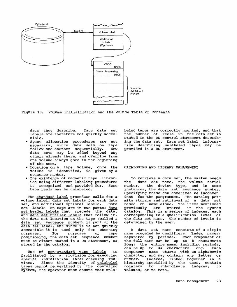
Figure 10 illustrates the contents of a direct-access volume after initialization. The volume label is at a fixed location, starting in track zero of cylinder zero.
: The user may specify up to seven additional labels for further identification. These will be located following the standard
. volume label.
The volume table of contents contains space for a series of data set control blocks, one for each data set to be written on the volume. Control blocks are also included to account for the space allocated to the table of contents itself, and to account for any space not yet allocated. At the time of initialization, all remaining space on the volume is available for allocation.
When a data set is to be created in direct-access storage, the steps are:
1. The volume specifications and data set name are given in a DD statement associated with the job step in which the writing operation will take place.
2. Allocation of space is requested, also by means of the DD statement.
3. When the job step is initiated, the system allocates space and creates a data set control block.
4. The OPEN and CLOSE functions, performed when the job step is being executed, complete the data set control block to reflect the characteristics and extent actually written.
MAGNETIC TAPE VOLUMES
The system controls magnetic tape volumes and identifies data sets residing on tape in a slightly different way from that used for direct-access volumes. This is due to several factors:
• Tape is serial, and data set labels on tape immediately precede and follow the
Cylinder 0
Track 0 ------i.-l Volume Label
Additional ) Labels
(Optional)
~
VTOC DSCB
Space Accounting DSCB
= Space for Additional DSCB'S
Figure 10. Volume Initialization and the Volume Table of Contents
data they describe. Tape data set labels are therefore not quickly accessible.
• Space allocation procedures are not necessary, since da1:a sets on tape follow one another sequentially. New data sets may be added beyond any others already there, and overflow from one volume always goes to the beginning of the next.
• Location on a tape volume, once the volume is identified, is given by a sequence number.
• The existence of magnetic tape libraries using different labeling procedures is recognized and provided for. Some tape reels may be unlabeled.
The standard label procedure calls for a volume label, data set labels for each data set, and additional optional labels. Data set labels on tape are in two parts: data set header labels that precede the data, and data set trailer labels that follow it. The data set location on the tape (called a data set sequence number) is part of the data set label, but since it is not quickly accessible it is used only for checking purposes. For purposes of tape positioning, the data set sequence number must be either stated in a DD statement, or stored in the catalog.
Use of non-standard tape labels is facilitated by a provision for executing special installation label-checking routines. Since the iden"ti ty of unlabeled tapes cannot be verified by the operating system, the operator must ensure that unla-
beled tapes are correctly mounted, and that the number of reels in the data set is stated in the DD control statement describing the data set. Data set label information describing unlabeled tapes may be provided in a DD statement.
CATALOGING AND LIBRARY MANAGEMENT
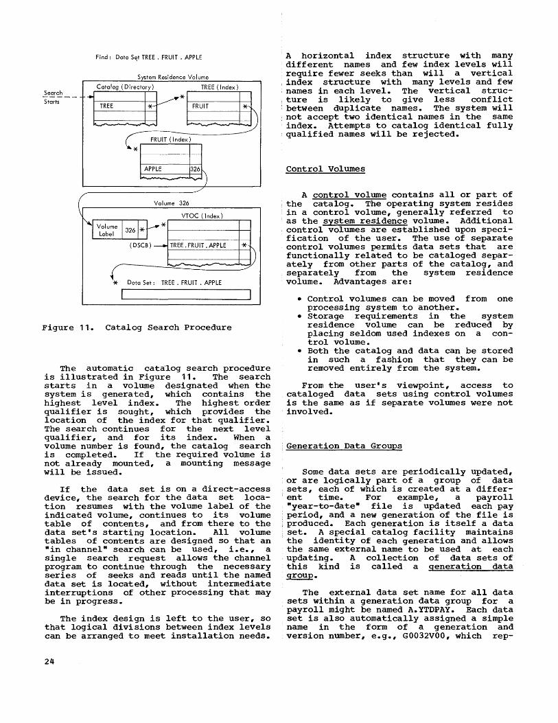
To retrieve a data set, the system needs the data set name, the volume serial number, the device type, and in some instances, the data set sequence number. Specifying these can sometimes be inconvenient for the programmer. The catalog permits storage and retrieval of a data set based on name alone. The items mentioned previously are stored in the system catalog. This is a series of indexes, each corresponding to a qualification level of the d~ta set name. The number of levels is determined by the user.
A data set name consists of a simple name preceded by qualifiers (index names) separated by periods. Each component of the full name can be up to 8 characters long; the entire name, including periods, can be up to 44 characters long. Each component name starts with an alphabetic character, and may contain any letter or number. Indexes, linked together in a hierarchy specified by the user, contain pointers to subordinate indexes, to volumes, or to both.
Data Management 23
Find: Data S~t TREE. FRUIT. APPLE
d V I 'ystem Resi ence o ume
Search -----Catalog (Directory) TREE (Index)
~* FRUIT
@ TREE *Y
~ ...... -
Starts
FRUIT ( Index)
* APPLE 326) -...,.
./
Volume 326
VTOC (Index)
~r Volume 1326 1* * Label
(DSCB) _ TREE. FRUIT. APPLE * ~-- -
* Data Set: TREE. FRUIT. APPLE
I I
Figure 11. Catalog Search Procedure
The automatic cata'log search procedure is illustrated in Figure 11. The search starts in a volume designated when the system is generated, which contains the highest level index. The highest order qualifier is sought, which provides the location of the index for that qualifier. The search continues for the next level qualifier, and for its index. When a volume number is found, the catalog search is completed. If the required volume is not already mounted, a mounting message will be issued.
If the data set is on a direct-access device, the search for the data set location resumes with the volume label of the indicated volume, continues to its volume table of contents, and from there to the data set's starting location. All volume tables of contents are designed so that an "in channel" search can be used, i.e., a single search request allows the channel program to continue through the necessary series of seeks and reads until the named data set is located, without intermediate interruptions of other processing that may be in progress.
The index design is left to the user, so that logical divisions between index levels can be arranged to meet installation needs.
24
A horizontal index structure with many different names and few index levels will require fewer seeks than will a vertical index structure with many levels and few
· names in each level. The vertical struc-· ture is likely to give less conflict
between duplicate names. The system will · not accept two identical names in the same index. Attempts to catalog identical fully qualified names will be rejected.
Control Volumes
A control volume contains all or part of the catalog. The operating system resides in a control volume, generally referred to as the system residence volume. Additional control volumes are established upon specification of the user. The use of separate control volumes permits data sets that are functionally related to be cataloged separately from other parts of the catalog, and separately from the system residence volume. Advantages are:
• Control volumes can be moved from one processing system to another.
• Storage requirements in the system residence volume can be reduced by placing seldom used indexes on a control volume.
• Both the catalog and data can be stored in such a fashion that they can be removed entirely from the system.
From the user's viewpoint, access to cataloged data sets using control volumes is the same as if separate volumes were not involved.
Generation Data Groups
Some data sets are periodically updated, or are logically part of a group of data sets, each of which is created at a different time. For example, a payroll ·year-to-date- file is updated each pay period, and a new generation of the file is
· produced. Each generation is itself a data set. A special catalog facility maintains the identity of each generation and allows the same external name to be used at each updating. A collection of data sets of this kind is called a generation data group.
The external data set name for all data sets within a generation data group for a
· payroll might be named A.YTDPAY. Each data set is also automatically assigned a simple name in the form of a generation and version number, e.g., G0032VOO, which rep-

resents generation 32, version zero. The next data set name which will be automatically assigned is G0033VOO. The external name qualifies the generation and version number. This automatic naming permits the user to refer to generations by either an absolute name, e.g., A.Y'TDPAY.G0032VOO; or by a relative name. An example of the relative notation is A.YTDPAY(O); this refers to the latest cataloged version. A .. YTDPAY (+1) identifies a. new data set to be added to the group, and A.YTDPAY(-1) identifies the next to the latest generation.
When the index for the generation data group is established, the programmer specifies how many generations he wants saved. If he wants a "grandfather, father, son" series maintained, he specifies three generations. As a new generation is cataloged, the oldest generation is either automatically destroyed, or it is merely deleted from the catalog.
Alternatively, the user may specify that all old generations of a full generation data group series be deleted from the catalog when the succeeding generation is added, so that the new ,entry effectively becomes the newest and only member of the series. This facility is useful in applications where several data sets are accumulated for a fixed period of time, then the entire set is processed and a new series started.
When. the generation data group index is established, a model da1ta set label is built for it. This model is used for each succeeding generation, to supply uniform attributes.
PASSWORD PROTECTION OF DA~[,A SETS
Most computer users have data sets that contain sensitive information, and want to restrict access to them. Examples of such records are payroll inforI~tion, corporate financial records, and the like. To safeguard such data, the system allows any data set to be flagged as "protected." This protection flag is tested by the control program as part of the OPEN macroinstruction routine. If the protection flag is on, a special handling procedure requires that a correct ~lssword be entered from the console. The password is appended to the data set name, which then serves as an argument for a search of a password data set. If a matching namE~-plus-password is found, the OPEN routine is permitted to continue. Reference to a flagged data set is not allowed by the system until the password is verified.
The password data set has its own ~ecurity flag and master password; thus it 1S secure against access except by the system supervisor program, when searching for a match, and by programmers knowing the master password. The password data set could be changed periodically to alter passwords for added security.
EDITING OF SPACE, INDEXES, AND CATALOGS
Operating System/360 users maintain data sets and the catalog by means of utility programs and system subroutines. These programs and subroutines can reorganize or edit volumes, data sets, and indexes.
Data sets may be deleted, or transferred from one volume to another, and fragmented volumes may be reorganized to consolidate available space. Data set names may be changed. New members may be added to a partitioned data set. Data sets may be cataloged or removed from the catalog; generation data groups may be established. Indexes of the catalog may be created or deleted, and the catalog may be reorganized. New control volumes may be established.
DATA ACCESS METHODS
System facilities are provided for retrieving and storing data once the data set has been located and is ready to be used in processing. When preparing a program, its designer must consider:
• The way data is arranged within the data set.
• The selection, where applicable, of one of the two categories of language statements, queued or basic, that indicate ~mong other things) whether input requirements may be anticipated, and output requirements deferred; or whether input and output are to be initiated as an immediate consequence of a language statement.
The combination of these two factors defines the access method. Each of the eight access methods has its features, from which the programmer can select those suited to the application.
The presentation of the data access methods is divided into two parts: a description of access methods and a description of blocking and buffering facilities.
Data Management 25
THE ACCESS METHODS
The first of the access methods to be described is the queued sequential access method (QSAM), the most widely used method in older input/output control systems.
Queued Sequential Access Method (QSAM)
The organization may be characterized as "tape-like," even when storage is on a direct-access device.
Logical records are retrieved by use of the GET macro-instruction, which supplies one logical data record (or a pointer to its starting location) to the program. The access method anticipates the need for records based on their sequential order, and normally will have the desired record in storage, ready for use, before the GET is issued. Logical records are designated for output by use of the PUT macroinstruction. The program normally can continue as if the data record were written immediately, although the access method's routines actually may perform blocking with other logical records, and the actual writing is performed after the output buffer has been filled. Since both GET and PUT rely on use of buffers supplied automatically, there may be a delay if computation gets ahead of the actual data transfer operations. This kind of delay is called an implied wait; its frequency of occurrence depends on many factors, including relative input/output and processing speeds, and total load on the input/output channels.
Basic Sequential Access Method (BSAffl
Data is sequentially organized. Physical blocks of data are dealt with rather than logical records. Input operations are initiated only when called for by a READ macro-instruction. The program may continue following a READ, before the data called for is retrieved. The user must specify when the data is required by using the CHECK macro-instruction, which in turn calls upon the wait function. Program execution is suspended at a CHECK until the retrieval is completed. In addition, a validity check of the retrieved record is made. Similarly, an output operation is initiated for each WRITE. The program may continue immediately following the WRITE, before the output operation is completed. To ensure that it was completed, the programmer must again use the CHECK macroinstruction.
26
Basic Partitioned Access Method (BPAM)
This method is designed for efficient storage and retrieval of sequences of data (members) belonging to a data set stored on
a direct-access device. Each member has a simple name. Included in the data set is a directory that relates the member name with the track address where the sequence starts. The FIND macro-instruction searches the directory for a simple name and prepares for gaining access to the associated member. Once a member is found it may be retrieved using successive READ macro-instructions; new members are written using successive WRITE's, followed by a STOW macro-instruction that updates the directory. Members may be added to a partitioned data set as long as there is space in the volume, and in the directory. CHECK is used to synchronize the program with the completion of each data transmission operation.
Indexed Sequential Access Methods - Basic and Queued (EISAM and QISAffl
Because of their complementary use of the indexed sequential data organization, BISAM and QISAM are discussed together.
With the indexed sequential organization, data records on direct-access storage devices are arranged in logical sequence on a data key. The data key will normally be a control field which is an intrinsic part of the information in the record (e.g., a part number); it may, however, be some arbitrary identifier associated with the record, such as a record serial number. When a record is stored, the data key is placed in a hardwaredefined key field associated with the record. (If records are blocked, then the highest data key in the block is placed in the key field.)
The data set also contains indexes relating the data keys of records to physical addresses. For the data set as a whole, there is a cylinder index that indicates the address of the cylinder on which a record with a given data key can be found. On each cylinder there is a track index that indicates the address of the track on which a record with a given data key can be found. On an optional basis, the cylinder index may be indexed by a higher level index.
To create the data set initially, QISAM is used in the "load mode." In this mode, successive PUT macro-instructions place the

records sequence) indexes.
(which must be in data key into the data set and create the
To retrieve records in sequential fashion, QISAM is used in the "scan mode.- In this mode, successivE~ GET macroinstructions retrieve logical records sequentially. A SETL (set lower limit) macro-instruction may specify the data key of the first record to bf:'! retrieved with a subsequent GET. If the GET macroinstruction is used without a prior SETL, retrieval starts at the beginning of the data set.
While in the scan mode~ the PUTX macroinstruction may be used following a GET to return an updated or replacement record to the data set, or to mask out an old record.
Selective reading is p,:!rformed by BISAM, using the READ macro-instruction, and specifying the key of the logical record to be retrieved. In this case, the entire physical block containing the logical record is read into storage, and the address of the specified logical record within that block is returned to the user's program. An indexed sf::'!quential data set can be updated in place, or new records inserted, by using BISAM and the WRITE macro-instruction. An important point is that BISAM is the only one of the basic access methods that can deal with logical records rather than blocks.
In the event that an intended insertion cannot fit in the available space on a track, one or more records on the track are automatically moved to an overflow area that may be on the same cylinder, on the same volume, or on a different volume. OVerflow records are indicated in the appropriate indexes.
The fact that some records are stored in overflow areas, physically out of sequence, does not change the ability of QISAM to read the data set in logical sequence as previously described.
A data control block for an indexed sequential data set can be opened for both QISAM and BISAM at the same time.
When using the READ or WRITE of BISAM, WAIT must be used to synchroni2e the program with the completion of the input/output transfer. Synchronization with QISAM is automatic.
In multitask environments, two or more concurrent tasks can refer to the same data set, or even the same logical record. In this environment, if the ·tasks use the same data control block, each program should request exclusive control of records while
they are being updated. In that way, records being updated by one task are not destroyed by the concurrent updating by another task.
Basic Direct-Access Method (BDAM)
This access method allows records within a data set to be organized on direct-access volumes in any manner chosen by the programmer. When a request to store or retrieve a record is made, an address either relative to the beginning of the data set or an actual address (i.e., device, cylinder, track, record position) must be furnished. This address can be specified as being the address of the desired record or as a starting point within the data set, where the search for the record begins. When a record search is specified, the programmer must also furnish the data key (e.g., part number, customer name) that is associated with the desired record.
When adding a new record to the data set, the address is used by the access method as a starting point at which to begin a search for available space. Thus the programmer doesn't have to keep track of available space within the data set. The extent of the search for available space (or record) can be controlled by the programmer.
The READ and WRITE macro-instructions are used to request data transfer. To determine if a request has been completed, the programmer must use the WAIT macroinstruction. When the WAIT has been satisfied (a record has been read or written), the status of the completion (e.g., no error, record not found) will also be available. There can be any number of READ or WRITE requests in effect at any one time.
Exclusive control of input records is available, as with BISAM.
Queued Telecommunications Access Method (QTAM)
Telecommunications devices have some characteristics that are significantly different from local input/output devices. For example:
• Remote terminals are not under positive control of the central processing unit, particularly when the data source is a keyboard. These factors complicate
Data Management 27

Monitoring of Telecommunications
Control C!f GET/PUT Record transmittal
QTAM Input --z--- Input
Enqueuer
I I I I I I
I QTAM I ...-z--- Output I Dequeuer
I Output
I I
I
QTAM Input
Dequeuer
Input Queue
QTAM Output
Enqueuer
Output Queue
User Program
------GET ------
User Program
------PUT ------
Figure 12. The Queued Telecommunications Access Method
error recovery procedures, and cause an unpredictable speed and sequence of input data.
• In some applications, messages of unpredictable length must be handled.
• The number of remote terminals may be very large relative to the number of local input/output units, such as tapes and disks.
Although the control of communications devices is considerably different from the control of local input/output equipment, the transmittal of data records between buffers and the user's program is much the same in both cases. This similarity allows the programmer to design processing programs for QTAM in much the same way as he would for QSAM, despite differences between telecommunications and local input/output devices.
The result of this, as illustrated in Figure 12, is that the programmer using GET and PUT does not deal at all with remote terminals: he deals instead with locally available queues of data records from which he may receive input, and to which he may add output.
28
Both input and output records are placed on queues specified by the programmer. The determination of which queue a record should be placed on may be influenced, for example, by the priority of the message, the receiving or transmitting terminal, and the identification of the processing routine. The sequence of records in each queue is based on their time of entry into the queue; the earliest record on an input (or "processing") queue is provided when data is requested from the queue by a GET. Similarly, messages are selected for transmission from output (or "destination") queues in the same sequence they were placed on the queue by a PUT.
In addition to buffer controls, many other message-related functions can be performed automatically by the QTAM programs, according to the programmer's specification. These functions are summarized as follows:
• Terminals sharing the same transmission line are addressed and polled, to permit contention for line use on a controlled basis.
• Message headers are analyzed to deter-

mine where messages are to be routed. Routing of an incoming message may be to another terminal, or to a group of terminals. Some may be routed to a processing queue, from which they will be moved with a subsequent GET.
• Automatic functions are available, such as queueing, checking the sequence number of incoming messages, assigning a transmission sequence number to outgoing messages, validating source and destination codes, logging, translating between external transmission code and internal processor code, checking for transmission errors and taking corrective action, and placing the date and time of day in messages for control purposes.
A telecommunications language, based on the operating system assembler, allows a programmer to specify these functions in convenient problem-oriented terms.
Basic Telecommunications Access Method (BTAM)
The same polling and line control fUnctions of QTAM are provided in BTAM. The READ and WRITE macro-ins·tructions are used to request data transmission; the WAIT macro-instruction is used to synchronize program execution with data transmission.
BLOCKING AND BUFFERING FACILITIES
Because of the similarity in block formats and buffering facilities in many of the access methods, these topics are described separately rather than being repeated in the discussion of each access method. To assist the reader furt,her, a summary of the access methods is pr'esented in a foldout chart (Table 1) that may be kept open. The chart associates the features discussed with the access methods in which they are used.
Block Formats
Data blocks (i.e., physical records with hardware-defined boundaries) that are stored on external storage devices may have any of three different formats: fixed (~, variable W), or unspecified (U). In all cases, a maximum length must be specified in advance. The size of blocks with the F format is normally equal to the maximum length; the size of blocks with the V
format is unpredictable but is specified in a count field at the beginning of each block; the size of blocks with the U format is also unpredictable, but there is no corresponding count field.
Format F and V data blocks may contain blocked logical records. If so, the logical records in the F format are all of a fixed Size, and normally, the same number of records appears in each block. The logical records in the V format may be of different sizes; each must be preceded by a length field specifying the record size. Normally, a V format block contains the largest number of records that can fit within the specified maximum size.
Blocks that are shorter than the maximum may be deliberately created. Such blocks will be properly handled when subsequently read.
Data formats used in the telecommunications access methods are necessarily different from those described thus far. A message is that unit of text that is terminated by a special Rend-of-message n text character or set of characters (depicted by nEOMn in Figure 13). A block is a portion of a message terminated by a special nend-of-blockn text character or set of characters (depicted by nEOB n in Figure 13). An e~ception is the last block of a message which need not have the end-of-block characters. A segment is that portion of a message contained in a buffer, the size of which is specified by the user. As shown in Figure 13, a message is divided into segments without reference to the length of its blocks.
Records for BTAM consist of blocks; records for QTAM can be either messages, blocks, or segments.
~- Message
Segment I Segment I (1) (2)
Segment I Segment (3) (4)
:;~i~:ting -1 ! I [ I ! I I Block (1) 1 Block (2)
EOB
1 Block (3) 1 EOB EOM
Figure 13. Components of a Message
Data Management 29

Buffering Facilities
A buffer, as described in this manual, is the area of main storage used for data that is being transmitted between main storage and an external medium. When using the basic access methods, individual buffers need not be identified to the control program before a READ or WRITE macroinstruction is issued; when using the queued access method, more buffer space is generally required, and it is required in advance of the GET and PUT to permit automatic overlap of reading, writing, and processing. As a result of these differences, the buffer facilities available for the basic access methods are relatively simple; those available for the queued access methods, are more numerous and flexible.
Three aspects of buffering facilities are discussed in the following paragraphs:
• Buffer pools the means by which storage may be set aside and initialized for use as buffers.
• Buffer assignment techniques - the selection of particular buffers from the pool.
• Transmittal modes - the manner in which a buffer routine and the using program -transmit n the buffer contents to each other.
Buffer Pools
A buffer pool is assigned to specific data control blocks (DCB's). A data control block is a region in storage used for communication between the user's program, the control program, and the access routines. (The method of creating the data control block and its role in the system are described later. For now, it is sufficient to point out that the only way to obtain access to a data set is by reference to a data control block.)
Before space in a buffer pool is used for buffers, information describing the size and number of buffers is stored in the pool area. This is called constructing the buffer pool. The programmer may assign and construct buffer pools in three different ways. The first method is to define a buffer area when the program is assembled. The structure is created when the program is executed, using the BUILD macroinstruction. This method allows the buffer pool to be assigned to more than one data control block, and thus be available for processing more than one data set at a time.
30
The second method is to use the GETPOOL macro-instruction which obtains main storage space dynamically, and performs the functions of BUILD.
The third method is to let the system perform both the buffer area allocation and buffer structuring automatically, as part of the OPEN operation.
A special macro-instruction (BUFFER) is available for use with QTAM to do much the same thing as GETPOOL. However, the structure of the buffer pool obtained by BUFFER is tailored for the unique requirements of QTAM. The size of each buffer, specified by the user, determines the size of a nmessage segment. n
Buffer Assignment Techniques and Transmittal Modes
The assignment techniques and transmittal modes are discussed as they pertain to basic or queued access methods.
BASIC ACCESS METHODS: In all basic access methods, buffers are controlled by the programmer. He may obtain and return pooled buffer space using the GETBUF and FREEBUF macro-instructions; or he may use storage areas that are not in any pool. The only requirement (normally) is that he specify the buffer to be used as part of each READ or WRITE macro-instruction.
Since he controls the buffer, input buffers are available as work areas after completion of the READ operation; output buffers are available as work areas prior to the execution of the WRITE operation.
Some access methods permit multiple READ requests to be queued. In such cases, each request may be assigned a buffer dynamically, just before the transfer of data begins. To conserve main storage, this option should be used whenever multiple READ requests are common and the processing time for each record is short.
For example, it may be sufficient to use a buffer pool containing only 4 buffers, even though 15 READ requests are normally on the queue ~igure 14). At a typical pOint, 1 buffer (A) may be available in the buffer.pool, 2 may be in use as work areas (C and D) , and only 1 -- not 15 -- would be
assigned to the queue for the input operation in process (B). Buffers obtained dynamically, after their use as work areas, may be returned to the pool with either a WRITE or a free dynamic buffer (FREEDBUF) macro-instruction.

QUEUED ACCESS METHODS: With the queued access methods, all control over buffers is made automatic, to ensurE~ overlap between input, output, and processing.
There are two closely related aspects of queued access buffer management that need to be taken into account to make most effective use of buffers. Both relate to how frequently data must be moved after its initial entry or creation in main storage. For example, input data records may be:
2
3
4
15
• Moved from the buffer to a user work area.
• Worked on while still in the buffer area.
Queue of I Buffer READ Requests I Pool
~, I
,I ~ A
I I \ I \ ~ \ B wai I \
I \ \
I ~~ c • J • I • • 1 D ~
I I I
Figure 14. Dynamic Buffering
Or, if the input records are also to be used as output, possibly after some modification, they may be:
• Moved from the input: buffer to a work area, and from the work area to the output buffer.
• Worked on while sti.ll in the input buffer and then moved to the output buffer.
.. Worked on while sti.ll in the input buffer and then be the output from that same buffer.
The two aspects of buffer management that affect the movement of data within main storage are transm~ttal modes and buffer techniques.
Transmittal modes by which input data in
refer to the options a buffer is made
available to the user program; or by which output data created by the user program can be placed in a buffer for output.
To accomplish these functions, three transmittal modes are defined~:
• Move Mode The GET jand PUT macro-instructions transfer data from an input buffer to a work area, and from a work area to an output buffer.
• Locate Mode - GET and PUT do not move data, but provide a pointer to a record location in a buffer.
• Substitute Mode - Similar to the locate mode, except that the programmer must provide a storage area equal in size to the buffer that is being pointed to. The storage area is exchanged for a buffer segment. The buffer and work area, in effect, change roles.
Buffer techniques refer to the various ways in which the control program can allocate buffers from the pool for use in input/output operations. Depending on the access method, a number of automatic buffering techniques are available, as shown in Table 1.
Simple buffering, technique, uses one each data set, each maximum length block.
the most flexible or more buffers for long enough for a
Exchange buffering, is used with two data control blocks, one associated with an input data set, the other with an output data set. Control is by buffer segment, with each segment holding a logical record. Data need not be moved in storage; instead the control of each buffer segment may be treated, in turn, as an input area, work area, and output area. Data chaining is used to allow noncontiguous segments to be treated as blocks. Buffer segments are fixed in length, so that any record length changes must stay within the preplanned length.
Chained segment buffering accomodates messages of variable sizes. Since a message will normally not fit into a single segment, segments are assigned dynamically, during data transfer. Address chaining techniques are used to relate physically separated 'segments. In this way, the amount of main storage in use for buffers is controlled by the system, and buffer space is used effectively for all transmission, rather than being allocated on a fixed basis to lines or terminals not in operation at the moment.
As described in the detailed publications, only certain combinations of transmittal modes and buffering techniques are used. Here, illustrations will be given of
Data Management 31

Input Buffers OutPl-'t Buffers
B
Figure 15. Simple Buffering - Move Mode
only the most common combinations, where input and output data sets are controlled as follows:
INPUT simple, move simple, locate exchange, substitute
OUTPUT simple, move simple, move exchange, sUbstitute
SIMPLE BUFFERING, MOVE MODE: Simple buffering for an input data set with three logical records in one block is illustrated in Figure 15. Data is moved to a work area large enough for one logical record. Each logical record, after processing, is moved to an output buffer, and a new (updated) data set is written. Overlapping of input and output operations is achieved by having two buffer areas for each data set, as illustrated. Simultaneously: 1) input buffer A is filled. 2) logical records are moved from input buffer B to the work area, and then to output buffer A. 3) the contents of output buffer B are being written out. The roles of input buffers A and B are alternated; the roles of output buffers are alternated also.
This type of simple buffering is the most flexible kind of processing, but is not always the fastest, because two moves are required. Movement of data from an input buffer to the work area is requested by the move mode GET, and to the output buffer by the move mode PUT.
SIMPLE BUFFER-LOCATE MODE INPUT, MOVE MODE OUTPUT: In applications where processing does not increase the length of a logical record, it is practical to process data while it is still in an input buffer. In this case, the locate mode of GET is used, and time is saved because only one move is
32
A
needed. The PUT or PUTX macro-instructions are used to move logical records from the input buffer directly to the output buffer. Insertion and deletion of records are allowed. This technique is illustrated in Figure 16.
Input Buffers Output Buffers
,I .--In-put-~: I ~ Output :> ._p_u_~_~_ro:_~_~_x_._ I GET (Locate)
Figure 16. Simple Buffering - Locate Mode
EXCHANGE BUFFERING-SUBSTITUTE MODE: This method is especially applicable for fixed length records where insertions and deletions are expected. Exchange buffering with the substitute mode is illustrated in Figure 17. The illustration shows the status of 12 buffer segments (corresponding to 4 blocks of 3 logical records each) and an original work area after 100 cycles of operation. By now the physical location of the buffer segments (labeled A-L) is totally unrelated to the records (101-108) they contain. A set of tables (at the bottom of the figur~ indicates the current usage of
THE SEGMENt'S.
In the example, E, D, and I are in use for input (the only input so far has been record 108); and G, A, and C containing records 101-103 are in use for output. Record 104, in area H has been processed;

Record Storage Area
~ _'OP"' :> Original Work Area
1M
'\
:~ GET (Subs)
M ¢ L D 106 F
I 107 K PUT (Subs)
Current Process "-Input Input Work Area Block List Pointer
104 H
J B
Process Output List
Output ~ ----'----V
.... 101
102
103
Current Output Block
G A
C
Figure 17. Exchange Buffering - Substitute Mode
record 105 in area L is being processed, and will be placed (lo9ically, but not physically moved) by the PUT substitute mode in the output buffer.. The PUT exchanges pOinters Land J. Following that, the next GET will exchange pointers J and F.
THE DATA CONTROL BLOCK
The data control block and the procedure by which it is initialized provide the key to the system's data handling flexibility. It is by means of the ini"tialization procedure caused by the OPEN macro-instruction that many of the specifications needed for input/output operations, in particular those dealing with device identification and buffer sizes, can be made when the job is to be executed rathe:r- than at the time the program is written.
OPEN AND CLOSE MACRO-INSTRUCTIONS
Each data set to be di:rectly referred to by a problem program is associated with a data control block that must be initial;ized (opened) before any data transfer takes place and suitably modified (closed) after all data transfer is completed. Under certain circumstances the same opened data control block may be used to control access
to a number of different data sets1 and a data set may be referred to through several concurrently open data control blocks. Nevertheless, when there is no ambiguity, it is often convenient to talk of opening and cloSing a data set (rather than the associated control block). Data access statements in a program, such as GET and PUT, also logically refer to a data set even though their actual reference is also to the control block.
Some data sets are opened automatically by the control program, and may be indirectly referred to or used in a problem program without additional opening or closing. One example is the catalog data set.
The OPEN routine, at the time of its execution, has three primary functions:
• It completes the data control block. • It ensures that all needed access rou
tines are loaded, and necessary address relations completed.
• It initializes data sets by reading or writing labels, and performs other related housekeeping operations.
The data control block is created when the program is compiled, even though all of its fields may not be filled in at that time.
Information from two additional sources is used by the OPEN routines. These sources and the fill-in sequence of the control
Data Management 33

block are illustrated in Figure 18. The first is the source program itself. Any parameter stated in the source program DCB macro-instruction (which contains only nonexecutable data) is used. In general, only those DCB macro-instruction parameters should be stated in the source program that are needed to ensure correct program operation. Other parameters should be omitted, to allow for filling in from one or the other of the two remaining sources when the job is to be executed. In the illustration, A is filled first when the program is compiled.
DeB Macro DD Statement Data Set Label
A e D
o
DeB Area
A
DeB Fill-In at OPEN
Figure 18. Data Control Block Being Filled In
The second source of data control block fields is the DD statement from either the input job stream or from a cataloged procedure called upon by an EXEC statement in the input job stream.
In the illustration, Band C are stated in the DD statement but only B is used, since the third field, the intended destination for C, is already filled with A.
The third source is a data set label. Label fields are used to fill in any fields still blank after the first two sources have been used. For data sets being read, the actua~ data set label information is used. For data sets being created, a nmodel" can be designated. The model can be the label of some data set already in the library, or it can be a different DD statement in the same job step. In the example, the second field is filled from the data set label.
34
This procedure permits full flexibility to change data control block fields at job time, without requiring that all DCB macroinstruction parameters be restated each time a job is run. These macro-instruction parameters and possible sources for each are given in the publication, IBM Operating System/360: Control Program Services.
Each data set's data control block should be closed after use. The CLOSE macro-instruction restores a data control block to its original condition, so that it may be reused in the same program for a different data set. The closing operation also writes the trailer label on tape, or completes the data set control block for direct-access storage. In the event any data control block is still open when the task is terminated, the system performs the CLOSE functions automatically.
DATA ACCESS ROUTINES
After all data control block fields have been filled in, the next step is to ensure that all access method routines are loaded and ready for use, and that all channel command word (CC~ lists and buffer areas are ready, if the access method requires them.
The selection and loading of the access method routines is made according to data control block fields that tell the data organization, buffering technique, access language features to be used, input/output unit characteristics, and other factors. The identification of all needed access routines is relayed to the supervisor, which allocates main storage space and loads them into main storage. They remain there until the CLOSE routine signals that they are no longer in use by that data control block. Access routines are written so that the same copy may be shared by all programs in the system that need them. Sharing may be between two data sets within one program, between two independent tasks, and between the user's programs and the control programs.
The access routines are treated as if they were a part of the user's program, and are entered directly rather than through a supervisor call interruption. The routines block and deblock records, control buffers, and communicate with the input/output supervisor when a request for data input or output is needed. The input/output supervisor, part of the supervisor nucleus, performs all actual device control. It accepts all input/output requests, queues them if necessary, and issues them whenever a path to the desired input/output unit is
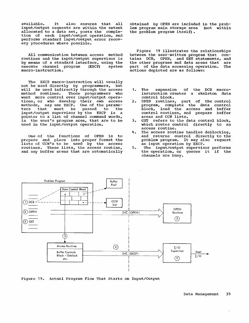
available. It also e:nsures that all input/output requests are '~ithin the extent allocated to a data set, posts the completion of each input/output operation, and performs standard input/output error recovery procedures where possible.
All communication between access method routines and the input/output supervisor is by means of a standard interface, using the execute channel program (EXCP) system macro-instruction.
The EXCP macro-instruction will usually not be used directly by programmers, but will be used indirectly through the access method routines. Those programmers who want more control over input/output operations, or who develop their own access methods, may use EXCP. One of the parameters that must be passed to . the input/output supervisor by the EXCP is a pointer to a list of channel command words, in the user's program area, that are to be used in the input/output operation.
One of the functions of OPEN is to prepare and place into proper format the lists of CCW's to be used by the access routines. These lists, the access routine, and any buffer areas that are automatically
Problem Program I Pool I I ./ Data Control BI~Ck __ --.... I
/,,/// 1 1.- - -- :
CDDCBL~:------ 11 11 .. _____ ~ I -- ~ I
obtained by OPEN are included in the problem program main storage area (not within -the problem program itself) •
Figure 19 illustrates the relationships between the user-written program that con...:. ·tains DCB, OPEN, and GET statements, and ·the other programs and data areas that are part of the data accessing operation. The actions depicted are as follows:
1. The expansion of the DCB macroinstruction creates a skeleton data control block.
2. OPEN routines, part of the control program, complete the data control block, load the access and buffer control routines, and prepare buffer areas and CCW lists.
3. GET refers to the data control block, which routes control directly to an access routine.
4. The access routine handles deblocking, and returns control directly to the problem program. It may also request an input operation by EXCP.
5. The input/output supervisor performs the operation, or queues it if the channels are busy.
®OPEN ____ -r ________ ~----------s~v~c~:(O~P-EN~)------~~ OPEN
Routines
®GET
cp Access Routines
Buffer Controls Block - Deblock
etc _
0
I I I I I I I I ~
r-_____________ s_VC_rl(E_XC_P~) ______ ~v/ 1 I
Figure 19. Actual Program Flow That Starts on Input/Output
I/O Supervisor Start
I/O
Data Management 35
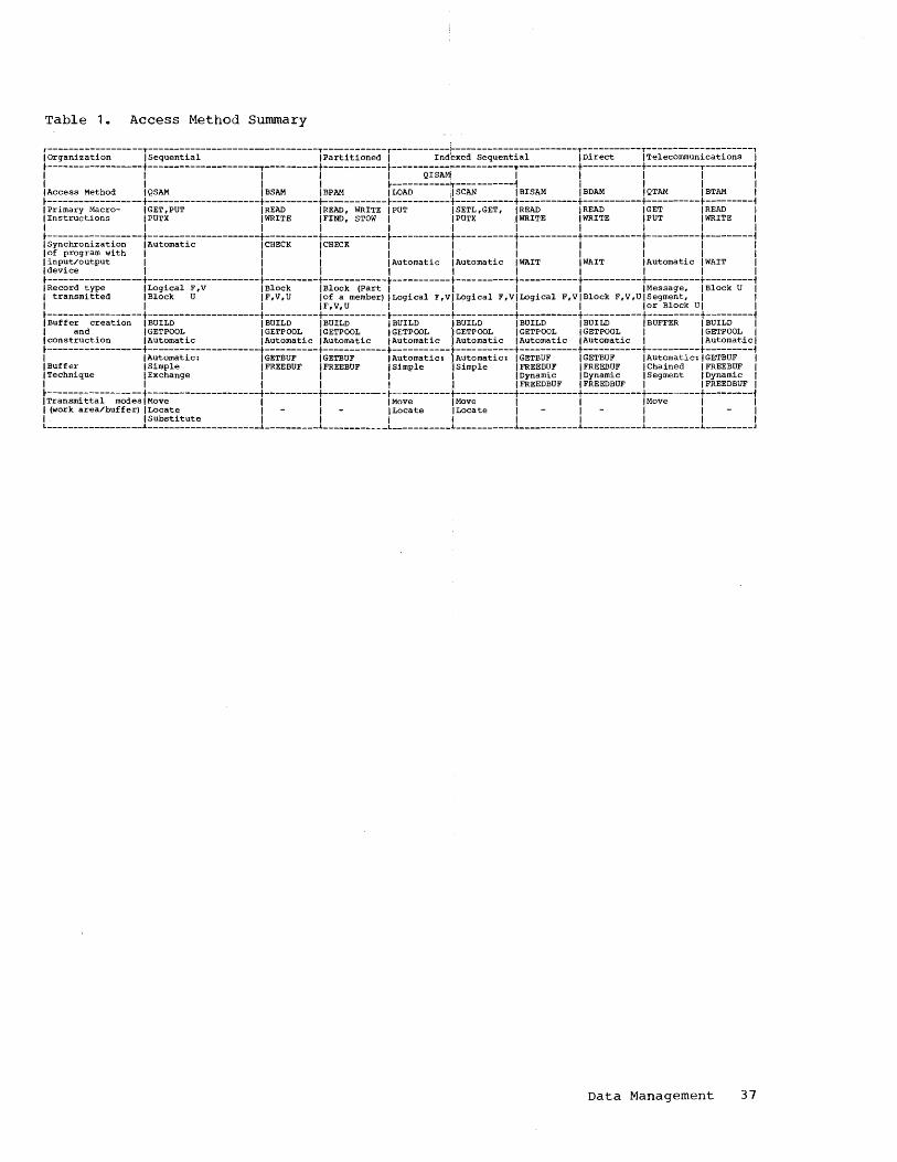
Table 1. Access Method Summary
r------------------T--------------------------------T-----------"r-----------;..-----------------------T-----------T-------------------, I Organization I Sequential IPartitioned I Indexed Sequential I Direct I Telecommunications I t-----------------t---------------------T----------t----------- t----------------------T-----------t-----------t----------T--------~ I I I I I QISAMI I I I I I I I I I t-----------T-----------~ I I I I I Access Method I QSAM I BSAM I BPAM I LOAD I SCAN I BISAM I BDAM I QTAM I BTAM I t------------------t---------------------t----------+----------- t-----------t---- -------t-----------t----------t----------t--------~ I Primary Macro- I GET, PUT I READ I READ, WRITE I PUT I SETL, GET, I READ I READ I GET I READ I I Instructions IPUTX I WRITE I FIND, STOW I I PUT X I WRITE I WRITE IPUT I WRITE I I I I I I I I I I I I t------------------t---------------------t----------t----------- t-----------t-----------t-----------t----------t----------t---------~ I Synchronization I Automatic I CHECK I CHECK I I I I I I I lof program with I I I I I I I I I I I input/output I I I I Automatic I Automatic I WAIT I WAIT I Automatic I WAIT I I device I I I I I I I I I I t-----------------t---------------------t----------t------------l-----------t-----------t-----------t-----------t----------t----------f IRecord type ILogical F,V I Block IBlock (Part I I I I IMessage, IBlock U I I transmitted I Block U IF,V,U lof a member) 1 Logical F,VILogical F,VILogical F,VIBlock F,V,UISegment, I I I I I IF, V, U II I I lor Block U I I t------------------t---------------------t----------t----------- t-----------t-----------t-----------t-----------t----------t----------f I Buffer creation I BUILD I BUILD I BUILD I BUILD I BUILD I BUILD I BUILD I BUFFER I BUILD I I and IGETPOOL IGETPOOL IGETPOOL IGETPOOL IGETPOOL IGETPOOL I GET POOL I IGETPOOL I I construction I Automatic I Automatic I Automatic I Automatic I Automatic I Automatic I Automatic I I Automatic I t-----------------t---------------------t----------t----------- ... -----------+-----------t-----------... -----------t---------t----------f I I Automatic: IGETBUF IGETBUF I Automatic: "I Automatic: IGETBUF IGETBUF 1 Automatic; IGETBUF I I Buffer I Simple IFREEBUF IFREEBUF I Simple I Simple IFREEBUF IFREEBUF 1 Chained IFREEBUF I I Technique I Exchange I I I I I Dynamic I Dynamic I Segment I Dynamic I I I I I I I IFREEDBUF IFREEDBUF I IFREEDBUF I t------------------t---------------------t----------t---------- - t-----------t-----------t-----------t-----------t---------t---------f I Transmi ttal modes I Move I I I Move I Move I I I Move I I I (work area/buffer) ILocate I I 1 Locate 1 Locate I I I I I I I Substi tute I I I I I I I I I L __________________ .1. _____________________ .1. _________ .1. ___________ L ___________ .1. ___________ .1. ___________ .1. ___________ .1. __________ .1. ________ J
Data Management 37

Operating System/360 provides a number of facilities to the programmer for his assistance in planning and coding a p:t'o<,fram. This section describes the var10US techniques that the programmer may use in constructing his program, and special features he may request in his coding by means of assembler language macroinstructions. (Some of 'the features are also available to use:rs of compiler languages.) Also described is the flow of control at the time these macroinstructions are executed.
PROGRAM SEGMENTATION
Techniques for designing large programs as smaller, more easily managed subprograms have been used for many years. There are many advantages in doing this. For instance: large programming jobs can be assigned to several diffe:rent programmers; common subroutines can he reused; program testing and maintenance a:re simplified; and each subprogram can be written in ,the source language that is most appropriate. Operating System/360 adds a new dimension to the flexibility availal?le in program design. Now subprograms may be combined at four distinct times during the cycle from program statement to complete job execution:
• Compilation or Assembly Time. Sub;r:outines and separately written sohrce decks may be combined as the input to a single compilation or assembly.
• Linkage Editing Time. Separately compiled object modules and load modules can be included as the input to a single linkage editor run, to produce a single composite load module for execution. If overlay techniques are used, the entire load module need not be contained in available main storage.
• Job Entry Time. Load modules that correspond to phases of a multiphase procedure can be specified in EXEC statements as individual job steps. Interconnection and interstep dependencies are handled by the job scheduler. By segmenting a procedure in this way, the greatest economy is obtained in the allocation of space on direct-access devices. Only the space required for one step of the procedure need be assigned at one time.
• Task Performance Time. The load module named in an EXEC statement, or in
SECTION 4: PROGRAM DESIGN AND PREPARATION
general, the first load module used in the performance of any task, may interconnect with other load modules named during the time the task is performed. Modules are placed wherever storage is available, relocated, (i.e., initialized to execute from a chosen location) and interconnected dynamically. Overlay of entire load modules may take place, and individual load modules may sometimes be shared between different tasks in a multitask operating environment.
The same sequence of instructions, in the appropriate one of its three forms of source, object, or load module, can be used with little or no change at any of the specified times as a subprogram of a larger sequence of instructions.
PROGRAM STRUCTURES
When a new task is created, the control program is given the name of the first load module to be executed. The named load module may (but needn't) be loaded into main storage in one operation; and it may (but needn't) be interconnected with other load modules in the course of the task's performance. Depending on the programmer's choice, the code executed on behalf of a task -- in this context, a program can be categorized as one (or a combination) of the following program structures:
1. Simple Structure. A single load module contains all of the user code required for task performance and is loaded into main storage as an entity. It is immaterial whether the load module may itself have been derived from other load modules as a result of the linkage editor run, or whether other load modules may be employed as a result of requests for supervisor services.
2. Planned Overlay Structure. In this case, the required code is processed by the linkage editor into a single load module, just as with programs having simple structures. The only difference is that all sections of the load module are not loaded at the same time. Instead, segments of the program are identified which need not be in main storage at the same time. The same area of main storage is used and reused by different program segments.
Program Design and Preparation 39

3. Dynamic Serial Structure. More than one load module is called upon during the course of program execution. All linkages follow standard linkage conventions, with the control program acting as an intermediary in setting up subprogram entry and return. Program execution is serial, which is the same as in types 1. and 2.
4. Dynamic Parallel Structure. More than one load module is called upon during the course of program execution, and the supervisor is an intermediary just as in type 3. In this case, however, the execution of two or more subprograms is allowed to proceed in parallel. To accomplish this, each asynchronously operating subprogram is established as a task and follows normal task rules.
Most programmers preparing programs to run under Operating System/360 will not be concerned with all of the variations possible in program segmentation and program flow. The operating system is designed to handle programs that use few or many of the variations, either in a single-task or a multi task environment. The following paragraphs discuss more fully the program design approaches available to the programmer.
SIMPLE STRUCTURES
Figure 20 ,illustrates a simple program structure. A task has been attached with the specification that the first load module to be executed is SIMPLE. The supervisor finds SIMPLE, allocates space for it, and then loads the entire load module prior to execution. The name SIMPLE designates not only the entire set of code contained in the load module, but also the particular entry point to be used.
SIMPLE
---.... SIMPLE SAVE
_-----+-RETURN
Figure 20. Execution of a Load Within a Task
40
Module
The same load module may be associated with a number of different program names, each of which can correspond to a different entry point. At linkage editing time, a primary program name and up to five aliases may be specified. All names and the corresponding entry points are contained in the directory of the library in which the load module is stored. In addition, a load module can dynamically specify additional names and entry points. These are not retained when the space used by the load module is released.
In the example, when SIMPLE completes its execution, it notifies the supervisor by the system macro-instruction RETURN. At the same time, it places in a standard register a return code, by which it reports
using conventions established by the user -- how it was completed: -normally,-type X condition encountered-, -type Y condition encountered,n and so on. The supervisor, recognizing that SIMPLE is the only load module required by the task, will then terminate the task.
SIMPLE is written so that it could also be used as a subprogram of a larger program, either one formed by the linkage editor with SIMPLE as an input, or in a dynamic structure. It begins with a SAVE macro-instruction that expands to an instruction sequence that saves designated registers. The RETURN macro-instruction, in addition to setting the return code register, restores the saved registers. If there had been a higher level program, control would then have been passed back to it.
SIMPLE itself may be a composite of several load modules that have been combined into a single load module by the linkage editor, as shown in Figure 21. This does not change the fact that SIMPLE is a program with a simple structure (since it is, at execution time, a single load module, all of which is in main storage) •
SIMPLE User's Program Area
--t--... SAVE SUBPROG SAVE
CALL SU'PROG /
RETURN +--1- RETURN
Figure 21. Subprogram Within a Program

In the figure, two subprograms are shown, the first calling upon the second named SUBPROG. By definition the calling subprogram is at a higher control level than the called sUbprogram. In this example, the supervisor is not involved in the subroutine linkage. The reference between CALL SUBPROG and the address SUBPROG is resolved as part of the linkage editor process. The RETURN in SUBPROG restores the registers and branches to the higher control level. The supervisor is not called. Internal linkages of this sort are more efficient in terms of execution speed than are linkages where the supervisor is involved.
Within the logical flow of a simplestructured load module, other load modules may actually be called upon indirectly as supervisor services. This can take place indirectly as a result of a request for supervisory service, or in a slightly different way, as with the input/output and buffer control routines described in Section 3. In the latter case, the OPEN function incorporates additional load modules as if they were logically part of the same simple logical flow of the single load module. Linkage to such added load modules is made via the data control block. The routines are thus used directly, without any supervisor ac·tion, except when a hardware input/output operation is actually required.
Note that the sequences of code, lines and arrows in this and other figures in this section denote logical flow, not actual flow. That is, hardware interruptions may cause an actual flow quite different from the flow that the programmer plans. Actual flow, described later in "Task Management,· Sect:ion 6, is not a matter of concern to the programmer when he designs his program.
Deferred Exits
Figure 21 showed how a. subroutine may be entered at a predictable point in the logical flow of a load module. There are some situations where the exit point may not be known in advance, but depends on an interruption whose time of occurrence is unpredictable. Such subroutines may nevertheless be included by the linkage editor in a load module. Included also must be system macro-instructions that the programmer uses to describe the conditions for entry into the subroutines, as well as their entry points.
Four conditions achieve a deferred logical flow:
may be specified to exit from the main
1. Completion of a timing interval. 2. Program error interruptions. 3. Unusual end of task. 4. End of subtask.
Completion of a timing interval by use of the STIMER macro-instruction, the processing time used by anyone task (which may be significantly less than total elapsed time) may be measured. For example, the programmer may request notification after one second of task time. such an interval may be set up just prior to entering a possibly endless loop in a program under test. As a parameter of the macroinstruction, the programmer specifies the entry point in the current load module to be entered after the specified time expires. Thus, if the program overstays its alloted time in the loop, control is passed to a routine that can take corrective "action. If an exit is made from the loop before the time interval expires, the TTIMER macro-instruction may be used to cancel the interruption request. A further discussion of the interval timer functions appears later in this section.
Program error exits are requested by the set program interrupt exit (SPIE) macroinstruction. The programmer may specify the types of program interruptions his subroutine will handle, and the types the supervisor is to handle. The programmer most likely will want to handle conditions such as overflow and underflow from arithmetic operations, and let the supervisor take normal action for the others, such as execution of a privileged instruction and violation of storage protection.
An abnormal end of task exit is set up by the specify task abnormal exit (STAE) macro-instruction. This exit is taken if the task is abnormally terminated internally or externally. An internal termination is one resulting from the execution of the abnormal end of task (ABEND) macroinstruction. This may be issued by the user's program after the determination is made that an uncorrectable error has occurred. An external termination is one initiated by the supervisor program, for example, in the event of storage protection violation or the expiration of the specified time for the job step.
End of subtask. In multitask operations, the completion of any subtask can cause an entry into a specified point in the program of the higher level task.
An example of a deferred exit is shown in Figure 22. In this case, a subroutine named FIXUP is to be entered in case of floating-point overflow. The SPIE macroinstruction specifies the exit condition, namely, floating-point overflow. At the
Program Design and Preparation 41
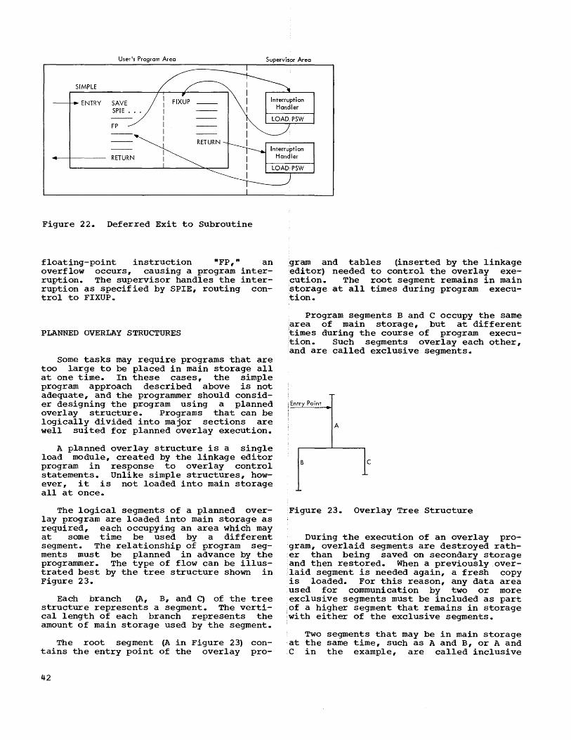
User's Program Area Supervisor Area
SIMPLE
ENTRY SAVE SPIE •••
Interruption Handler
FP
RETURN
RETURN Interruption
Handler
Figure 22. Deferred Exit to Subroutine
floating-point instruction ftFP,· an overflow occurs, causing a program interruption. The supervisor handles the interruption as specified by SPIE, routing control to FIXUP.
PLANNED OVERLAY STRUCTURES
Some tasks may require programs that are too large to be placed in main storage all at one time. In these cases, the simple program approach described above is not adequate, and the programmer should consider designing the program using a planned overlay structure. Programs that can be logically divided into major sections are well suited for planned overlay execution.
A planned overlay structure is a single load module, created by the linkage editor program in response to overlay control statements. Unlike simple structures, however, it is not loaded into main storage all at once.
The logical segments of a planned overlay program are loaded into main storage as required, each occupying an area which may at some time be used by a different segment. The relationship of program segments must be planned in advance by the programmer. The type of flow can be illustrated best by the tree structure shown in Figure 23.
Each branch (A, B, and C) of the tree structure represents a segment. The vertical length of each branch represents the amount of main storage used by the segment.
The root segment (A in Figure 23) tains the entry point of the overlay
42
conpro-
,gram and tables (inserted by the linkage editor) needed to control the overlay execution. The root segment remains in main storage at all times during program execution.
Program segments Band C occupy the same ,area of main storage, but at different 'times during the course of program execu,tion. Such segments overlay each other, ;and are called exclusive segments.
j Entry Point ~
A
Figure 23. Overlay Tree Structure
During the execution of an overlay program, overlaid segments are destroyed rather than being saved on secondary storage and then restored. When a previously overlaid segment is needed again, a fresh copy :is loaded. For this reason, any data area used for communication by two or more exclusive segments must be included as part of a higher segment that remains in storage 'with either of the exclusive segments.
Two segments that may be in main storage at the same time, such as A and B, or A and C in the example, are called inclusive
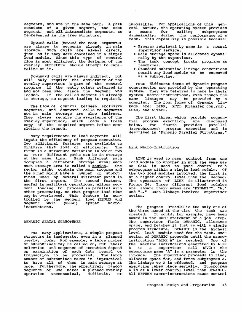
segments, and are in the same path. A path consists of a given segment, the root segment, and all interm,ediate segments, as represented in the tree structure.
Upward calls (toward ·the root segments)· are always to segments already in main storage. Such calls a:re always direct, just as if they were contained in a simple load module. Since this type of control flow is most efficient, ·the designer of the overlay structure should attempt to capitalize on it.
Downward calls are always indirect, but will only require the assistance of the overlay supervisor (a part of the control program) if the entry points referred to had not been used since the segment was loaded. If the called segment is already in storage, no segment loading is required.
The flow of control between exclusive segments, and downward calls to segments not in main storage are also indirect. 'l~hey always require the assistance of the overlay supervisor, which loads a fresh copy of the required segment before completing the branch.
Many requirements to load segments will impair the efficiency of program execution. Two additional features are available to m1n1mize this loss of efficiency. The first is a structure variation in which two or more different paths can be in storage at the same time. Each different path occupies a different storage area; each such storage area is called a region. One region might contain the main program and the other might have a number of subroutines used by several different paths in the first region. The second feature, useful in multitask opera.tions, allows segment loading to proceed in parallel with other processing, so tha,t program load time may be overlapped. This feature is controlled by the segmen1t load (SEGLD) and segment wait (SEGWT) system macroinstructions.
DYNAMIC SERIAL STRUCTURES
For many applications, a simple program structure is inadequate, even in a planned overlay form. For example, a large number of subroutines may be called on, but their selection and sequence of execution depend on examination of each data record or transaction to be processed. The large number of subroutines makes it impractical to have all of them in main storage at once. Furthermore, the effectively random sequence of use makes a planned overlay operation uneconomical, difficult, or
impossible. For applications of this general nature, the operating system provides a means for calling subprograms dynamically, during the performance of a task. This capability is possible because:
• Program retrieval by name is a normal supervisor service.
• Main storage space is allocated dynamically by the supervisor.
• The task concept treats programs as resources.
• Standard subroutine linkage conventions permit any load module to be executed as a subroutine.
Four different forms of dynamic program construction are provided by the operating system. They are referred to here by their system macro-instructions, even though the same linkages may be provided by a compiler. The four forms of dynamic linkage are: LINK, XCTL (transfer control) , LOAD, and ATTACH.
The first three, which provide sequential program execution, are discussed below. The fourth provides parallel (asynchronous) program execution and 1S described in "Dynamic Parallel Structures."
Link Macro-Instruction
LINK is used to pass control from one load module to another in much the same way as CALL is used to pass control to a subprogram within a single load module. Of the two load modules involved, the first is at a higher control level than the second. The operation of LINK is illustrated in Figure 24. Three different load modules are shown: their names are "DYNAMIC", PIA," and "B." Each linkage involves supervisor action.
The program DYNAMIC is the only one of the three named at the time the task was created. It could, for example, have been named in the EXEC statement of a job step. The supervisor finds DYNAMIC, allocates space, and fetches it just as with a simple program structure. DYNAMIC is the highest level load module used for the task. Execution of DYNAMIC proceeds until the macroinstruction "LINK API is reached. One of the machine instructions generated by LINK A is a supervisor call (SVC); the subprogram name "An is a parameter in the linkage. The supervisor proceeds to find, allocate space for, and fetch subprogram A. The linkage to A is effected, and program execution takes place serially. Subprogram A is at a lower control level than DYNAMIC. All RETURN macro-instructions cause control
Program Design and Preparation 43

to be passed to the load module at the next higher control level. Hence, a RETURN from A, via the supervisor, will go to DYNAMIC at the instruction following LINK A, and the storage area used by A may be made available for reuse. Later, when LINK B is encountered, the same procedure is followed as with A. If no other storage is available, subprogram A may be overlaid by B. (Since DYNAMIC is to be returned to, that is, since it is at a higher level of control than either A or B, it is not subject to overlay by either of those programs) • When DYNAMIC's RETURN is reached, the supervisor recognizes that there is no higher level of control, and causes the task to be terminated.
DYNAMIC A
SAVE SAVE
LlNKA * RETURN
LlNKB B
SAVE
*
RETURN RETURN
* Supervisory Action
Figure 24. The LINK Operation
All parameters used by subprograms A or B are explicitly passed as part of a standard linkage procedure. This is necessary because the load modules A, B, and DYNAMIC have been processed by the linkage editor independently; no external symbol resolution has taken place between them.
The LINK procedure is speeded up considerably if a copy of the program is "available" in main storage when the LINK is issued. A program may already be in main storage because it was used earlier, or because it was fetched in anticipation of the current need with a LOAD macroinstruction. A copy of a program that has already been used is "available" for reuse under certain constraints, discussed in nprogram Design Facilities."
A LINK macro-instruction may be imbedded within a linked program, so that nesting takes place. Figure 25 illustrates how
44
programs may be nested, using three levels 'of control. The only limit on the number 'of control levels is the availability of main storage.
In this example, program B is used twice, once at the third control level and once at the second level. If B is still in main storage and navailable" when called 'for the second time, the same copy of B will be used rather than a new copy (which 'would require additional loading) •
Transfer Control (XCTL) Macro-Instruction
XCTL is used to pass the logical flow of control dynamically to load modules corresponding to successive phases of a serial program. Its operation is similar to that of LINK in these ways:
of
• The flow of control passes sequentially; that is, the two load modules involved do not operate concur-rently.
• Standard linkage conventions are observed, and all parameters are passed explicitly.
• Acting as the intermediary, the super-visor finds the program, allocates space, and fetches it.
Operation of XCTL is different from that LINK in several important respects:
• The program receiving control is considered to be at the same control level as that transferring control.
• The transferring program is considered to have been completed, and its storage area may be made available for reuse, even by the program receiving control.
• Work or storage areas in the transferring program may not be used by the program receiving control, since they may have been overlaid.
• XCTL is used instead of RETURN. Consequently, any needed register and indicator restoration must be done at this time.
An illustration of the XCTL relationship is shown in Figure 26.
DYNAMIC, the highest, or first control level program, links to subprogram A. A in turn transfers control to B. A is considered to be completed, and is replaced by B at the second control level. B may overlay A if there is not enough storage space for both. Although work areas in DYNAMIC could be passed to A, and A could pass the same work area to B, A cannot pass work areas to B contained in A. When B, at the second level, issues its RETURN, control is passed

to the next higher level of control (DYNAMIC). When DYNAMIC issUes its RETURN, the supervisor recognizes that there is no higher level of control, and the task is terminated.
LOAD Macro-Instruction
The LOAD macro-instruction was designed primarily for those situations in which tasks must make frequent dynamic use of the same load module; and the load module has the characteristics alluded to earlier which make it available for reuse. A typical situation is shown in Figure 27 (a), in which load module B is required several times during the execution of DYNAMIC. Since LINK alone is used to indicate the need for B, the main storage occupied by B may be released after each execution of B. This may require repeated fetches of B at each successive LINK.
DYNAMIC A
SAVE .. SAVE * *
LlNKA LINKS
* * LINKS RETURN
* S .. RETURN * .... SAVE
RETURN
* Supervisory Action
Figure 25. Nested Subprograms
DYNAMIC A
---r---. SAVE SAVE
* * LINK A XCTL S
-----+-- RETURN
* Supervisory Action
Figure 26. Use of XCTL Macro-Instruction
LOAD, however, specifies to the control program that the named load module is to be fetched and then retained in storage until either a DELETE macro-instruction is issued, or the task is complete. LOAD itself does not cause control to be passed to B; it merely causes B to be loaded.
Figure 27 (b) shows how LOAD may be used. Here the programmer is assured that the same copy of B can be used each time LINK B is executed, with no unnecessary program fetches.
Figure 27 (c) shows a more efficient use of LOAD, which takes advantage of the fact that LOAD returns B's entry point address to DYNAMIC. This allows direct linkages, using BRANCH-type instructions, and avoids any supervisor intervention other than in the, execution of LOAD and DELETE.
SAVE
RETURN
SAVE
RETURN
Program Design and Preparation 45

DYNAMIC DYNAMIC DYNAMIC
SAVE SAVE SAVE
LlNKB LOAD B LOAD B BRANCH B LlNKB
LlNKB
LlNKB BRANCH B
LlNKB LlNKB BRANCH B
DELETE B DELETE B
RETURN
(a) RETURN RETURN
(b) (c)
Figure 27. Uses of LOAD Macro-Instructions
Planned Overlay versus Dynamic Structures
The control program facilities for planned overlay structures and dynamic fetching of load modules are both designed to meet the need for executing programs larger than the storage areas available. They each have their advantages. Planned overlay structures can be more efficient in terms of execution speeds, because the linkage editor procedure permits direct references by one segment to values whose locations are identified by external symbols in another segment. There is no need to collect such values in a consolidated parameter list, as required for supervisorassisted linkages. Furthermore, when using a planned overlay, supervisory assistance is needed to locate a single load module in the library. When using a dynamic structure, many load modules need to be located in order to execute an equivalent program. Also, a planned overlay optimizes the use of main storage.
These advantages tend to diminish as user's problems get more and more complex, particularly when the logical selection of subprograms depends on the data being processed. In this situation, the use of dynamically constructed programs is usually a better solution than planned overlay programs. Furthermore, load modules fetched dynamically may be reused by other tasks; segments fetched using the planned overlay structure cannot be reused. Although both approaches are solutions to the same problem, there is no prohibition against using combinations of the two. A load module, linked to dynamically, may itself operate in the overlay mode. The
46
LINK macro-instruction may be used within a planned overlay program. The usual considerations apply regarding the possible overlay that can take place when XCTL is used, in which the load module releasing control is subject to overlay.
DYNAMIC PARALLEL STRUCTURES
The ATTACH macro-instruction creates a new task that can proceed in parallel with other tasks, according to the resources it needs and the condition of other tasks in the system. In many ways, the ATTACH function is similar to LIN~. The main difference is that LINK is a request for serial execution, where ATTACH is for parallel execution. Since ATTACH creates a task that can have resources allocated to it, the execution of ATTACH is more costly in supervisor time than is LINK. In some circumstances the use of ATTACH within a problem program can be extremely helpful; in others, it is unnecessarily wasteful. The following four examples will serve to clarify this point, and illustrate the program flow that takes place when ATTACH is used. In all four examples, two load modules are involved, A and B. During the execution of A, the need for execution of B is detected at point (D); at (R) the completion of B is required.
Example 1 (Figure 28). Detection and requirement for completion occur together. LINK should be used, since there is no chance for parallel execution.
(D) (R) I
I I I I I I
II I I
II I I
A
LlNKB
Indicates Program Execution
I I _rr-------..., II I I I I I I I I I I
u-Figure 28. Immediate Requirement for
program Sub-

Example 2 (Figure 29). Detection occurs before requirement for completion. Furthermore, an appreciable delay in the execution of A is expectE~d before B is required to be completed. B consists entirely of calculations with no inherent delays. A should attach B with a lower priority than itself. Otherwise, B would be executed in its entirety before A could regain control, and there would be no parallel execution.
A
(D) ATTACH B
WAIT 1/0 I I
I I I I
(Rll:j
B
I
I
LJ ( 1/ 0 Completed)
( B Already Completed)
Figure 29. Delays Expected in Higher Level Subprograms
Example 3 (Figure 30). Detection occurs before requirement, as in Example 2. In this case, A expects no inherent delays, but B does. A should ATTACH B, giving B higher priority. Execution of A proceeds during the delays in B.
A
(D) q I I I I
~ ~ I I
~ I
(R) W~IT B ~
B
.. ~ WAITI/O U I I I I I I
U(t~Pletodl ( B Already Completed)
Figure 30. Delays Expec·ted in Subprogram
Example 4 (Figure 31). Detection again occurs before requirement for completion; in this case there are no significant delays expected in either A or B. LINK should be used, at any convenient point between (~ and ~). No advantage would be gained by using ATTACH.
A (Olr=l (R l ~ LINKS ~=Iu..--I ----L-III Figure 31. No Delays Expected
The general rule is simply that ATTACH should be used only when· a significant amount of overlap between the two ta~iks can be achieved.
Further discussion of the role of the ATTACH macro-instruction, the use of priorities, and the system's control of t~sks is described in Section 6, -Task Management."
PROGRAM DESIGN FACILITIES
Before coding, the programmer should be familiar with the techniques involved in producing reusable programs and the special facilities that he may request. The following paragraphs describe these facilities and some recommended techniques in using them.
REUSABILITY
All load modules in the library are placed in one of three categories, as specified by the programmer at the time of linkage editing. The three categories are: not reusable, serially reusable, and reenterable.
Not reusable. Programs in this category are fetched directly from the library when
program Design and Preparation 47
each is requested for use. These programs alter themselves during execution, and will not execute correctly if entered again.
Serially reusable. A load module of this type is designed to be selfinitializing, so that any portion modified in the course of execution is restored before it is reused. The same copy of the load module may, therefore, be used repeatedly during performance of a task. In addition, a serially reusable load module may be shared between different tasks, provided that both tasks were created from the same job step. A further condition for use of the load module by more than one task is that it not be in use by one task at the time it is called for by another. If it is, a new copy will be fet.ched. If the programmer wants to avoid the automatic fetching of a second copy of the module in these circumstances, he may do so by use of the enqueue (ENQ) and dequeue (DEQ) macro-instructions. These enable several tasks to place themselves in a queue, waiting for the load module to become available. The operation of these macro-instruction is explained in Section 6 under "Event Synchronization."
Reenterable. Such a program is designed so that it does not in any way modify itself during execution. It is "read-only-. Reenterable load modules fetched from the system's link library (defined fUrther in Section 5, nJob
Management") are loaded in storage areas protected with the same storage key that is used for the supervisor program. Since only the control program operates with a matching PSW protection key, such programs are protected against accidental modification from any other user programs. Since a reenterable load module is never modified during its execution, it can be loaded once, and used freely by any task in the system at any time. Specifically, it can be used concurrently by two or more tasks in multitask operations. One task may use it, and before the module execution is completed, an interruption may give control to a second task which in turn may reenter the module. This in no way interferes with the first task resuming its execution of the module at a later time.
In a multitask environment, simultaneous use of a load module is considered to be normal operation. Such use is an important factor in minimizing main storage space requirements and program reloading time. Many of the control program routines are written in reenterable form, so that they can be shared between tasks, and reused within a single task. (The data storage and retrieval routines that are requested during execution of the OPEN macroinstruction are examples of supervisor-
48
provided reenterable programs.) A load module of this category can be executed correctly even though the protection key in the program status word during task execution is different from the supervisor storage key. This is possible because the protection key comparison must be satisfied only when the contents of the addressed storage area are to be altered. The contents of storage areas containing reenterable programs are not altered in any way during execution.
If a reenterable load module is not fetched from the link library, but rather from a private library or the job library, it is made available only to tasks originating from the same job step.
DESIGN OF REENTERABLE PROGRAMS
A reenterable program is designed to use the general purpose and floating point registers for addressability and variables where practical, and to use temporary storage areas that nbelong n to the task, and are protected with the task's storage protection key. Temporary or working storage areas of this sort can be provided to the reenterable program by the calling program, which uses a linkage parameter as a pointer to the area. Temporary storage areas can also be obtained dynamically by the reenterable program itself, using the GETMAIN macro-instruction. This macro-instruction is a request to the supervisor to allocate additional main storage to the task, and to point out the location of the area to the requesting program. Note that the storage area obtained is assigned to the task, and not to the program that requested the space. The space may be subsequently returned to the supervisor's control by a FREEMAIN macro-instruction, or by task completion.
If a reenterable program is interrupted for any reason, the register contents and program status word (PS~ are saved by the supervisor in an area associated with the interrupted task, and restored later when program execution is to continue for that task. No matter what use is then made of the reenterable module, the interrupted task can resume its use of the module at a later time. The supervisor merely keeps the task's working storage area intact, and when required, restores the contents of the saved registers and the program status word. The reenterable load module is not affected, and is unaware of which task is using it at any instant. Each task will have its own temporary storage area for use by the reenterable module.

Shared use of a reenterable program is illustrated in Figure 32. In this example, the shared program is READER, and the tasks (READ 1 and READ 2) are part of the job scheduler function, simultaneously reading two input job streams.
I Task READ 1
Task -
READ 2 READER (Program)
SAVE ----GETMAIN':::: ----RETURN
v
Buffer and Work Area for Task
READ 1
Buffer and Work Area for Task
* Supervisory Action READ 2
Figure 32. A Reenterable Requests Its Storage
CHECKPOINT AND RESTART
program that Own Temporary
Checkpoint is a facility of the control program that can be used (with the CHKPT macro-instruction) to permit temporary removal of a job, or to minimize lost time due to machine failure or external error. When the CHKPT macro-ins1:ruction is executed, the control program saves all the main storage areas and control information needed to restart from the checkpoint.
After execution of CHKPT, control is returned to the user's program. processing continues as if the checkpoint function had not been performed. The checkpoint output may be printed by a debugging facility called the test translator as a debugging aid.
Restart is the procedure used to restore and run a previously checkpointed job step. At restart, the control program retrieves the checkpoint control information, ensures that volumes are correctly mounted, and repositions tapes. All programs and data are restored to the locations occupied at checkpoint time, and the job step continues. Depending on the exact condi-
tions, restart may be initiated by macroinstructions or operator command.
When the restart is executed, control is normally given to the standard restart location, which is the instruction immediately following the CHKPT macroinstruction. The programmer can specify his own restart location when additional action is required to make the program restartable.
The checkpoint/restart facility does not automatically copy any data sets. The programmer should locate checkpoints at those points in his program where restarts are easiest.
TIMER
The interval timer is optional on some models of System/360, standard on others. It is used by the operating system for control program functions, and may also be used by user-written programs by means of three different supervisor macroinstructions.
The control program makes use of the timer in two ways: to ensure that the maximum time for the job step, specified in the EXEC statement, is not exceeded; and to make job step time available for accounting purposes.
A user-written program can use the interval timer feature through three different macro-instructions. The first facility provides access to a simulated real-time clock maintained by the supervisor. The clock (or pseudo-clock, as it is sometimes calle~ is set by the console operator after he loads and prepares the operating system to process the installation's work flow (initializes the system), and is updated periodically as long as the system is not in the stopped state. The clock can provide both time of day and calendar date. The TIME macroinstruction is used to query the supervisor at any time during program execution; the response is time and date.
The second facility is the ability to request that the supervisor communicate with a problem program after a stated period of time. The set timer (STIMER) macro-instruction is used for this purpose. Intervals requested are either real time (actual elapsed time) or task time. Task
time is accrued only while a task is using the central processing unit. It does not include time in a wait condition.
Program Design and Preparation 49
Using STlMER, the programmer may request that the task be placed in a wait condition until a real-time interval is completed. He may also request that the task be allowed to continue but that at the end of either a real-time or task time interval, control be given to the sUbroutine designated in the STIMER macro-instruction. In some cases, the programmer may want to find out how much time remains in a requested but incomplete interval, or to reset a previous interval. These functions are provided by the third facility, the test timer (TTIMER) macro-instruction.
Some of the possible applications for these facilities are:
• Time and date -stamping- of messages, data sets, and printouts. The telecommunications package (QT~ uses the timer in this way.
• Restarting a task after a predetermined time. Telecommunications line polling can be done on a periodic basis, rather than continuously, during low traffic hours.
• Program execution analysiS and program debugging. Phases of a long program can be timed individually under a variety of conditions. In program debugging, the timer can be used to limit the amount of time spent in executing each section of a program, thus allowing a single test run to continue in spite of loops or other time-consuming action that might occur unexpectedly.
DEBUGGING FACILITIES
Even though the cost of program debugging may be significant, the cost of an undetected program error can be far greater. The goal of the operating system testing facilities is to minimize the time and cost of program testing. The primary emphasis is placed on source language debugging facilities provided by the operating system languages and compilers. Compiler source language debugging statements and facilities are described in the individual language publications. The debugging facilities provided for users of the assembler language are explained in the following paragraphs.
ASSEMBLER LANGUAGE PROGRAM DEBUGGING: TEST TRANSLATOR
The test translator combines a series of source language macro-instructions, some
50
control of program execution time, and post-execution editing to give programmers a wide range of test capabilities. The primary control over test translator operation is by means of a series of system macro-instructions that are assembled and linkage edited with the program being tested.
The general procedure is to produce object modules without mixing test instructions with user's program instructions. All test instructions are placed in a separate control section. The advantage of this approach is that the test instructions can be deleted after correct program operation is achieved, or they can Qe changed without requiring reassembly of the parts of the program being tested. (Deletion and replacement of control sections is a normal function of the linkage editor.) In addition to saving time, the risk of introducing new errors by manipulating the original source module for reassembly is minimized. One obvious way of doing this is for the programmer to place his test instructions
'in one source module and his program instructions in another, and assemble them separately.
When preparing a program, the programmer will often find it convenient to mix program and test instructions in the source module. The assembler will separate them for him and produce an object module containing the test instructions as a separate control section. If, subsequently, a different set of test instructions is required, they can be assembled independently of the user's program instructions, and combined by the linkage editor with the previous assembly, where they will replace ,the earlier version of the test instructions. The test instruction control section is generated as nonexecutable data, and controls the test translator during execution of the program. The assembler also produces a symbol table that is later used to prepare the test data output in the proper format.
The load module to be tested is prepared by the linkage editor from its components (object modules or other load modules) •
The TEST option is specified for the linkage editor run in which the test control section appears as input. The TEST option specification is, furthermore, placed with Uhe load module on the library.
When a program to be tested executes the TEST OPEN macrO-instruction, supervisor call instructions are inserted by the test translator at locations where testing is to be performed. As a result, the supervisor routes control to the routine that performs the requested test service. No special -test" register is used. The supervisor

call linkage does not affect the contents of any register, and test operation places no limitations on the use of registers by the programmer. After the test function is performed, control is returned to the original program. Although part of the user's code is displaced with the inserted supervisor calls, the test translator ensures that the logical flow in the user's program is unaffected by the displacement. The inserted supervisor calls can be removed by the TEST CLOSE macro-instruction. TEST OPEN and TEST CLOSE can be issued any number of times during the execution of a load module.
Two kinds of test stat.ements are provided, action and control. Action statements permit the user to display program values, changed values, register contents, status words, system tables, program maps, and comments. In addition, program execution may be monitored to record the detection of changes in program fl()w (branch instructions, subroutine calls, supervisor requests, or referrals t() program areas) •
The control statements allow the programmer to route control to specified test requests, depending on arithmetic or logical relationships between program values, flags, and special test counters. They also allow him to modify the contents of the load module. In this fashion, when an error is discovered, the program is allowed to continue testing and seek additional errors.
TEST OUTPUT
Test data produced during the execution of a load module is placed on external storage for later editing. The test output editor routine is executed after the actual test run. The formats indicated in the symbol table produced by the assembler are used, unless test macro-instructions have specified an overriding format.
The time used for processing test output is minimized, since:
• Limits stated by the installation or programmer on the quantity of test output and the number of test ma~roinstructions encountered prevent runaway test execution.
• Test output may be designated, at the programmer's option, according to any of eight priority categories. These categories allow selective editing and output of test results.
• Test output editing is separate from test program execution. Output may be saved by the programmer until the time when editing and printing are convenient.
The test translator is described in greater detail in the publication IBM Operating System/360: Control Program Services.
Program Design and preparation 51
SECTION 5: JOB MANAGEMENT
Job management fUnctions of the control program include handling system job flow and all operator communications. All work to be done by the operating system is described in a standardized format and fed into the system via one or more input units. Job descriptions are in the form of control statements, whose functions are described in this chapter, and whose detailed formats are given in the publication IBM Operating System/360: Job Control Language. The input unit (or units) used to read control statements is normally designated by operator command. The flow of control statements optionally combined with data, coming from anyone input unit, is called an input job stream. The system may have many concurrently active input job streams.
The job flow is handled by a group of programs, collectively termed the job scheduler. Operator communication functions are handled by a program called the master scheduler. A wide variety of job management functions are available, from which the user can select those most appropriate for his applications and workload. Details of master scheduler functions are described in the publication IBM Operating System/360: Operating Considerations.
CONTROL STATEMENT CAPABILITIES
Control statements are designed to allow the programmer and the operator to describe clearly and concisely each job to be performed by the system. In addition, control statements allow many job accounting, input/output device allocation, and work scheduling functions to be performed by the system rather than by the operator. A job is considered to be any unit of work that can be run independently of other units. The time required for its execution may be anywhere from a few seconds to many hours.
Each job is described by a series of control statements written by a programmer and introduced into the system in the input job stream. Control statements are identified by the symbols // in the first two positions of each 80-byte logical record. Since control statements may be continued from one record to the next, there is no fixed limit on their length. Their format is similar to that used in the assembler language , with a name field for statement
'\
52
identification, an operation field, and an operand field for statement parameters. The format for operands resembles that used for macro-instructions. Because the exact format of control statements is given in the publication IBM Operating System/360: Job Control Language, no attempt will be made here to give complete statements in examples. Only the portions needed to illustrate each point are shown.
The control statements required to specify a job are:
• The JOB Statement. This statement gives the job a name. The programmer may optionally state job accounting information, his own name, and other information applicable to all steps of the job. Each JOB statement marks the beginning of a job, and at the same time marks the end of the preceding job. An example of a JOB statement is: //PAYROLL JOB
• The Execute (EXEC) Statement. This statement is used to name the first load module to be used to perform one step of the job. It may also be used to name cataloged procedures. If a job consists of more than one job step, an EXEC statement is used to signify the start of each step and the end of the preceding step. This statement need be named only if it is referred to by some other control statement. The EXEC statement is used to state conditions that ~pply within the job step; for example; maximum execution time for all of the load modules used in the job step. Each job step results in the execution of at least one task. An example of an EXEC statement is: // EXEC PGM=SUMPAIRS
• The Data Definition eDD) Statement. Several such statements may follow the EXEC statement; each is used to define a data set used or created during execution of a job step. The DD statement provides the symbolic link between the reference compiled into a program and the actual name and location of the data set to be used in this execution of the program. The program reference, part of the data control block macroinstruction (DCB), is a symbolic -ddname,- which is identical to the name field of a DD statement. One of the operands of the DD statement (DSNAME= ••• ) names the actual data set to be used. An example of a DD statement is: //DDNAMEl DD DSNAME=COLOR.CRIMSON
Assume that control statements are to be written for a jobtha1t uses only a single program (load module) named SUMPAIRS. This program uses the symbolic names IN1 and IN2 for its input data sets, and OUT for its single output data set. The actual input data sets are named LIB. ADDENDS and LIB. AUGENDS; the output data set is to be cataloged under the name LIB. SUMS. The programmer chooses to name this job SIMPLE. The following control s'tatements are used:
//SIMPLE // //IN1 //IN2 //OUT
JOB EXEC DD DD DD
PGM=SUMPAIRS DSNAME=LIB.ADDENDS DSNAME=LIB.AUGENDS DSNAME=LIB.SUMS
Coding within each statement is free form; i.e., fields are recognized by the presence of one or more blanks or by other designated separators, rather than by the columns in which they are placed. The //, however, as well as characters that indicate that a statement is continued on a succeeding card, are column dependent. The three DD statements in the above example could be in any sequence.
Not shown in the example is that jobs may contain many steps, in which case the EXEC statement for each succeeding step is placed immediately behind the last statement or the data of the preceding step. Also, jobs may use many control parameters not shown in the example. The choice of parameters is based on the control program options selected by the user, and on the job execution conditions that the programmer wishes to state. In the discussion that follows, the parameters, options, and execution conditions are introduced under the following categories:
• Scheduling controls • Program source selection • Data set identification and disposition • Input/output device allocation • Direct-access storage space allocation • Cataloged procedures
SCHEDULING CONTROLS
Job scheduling deals with functions concerning if, when, and how long jobs are to be run. These and other uses of the job control language are discussed in the following paragraphs.
Job Priority
If the system has an input work queu~, the priority determines the sequence 1n which queued jobs will be selected for initiation as tasks. The priority is then applied to tasks and, in multi task operations, is used to resolve contention between tasks for system resources. The priority is also applied to a task's print or punch output, and determines the sequence of output writer operations where there is a backlog.
Prior to the selection of a job from the input work queue, its priority can be changed by operator command.
Dependencies
A programmer may request that the return code set in the return code register at the completion of the job step be tested. The action to be taken as a result of the code value is stated in a condition parameter that is optional for each JOB, EXEC, and DD statement. If the stated condition is met, then the job will be terminated, an entire step skipped, or a DD statement ignored. This facility can be used to terminate automatically a compile-link-execute sequence if errors found by the compiler are such that execution of the following steps could not produce useful results. It can also be used to select one of several data sets for use as test data, depending on the outcome of previous steps. It is further used to execute a job step containing a user diagnostic program when a preceding job step is terminated with other than a specified return code.
Maximum Execution Time
A maximum execution time can be specified for each job step. This allows the programmer to guard against endless looping. If a maximum time limit is not stated by the programmer in the EXEC statement, an installation-specified standard maximum time limit is used.
Non-Setup Jobs
Jobs that can be executed without having any special input/output setups can be designated as "non-setup" in the JOB control statement. A compilation using resi-
Job Management 53
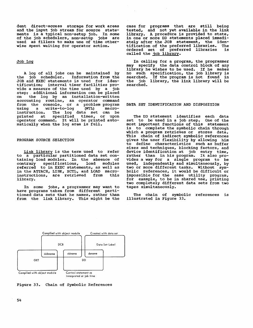
dent direct-access storage for work areas and the input job stream for source statements is a typical non-setup job. In some of the job schedulers, non-setup jobs are used as fillers to make use of time otherwise spent waiting for operator action.
Job Log
A log of all jobs can be maintained by the job scheduler. Information from the JOB and EXEC statements is used for identification; interval timer facilities provide a measure of the time used by a job step; additional information can be placed on the log by an installation-written accounting routine, an operator command from the console, or a problem program using a write-to-log (WTL) macroinstruction. The log data set can be printed at specified times, or upon operator command. It will be printed automatically when the log area is full.
PROGRAM SOURCE SELECTION
Link library is the term used to refer to a particular partitioned data set containing load modules. In the absence of contrary specifications, load modules referred to in EXEC statements, as well as in the ATTACH, LINK, XCTL, and LOAD macroinstructions, are retrieved from this library.
In some jobs, a programmer may want to have programs taken from different partitioned data sets that he names, rather than from the link library. This might be the
Compiled with object module Created with data set
DCB
dcbname
GET
Compiled with object module
Data Set Label
ddname dsname
DD
Control statement as interpreted at job time
Figure 33. Chain of Symbolic References
54
case for programs that are still being tested, and not yet available in the link library. A procedure is provided to state, in one or more DD statements placed immediately after the JOB statement, the identification of the preferred libraries. The ordered set of preferred libraries is called the job library.
In calling for a program, the programmer may specify the data control block of any library he wishes to be used. If he makes no such specification, the job library is searched. If the program is not found in the job library, the link library will be searched.
mATA SET IDENTIFICATION AND DISPOSITION
The DD statement identifies each data set to be used in a job step. One of the most important functions of this statement is to complete the symbolic chain through which a program retrieves or stores data. This chain of indirect symbolic references gives the user flexibility by allowing him to define characteristics such as buffer sizes and techniques, blocking factors, and device identification at job entry time, rather than in his program. It also provides a way for a single program to be used, independently and Simultaneously, by two or more different tasks. Without symbolic references, it would be difficult or impossible for the same utility program, for example, to be in shared use, printing two completely different data sets from two tapes simultaneously.
The chain of symbolic references is illustrated in Figure 33.

The first reference is the GET dcbname, where data input is requested. The second is in the DCB statement of the program, where the ddname is referenced. The third is the DO statement, \t1here the ddname is related to the data set name to be used during the current execution of the program. The paragraphs that follow outline in brief some of thE~ ways of identifying and controlling data sets by parameters in the DO statement.
SYSIN and the DO * Statement
Original input data (e.g., keypunched cards) may be presented to the system in an input job stream, together with the control statements. This minimi:~es operator setups of input/output devices. such data immediately follows a DO asterisk (DO *) statement. An example of this statement is:
//SYSIN DD * (data) (data)
An internal unique data set name is generated by the job scheduler for this data, but the data set is no·t cataloged. The generated name is used only for the duration of the job.
Depending on the configuration, input presented in this way is available to the user's program either directly from the card reader (or other input job stream devic~ or from a direct-access device onto which the job scheduler places the data prior to job execution.
In the preceding example, convention was followed in assigning SYSIN as the ddname. The actual ddname chosen is immaterial, so long as the name in the input job stream matches the name used in the program. Furthermore, the selection of a ddname -specifically, SYSIN -- in no way constrains the program to receive its input from the input job stream. The actual source of data is not specified until the SYSIN DD statement is entered in the input job stream.
That statement may specify a different data source. For example, if the programmer wants to use a previously transcribed and cataloged dat.a set named HAROLD.TESTPROG, the following statement could be used instead of the DD asterisk statement:
//SYSIN DD DSNAME=HAROLD.TESTPROG
No change in his program is necessary.
Concatenated Data Sets
When an application uses a sequence of two or more data sets as input, the control statements permit the programmer to concatenate (logically connect) the data sets for the duration of the job step. For example, five data sets, one produced on each day of a week, might be used as input to a single sort.
Each data set is described by a separate DD statement, but only the first DD statement is named; it is implied that each member of the group shares this common ddname. Each data set is used automatically, in the same sequence as the DD statements, whenever the ddname is used.
Generation Data Groups
The programmer can identify data sets belonging to generation data groups, in which the names are identical except for generation number. Data sets of this type of group are deSignated by either relative notation, or by the full name including generation number.
Dummy Data Sets
A general purpose program may require that one of its input requirements, or a regularly scheduled report, be ignored. Also, during early phases of a program debugging, it may be desirable to test only program flow, rather than full processing of data from data sets. These techniques are possible with sequential data organizations by use of the DUMMY parameter of a DD statement. Data sets so identified are not assigned to input/output units, the OPEN procedure is simplified, and any attempt within the program to store in or retrieve from the dummy data set results in an end-of-data condition on input and is treated as a -no operation- on output.
For example, in the first run of a tape file maintenance program, the master file may not yet exist. A dummy master file could be specified as input; the transaction file by itself becomes the first actual master file.
Job Management 55

Data Set Disposition
For each data set used, the programmer has a variety of options for the action to be taken by the system at the end of the ~ob step. He may specify that a data set 1S to be treated as system output and printed or punched, using the output writer feature of the job scheduler; or cataloged in the library; retained but not cataloged; deleted at the completion of the job step; or treated as a temporary data set. A temporary data set is handled as if it were cataloged during the remainder of the job's execution, but is automatically deleted at the end of the job. A temporary data set is, in effect, passed to succeeding steps. This type of data set is often used for temporary storage of a compiler's output that serves as the input to the linkage editor in a later job step.
The programmer may. also designate volumes that are to rema1n mounted throughout an entire job; he may also designate whether or not the system is allowed to use a direct-access volume for storage of other data sets. These latter features ensure that a volume intended for repeated use over a span of several job steps is not dismounted and remounted unnecessarily, and that volumes are not used for data sets that have not been specifically designated to reside there.
If no disposition instructions are given in the DD statement, a normal procedure is followed. Data sets created during a job step are deleted at the end of the step;
Selector Channel
1
Selector Channel
2
Figure 34.
56
Direct Access Control
Tape Control
Tape Control
Typical Input/Output Devices
data sets that were already in existence are retained.
INPUT/OUTPUT DEVICE ALLOCATION
Allocation of input/output devices is done by the job scheduler before job step initiation, according to a number of different considerations. One of these is the allocation requests included in each DD statement; others are the devices available and the system generation parameters. In general, it is not necessary to specify allocation of specific devices. The job scheduler will make reasonable assignments. There are applications, however, where the performance of a job depends very much on the device types and channels used for certain data sets. To handle this, the system accepts allocation requests and requirements in a variety of forms. Even
;so, the programmer gains flexibility and -improved overall performance if he states his requests in a general way, rather than being specific.
Individual input/output devices and arbitrary groups of input/output devices can be given permanent symbolic names for allocation purposes. The symbolic name :requested in the DD statement should be the least restrictive one appropriate to the situation. For example, the group of input/output devices in Figure 34 illustrates two IBM 2311 Disk Storage Drives and eight tape drives (four of the tapes are IBM 2400 Tape Drives, Model 1, and four are IBM 2400 Tape Drives, Model 2) •

Table 2. Names of Installation Devices r----------T--------·---T-------------T------------------~--------------------, I I 2311 Disk I 2311 Disk I Channell tapes I Channel 2 Tapes I I I I ~----------~---------+----------T----------i I Name I Storage D:ri ve I Storage Drive I Mod 1 I Mod 2 I Mod 1 I Mod 2 I I I I r-----r-----+_----T----+----T-----+----T-----i I I #1 1 #2 1 11 1 #2 1.1 1'2 1 11 1 12 1.1 1 #2 I ~-----------+----------.----+-------------+.----+-----+-----+---+_---+-----+----+-----i I SEQUEN 1 x 1 x 1 x 1 x 1 x 1 x I x 1 x I x I x 1 1 TAPE 1 I 1 x 1 x I x 1 x 1 x 1 x I x I x 1 1 DIRECT 1 x 1 xliii 1 1 1 1 1 ~------------+--------------+--------------+----+-----+-----+----+----+-----+----+-----i I CH 1 TAPEX I I I x I x I x I x I I I I I 1 CH2TAPEX I 1 I 1 I I 1 x I x I x I x I ~------------+----------,---+--------------+----+-----+-----+----+_---+-----+----+-----i I CH 1 MOD 2 I I I I I x I x I I I I 1 I CH2MOD2 1 1 I 1 1 I 1 I 1 x 1 x 1 1 MOD2TAPE 1 1 1 I 1 x I x 1 I 1 x I x I ~--------------+--------------+--------------+.----+-----+_----+----+----+-----+----+-----i 1 CH 1 TAPE 1 1 1 1 x 1 I 1 1 1 1 1 1 1 CH1TAPE3 1 1 1 1 I x I 1 I 1 1 I 1 CH2TAPE 1 1 1 1 1 I I I x I 1 I I L _____________ ~ ______________ ~ ______________ ~ ____ ~ _____ ~ _____ ~ ____ ~ ___ ~ _____ ~ ____ ~ _____ J
Table 3. Specifications That Achieve Input/OUtput Overlap r-----------------T----------------T----------------T----------------T------------------, I I I I I I 1 I Case 1 I Case 2 I Case 3 I Case 4 I ~------------------+----------------+----------------+----------------+------------------i IData Set 1 I CH1TAPE1 1 CH1MOD2 I CH1TAPEX I TAPE I ~-----------------+----------------+_---------------+----------------+------------------i 1 Data Set 2 1 CH2TAPE1 1 CH2MOD2 1 CH2TAPEX 1 CHAN=SEP I L _________________ ~ _______________ ~ ________________ ~ _______________ ~ __________________ J
Table 2 illustrates some names that might be used, and the units included under each name.
Specific allocation could be requested ~Y us~ng the name CH1TAPE3, but the system 1S g1ven more flexibility if a less restrictive name such as CH1TAPEX or MOD2TAPE is used instead. The use of restrictive requests may result in a job being held up if the specific un~t is not available.
To obtain input/output overlap between two data sets on tape, any of the combinations of statements in Table 3 could be used in order of increasing generality.
Case 4 is the least restrictive of the cases, and illustrates the way to request channel separation between two data sets, i.e., a different channel for each of the data sets. An extension of channel separation is the facility for channel affinity. If data 'sets A and B are to be assigned separate channels, then an affinity of data set C for A means that C and B should be given different channels. It does not necessarily mean that A and C share the same channel.
Volume affinity may be requested .between two data sets that are t:o be placed on the
same volume. This would be desirable with data sets on direct-access storage where their use is related, and the programmer wants to minimize disk pack mounting and demounting. This would also be desirable for two data sets that are created serially which the programmer wants on the same tape reel.
For large multivolume data sets on magnetic tape, where reels must be dismounted and mounted during a job step, spare or alternating drives can be requested to minimize operator setting up time, if extra tape drives are available. This is done by requesting that two tape drives be assigned to a single data set. In the case of output data sets, mounting a ·scratch" reel on one or more drives allows a drive to be assigned dynamically to anyone of several output data sets, whichever reaches the end of volume first. A ·pool· designation is used for such cases.
If an allocation request states the name of a nonexistent device, or a device declared by the operator to be unavailable, the associated job will be terminated. Requests for affinity or separation will only be followed if there are enough input/output devices in the system. If there are not enough, as when a tape drive
Job Management 57

has been removed for maintenance, the system ignores the affinity and separation requests, and runs the job using other units.
Deferred Mounting of Tapes
Normal operation of the job schedulers requires that the correct volumes be mounted on all input/output devices used by a job step before the step is initiated. This ensures that work will not be started, partially completed, and then forced to wait for operator action. Half-completed tasks, in a multitasking operation, tie up the system facilities and prevent other tasks from proceeding. In some cases, however, this precaution may be unnecessary or even undesirable. Some applications, by their design, allow sufficient mounting time during execution of an early phase to ensure that data sets needed on tape during a later phase, will be mounted in time. Other applications use a single unit, sequentially, for more than one data set. In such cases, the programmer may want to use the deferred mounting option, where a job step is allowed to proceed without first having all data sets in place.
DIRECT-ACCESS STORAGE SPACE ALLOCATION
The DD statement for data sets to be written out on direct-access storage contains requests for the needed space. Normally the amount of space to be initially allocated is specified, as well as the increments of space to be allocated automatically as needed. A request may be for space on a -private- volume, which means that no subsequent request for space will be allocated from that volume unless the volume is specifically designated. This allows direct-access volumes to be reserved for the exclusive use of, for instance, a programmer or an organizational department. Alternatively, the request may be nonspecific, which means that the request will be filled from available space on any volume other than previously designated private volumes.
Space may be requested in terms of tracks or cylinders; or it may be requested in terms of blocks (i.e., physical records) • In the latter case, the system will compute the number of tracks or cylinders required. The program, in this instance, is independent of the characteristics of the direct-access unit that is used. To make most efficient use of available space, the logically contiguous tracks
58
or cylinders will not always be physically contiguous. Physically contiguous space will be allocated, if requested.
A series of DD statements may be used to request a split cylinder. This feature allocates space that is to be shared among each of the data sets involved. Each data set represented by one of the DD statements is given a specified percentage of the tracks on each of the allocated cylinders. The split-cylinder technique allows concurrent use of two or more data sets on the same volume without excessive access arm movement.
CATALOGED PROCEDURES
Frequently used control statement sequences may be prepared once and then cataloged in the system library. These control statement sequences, called cataloged procedures, can be reused upon demand.
Typical sequences of job steps and output requirements that might be predefined are:
Compile - Linkage edit - Execute - Print Edit input data - Sort - Update master
file - Print exceptions.
Control statement sequences that are to be cataloged are presented in the input work stream in the usual way. A JOB statement parameter indicates that the sequence is to be cataloged rather than executed. The sequence may contain one or many job steps. Once cataloged, a procedure is called from the library by an EXEC statement that names the procedure to be executed, rather than naming a program. The entire cataloged procedure is then substituted in place of the EXEC statement that named it.
Temporary changes can be made to cataloged procedures, for the current job only, by statements in the input job stream whose names match those of cataloged procedure statements. Input job stream statements override cataloged statements, but do not change what is cataloged.
JOB SCHEDULER AND MASTER SCHEDULER FUNCTIONS
Job management contains four major fUnctional areas. Each area includes a number of selectable options. The four functional areas are:
• Job scheduler: reader/interpreter

• Job scheduler: ini tia'tor/terminator • Job scheduler: output writer • Master scheduler
JOB SCHEDULER
Reader/Interpreter
Each reader/interpreter of a job scheduler is responsible for reading one input job stream, scanning the input data to identify control statements, interpreting and analyzing the control statements, and preparing the necessary control tables that describe each. job to the system. For systems with an input work queue, the reader/interpreter ensures that the control information is placed in the queue in priority sequence, and that the data following a DD * statement is stored separatelyon a direct-access device as a temporary data set.
Multiple reader/interpreter tasks may be functioning at the same time, each one transcribing control statements and data to direct-access storage concurrently with other task operations. All use the same input work queue. Since the subprograms of the reader/interpreters are reenterable, the same copy may be used by all concurrently performing reader/interpreter tasks.
Some systems have the ability to do remote stacked job processing, in which job control information is sUbmitted from remote on-line terminals. A reader/interpreter task is attached to handle the job control statements forwarded through the queued telecommunications access method. The control information is placed in the input work queue and handled in the same manner as locally submitted jobs. Output data sets from remote jobs are handled by an output writer task as described later, except that the system also provides for routing the output data to specified terminals. This is described in detail in the publication IBM Operating System/360: Telecommunications.
Initiator/Terminator
The initiator of the job scheduler is responsible for selecting jobs to be executed and performing necessary preparatory work. The selection is made directly from an input job stream, or from an input work queue, depending on the configuration. For each step of a selected job, the initiator ensures that all necessary input/output
devices are allocated, that direct-access storage space is allocated as required, and that the operator has mounted any necessary tape and direct access volumes. It finally requests that the supervisor give control to the program named in the job step.
At job step completion, the terminator of the job scheduler is responsible for removing the work description from control program tables, freeing input/output devices, and disposing of data sets according to instructions in the DD statements.
As part of the input/output device allocation function, the initiator/terminator is responsible for issuing operator messages calling for volume mounting, and ensuring that the mounted volumes actually match allocation requests in the control statements. The following paragraphs present the three features that are optionally supplied to help minimize system time loss due to operator setup.
• projected Mount. The operator is given volume mounting messages a number of job steps in advance of that being initiated. Operator setup time can be overlapped with the execution of the previous job step.
• Automatic Volume Recognition. With this feature, the operator may premount labeled nine-track tape reels on any available unit; the job scheduler will record in a table the identification of each volume and the unit used. When a particular tape reel is needed for job step set-up, the table will be searched. If the needed reel is found to be already mounted, the usual procedUre of issuing a mounting message will be bypassed. This feature is particularly advantageous in production installations where work schedules usually are set in advance and follow a repeated pattern. In this situation, the operator usually knows in advance which tape reels are to be used and the sequence in which they will be required. Automatic volume recognition is also desirable with those configurations which perform jobs in the same sequence in which they appear in the input job stream.
• Non-Setup Padding. Jobs not requiring any operator setup action can be identified in the JOB statement. When any job step requiring setup is delayed because operator action is not complete, the initiator/terminator can scan the input work queue, find the highest priority non-setup job, and immediately initiate its first step. On completion of that step, the initiator/terminator checks to see if operator action is complete. If so, the job step requiring setup is ini-
Job Management 59

tiated; if not, the next step of the non-setup job is initiated and run and the procedure is repeated.
A more advanced version of the initiator/terminator is optional for larger systems where it is practical to have more than one job from the input work queue under way at one time. This capability is called multijob initiation. When the system is generated, the user specifies the maximum number of different jobs that the initiator is to have under way simultaneously.
Each selected job is run sequentially (one step at a time) just as with single job initiators. However, additional jobs are selected from the queue and initiated as long as:
• The number of jobs specified by the user is not exceeded.
• Enough input/output devices are available to satisfy allocation requests.
• Enough main storage is available for all current requirements and for the initiator program itself.
• Jobs are in the input work queue ready for execution.
• The initiator has not been detached by the operator.
Job Selection
Job High Priority
Job
I > Job Job 1 Job 2
Input Job Job
Stream Job
Job
Input Work
Queue
Low Priority
Job 1 Step A
Figure 35. Multijob Initiation
60
Job 2 Step A
Figure 35 illustrates the selection of three jobs from the input work queue and the initiation of one step from each as a task. The allocation method used by the multijob initiator ensures that each job selected will have input/output devices allocated to it before any jobs selected later are assigned their devices.
Multijob initiation may be used to advantage to initiate jobs in an application where a series of "batch-type" jobs are to run simultaneously with an independent job requiring input from remote terminals. Typically, such telecommunications jobs have frequent periods of inactiVity due either to periods of low traffic or to delays for direct-access seeks. During such delays, locally available jobs can be executed. (Because multijob initiation is a more generalized way to optimize device allocation, the non-setup padding facility may not be combined with it.)
OUtput Writers
During program execution, output data sets with a "system output" disposition may be stored on a direct-access storage device at high speed. Later, an output writer of
Job 3
Job 3 Step A

the job scheduler can transcribe the data to a system output unit, normally a printer or punch. Whenever this is done, control information regarding the output data sets is stored in an output work queue. An output data set can be retained indefinitely and still be prociessed by an output writer. Each system output device in operation is controlled by an output writer task; each device can be started or stopped independently by the operator.
Groups of output devices can be logically grouped together as a class to handle work of similar nature. For example, a single printer might be designated as a class to handle all high-priority, lowvolume printed output, and two printers might be designated fo:r all high-volume printing.
The DD statement allows output data sets to be directed to a class of devices, and allows the specification of a form number or card electro number code. This number is given to the operator before printing or punching starts so that 'the forms in the output unit can be prope:rly set up.
Output data destined for an output writer mayor may not be referred to by the ddname ·SYSOUT.- However, SYSOUT must be specified on the DD statement as the disposition of the data set. It is this specification that places i::t reference to the data on the output work queue. The queue is maintained in priori,ty sequence, allowing the output writers to select data sets on a priority basis.
In systems with input and output work queues on direct-access devices, the output writer is the final linllt in a chain of control routines designed to ensure fast turn-around time. Turn-around time, in this case, is considered to be the time from entry of the work statement in the computer until a usable output is obtained. Fast turn-around is achieved largely because of two factors: data at two intermediate stages of the work flow is accessible as soon as it is prepared, without any requirement for hatching; and at each such stage, priorities are used to place important work ahead of less important work that may have been previously prepared. The two intermediate stages are: when the job has just been entered in the input work queue , and when the job is completed with references to output data in the output work queue.
Output Work Queue
(1) (2) (3) A
Input Work Queue
A BCDEFG
Input Job Stream
ABC---Z BCD---Z H$J---Z
(4) ABC (5) (A) $BC
$DEFGH DEFGHJ
JKL---Z KLM---Z
Line (1) illustrates jobs A through Z in the input job stream (perhaps a card reader) before any jobs have been entered in the input work queue.
Line (2) shows job A in the input work queue. The jobs that follow are still being read in. As soon as job A is entered in the queue, execution begins. There is no need to wait for jobs B through Z to
\:nter the work queue.
; Line (3) shows the situation when A has completed execution with its output referred to on the output queue. By this time, jobs B through G have been entered in the input queue. Since A's output is ready to be printed or punched, the output writer begins. There is no wait for the output that will be produced by the jobs that follow. Shown also on this line is a high-priority job (represented by the dollar sign). It is still in the input stream (card reader) and has not yet"been recog
nized by the system.
Line (4) shows the situation when ($) has entered the input queue. Jobs A through C have been completed; job A's output is still being printed. Job ($) is the next job selected by the job scheduler because of its priority, even though it entered the input work queue later than jobs D through H.
Line (~ shows the situation at the completion of job ($). By now the output of job A has been completed. The output of job ($) will be the ~ext set of data to be printed by the output writer, because of its priority, even though jobs Band C entered the input work queue first.
MASTER SCHEDULER
All systems have a master scheduler whose functions are to handle messages from the system to the operator, replies from the operator, and commands frOm the operator to the system.
Messages to the operator are initiated by use of the write-to-operator ~TO) or write-to-operator-with-reply (WTOR) macroinstructions. The WTO macro-instruction is used to supply information to the operator (or programmer) ; WTOR is normally used to request information from the operator.
The operator can issue various commands:
• Job action commands cause a change in
Job Management 61

62
the status of a job. For example, cancelling or suspending a job, or modifying its priority.
• System action commands cause changes in the actions taken by the three job scheduler functions. These commands may inform the system of a new device to be used in the input job stream, or of a device that is no longer available for allocation.
• Information requests allow him to inquire about the status of the system or of certain jobs.
• Information entries allow him to provide the system with current date and time, to enter information in the system log, and to reply to system or program requests for information (as a consequence of the WTOR macro-instruction) •
Operator commands normally are entered into the system from a device such as a console typewriter, but can also be placed as separate statements in an input job stream.

-All work submitted for processing must be formalized as a task (or part of a task) before it will be performed. A program is treated by the Operating System as data until the time that it is named as an element of a task. This is true regardless of the particular control program features that are selected.
There are, however, significant differences in the features available. Although the requirement that all work be performed under task control has no exception, the manner of controlling 1tasks is subject to considerable variation. The most Significant choice among the options available is the choice between single-task and multitask control.
No more than one task can exist in the single-task environment. On the other hand, several tasks may coexist in the multi task environment and compete for available resources on a priority basis.
Since both environments have to do with task control, a program that is written for the single-task environment and follows normal systems conventions will work equally well in the latter environment.
SINGLE-TASK OPERATIONS
In a single-task environment, the job scheduler operates as a 1:ask which uses a task control block that entered the system when the system was initialized. Each job step is executed as part of this task.
The task so defined is the only task that will exist in the system and so can have all available resources. Its program can have a Simple, oVE~rlay, or dynamic serial structure - one 0]: more load modules may be required.
The control program must first fetch the load module named in the EXEC statement. To do so it:
1. Finds the program, using the program name.
2. Allocates main storage space according to the program size and loading attributes stated in the library directory entry for the load module. (The loading attribute is specified by the programmer as input to the linkage editor run that produces the load
SECTION 6: TASK MANAGEMENT
module. It is discussed further below.)
3. Loads the program into main storage, relocating it as part of the process. This function is performed by program fetch.
Three loading attributes may be named in a linkage editor run. For convenience, all three are discussed below, although the third option, scatter loading, is never available for single-task operations:
1. If block loading is specified, the entire load module is placed in a contiguous main storage area.
2. If overlay loading is specified, sufficient contiguous main storage is reserved to contain the longest path in the planned overlay program. However, only the root segment is initially fetched.
3. If scatter-loading is specified, the control program loads the entire load module, but not necessarily in contiguous main storage locations. This has no effect on program execution. The scatter-loading capability allows load modules to be split according to control section boundaries. Even with the scatter-loading attribute, a load module will be block-loaded in the following instances:
• The control program does not have scatter-loading capability.
• There is a single main storage area large enough to contain the entire load module.
In no case will a single control section be split.
Once the load module (or root segment, in the case of overlay) is available in main storage, control is passed to the entry point associated with the module name. Logical flow of control thereafter is as explained in "Program Design and Preparation." If the load module fetched is the first subprogram of a serial dynamic program, then the subsequent load modules required are fetched in the same way as the first, with one exception: if the needed module is reusable and a copy is aI-ready in main storage, that copy will be used for the new requirement.
Control program routines are handled in much the sam~ way as user routines.
Some of the control program routines are resident in main storage at all times. The
Section 6: Task Management 63

first-level interruption handlers are examples. Other control program functions are called into main storage upon demand; these are termed transient control program routines. An example is the routine associated with the OPEN macro-instruction. When a control program transient routine has completed its function, it remains in storage until the storage space is required for some other use.
If a transient routine is in storage, and is called, the control program will use it directly without going through the findallocate-fetch process, since such transient routines are reenterable.
When a task is completed (normally or abnor~lly), control is returned to the superv1sor. The supervisor, recognizing the end condition, reports back to the job scheduler that the job step is complete.
ACTUAL FLOW OF CONTROL
The single-task control program provides for normal interruption handling, and hence provides for overlapped operation between a task and other asynchronous operations supported by the hardware, such as input/output and interval timer operations. The programmer is not concerned with the actual flow of control as a result of interruption handling, other than as a way to better understand the environment in which his program will be executed.
This actual flow of control is illustrated in Figure 36. Control passes to the supervisor by any interruption allowed by the hardware design, and is returned by the load program status word (LPS~ instruction.
Interruptions may be caused by a supervisor call instruction in the user's program. Such instructions are requests for some form of supervisory service, such as starting an input/output operation, which usually requires the execution of one or more privileged instructions. No matter what source language is originally used, the only way of obtaining such services while the task is being performed is by use of supervisor calls.
All other interruptions take place unexpectedly as far as the user's program is concerned. Although program and machine interruptions may be caused by the execution of an instruction in the user's program, the programmer cannot normally predict when such an interruption will occur. Input/output and external interruptions are entirely asynchronous with the execution of
64
the user's programs. As a consequence, 'Control will pass back and forth between the user program and the control program at all interruptions. This actual flow of .control is something that is entirely tran'sparent to the user's program; that is, the
. jprogram is unaware of the actions taken.·
User's Program Area Supervisor Area
SIMPLE
SAVE
RETURN
Figure 36. Actual Flow of Control
MULTITASK OPERATION
All task management functions described for single-task operations apply equally well for multitask operations. Each job step is executed as a task. The manner in which this takes place, which has been touched on in its various aspects in preceding sections, is illustrated in Figure 37. Named load modules are either reused (if they are in storage and reusable) or new copies are fetched.
: Interruptions are transparent to the user programs. As a result, programs following system conventions that are written for a single-task environment work equally well in multiple-task environments. However, considerably more is required of task management when many tasks compete in requesting system facilities. The manner in which these requests are handled is described in the following paragraphs.
The goal of the control program is to effectively isolate each job step from the others, and at the same time allow tasks to share system facilities where it is advan-
·tageous to do so.
Whether or not individual programs use 'multitask facilities, such as certain macro-instructions which create new tasks or which synchronize multiple tasks, the
: installation can benefit in a number of . ways from having a multitaskcontrol program. One of these benefits is concurrent
'operation of input readers and output writ:ers which improves turn-around time for all 'jobs, and allows special handling of high

r--' --f I
L _ + ___ T~k ___ l
I I I Program I I SIMPLE I I (Load I I Module) I I I L ______ ..J
I //DDNAMEl DD DSNAME=A I I //DDNAME2 DD DSNAME= B I I //DDNAME3 DD DSNAME=C I
Data Sets
1.~~J L ____________ --~
r-----~~~--- ----, : //STEPl EXEC PGM=SIMPLE L:
-------12. =-~ J 3.[~J
Figure 37. Job Step-Task Relationship
priority jobs. Another is that multijob initiation by the job scheduler is made possible, which allows two or more jobs to be under way at the same time.
A more direct benefit of multitask operation is simplified program design. Individual programs (or subprograms of complex programs) need not be as carefully planned to balance processing time with input/output time to gain efficient operation. An individual program may be rather inefficient if run alone, but in a multitask operation its waiting time can be used effectively to process other tasks. This is particularly important in programs which spend a relatively high proportion of time in seeking records in direct-access storage; for example, inventory programs in which transaction or inquiry records are received by the computer directly from remote terminals. The inventory may be, for example, of parts a'vailable, savings deposits balances, or airline seats available. Since a rapid response (updating master files or replying to the remote terminal) is required, mas·ter files must be on direct-access devices. Each incoming message must be processed by a program which in turn depends on direct-access storage retrieval. In sllch applications, each message can be processed by a separate task, many messages can be processed concurrently, and the seeks can be effectively overlapped.
TASK CREATION -- ATTACH
Tasks are created as a result of three different actions. These are:
• The operator performing the initial program loading operation, or using commands that start components of the job scheduler.
• The EXEC job control statement defining a job step, which in turn becomes a task to be executed.
• The ATTACH macro-instruction within a user's program calling for creation of a subtask. (Like a subprogram, a subtask generally notifies the higherlevel task that created it of its completion.)
The mechanism used in all of these situations except initial program loading is the ATTACH macro-instruction. The only difference is whether the ATTACH is issued by the control program or by a user-written program. (There are one or two other special cases in which the control program may issue the ATTACH as an indirect result of a service request, but these cases are of less importance in program design. They are in the QTAM access method and the SEGLD macro-instruction.)
Figure 38 shows the most elementary situation that could exist after initial program loading, and before any input readers have been started by the operator. This assumes that the user has chosen to have all input readers started and stopped under operator command. The master scheduler task exists in the system at all times.
Figure 39 shows the situation after the operator has started one input reader, the initiator, and one output writer, and after the first job step has been initiated. F'our of the five tasks are performing job management functions. The dotted lines show subtask relationships.
Section 6: Task Management 65

Control Program Tasks
TCB
Master Scheduler
Processing Program Tasks
(None)
Figure 38. Situation Immediately Initial Program Loading
After
The control program, in controlling the sharing of facilities between tasks, does not differentiate between control program :tasks and processing program tasks as such. It exercises control on the basis of task priority and storage protection key, and
: allocates system resources among all tasks . according to the general rules described in the following paragraphs.
RESOURCE ALLOCATION
Figure 40 shows the situation that exists after three jobs have been initiated to run simultaneously. The task created by job 1 , step 1 (A) is shown with two subtasks that it has attached (B1 and B2). One of these subtasks has attached its own subtask (C).
Many system resources are demanded by competing tasks. Even in a single-task control program, some resource allocation is necessary. In a multitask control program, many system facilities are treated as resources subject to control and allocation.
In situations where there are conflicting demands, the control program resolves
TCB
Master Scheduler
Control Program Tasks
------- --TCB
Reader
Process i ng Program Tasks
Writer Initiator
Figure 39. Situation With Reader, Writer, Initiator, and One Job Step
Control Program Tasks
TCB
Job 1 Step 1
A
Job 1 Step 1
C
User Program Tasks
TCB
TCB
Job 2 Step 1
Job 1 Step 1
B2
Figure 40. Situation After Initiating Three Concurrent Jobs
66
TCB
Job 3 Step 1
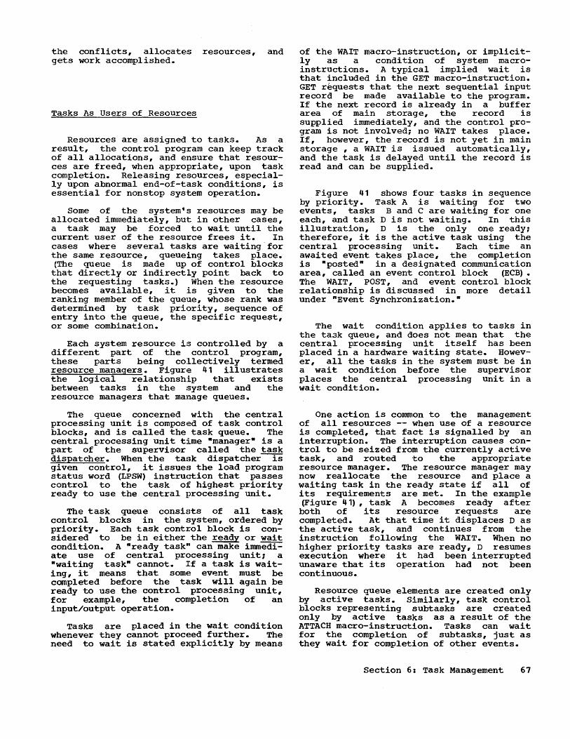
the conflicts, allocates resources, and gets work accomplished.
Tasks As Users of Resources
Resources are assigned to tasks. As a result, the control program can keep track of all allocations, and ensure that resources are freed, when appropriate, upon task completion. Releasing resources, especially upon abnormal end-of-task conditions, is essential for nonstop system operation.
Some of the system's resources may be allocated immediately, but in other cases, a task may be forced to wait until the current user of the resource frees it. In cases where several tasks are waiting 'for the same resource, queueing takes place. (The queue is made up of control blocks that directly or indirectly point back to the requesting tasks.) When the resource becomes available, it is given to the ranking member of the queue, whose rank was determined by task priority, sequence of entry into the queue, the specific reque$t, or some combination.
Each system resource is controlled by a different part of the control program, these parts being collectively termed resource managers. Figure 41 illustrates the logical relationship that exists between tasks in the system and the resource managers that manage queues.
The queue concerned with the central processing unit is composed of task control blocks, and is called the task queue. The central processing unit time "manager" is a part of the supervisor called the task dispatcher. When the taf3k dispatcher is given control, it issuef3 the load program status word (LPSW) instru(~ion that passes control to the task of highest priority ready to use the central processing unit.
The task queue consists of all task control blocks 1n the system, ordered by priority. Each task control block is considered to be in either the ready or wait condition. A "ready task" can make immediate use of central processing unit; a "waiting task" cannot. If a task is waiting, it means that some ev~nt must be completed before the task will again be ready to use the control processing unit, for example, the completion of an input/output operation.
Tasks are placed in the wait condition whenever they cannot proceed further. The need to wait is stated explicitly by means
of the WAIT macro-instruction, or implicitly as a condition of system macroinstructions. A typical implied wait is that included in the GET macro-instruction. GET requests that the next sequential input record be made available to the program. If the next record is already in a buffer area of main storage, the record is supplied immediately, and the control program is not involved; no WAIT takes place. If, however, the record is not yet in main storage , a WAIT is issued automatically, and the task is delayed until the record is read and can be supplied.
Figure 41 shows four tasks in sequence by priority. Task A is waiting for two events, tasks Band C are waiting for one each, and task D is not waiting. In this illustration, D is the only one ready; therefore, it is the active task using the central processing unit. Each time an awaited event takes place, the completion is "posted" in a designated communication area, called an event control block (ECB). The WAIT, POST, and event control block relationship is discussed in more detail under "Event Synchronization."
The wait condition applies to tasks in the task queue, and does not mean that the central processing unit itself has been placed in a hardware waiting state. However, all the tasks in the system must be in a wait condition before the supervisor places the central processing unit in a wait condition.
One action is common to the management of all resources -- when use of a resource is completed, that fact is signalled by an interruption. The interruption causes control to be seized from the currently active task, and routed to the appropriate resource manager. The resource manager may now reallocate the resource and place a waiting task in the ready state if all of its requirements are met. In the example (Figure 41), task A becomes ready after both of its resource requests are completed. At that time it displaces D as the active task, and continues from the instruction following the WAIT. When no higher priority tasks are ready, D resumes execution where it had been interrupted unaware that its operation had not been continuous.
Resource queue elements are created only by active tasks. Similarly, tas~ control blocks representing subtasks are created only by active tasks as a result of the ATTACH macro-instruction. Tasks can wait for the completion of subtasks, just as they wait for completion of other events.
Section 6: Task Management 67

Task Queues
Queued Tasks: D C B
PR = 3 PR = 4 PR = 10
W(I) W(I)
Queued Resource Requests: C
Queued Resource Requests: B
Figure 41. Resource Queues
Passing Resources to Subtasks
When subtasks are attached within a job step, they share some of the system resources assigned to the attaching task. The resources that are passed or shared, are:
• Storage protection keys. • Main storage areas. • Serially reusable programs, if not
already in use. • Reenterable programs. • Data sets, and the devices on which
they reside ..
Data sets to be used for a job step are initially presented to the job scheduler by DD statements. When the job scheduler creates a task for the job step, all such data sets are available to all load modules operating under the task. They may OPEN and CLOSE, store and retrieve, with no restriction other than heeding data set boundaries.
When a task attaches a subtask, it may pass the location of any data control block to the subtask. USing this, the subtask has equal access to the data set. When a job step is terminated, all data sets are automatically closed. However, when a subtask that has been given the location of an open data control block is closed, no such automatic closing of data sets takes place.
68
A Manager of PR = 12 CPU Time
W (2)
A Manager of Resource Alpha
A Manager of Resource Beta
EVENT SYNCHRONIZATION
WAIT and POST Macro-Instructions
Event synchronization is the delaying of task execution until some specified event occurs. The synchronization has two aspects:
• The requirement for synchronization is stated explicitly by the WAIT macroinstruction, or is implied by use of certain other macro-instructions.
• After the event has occurred, notice to the requesting task is given so it can proceed past the WAIT point.
The notification required is performed by the POST macro-instruction. When the event is known to the control program (for example, the completion of a read operation), the control program issues the POST. If the event is known only to the user's program, the user's program must issue it.
As an example, the function of both tasks A and B in Figure 42 is to compute some value, display it, and then proceed; the display of task A must precede that of B. Task A displays first, then issues the POST; task B waits for A, then displays its result.

(Calculate) DISPLAY
POST 9-----, (Calculate) WAIT
DISPLAY
Figure 42. Intertask Synchronization.
A task may make several different requests and then wait for any number of them. For example, a task may specify by READ, WRITE, and ATTACH macro-instructions that three asynchronous functions are to be performed. However, as soon as two of them have been completed, it is to be placed in the ready condition. When each of these requests is made initially to the control program, the location of a one-word event control block (ECB) is also stated. The event control. block provides the basic communication between the task issuing both the original requests and the subsequent wait, and the posting agency (in this case, the control program). When the WAIT macroinstruction is issued, the parameters supply the addresses of the event control blocks corresponding to the requested services. Also supplied is a wait count that specifies how many of the services (events) are required before the task is ready to continue.
When an event occurs, the following takes place:
• A ncomplete flag" in the appropriate event control block is set by the POST macro-instruction.
• A wait count test is made to see if the number of complete flags satisfies the wait condition, and hence if the task is ready.
• A "post coden specified in the POST macro-instruction is also placed in the event control block.. The post code gives additional information regarding the manner in which the completion occurred.
After the task has again been. given control, the programmer can determine what events did occur, and in what manner. He does this (with instructions following the WAIT macro-instruction) by testing each event control block.
Many requests for services may result in waits that are of no concern to the programmer -- for example, GETMAIN, GET, and PUT. In these cases, event control blocks and wait specifications al~e handled entirely by the supervisor or by accessing routines.
The programmer is responsible for clearing event control blocks before each use. It is imperative that the event to which an event control block pertains has occurred before it is reused.
Programmers intending to make use of the event synchronization facilities will find the following example helpful.
A READ macro-instruction within program SYNCH is followed by a wait for the completion of the input event. Figure 43 shows the situation immediately after the READ. The event control block required for the operation is located in a main storage area belonging to the task. Its address, nECBA n, was specified in the READ (1). The appropriate resource manager, the input/output supervisor, has queued the READ request and has placed the address ECBA in the queue element (2).
TCBA SYNCH
READ·· ·ECBA· ..
ECBA ..... 1 _____ --'
Input/Output Supervisor
. ECBA
Figure 43. Situation After READ
Figure 44 shows the situation at the time the WAIT macro-instruction is executed. In this example, the READ operation has not yet been concluded. The WAIT macro-instruction's parameters point to the event control block location, and state that only one event is needed to satisfy the WAIT. The supervisor, as a result of the WAIT macro-instruction, performs these actions:
• ~laces the task control block address, nTCBA n, in the event control block (1), and sets a single bit indicator (the "wait bit·) in the event control block to 1, meaning that a task is waiting for the event to take place •
• Sets a 1 in the wait count indicator in the task control block to show the number of events being awaited (2).
• Flags the task control block as being in the wait condition; therefore, its task is no longer eligible to use the central processing unit.
Section 6: Task Management 69
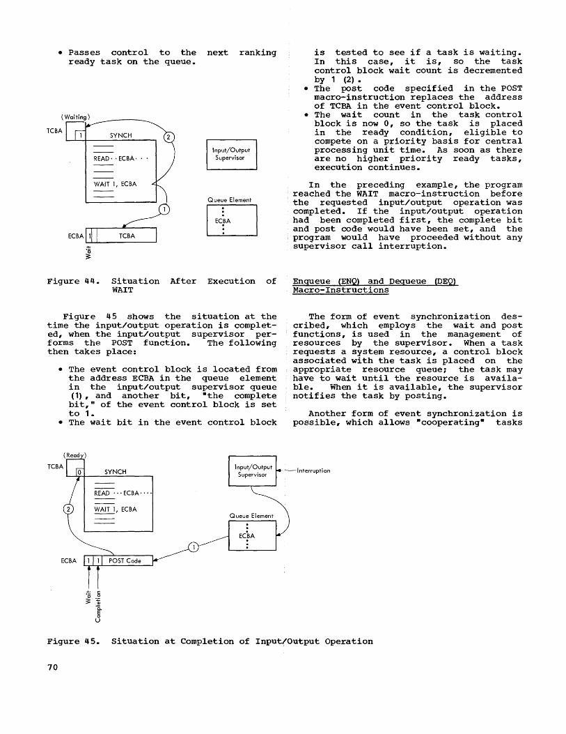
• Passes control to the ready task on the queue.
(Waiting)
TCBA SYNCH
READ, ,ECBA, • ,
WAIT I, ECBA
next ranking
Input/Output Supervisor
Queue Element
EJ Figure 44. Situation After Execution of
WAIT
Figure 45 shows the situation at the time the input/output operation is completed, when the input/output supervisor performs the POST function. The following then takes place:
• The event control block is located from the address ECBA in the queue element in the input/output supervisor queue (1), and another bit, "the complete bit," of the event control block is set to 1.
• The wait bit in the event control block
ECBA
SYNCH
READ'" ECBA ....
WAIT I, ECBA
'0 ,] 3: Q)
0.. 5 u
Queue Element
is tested to see if a task is waiting. In this case, it is, so the task control block wait count is decremented by 1 (2).
• The post code specified in the POST macro-instruction replaces the address of TCBA in the event control block •
• The wait count in the task control block is now 0, so the task is placed in the ready condition, eligible to compete on a priority basis for central processing unit time. As soon as there are no higher priority ready tasks, execution continues.
In the preceding example, the program reached the WAIT macro-instruction before the requested input/output operation was completed. If the input/output operation had been completed first, the complete bit and post code would have been set, and the program would have proceeded without any supervisor call interruption.
Enqueue (ENQ) and Dequeue (DEQ) Macro-Instructions
The form of event synchronization described, which employs the wait and post functions, is used in the management of resources by the supervisor. When a task requests a system resource, a control block associated with the task is placed on the appropriate resource queue; the task may have to wait until the resource is available. When it is available, the supervisor notifies the task by posting.
Another form of event synchronization is possible, which allows "cooperating" tasks
I nterrupti on
Figure 45. Situation at Completion of Input/Output Operation
70
to share certain resources defined by the user in much the same way. The resources that can be controlled in this way are called n serially reusablE!.·
The idea of serial reusability (brought out in the discussion of serially reusable programs), may be applied to a large variety of facilities. Thei.r common characteristic is that each may be used by all tasks that are associated with the same job step, but only one task may use them at one time. For example, the facility may be a table that has an entry with the value of 100. One task is to increment the value by 10, a second by 20. If the two tasks have concurrent access to the table, the first task may store 110, and t,he second task may store 120. The correct end value should, however, be 130.
If the programmer wants to control access to such a facility, he may create a queue of all tasks requiring access, and limit access to one task at a time. Specifically, in the case of serially reusable programs, he may want to queue tasks requiring such a program, instead of allowing the control program to fetch copies of it if the one in main storage is in use.
Queueing capabilities are available in the form of the two :macro-instructions enqueue (ENQ) and dequeue (DEQ). When ENQueue is used, a task will wait if the facility is in use; when DEQueue is used (after the task comple·tes its use of the facility), it will notify the first waiting task so that the facili·ty can again be used.
The enqueue macro-instruction (ENQ) provides the means by which concurrently operating tasks can be preven'ted from interfering with each other while using common data, or competing for a :Eacili ty that can not be shared. The natu:t'e of the facility is known only to the tasks that require it, and is of no concern 1to the operating system. All that the operating system needs is a queue control block that is provided by the programmer. When specified, ENQ causes a request to be placed in a queue associated with the queue control block. A check is then made to see if the nbusy indicatorn in the queue control block is on. If it is on, the serially reusable facility cannot yet be used, and the task issuing the ENQ is placed in the wait condition until its turn comes.
If the busy indicator is not on, the task issuing the enqueue is free to use the facility and will proceed to do so. Its queue element becomes first in the queue, the busy indicator is turned on (to block
later requests), and control is returned to the task.
When the task has finished with the facility, it must make it available to any other tasks that may be waiting for it. The dequeue (DEQ) macro-instruction is provided for this purpose. It causes the task's queue element to be removed, and the first of any pending queue elements to be activated; the busy indicator is set appropriately and the next pending request is satisfied by posting the appropriate waiting task.
TASK PRIORITIES
In a multi task operation, competing requests for service or resources must be resolved. For example: two or more job requests (i.e., sets of job control statements not yet acted upon) are available on the input work queue; two or more requests for use of a channel and control unit to gain access to an input/output device appear on the corresponding resource queue; two or more tasks in the ready state appear on the task queue, etc. In all of these situations the control program must decide what is to be done first. In some cases, choices are made by considering hardware optimization, for example, servicing requests for access to a disk in a fashion that minimizes disk seeking time. In most cases, however, the system relies upon a priority number provided by the user.
The user can best decide the priority criteria. He may combine in his selection such factors as the identification of the job requestor, response time requirements in teleprocessing applications, the amount of time already allocated to a task, or the length of the time that a job has been in the system without being processed.
The result of such considerations is a priority number ranging from 0 to 14 in order of increasing importance.
Initial priorities are specified on job statements and affect the sequence in which jobs are selected for execution. The operator is free to modify such priorities up to the time that the job is actually selected.
Further changes to priorities may be made dynamically by the change priority (CHAP) macro-instruction, which allows a
program to modify the priority of either the active task or of any of its subtasks. Controls are available to prevent unauthorized modification. The controls operate in the following way.
Section 6: Task Management 71
When the job scheduler initiates a job step, the current priority of the job (which may have been set by the operator) is used to establish a dispatching priority and a limit priority. The dispatching priority is used by the resource managers, where applicable, to resolve contention for a resource. The limit priority, on the other hand, serves only to control dynamic priority assignments.
Each task is free (by use of CHAP) to change its dispatching priority to any point in the range between zero and its limit. Furthermore, when a task attaches a subtask, it is free to set the subtask's dispatching and limit priorities at any point in the range between zero and the limit of the attacher. However, the subtask's dispatching priority ~ be higher than that of the attacher (although not higher than its own limit). For example, if task A, with limit and dispatching priorities both equal to 10, wants to attach subtask B with a higher relative dispatching priority than itself, it may proceed as follows:
1. Task A uses CHAP to lower its own dispatching priority to 7.
2. Task A attaches B with limit and dispatching priorities both equal to 8.
Lastly, a task may change the dispatching priority of any of its subtasks, so long as it does not exceed the higher level task's limit. Care should be exercised, for if the new dispatching priority is higher than the subtask's limit priority, the subtask's limit will be changed accordingly. For example, suppose A has a limit priority of 10, and attaches a subtask B with a limit priority equal to 8. A CHAP macro-instruction may be issued under task A which specifies that B's dispatching priority should be 9. Since 9 is less than A's limit, the request is valid. Since 9 is greater than B's limit, the limit priority of B will be changed to 9 as well as the dispatching priority.
Task priorities are used as criteria for temporary suspension of low priority tasks, called roll-out, in case sufficient main storage space is not available. This is described further under -Main Storage Allocation. •
Job priorities (the original priorities when tasks are initiated) are also used by the job scheduler's output writers to establish the sequence of output printing, punching, and similar functions specified in the job control statements.
72
It is expected that most installations will use only three levels of priority for batch-processing jobs in the normal input job stream. Normal work will automatically be assigned a median priority (as selected at system generation time). A higher number will be used for urgent jobs, and a lower one for -fillers· or deferred work.
TASK TERMINATION
Normally, programs signal completion of their execution by either RETURN or by XCTL, as described earlier. In the case of
RETURN, one of the general registers (called the return code regi'Ster) is used to transmit a return code back to the caller. If the program at the highest control level within the task executes a RETURN, the supervisor treats it as an automatic end-of-task signal. The return code at task termination may be inspected by the attaching task. In particular, it is used by the job scheduler to evaluate the condition parameters in job control statements.
In addition to the normal RETURN procedure above, any program operating on behalf of a task can execute an abnormal end (ABEND) macro-instruction to discontinue
task execution. Two cases may exist, depending on whether or not the terminating task has created a subtask which is still active. The situation with no subtask is illustrated in Figure 46. At (1) task A is attached by the job scheduler. At (2) an unusual condition is recognized, and ABEND is executed. The supervisor immediately takes any special termination action requested by the ABEND macro-instruction, such as causing a dump, and passing a completion code (a parameter of ABEND) to the attaching task to be recorded with key control areas in the supervisor. All resources of the task are released, except the task control block itself, and the event control block of the attaching task which is posted. At (3) the initiator/terminator proceeds with any termination procedure necessary, such as disposition of data sets and release of input/output resources. It then issues a DETACH macro-instruction, which is a request to the supervisor to eliminate the task control block from the system.
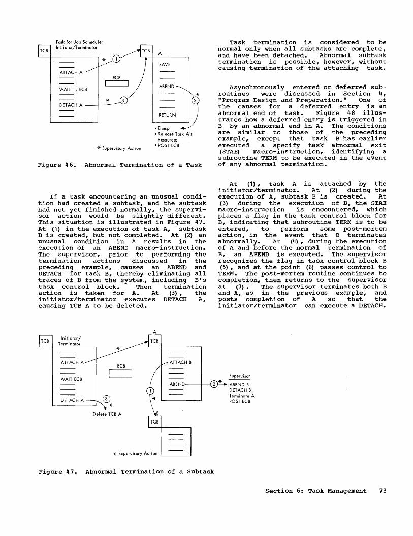
TCB
T ask for Job Scheduler Initiator/T erminator
ATTACH A
WAIT 1, ECB
ECB
* DETACH A --1---
* Supervisory Actnon
A
SAVE
ABEND
RETURN
• Dump • Release Task A's
Resources • POST ECB
Figure 46. Abnormal Termination of a Task
If a task encountering an unusual condition had created a subtask, and the subtask had not yet finished normally, the supervisor action would be slightly different. This situation is illustrated in Figure 47. At (1) in the execution of task A, subtask B is created, but not completed. At (2) an unusual condition in A results in the execution of an ABEND macro-instruction. The supervisor, prior to performing the termination actions discussed in the preceding example, causes an ABEND and DETACH for task B, thereby eliminating all traces of B from the system, including Bls task control block. Then termination action is taken for A. At (3), the initiator/terminator executes DETACH A, causing TCB A to be deleted.
TCB Initiator/ Terminator
ATTACH A
A
ECB ATTACH B
Task termination is considered to be normal only when all subtasks are complete, and have been detached. Abnormal subtask termination is possible, however, without. causing termination of the attaching task.
Asynchronously entered or deferred subroutines were discussed in Section 4, "program Design and Preparation." One of the causes for a deferred entry is an abnormal end of task. Figure 48 illustrates how a deferred entry is triggered in B by an abnormal end in A. The conditions are similar to those of the preceding example, except that task B has earlier executed a specify task abnormal exit (STAE) macro-instruction, identifying a subroutine TERM to be executed in the event of any abnormal termination.
At (1), task A is attached by the initiator/terminator. At (2) during the execution of A, subtask B is created. At (3) during the execution of B, the STAE
macro-instruction is encountered, which places a flag in the task control block for B, indicating that subroutine TERM is to be entered, to perform some post-mortem action, in the event that B terminates abnormally. At (4), during the execution of A and before the normal termination of B, an ABEND is executed. The supervisor recognizes the flag in task control block B (5), and at the point (6) passes control to
TERM. The post-mortem routine continues to completion, then returns to the supervisor at (7). The supervisor terminates both B and A, as in the previous example, and posts completion of A so that the initiator/terminator can execute a DETACH.
Supervisor WAIT ECB
ABEND--+---< 2 * ABEND B DETACH B Terminate A POST ECB DETACH A o
* Delete TCB A
* Supervisory Action L...-___ -I
Figure 47. Abnormal Termination of a Subtask
Section 6: Task Management 73
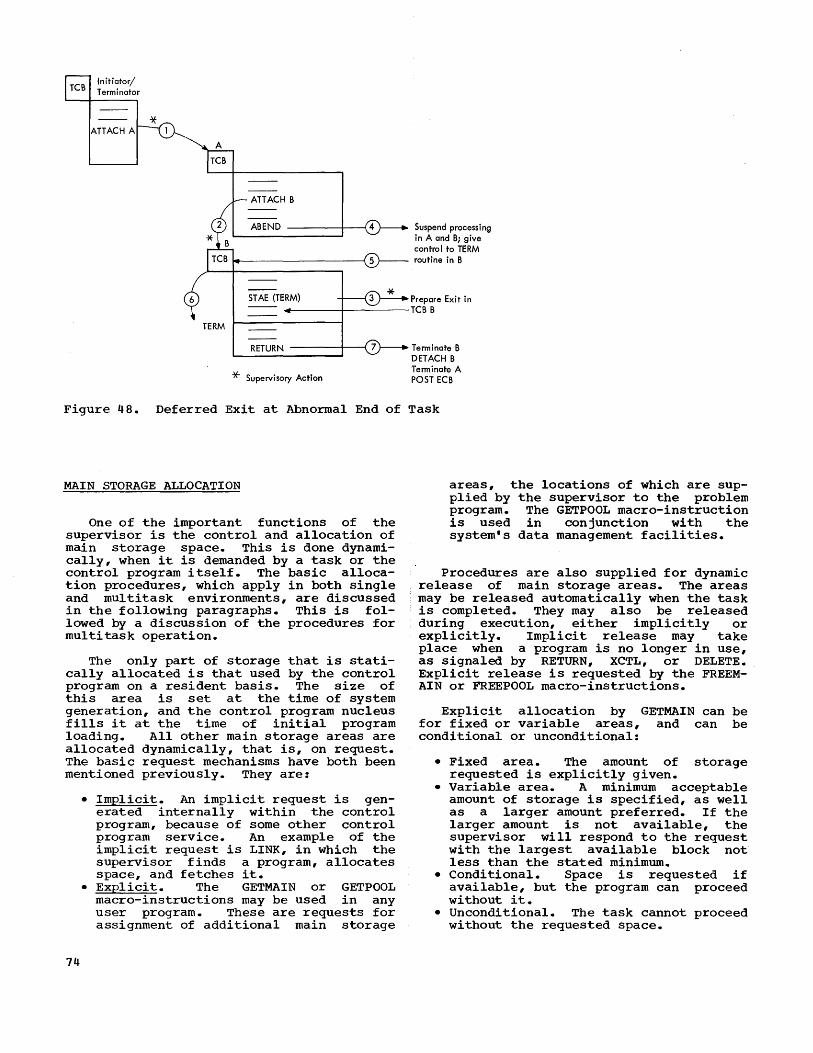
TCB Initiator/ Terminator
ATTACH B
ABEND ----t----t Suspend processing in A and B; give control to TERM routine in B
STAE (TERM) Prepare Exit in .------+---------TCBB
TERM
RETURN ----+--(
* Supervisory Action
Terminate B DETACH B Terminate A POST ECB
Figure 48. Deferred Exit at Abnormal End of Task
MAIN STORAGE ALLOCATION
One of the important functions of the supervisor is the control and allocation of ma1n storage space. This is done dynamically, when it is demanded by a task or the control program itself. The basic allocation procedures, which apply in both single and multitask environments, are discussed in the following paragraphs. This is followed by a discussion of the procedures for multi task operation.
The only part of storage that is statically allocated is that used by the control program on a resident basis. The size of this area is set at the time of system generation, and the control program nucleus fills it at the time of initial program loading. All other main storage areas are allocated dynamically, that is, on request. The basic request mechanisms have both been mentioned previously. They are:
74
• Implicit. An implicit request is generated internally within the control program, because of some other control program service. An example of the implicit request is LINK, in which the supervisor finds a program, allocates space, and fetches it.
• Explicit. The GETMAIN or GETPOOL macro-instructions may be used in any user program. These are requests for assignment of additional main storage
areas, the locations of which are supplied by the supervisor to the problem program. The GETPOOL macro-instruction is used in conjunction with the system's data management facilities.
Procedures are also supplied for dynamic release of main storage areas. The areas may be released automatically when the task is completed. They may also be released during execution, either implicitly or explicitly. Implicit release may take place when a program is no longer in use, as signaled by RETURN, XCTL, or DELETE. Explicit release is requested by the FREEMAIN or FREEPOOL macro-instructions.
Explicit allocation by GETMAIN can be for fixed or variable areas, and can be conditional or unconditional:
• Fixed area. The amount of storage requested is explicitly given.
• Variable area. A m1n1mum acceptable amount of storage is specified, as well as a larger amount preferred. If the larger amount is not available, the supervisor will respond to the request with the largest available block not less than the stated minimum.
• Conditional. Space is requested if available, but the program can proceed without it.
• Unconditional. The task cannot proceed without the requested space.

'MAIN STORAGE ALLOCATION IN A MULTITASK ENVIRONMENT
Since main storage is shared in a multitask environment, several factors should be considered when reserving space. To allow for effective use of space, the programmer should generally not, during assembly or compilation, reserve lar~Je blocks of main storage that are infrequently' used. Such blocks should be obtained and released dynamically. Work areas for reenterable programs must be obtained dynamically ~r passed by the higher level program as previously described) •
, On the other hand, since 'each dynamic
request takes some supervisor time to make and account for the allocation, requests for dynamic allocation and release of storage should generally not be repeatedly made for very small areas.
A number of additional storage considerations are:
• Storage protection between different tasks.
• Storage protection boundaries. • Need to pass or share storage areas
between related tasks. • , potential for noncontiguous main stor
age areas, and the possible use of scatter loading.
• Task priorities, and the potential need to clear storage areas so a high priority task can proceed.
These considerations form the basis for the storage allocation methods used by the multitask supervisor.
STORAGE PROTECTION AND PROTECTION BOUNDARIES
System/360 protects blocks of 2048 (2K) bytes of main storage. E:a.ch block can be given "a storage key in the range of 0 to 15. The operating system's supervisor areas are assigned key 01 the remaining keys are assigned to tasks created by the job scheduler. All of t.he tasks created from the same job step are given the same key.
Storage protection is a vital element in multi task operations. Undebugged programs may be tested at the same time production work is being run. Production programs can contain undetected errors that are not exposed until some peculiar combination of conditions is presented. The storage protection feature contains the effects of such conditions as much as possible, speci-
fically within the boundaries of a single job step. When the initiator/terminator creates a task from a job step, it gives the task a protection key· that it shares with its subtasks. The protection key is placed in the program status word when any task from the job step is in control of the central processing unit.
Storage areas allocated by the supervisor conform to the 2K- byte boundaries of the protection feature, on the basis of subpools. Each job step in the system is automatically assigned two logically different subpools, each consisting of one or more storage blocks. The first of these pools is used to store non-reusable and serially- reusable programs from any source, and reenterable programs from sources other than the link library. This pool is considered to be unnumbered. The second pool, numbered 00, is used for any task work areas obtained by the supervisor, and for filling unnumbered GETMAIN or GETPOOL requests. Optionally, requests may supply specific numbers, in which case numbered subpools are established. Established sub~ pools may be added to, deleted from, or entirely released.
The programmer, in requesting main storage areas, normally will not be concerned about the effect of the 2K-byte block size. Each request is filled by the supervisor from any available space within the set· of 2K-byte blocks assigned to the subpool, and additional blocks are assigned only if a large enough space does not exist. Requests for space may be made in the form of a list of independent requirements, so that noncontiguous main storage areas can be used to fill space requests. This method is used, for example, when fetching a load module with a scatter-load attribute. '
PASSING AND SHARING OF MAIN STORAGE AREAS
When the h'ighest level task of a job step (i.e., the task attached by the job scheduler) is terminated, all storage pools are released for reassignment. However, when a task attaches a subtask, and makes available to it storage areas (possibly containing data that is being passed as part of the linkag~, the release of those storage areas after the subtask has ,been terminated may not be desired. The higher level task may still want them.
To provide for this alternative, programs may call for the creation of subpools numbered 01 or greater. Each such subpool may be made available to a subtask at the time it is attached by passing or by
Section 6: Task Management 75

sharing. If a subpool created by a task is passed to a subtask, termination of the subtask will result in release of the subpool. If the subpool is shared, termination of the subtask will not result in the release of the subpool. In both cases, tasks that "receive" subpools (by passing or sharing) may add to them, delete from them, or even release them, in the same way as the originating task.
A subtask that "receives" a subpool may in turn pass it or share it with its subtasks. Whenever a subpool is passed, the higher level task surrenders all claims to it. Indeed, if the task then requests additional storage blocks for the subpool, a new subpool identified by the same subpool number would be formed. Whenever a subpool is shared, the higher level task retains a claim to the subpool. All tasks with claims to a subpool must be terminated before the subpool is automatically released.
A task may share a subpool with any number of subtasks that it attaches~ but it may not share and pass the same subpool, or pass the same sub pool more than once.
Subpool 00 refers to the same set of storage blocks for all tasks in a job step~ it therefore need not be passed or shared, nor is it released until the job step is complete.
TASK PRIORITIES AND ROLL-OUT
In multijob systems, the situation can arise where two or more job steps are being executed, and one of them makes an unconditional request for additional main storage space, either directly or indirectly, but no space is available for allocation. This situation is handled automatically by the
76
control program in the following way. First, the control program attempts to free main storage space occupied by a program that is in storage, but is neither in use nor reserved by a task. Failing that, a decision can be made to temporarily suspend the execution of one or more tasks, and remove information associated with them from main storage by writing it on an area of a direct-access device or on a magnetic tape. It is written in a format suitable for fast storage and retrieval. These operations of storage and retrieval of task information brought about by competing demands for main storage space are termed "roll-out" and "roll-in."
The decision to rollout a task or group of tasks is made primarily on the basis of task priority. A main storage demand by a high priority task will cause as many lower priority tasks to be rolled out as is necessary to satisfy the demand. If the lowest priority task in the system requires additional space to continue, it is placed in a wait state pending main storage availability.
When roll-out takes place, it is on a job step basis, that is, all tasks operating under a single job step are rolled out as a group. Roll-in takes place automatically, as soon as the original space is available again. The rolled-out group is brought back into storage exactly as it was at roll-out time, and continues execution from where it left off. All input/output operations under way at the time of the roll-out are completed before the roll-out takes place, so that no data is lost. During the time a task is rolled-out, its input/output units are not altered, so that repositioning information need not be saved. A rolled-out task is not completely removed from the system, since its task control block remains in a wait status, awaiting roll-in.

The material in this and other publications related tOo Operating System/360 describes the facilities offered by the system. System conventions relate to the use of those facilities. These conventions:
• Provide standardized methods, particularly for communication between routines within tasks and between tasks.
• Safeguard the user from using system facilities in a way that would require revision of his programs if the installation changes its computing or operating system configuration. They also help minimize effects of IBM changes or extensions of funct,ion to either the computing or the operating system.
Operating System/360 does not insist that the system conventions be followed, although in some cases it may call the attention of the user t,Q a violation of a convention. It is recognized that in some instances a deliberate violation of a convention is justifiable.
The co:qventions, descr'ibed in the following paragraphs, have to do with: names, subprogram linkages, programs that can be shared, communication between tasks, wait loops, operator messages, control section size, source language debugging, character sets, volume labels, and direct-access storage addresses.
The standard format for names is one to eight bytes, starting with an alphabetic character, without embedded blanks. No special characters are allowed within a name. Some variation to this general rule is allowed, according to the use that will be made of the name. For example, COBOL language allows for names written according to different rules than those stated.
Names may be applied to many different items within the operating system. Some are of concern only to programmers, but others are used by parts of the operating system and are of wider interest. Names need not be unique within the entire operating system. They must be unique, however, in the area in which they are used. It is important to understand these contexts to avoid duplications that could cause errors.
APPENDIX: SYSTEM CONVENTIONS
• System Components. These are arbitrary groupings used for convenience in ordering and distributing programs supplied by IBM. System component names will begin with some letter in the range of "A" through "I." Letters "J" through "Z" will not be used by IBM, and are therefore available to users.
• Object Modules. Each object module provided by IBM, if named, will have the same three initial letters as the system component of which it is a part.
• Load Modules. A load module (output from the linkage editor) will have a primary (program) name, and up to five additional aliases, each of which is associated with the name of an entry point for the load module. Each load module is stored as a member of a partitioned data set, on a directaccess storage unit. Load module names must be unique within each partitioned data set. Load module names need not be the same as the names of the object modules used to create them.
• Control Sections and External Symbols. Within a load module there will be one or more control sections that had been defined as part of an object module. IBM-written control sections and external references between control sections will use the same initial three letters as that used in the object module name.
• Data Sets. Every data set used by the operating system will be named at the time of use. The name will be declared explicitly in most cases, but in some instances may be generated internally. Reference from the program is to a data definition name in a DD control statement, which in turn specifies the actual data set name to be used.
Each data set name is made up of a simple name which may be preceded by one or more qualifiers, as was described in "Data Management." Simple names that are qualified need not be unique. Qualified names of data sets that are cataloged, or that are on the same volume must be unique.
All DD statement names used control program or IBM-supplied translator will start with the letters SYS.
by the language initial
Appendix: System Conventions 77

SUBPROGRAM LINKAGE
A standard procedure for subprogram linkage has been designed to give the greatest possible flexibility of use consistent with efficient program execution. For greatest flexibility of interconnection, all load modules in the system should use the standard linkage convention for intermodule linkage. Each load module should start with the SAVE macro and should terminate with the RETURN or XCTL macro, or their equivalents.
Subroutine linkage conventions are discussed in the publication, IBM Operating System/3 60: Control Program Services'.
PROGRAM SHARING
Sharable programs are either reenterable or serially reusable. Where possible, subprograms should be written and designated as one of these types. The advantage to be gained increases as the number of uses of the program increases.
INTERTASK COMMUNICATION
Definite rules are stated for the ATTACH macro-instruction, telling what parameters can be passed, and how. Techniques exist, however, which a programmer could use to bypass the supervisor's control and establish direct task-to-task intercommunication. It is strongly recommended that only the standard methods be used, because a nonstandard approach can cause system side effects that may be hard to find and to correct, particularly if there is any change in the supervisor due to new equipment, addition of selectable modules, or program updating.
USE OF WAIT
The programmer should use the WAIT macro-instruction in cases where event synchronization is needed, rather than programming a wait loop as has been common practice. Wait loops waste central processing unit time, and prevent the supervisor from allocating resources efficiently.
18
OPERATOR MESSAGES
A standard format and rules are provided for messages to and from the console operator. All IBM-supplied system components that produce operator messages will tag each message with a code that will identify the component. It is recommended that user programs follow a similar identification procedure.
CONTROL SECTION SIZE
Where practical to do so, the user should divide programs into control sections that are 4096 bytes, or slightly less. The reasons are:
• Addresses will be within the range covered by the displacement part of instructions using a single loading of a single base register.
• The control program can scatter load when appropriate.
• The supervisor can allocate main storage space efficiently. Programs that are at or under some multiple of 2048 bytes are most efficient, and those just over are least efficient.
When considering control section size, the user may consider the effect of program maintenance and modification, which can cause programs to change in size.
CHARAC~ER SET CONSIDERATIONS
System/360 permits ,relatively free association between the internal bit structure of a byte and the graphic symbol represented. The TRANSLATE instruction simplifies any translations that may be needed. Even so, there are considerations that may affect program design. Some of these are:
• The number of characters in the set of each printer in the system, which is generally device dependent.
• The use of dual graphics for a single bit configuration. System/360 coding separates the graphics of the former -A" and "H- character sets used with the 1403 and other IBM printers. It is recommended that dual usage in installations be eliminated.
• The trend toward standardization of codes under the auspices of the American Standards Association and the International Standards Organization. Widespread use of a standard code structure might be reason for an installation to change internal codes.

It is strongly recommended that user programs be written so that they do not depend on specific relations between bit configurations and graphic symbols in cases where there is a possibility of character code change. Dependencies will be needed in some cases, in spite of oareful program design. such cases shoul.d be related to a table, if possible, in a way that would allow table replacement t.o handle any code change. In any event, it. is recommended that any character code-dependent sections of coding be clearly identified in all program documentation to help identify places where reprogramming might be needed.
SOURCE LANGUAGE DEBUGGING AND MAINTENANCE
Good programming practice requires that source language programs be maintained in an up-to-date condition at all times. Operating System/360 is designed to assist the user to keep source programs current and avoid the temptation to "patch" at the object program level. The general approach to program debugging is in.sertion of debugging statements using the same language and compiler facilities as the program being tested. Changes for test purposes, and for correction of errors, are made by recompiling only the object module in which the change is needed. The new or revised object module is then recombined with other modules using the linkage editor, to produce and store a load module for test.
VOLUME LABELS
The operating system provides a standard label procedure for all magnetic tape reels, disk packs, and data cells. With tapes, however, there may be compatibility considerations, and users may choose to incorporate their own nonstandard tapelabel handling procedures, or not to check tape labels. Details on system standards in this area are described in IBM Operatinq System/360: Data Manaqement.
.TRACK ADDRESS INDEPENDENCE
Space on direct-access storage units is allocated dynamically on a track or cylinder basis. To make the best use of available space, access methods have provisions to allocate physically separated tracks; and, for purposes of data access, to convert relative track addresses (that relate to the boundary of the data set) to actual track addresses. Therefore, for purposes of space allocation, as well as programming ease, programs should generally be written to use relative track addresses and remain independent of the actual addresses.
Appendix: System Conventions 79

GLOSSARY
access method: Any of the data management techniques available to the user for transferring data between main storage and an input/output device.
address constant: A value, or an expression representing a value, used in the calculation of storage addresses.
alias: An alternate name that may be used to refer to a member of a partitioned data set1 an alternate entry point at which execution of a program can begin.
allocate: To grant a resource to, or reserve it for, a job or task.
asynchronous: Without regular time relationship1 hence, as applied to program execution, unexpected or unpredictable with respect to instruction sequence.
attach (task): To create a task control block and present it to the supervisor.
attribute: A characteristic1 e.g., attributes of data include record length, record format, data set name, associated device type and volume identification, use, creation date, etc.
auxiliary storage: Data storage other than main storage.
basic access method: Any access method in which each input/output statement causes a corresponding machine input/output operation to occur. (The primary macroinstructions used are READ and WRITE.)
batch processing: processing. )
block (records):
(See stacked job
1. To group records for the purpose of conserving storage space or increasing the efficiency of access or processing. 2. A physical record so constituted, or a portion of a telecommunications message defined to be a unit of data transmission.
block loading: The form of fetch brings the control sections of a module into contiguous positions of storage.
that load main
buffer (program input/output): A portion of main storage into which data is read, or from which it is written.
catalog: 1. The collection of all data set indexes
80
, maintained by data management. 2. To include the volume identification of a data set in the catalog.
cataloged data set: A data set that is represented in an index or hierarchy of indexes which provide the means for locating it.
cataloged procedure: A set of job control statements that has been placed in a cataloged data set and can be retrieved by naming it in an execute (EXEC) statement.
checkpoint: 1. A point at which information about the status of a job step can be recorded so that the job step can be restarted. 2. To record such information.
concatenated data set: A collection of logically connected data sets.
control block: A storage area through Which a particular type of information required for control of the operating system is communicated among its parts.
control dictionary: The external symbol dictionary and relocation dictionary, collectively, of an object or load module.
control program: A collective or general term for all routines in the operating system that contribute to the management of resources, implement the data organization or communications conventions of the operating system, or contain privileged operations.
control section: The smallest separately relocatable unit of a program1 that portion of text specified by the programmer to be an entity, all elements of which are to be loaded into contiguous main storage locations.
control volume: A volume that contains one or more indexes of the catalog.
data control block: A control block through which the information required by access routines to store and retrieve data is communicated to them.
data definition name (ddname): A name appearing in the data control block of a program which corresponds to the name field of a data definition statement.
data definition (DO) statement: A job

control statement that describes a data set associated with a particular job step.
data manaqement: A general term that collectively describes those functions of the control program that pro-vide access to data sets, enforce data storage conventions, and regulate the use of input/output devices.
data organization: A term that refers to anyone of the data management conventions for the arrangement of a data set.
data set: The major uni"t of data storage and retrieval in the operating system, consisting of a collection of data in one of several prescribed arrangements and described by control information that the system has access to.
data set control block (DSCB) label for a data set in storage.
A data set direct-access
data set label (DSL): A collection of information that describes the attributes of a data set, and that is normally stored with the data set; a general term for data set control blocks and tape data set labels.
deferred entry: An entry into a subroutine that occurs as a result of a deferred exit from the program that passed control to it.
deferred exit: The passing of control to a subroutine at a time determined by an asynchronous event rather than at a predictable time.
device independence: The ability to request input/output operations without regard to the characteristics of the input/output devices.
direct access: Retrieval or storage of data by a reference to its location on a volume, rather than rela1:.ive to the previously retrieved or stored data.
dispatching priority: A number assigned to tasks, and used to determine precedence for use of the central processing unit in a multi task situation.
dump (main storage) : 1. To copy the contents of all or part of main storage onto an output device, so that it can be examined. 2. The data resulting from 1. 3. A routine that will accomplish 1.
entry point: which control program.
Any location in a program to can be passed by another
event: An occurrence 01: significance to a
task; typically, the completion of an asynchronous operation, such as input/output.
event control block (ECB): A control block used to represent the status of an e~ent.
exchange buffering: A technique using data chaining for eliminating the need to move data ln main storage, in which control of buffer segments and user program work areas is passed between data management and the user program according to the requirements for work areas, input buffers, and output buffers, on the basis of their availability.
exclusive segments: Segments in the same region of an overlay program, neither of which is in the path of the other. They cannot be in main storage simultaneously.
execute (EXEC) statement: A job control statement that designates a job step by identifying the load module to be fetched and executed.
extent: The physical locations on input/output devices occupied by or reserved for a particular data set.
external reference: A reference to a symbol defined in another module.
external symbol: A control section name, entry point name, or external reference; a symbol contained in the external symbol dictionary.
external symbol dictionary (ESD): Control information associated with an object or load module which identifies the external symbols in the module.
fetch (program): 1. To obtain requested load modules and load them into main storage, relocating them as necessary. 2. A control routine that accomplishes 1.
F format: which the length.
A data logical
set record records are
format in the same
generation data group: A collection of successive, historically related data sets.
inclusive segments: Overlay segments in the same region that can be in main storage simultaneously.
index (data management) 1. A table in the catalog structure used to locate data sets. 2. A table used to locate the records of an indexed sequential data set.
initial program loading (IPU: As applied to the operating system, the initialization
Glossary 81

procedure which loads the nucleus and begins normal operations.
initiator/terminator: The job scheduler function that selects jobs and job steps to be executed, allocates input/output devices for them, places them under task control, and at completion of the job, supplies control information for writing job output on a system output unit.
input job stream: A sequence of job control statements entering the system, which may also include input data.
input work queue: A queue of summary information of job control statements maintained by the job scheduler, from which it selects the jobs and job steps to be processed.
installation: A general term for a particular computing system, in the context of the overall function it serves. and the individuals who manage· it, operate it, apply it to problems, service·it, and use the results it produces.
job: An externally specified unit of work for the computing system from the standpoint of installation accounting and operating system control. A job consists of one or more job steps.
job control statement: Anyone of the control statements in the input job stream that identifies a job or defines its requirements.
job library: A concatenation of useridentified partitioned data sets used as the primary source of load modules for a given job.
job management: A general term that collectively describes the functions of the job scheduler and master scheduler.
iob scheduler: The control program fUnction that controls input job streams and system output, obtains input/output resources for jobs and job steps, attaches tasks corresponding to job steps, and otherwise regulates the use of the computing system by jobs. (See reader/interpreter, initiator/terminator, output writer.)
job (JOB) statement: The control statement in the input job stream that identifies the beginning of a series of job control statements for single job.
job step: A unit of work for the computing system from the standpoint of the user, presented to the control program by job control statements as a request for execution of an explicitly identified program and a description of resources required by
82
it. A job step consists of the external specifications for work that is to be done as a task or set of tasks. Hence,- also used to denote the set of all tasks which have their origin in a job step specification.
language translator: A general term for any assembler, compiler, or other routine :that accepts statements in one language and produces equivalent statements in another language.
·library: 1. In general, a collection of objects (e.g. , data sets, volumes, card decks)
,associated with a particular use, and the :location of which is identified in a direc:tory of some type. In this context, see job library, link library, system library. 2. Any partitioned data set.
limit priority: A priority specification associated with every task in a multitask operation, representing the highest dispatching priority that the task may assign to itself or to any of its subtasks.
link library: A generally accessible par·titioned data set which, unless otherwise :specified, is used in fetching load modules referred to in execute (EXEC) statements :and in ATTACH, LINK, LOAD, and transfer control (XCTL) macro-instructions.
linkage: The means by which communication is effected between two routines or modules.
linkage editor: A program that produces a load module by transforming object modules into a format that is acceptable to fetch, combining separately produced object modules and previously processed load modules into a single load module, resolv'ing symbolic cross references among them, ·replacing, deleting, and adding control sections automatically on request, and providing overlay facilities for modules requesting them.
:load: To fetch, :module into main executing it.
i.e., storage
to read a load preparatory to
:load module: The output of the linkage editor; a program in a format suitable for ;loading into main storage for execution.
:locate mode: A transmittal mode in which ldata is pOinted to rather than moved.
'logical record: A record from the stand-pOint of its content, function, and use rather than its physical attributes; i.e., one that is defined in terms of the information it contains.

macro-instruction: A general term used to collectively describe a macro-instruction statement, the corresponding macroinstruction definition, the resulting assembler language st,atements, and the machine language instructions and other data produced from the assembler language statements; loosely, anyone of these representations of a machine language instruction sequence.
main storage: All addressable storage from which instructions can be executed or from whioh data can be loaded directly into registers.
master scheduler: The control program function that responds to operator commands, initiates actions requested thereby, and ret urns r~:!!quested or required information; thus, the overriding medium for controlling the use of the computing system.
module (programming): The input to, or output from, a singlE~ execution of an assembler, compiler, or linkage editor; a source, object, or load module; hence, a program unit that is discreet and identifiable with respect to compiling, combining with other units, and loading.
move mode: A transmittal mode in which data is moved between the buffer and the user's work area.
multijob operation: A 'term that describes concurrent execution of job steps from two or more jobs.
multiprogramming: A general term that expresses use of the computing system to fulfill two or more different requirements concurrently.
multitask operation: Multiprogramming; called multitask operation to express parallel processing not only of many programs, but also of a single reenterable program used by many tasks.
~ A set of one or more characters that identifies a statement, data set, module, etc., and that is usually associated with the location of that which it identifies.
nucleus: That portion of the control program that must always be present in main storage. Also, the main storage area used by the nucleus and other transient control program routines.
object module: The 01lltput of a single execution of an assembler or compiler, which constitutes input to linkage editor. An object module consists of one or more control sections in relocatable, though not
executable, form and an associated control dictionary.
operator command: A statement to the control program, issued via a console device, which causes the control program to provide requested information, alter normal operations, initiate new operations, or terminate existing operations.
output work queue: A queue of control information describing system output data sets, which specifies to an output writer the location and dispoSition of system output.
output writer: A job scheduler function that transcribes specified output data sets onto a system output unit, independently of the program that produced such data sets.
overlay: To place a load module or a segment of a load module into main storage locations occupied by another load module or segment.
overlay (load) module: A load module that has been divided into overlay segments, and has been provided by linkage editor with information that enables overlay supervisor to implement the desired loading of segments when requested.
overlay segment: (See segment.)
overlay supervisor: A control routine that initiates and controls fetching of overlay segments on the basis of information recorded in the overlay module by linkage editor.
parallel processing: Concurrent execution of one or more programs.
path: A series of segments which, as represented in an overlay tree, form the shortest distance in a region between a given segment and the root segment.
.... p~h~y...;s;;.;i=-c=-a;;;;.l~~r..;:e:;..;;c;..;o:;..;;r=-d;::;..;;..: A record from the st'andpoint of the manner or form in which it is stored, retrieved, and moved; i.e., one that is defined in terms of physical qualities.
polling: A technique by which each of the terminals sharing a communications line is periodically interrogated to determine if it reqUires servicing.
To note the occurrence of an event.
priority scheduling system: A form of job scheduler which uses input and output work queues to improve system performance.
private library parti tioned (lata
(of a job step): Any set which is neither the
Glossary 83

link library library.
nor any part of the job
problem program: Any of the class of routines that perform processing of the type for which a computing system is intended, and including routines that solve problems, monitor and control industrial processes, sort and merge records, perform computations, process transactions against stored records, etc.
processing program: A general term for any program that is not a control program.
protection key: An indicator associated with a task which appears in the program status word whenever the task is in control, and which must match the storage keys of all storage blocks which it is to use.
qualified name: A data set name that is composed of multiple names separated by periods (e.g., TREE.FRUIT.APPLE) •
qualifier: All component names in a qualified name other than the rightmost (which is called the simple name) •
queue control block (QCB): A control block that is used to regulate the sequential use of ,a programmer-defined facility among requesting tasks.
queued access method: Any access method that automatically synchronizes the transfer of data between the program using the access method and input/output devices, thereby eliminating delays for input/output operations. (The primary macroinstructions used are GET and PUT.)
reader/interpreter: A job scheduler function that services an input job stream.
ready condition: The condition of a task that it is in contention for the central processing unit, all other requirements for its activation having been satisfied.
real time (interval timer): Actual time.
record: A general term for any unit of data that is distinct from all others when considered in a particular context.
reenterable: The attribute of a load module that allows the same copy of the load module to be used concurrently by two or more tasks.
region: A contiguous area of main storage within which segments can be loaded independently of paths in other regions. Only one path within a region can be in main storage at one time.
84
relocation: The modification of constants required to compensate change of origin of a module or section.
address for a
control
~elocation dictionary: That part of an Object or load module which identifies all relocatable address constants in the ~odule.
resource: Any facility of the computing system or operating system required by a job or task and including main storage, ~nput/output devices, the central process~ng unit, data sets, and control and processing programs.
resource manager: A general term for any control program function responsible for the allocation of a resource.
restart: To reestablish the job using the information checkpoint.
status of a recorded at a
return code: A value that is by system convention placed in a designated register :(the "return code register") at tl1e completion of a program. The value of the code, which is established by user-convention, ~ay be used to influence the execution of succeeding programs or, in the case of an abnormal end of task, it may simply be printed for programmer analySis.
return code register: A register identified by system convention in which a userspecified condition code is placed, at the pompletion of a program.
reusable: The attribute of a routine that the same copy of the routine can be used by two or more tasks. (See reenterable, serially reusable.)
roll in: To reinstate a task or a set of tasks that had been rolled out.
rollout: To record on an auxiliary stor:age device the contents of main storage tocations associated with a task so as to :free main storage for allocation to a task ,of higher priority, and to do so at the !discretion of the control program rather than the task that is rolled out.
:root segment: That segment of an overlay program that remains in main storage at all 'times during the execution of the overlay program; the first segment in an overlay 'program.
scatter loading: The form of fetch that may place the control sections of a load module into non-contiguous positions of main storage.
scheduler: scheduler.)
(See master scheduler and job
secondary storage: Auxiliary storage.
seek: To position the access mechanism of a direct-access device at a specified location.
segment: 1. The smallest functional unit (one or more control sections) that can be loaded as one logical entity during execution of an overlay program. 2. As applied to telecommunications, a portion of a message that can be contained in a buffer of specified size.
sequential scheduling system: A form of the job scheduler which recognizes one job step at a time in the sequence in which each job appears in the input job stream.
serially reusable: The attribute of a routine that when in main storage the same copy of the routine can be used by another task after the current use has been concluded.
service program: Any of the class of standard routines that assist in the use of a computing system and in the successful execution of problem programs, without contributing directly to control of the system or production of results, and including utilities, simulators, 1:.est and debugging routines, etc.
short block: A block of which contains fewer logical are standard for a block.
F format data records than
simple buffering: A technique for controlling buffers in such a way that the buffers are assigned to a single data control block and remain so assigned until the data control block is closed.
simple name: The righ1:most component of a qualified name (e.g., APPLE is the simple name in TREE.FRUIT.APPL~ •
source module: A series of statements in the symbolic language of an assembler or compiler, which constitutes the entire input to a single execution of the assembler or compiler.
stacked job processing: A technique that permits multiple job definitions to be grouped (stacke~ for presentation to the system, which automatically recognizes the jobs, one after the other. More advanced systems allow job definitions to be added to the group (stack) at any time and from any source, and also hOllor priorities.
storage block: A contiguous area of main storage consisting of 2048 bytes to which a storage key can be assigned.
storage key: An indicator associated with a storage block or blocks, which requires that tasks have a matching protection key to use the blocks.
substitute mode: A transmittal mode used with exchange buffering in which segments are pointed to and exchanged with user work areas.
subtask: A task that is created by another task by means of the ATTACH macroinstruction.
supervisor: As applied to Operating System/360, a routine or routines executed in response to a requirement for altering or interrupting the flow of operations through the central processing unit, or for performance of input/output operations, and, therefore, the medium through which the use of resources is coordinated and the flow of operations through the central processing unit is maintained; hence, a control routine that is executed in supervisor state.
synchronous: Occurring concurrently, and with a regular or predictable time relationship.
SYSIN: A name conventionally used as the data definition name of a data set in the input job stream.
SYSOUT: An indicator used in data definition statements to signify that a data set is to be written on a system output unit.
system input unit: A device specified as a source of an input job stream.
system library: The collection of all cataloged data sets at an installation.
system macro-instruction: A pre-defined macro-instruction that provides access to operating system facilities.
system output unit: An output device shared by all jobs, onto which specified output data is transcribed.
system residence volume: The volume on which the nucleus of the operating system and the highest level index of the catalog are located.
~ A unit of work for the central processing unit from the standpoint of the control program; therefore, the basic multiprogramming unit under the control program.
Glossary 85

task control block (TCB): The consolidation of control information related to a task.
task dispatcher: The control program function that selects from the task queue the task that is to have control of the central processing unit, and gives control to the task.
task manaqement: A general term that collectively describes those functions of the control program that regulate the use by tasks of the central processing unit and other resources (except for input/output devices) •
task queue: A queue of all the task control blocks present in the system at any one time.
telecommunications: A general term expressing data transmission between a computing system and remotely located devices via a unit that performs the necessary format conversion and controls the rate of transmission.
teleprocessinq: A term associated with IBM telecommunications equipment and systems.
test translator: A facility that allows various debugging procedures to be specified in assembler language programs.
text: The control sections of an object or load module, collectively.
throughput: A measure of system
86
efficiency~ the rate at which work can be handled by a computing system.
transmittal mode: The contents of an input lable to the program, w~ich a program makes output.
method by which the buffer are made avai
and the method by records available for
turn-around time: The elapsed time between submission of a job to a computing center and the return of results.
U format: A ~locks are of u;nknown length.
data set format unspecified or
in which otherwise
user: Anyone who requires the services of a computing system.
V: format: A data set format in which logical records are of varying length and include a length indicator; and in which V format logical records may be blocked, with ~ach block containing a block length indiqator.
volume: All that portion of a single unit of storage media which is accessible to a ~ingle read/write mechanism.
volume table of contents WTOC): associated with a direct-access Which describes each data set volume.
A table volume,
on the
wait condition: As applied to tasks, the condition of a task that it is dependent on an event or events in order to enter the i;eady condition.

Abnormal end of task (ABEND) macro-instruction 41,73
Abnormal end of task exit 41 Access language categories 12 Access method
definition 80 description 12,26 direct 27 indexed sequential 26 parti tioned 26 sequential 26 summary (Table 1) 37 telecommunications 27
Action statements 51 Address constant 14,80 Affinity 57 Alias names 40,80 Allocation 18,66,80 Assembler language program debugging (test
translator) 50 ATTACH macro-instruction
definition 80 dynamic parallel structures 46 subtask creation 67 task creation 18,65
Attribute data 80 loading 63
Automatic volume recognition (AVR) 16,59 Auxiliary storage
definition 80 locating data on 10
Basic access method 12,30,80 Basic direct access method (BDAM) 27 Basic indexed sequential access method
(BISAM) 26 Basic partitioned access method (BPAM) 26 Basic sequential access method (BSAM) 26 Basic telecommunications access method
(BTAM) 29 BDAM (basic direct access method) 27 BISAM (basic indexed sequential access
method) 26 Block
data 29 definition 80 formats 29 telecommunications 29
Block loading 63,80 Blocking
facilities 29 specification of 15
BPAM (basic partitioned access method) 26 BSAM (basic sequential access
method) 26 BTAM (basic telecommunications access
method) 29 Buffer
assignment techniques 30 definition 80 pools 30
transmittal modes 30 BUFFER macro-instruction 30 Buffer pools 30 Buffering
chained segment 31 exchange 31 facilities 30 simple 31 specification of 15
BUILD macro-instruction 30
CALL macro-instruction 41,43 Catalog
definition 80 editing 25 indexes 11,24 search procedure 24 structure 11
Cataloged data set 11,80 Cataloged procedures 16,58,80 Cataloging 11,23,80 Chained segment buffering 31 Change priority (CHAP) macro-instruction
71,72 Channel affinity 57 Channel separation 57 Character set conventions 78 CHECK macro-instruction
use in BPAM 26 use in BSAM 26
Checkpoint 49,80 Checkpoint (CHKPT) macro-instruction 49 CLOSE functions 22,34 CLOSE macro-instruction 22 Combining Subprograms 13,39 Concatenated data sets 55,80 Connected or concatenated data sets 55,80 Control block 18,22,80 Control dictionary 80 Control program 8,80 Control section
definition 14,80 naming conventions 77 size conventions 78
Control statement capabilities 52 data definition (DO) 15,52,80 execute (EXEC) 15,52,81 job (JOB) 15,52,82 test translator 50
Control volume 24,80
Data access methods 25 access routines 34 control block 30,33,80 identifying and locating 10 organizing 11 storing and retrieving 11,23
Data access methods basic direct 27 basic indexed sequential 26
Index 87

basic partitioned 26 basic sequential 26 basic telecommunications 29 definition 12,80 queued indexed sequential 26 queued sequential 26 queued telecommunications 27 summary (Table 1) 37
Data accessing operation 35 Data access routines 34 Data control block
definition 30,80 fill-in 34 initialization 33
Data definition name (ddname) 52,80 Data definition (DD) statement 15,52,80 Data key 26,27 Data management
definition 81 detailed description 22 facilities provided 10,11 general description 10
Data organization 11,81 Data set
access methods 12,25,80 cataloged 11,23,24,80 connected or concatenated 55,80 control block 22,81 creation 23 definition 10,22,81 deletion 56 dummy 55 editing of 25 extent 22,81 header label (tape) 23 identification and disposition 54 identification and extent control 22 inclusion in input stream 16 label 22,81 name 10,23,77 partitioned 11 password protection of 10,25 security protection of 10 sequence number 23 sharing by subtasks 27 temporary 56 trailer label (tape) 23 updating of 25 use by concurrent tasks 27
Data set control block (DSCB) 22,81 Data set label (DSL) 22,81 DCB
data control block 30,33,80 macro-instruction 34
dcbname 55 ddname 52,80 DD * statement 55 Debugging facilities 50 Deferred exit
at abnormal end of task 73 definition 81 to subroutine 41
Deferred mounting 58 DELETE macro-instruction 45 Dependencies 53 Dequeue (DEQ) macro-instruction 48,70,71 DeSign of reenterable programs 48 DETACH macro-instruction 72,73
88
Device control 11 Device independence 12,81 Direct-access 81 Direct-access storage
creation of data set in 22 space allocation 58 track address independence 79
Direct access volume 10 identification and the VTOC 22 initialization of 22
Direct calls 43 Directory 26 Dispatching priority 72,81 Downward calls 43 DSCB (data set control block) 22,81 DSL (data set label) 22,81 Dummy data sets 55 pynamic parallel program structures 46 Dynamic serial program structures 43
End of block (EOB) 29 End of message (EOM) 29 Enqueue (ENQ) macro-instruction 48,70,71 Event
definition 81 posting 66 synchronization 68 system action at occurance of 69
Event control block (ECB) 67,69,81 Event synchronization 68,69 :Exchange buffering
definition 31,81 substitute mode 32
Exclusive segments 42,81 EXCP macro-instuction 12,35 ,Execute channel program (EXCP) macro
instruction 12,35 Execute (EXEC) statement 15,52,81 Explicit release of main storage space Explicit request for main storage space
; Explicit wait 68 ,Extent 22,81 External symbols
definition 81 naming conventions 77
External termination (of a taSk) 41
'Fetch procedure 63,81 ,FIND macro-instruction 26 Fixed-length (F-format) blocks 29,81
;FREEBUF macro-instruction 30 'FREEDBUF macro-instruction 30 ; FREEMAIN macro-instruction 48,74
FREEPOOL macro-instruction 74
GDG (generation data group) 24,55,81 Generation and version number 24
i Generation data group (GDG) 24,55,81 GET macro-instruction
implied wait 67 locate mode 31,32 move mode 31 scan mode 26 use in exchange buffering 33 use in QISAM 26 use in QSAM 26 use in QTAM 27,28 use in queued access language 12,31
74 74

GETBUF macro-instruction GETMAIN macro-instruction GETPOOL macro-instruction GET/PUT language 12
30 48,14 30,74
Identifying and locating data 10 Implicit release of main storage space 74 Implicit request for main storage space 74 Implicit wait 67 Inclusive segments 42,8'1 Indexed sequential
access method 26 organization 11
Indexes catalog 11,23 cylinder 26 definition 81 editing 25 track 26
Indirect calls 43 Initial program load (IPL) 65,81 Initiator 16 Initiator/terminator 17~59,82 Input job stream 15,61,82 Input/output device
allocation 16,56 control 11 names 56,51 pools 51
Input/output overlap 57~58,64 Input/output supervisor 35 Input work queue 17,60,B2 Internal termination (of a task) 41 Interval timer .41,49 IPL (initial program load) 65,81
job 15,52,82 Job account log 11 Job accounting 11 Job control language 15 Job (JOB) statement 15, ~)2, 82 Job library 48,54,82 Job log 54 Job management
detailed description 52 general description '15 options 11
Job priority 16,53 Job scheduler 16,53
description 82 functions 59
Job step 15,82
Labels data set 22 data set header 23 data set trailer 23 non-standard tape 23 standard 23 volume 10,19
Language translators definition 8,82 input to 14 output from 14
Library 11,84 Library management 24 Limit priority 12,82 Link library 48,54,82
LINK macro-instruction 43 Linkage editor 14,82 LOAD macro-instruction 45 Load mode 21 Load module
definition 14,82 execution within a task fetching from library naming conventions 11 simple structure 42 use by concurrent tasks
40 63
Loading attributes 63 Locate mode
definition 31,82 simple buffering 32
Logical records definition 82 in data blocks 29 use by concurrent tasks
Magnetic tape volumes 22 Main storage
block loading into 63,80 definition 83 explicit release of explicit request for implicit release of implicit request for overlaying 42,43
74 74
74 74
48
26
passing and sharing of 75 scatter loading into 63,84 subpools 75
Main storage allocation 74 Master password 25 Master scheduler 16,52
definition 83 functions 61 in multi task operation 65
Members 11,26 Message
operator 16 remote 11,29
Model data set label 25 Move mode
definition 31,83 simple buffering 31
Multijob initiation 18,60 Multijob operation 60,16,83 Multiprogramming 18,83 Multitask operation 64
advantages of 19 definition 83 job priority in 18 main storage allocation 74
Names alias 40,80 conventions 17 data set 10,22 qualified 23,84 simple 23,85
Nested subprograms 45 Non-reusable 41 Non-setup jobs 11,53 Non-setup padding 11,59 Non-standard tape labels 23 NOTE macro-instruction 13
Index 89

Object module definition 13,83 naming conventions 77
OPEN functions 22,33 in simple structured programs preparing CCW lists 35
OPEN macro-instruction 22 open functions 33 protection flag test 25
Operating system benefits to the programmer 8 description 2,8 elements 8
Operator commands 15,62,83 Operator communications 15 Operator messages
conventions 78 in priority scheduling system in sequential scheduling system
Organizing data 11 Output work queue 17,61,83 Output writers 17,60,83 Overlay 14,63,83 Overlay module 83 Overlay segment 42,85 Overlay structured program 42 Overlay supervisor 43,83 Overlay tree structure 42
Partitioned access method 26 organization 11
Partitioned data set (PDS) definition 11 directory 26 member 11
Passed subpools 75 Passing and sharing
of data sets 27
41
17 16
of main storage areas (subpools) 75 Passwords 25 Path 43,83 PDS (partitioned data set) 26 Planned overlay structures
description 39,42 versus dynamic structures 46
POINT macro-instruction 13 Polling 29,83 POST macro-instruction 68 Priorities
changes to 71 dispatching 72,81 limit 72,82 roll-out 72,76
Priority scheduling system 17,83 Private library 48,83 Private volume 58 Processing programs 8,84 Program
90
and SUbprogram 13 completion of 72 contrasted with task 18 conventions for sharing 78 debugging facilities 50 deferred exit from 41 design facilities 47 error exits from 41 interruption handling of 41
not reusable 47 reenterable 48,84 reusable 48,84 serially reusable 48,85
Program design and preparation detailed description 39 general description 13
Program error exits 41 Program segmentation 39 Program segments 42,43 Program source selection 54 Program structures 39
dynamic parallel 46 dynamic serial 43 planned overlay 42 simple 40
Projected mount 59 Protection key 48,84 PUT macro-instruction
load mode 26 locate mode 31 move mode 31 use in exchange buffering 32 use in QISAM 26 use in QSAM 26 use in QTAM 27,28 use in queued access language 12,31 use in simple buffering 32
PUTX macro-instruction use in QISAM 26 use in simple buffering 32
QISAM (queued indexed sequential access method) 26
QSAM (queued sequential access method) 26 QTAM (queued telecommunications access
method) 27 Qualified name 10,23,84 Qualifier 11,84 Queue control block (QCB) 84 Queued access methods 12,31,84 Queued indexed sequential access method
(QISAM) 26 Queued sequential access method (QSAM) 26 Queued telecommunications access method
(QTAM) 27
Read only 48 READ macro-instruction
use in basic access language 12,30 use in BDAM 27 use in BISAM 26 use in BPAM 26 use in BSAM 26 use in BTAM 29
READ/WRITE language 12 Reader/interpreter 16,59,84 Ready condition 19,67,84 Real time 49,84 Reenterable programs
definition 84 design of 48 shared use of 49
Region 43,84 Relocation 39,84 RELSE macro-instruction 12 Remote stacked-job processing 18,59 Remote terminals 11,18

Resource allocati on,; 18,67 Resource managers 167,84 Resources
controlling access to 71 definition 84 passing to subtasks 68 serially-reusable 71 use by tasks 18,67
Restart 49,84 RETURN macro-instruction
in dynamic structured programs 44 in simple structured programs 40 task termination 72
Reusability 48,84 Roll-in 76,84 Roll-out 72,76,84 Root segment 42,63,84
SAVE macro-instruction 40 Scan mode 27 Scatter loading 63,84 Scheduling controls 53 Secondary storage 42,85 Segment
definition 85 overlay 42 program 41,42 telecommunications 2~J
Segment load (SEGLD) macro-instruction 43 Segment wait (SEGWT) macro-instruction 43 Separation 57 Sequential
access method 26 organization 11
Sequential scheduling system 16,85 Serially reusable
programs 48,85 resources 71
Service programs 8,85 Set lower limits (SETL) macroinstruction 27
Set program interrupt exit (SPIE) macro-instruction 41
Set timer (STIMER) macro-·instruction 41,49 Shared subpools 75 Simple buffering
definition 31,85 locate mode 32 move mode 32
Simple name 23,85 Simple program structures 39,40 Single-task operations 63,64 Source language debugging' conventions 79 Source module 13,85 Specify task abnormal exit (STAE) macroinstruction 41
SPIE (set program interrupt exit) macroinstruction 41
Split cylinder 58 STAE (specify task abnormal exit) macro-instruction 41
Standard label 23 STIMER (set timer) macro-instruction 41,50 Storage key 48,85 Storage protection 48 Storing and retrieving data 11 STOW macro-instruction 26 Subpools 75
Subprogram at different levels of control 13 at same and different levels of
control 14 combining 13 definition 13 delays expected in execution of 47 immediate requirement for 46 linkage conventions 78 nesting 45 no delay expected in 47 within a program 40
Subroutines 41 Substitute mode
definition 31,85 exchange buffering 32
Subtask abnormal termination of 73 changing priority of 72 creation 65 definition 85 end of 41 sharing resources 68 sharing subpools 75
Supervisor 16,85 Supervisor call (Svq 43 SYSIN 55,85 SYSOUT 61,85 System conventions 77 System library 85 System output data 17,60 System output writers 17,60,83 System residence volume 24,85
Task control block (TCB) 18,67,86 Task dispatcher 67,86 Task management
definition 86 detailed description 63 general description 18
Task queue 18,67,68,86 Task time 49 Tasks
active 18,67 attaching a subtask 67 changing priority of 72 communication conventions 78 concurrent use of data set 27 concurrent use of reenterable load
module 48 creation (ATTACH) 18,39,46,65 definition 18,85 dispatching of 19 passing information between 76 preventing interference between 27 priorities 18,71,72,76 queueing of 18,67 ready condition 18,67,84 representation of 18 roll-out and roll-in of 76 switching control among 19 synchronization between 69 termination of 41,45 use of resources 18 waitcondition 18,67,86
TCB (task control bloc~ 18,67,86 Telecommunications
access method 27,29
Index 91

definition 86 organization 11
Telecommunications jobs 18,60,65 Teleprocessing 71,86 Temporary data set 56 TEST CLOSE macro-instruction 51 TEST OPEN macro-instruction 50 TEST option (test translator) 50 TEST output 51 Test timer (TTlMER) macro-instruction 41,50
Test translator 50,51,86 Throughput 86 TI~~ macro-instruction 49 Timer 41,49 Track index 26 Transfer control (XCTL) macro-instruction
44,72 Transient control program routines 64 Transmittal modes 31,86 Tree structure 42 TRUNC macro-instruction 12 TTlMER (test timer) macro-instruction 41,50
Turnaround time definition 86 in multitask operation 18,64 with output writers 60
Unlabeled tapes 23 Unspecified-length (U-format)
blocks 29,86 Upward calls 43
Variable-length (V-format) blocks 29,86 Volume
92
control 24 definition 10,86 direct access 10,22
editing 25 examples of 10 labels 10,79 magnetic tape 22 mounting 15,16,17 private 58 system residence 24,85 table of contents 10,22,86
Volume table of contents (VTOC)
Wait condition 18,67,86 WAIT macro-instruction
conventions for 78
10,22,86
explicit or implicit statement of 67 use.in BDAM 27 use in BISAM 26 use in BTAM 29 use in event synchronization 68
WRITE macro-instrUction use in basic access language 12,30 use in BDAM 27 use in BISAM 26 use in BPAM 26 use in BSAM 26 use in BTAM 29
Write-to-Iog (WT~ macro-instruction 54 Write-to-operator (WTO) macroinstruction 61
Write-to-operator with reply (WTOR) macroinstruction 61
WTL (write to log) macroinstruction 54
WTO (write to operator) macroinstruction 61
WTOR (write to operator with reply) macro-instruction 61
XCTL (transfer control) macroinstruction 44,72

READER'S COMMENTS
IBM Operating System/360
Ti tle: Concepts and Facilities
Is the material: Easy to Read? Well organized? Complete? Well illustrated? Accurate? Suitable for its intended audience?
How did you use this publication? As an introduction to the subject
Yes
Other ________________________________ __
Please check the items that describe your position:
Form: C28-6535-0
No
___ For additional knowledge fold
_ Customer personnel _Operator _ IBM personnel _ Programmer _ Manager _Customer Engineer
_ Sales Representative _ Systems Engineer _Trainee
_ Systems Analyst _ Instructor Other ____________ __
Please check specific criticism(s), give page number(s) ,and explain below: _ Clarification on page (s) _ Addition on page (s) _ Deletion on page (s) _ Error on page (s)
Explanation:
Name ______________________________ ___
Address ____________________________ __
FOI.D ON TWO LINES, STAPLE AND MAIL No Postage Necessary if Mailed in U.S.A.
fold

staple staple
fold fold ---------------------------------~-----------------------------------------------------------------
fold
r--------------------------------------------------l I BUSINESS REPLY MAIL I I NO POSTAGE STAMP NECESSARY IF M~ILED IN U. S. A. I L ________________________________ ~ _________________ J
POSTAGE NILL BE PAID BY
IBM CORPORATION P. O. BOX 390 POUGHKEEPSIE, N. Y. 12602
ATTN: PROGRAMMIN~ SYSTEMS PUBLICATIONS DEPT. 058
r---------------------l I FIRST CLASS I I PERMIT NO. 81 I I I I I I POUGHKEEPSIE, N. Y. I L _____________________ J
111111
111111
1\1111
111111
111111
111111
111111
111111
111111
111111
111111
fold
~ z H ~
~ z
~ ~ 0 u
4/65:20~-~L·
staple staple

C28-6535-0
International Business Machines Corporation Data Processing Division 112 East Post Road, White Plains, N. Y. 10601
o N co I
0'1 U1 LV U1 I
o