systems engineering of chemical hydride, pressure vessel ... · • material availability for eval...
TRANSCRIPT

DOE Hydrogen Program Annual Merit Review,EERE: Hydrogen, Fuel Cells and Infrastructure Technologies Program
Washington, DC May 18-22, 2009
Program Manager: Monterey Gardiner
Pacific Northwest National Lab (principal) Engineering TeamD. Herling (P.I.) , D. King, S. Rassat, K. Simmons, E. Ronnebro, T. Samuel,
Project ID: STP_07_Herling
This presentation does not contain any proprietary, confidential, or otherwise restricted information
Systems Engineering of Chemical Hydride, Pressure Vessel, and Balance of Plant for
On-Board Hydrogen Storage

OverviewTimeline
Start: Feb. 2009Project End: Jan. 2014
End Phase 1: 2011End Phase 2: 2013End Phase 3: 2014
Percent complete: 3%
Budget$6.2M Total (PNNL) Program
DOE direct fundedNo cost-share required for National Lab
FY08: $0kFY09: $600k
BarriersSystem costGravimetric & volumetric capacityDurability/OperabilityHydrogen discharging rates & transient responseHydrogen puritySystem regeneration
Partners

PNNL Roles in HSECoE
PNNL Technology Development and System EngineeringTechnology Area Lead (TAL) for Materials Operating Requirements Coordinate activities as the Technology Team Lead (TTL)
Bulk Materials Handling (Transport Phenomena)Pressure Vessels (Enabling Technologies)Manufacturing and Cost Analysis (Performance Analysis)
Liaison to OVT’s Hydrogen Reactivity (safety) and Hybrid Vehicle research and development activities Liaison to the HFCIT’s Manufacturing projects

Center Structure – Roles & Collaborations
D. Mosher, UTRC• Off-Board Rechargeable - UTRC• On-Board Rechargeable – GM• Power Plant – Ford
Integrated Power Plant /Storage System Modeling
T. Semelsberger, LANL• Risk Assessment & Mitigation – UTRC• System Design Concepts and
Integration - LANL• Design Optimization & Subscale Systems
– LANL, SRNL, UQTR• Fabricate Subscale Systems
Components – SRNL, LANL• Assemble & Evaluate subscale
Systems – LANL, JPL, UQTR
Subscale Prototype Construction,Testing & Evaluation
D. Anton, SRNLT. Motyka, SRNL
Hydrogen Storage Engineering Center of Excellence
D. Herling, PNNL • Materials Centers of Excellence
Collaboration – SRNL, LANL, NREL• Reactivity & Compatibility –UTRC• Adsorption Properties – UQTR• Metal Hydride Properties – SRNL• Chemical Hydride Properties - LANL
Materials Operating Requirements B. Hardy, SRNL
• Bulk Materials Handling – PNNL• Mass Transport – SRNL• Thermal Transport – SRNL• Media Structure - GM
Transport PhenomenaJ. Reiter, JPL
• Thermal Insulation – JPL• Hydrogen Purity – UTRC• Sensors – LANL• Thermal Devices - OSU• Pressure Vessels - PNNL
Enabling Technologies
M. Thornton, NREL• Vehicle Requirements– NREL• Tank-to-Wheels Analysis – NREL• Forecourt Requirements - UTRC• Manufacturing & Cost Analysis - PNNL
Performance Analysis
Center Leadership / Project TaskPrincipal Project TaskContributing Center Support

1. Establish connections with HSMCoEs (4/09)2. Request and receive data from HSECoEs (6/09)
Technology Area: Materials Requirements Technology Team Lead: Technology Team: HSMCoE Collaborations T. Semelsberger, A. Dillion, D. Anton March 2009 v1 Team members: LANL, NREL, SRNL
Objectives: Accomplishments:
Key Milestones: Issues:• Collaboration and access to program information after
HSMCoEs end• Material availability (IP?)• Synthesis details and/or material supply to HSECoE
Liaison for HSECoE with the respective Materials Centers• Help to establish open communications and vehicle for
requests with HSMCoEs• POC for coordinating and disseminating storage
materials data for HSECoE partners
• Established liaisons and connections with HSMCoEs
1. Compile list of storage material candidates, potential system materials and operation conditions. (9/09)
2. Screen for compatibility of the top (potential & risk) material combinations under representative operation conditions. (3/10)
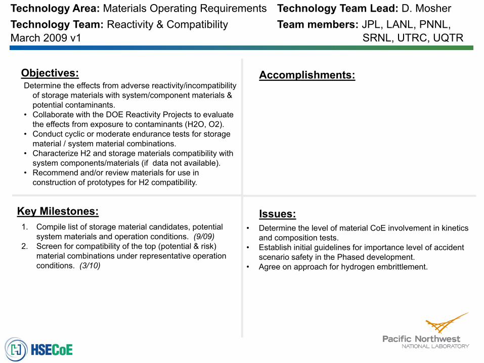
Technology Area: Materials Operating Requirements Technology Team Lead: D. MosherTechnology Team: Reactivity & Compatibility Team members: JPL, LANL, PNNL, March 2009 v1
Objectives: Accomplishments:
Key Milestones: Issues:• Determine the level of material CoE involvement in kinetics
and composition tests.• Establish initial guidelines for importance level of accident
scenario safety in the Phased development.• Agree on approach for hydrogen embrittlement.
Determine the effects from adverse reactivity/incompatibility of storage materials with system/component materials & potential contaminants.
• Collaborate with the DOE Reactivity Projects to evaluate the effects from exposure to contaminants (H2O, O2).
• Conduct cyclic or moderate endurance tests for storage material / system material combinations.
• Characterize H2 and storage materials compatibility with system components/materials (if data not available).
• Recommend and/or review materials for use in construction of prototypes for H2 compatibility.
SRNL, UTRC, UQTR

1. Develop adsorbent selection criteria (4/09)2. Indentify materials properties needed for center
modeling and engineering activities (4/09)3. Establish who, what, when for property characterization
measurements (4/09)4. Model base line adsorption (5/09)5. Survey available adsorbents (5/09)6. Down select candidate (6/09)
Technology Area: Materials Requirements Technology Team Lead: R. ChahineTechnology Team: Materials Properties: Adsorbents Team members: BASF, Ford, GM March 2009 v1 NREL, UQTR
Objectives: Accomplishments:
Key Milestones: Issues:• Need to establish proper distribution of measurement tasks• Availability of analytical resource (equipment, etc) • Material availability for evaluation, or information to
synthesize materials
• Develop selection criteria and down select base adsorbent
• Develop initial base line model• Establish materials properties database for use in
modeling and system engineering by HSECoE partners• Perform initial screening tests (calorimetry, kinetics,
composition) for storage system materials• Produce material characterization and generate
engineering property data base• Model H2 uptake (serves also for metering)• Derive Heat of adsorption

1. Develop metal hydride selection criteria (4/09)2. Indentify materials properties needed for center
modeling and engineering activities (4/09)3. Establish who, what, when for property characterization
measurements (4/09)4. Identify baseline model for screening and down
selection of material options (5/09)
Technology Area: Materials Requirements Technology Team Lead: T. MotykaTechnology Team: Materials Prop’s: Metal Hydride Team members: GM, SRNL, UTRC March 2009 v1
Objectives: Accomplishments:
Key Milestones: Issues:• Need to establish proper distribution of measurement tasks• Availability of analytical resource (equipment, etc) • Material availability for evaluation, or information to
synthesize materials
• Develop selection criteria and down select base adsorbent
• Develop initial base line model• Establish materials properties database for use in
modeling and system engineering by HSECoE partners• Perform initial screening tests (calorimetry, kinetics,
composition) for storage system materials• Produce material characterization and generate
engineering property data base
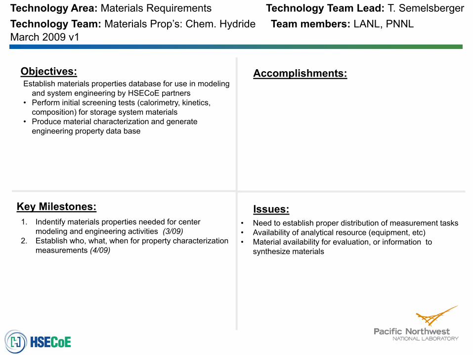
1. Indentify materials properties needed for center modeling and engineering activities (3/09)
2. Establish who, what, when for property characterization measurements (4/09)
Technology Area: Materials Requirements Technology Team Lead: T. SemelsbergerTechnology Team: Materials Prop’s: Chem. Hydride Team members: LANL, PNNL March 2009 v1
Objectives: Accomplishments:
Key Milestones: Issues:• Need to establish proper distribution of measurement tasks• Availability of analytical resource (equipment, etc) • Material availability for evaluation, or information to
synthesize materials
Establish materials properties database for use in modeling and system engineering by HSECoE partners
• Perform initial screening tests (calorimetry, kinetics, composition) for storage system materials
• Produce material characterization and generate engineering property data base

PNNL Technical Scope Objectives
Demonstrate high level of performance that meets DOE 2015 targets using solid chemical hydrogen storageOptimize design of structured storage bed and system performanceReduce system volume and weight and optimize system storage capability, fueling, and dehydriding performance Mitigate materials incompatibility issues associated with hydrogen embrittlement, corrosion, and permeability Demonstrate the performance of economical, compact, lightweight vessels for a hybridized storage Guide design and technology down selection through cost modeling and manufacturing analysis
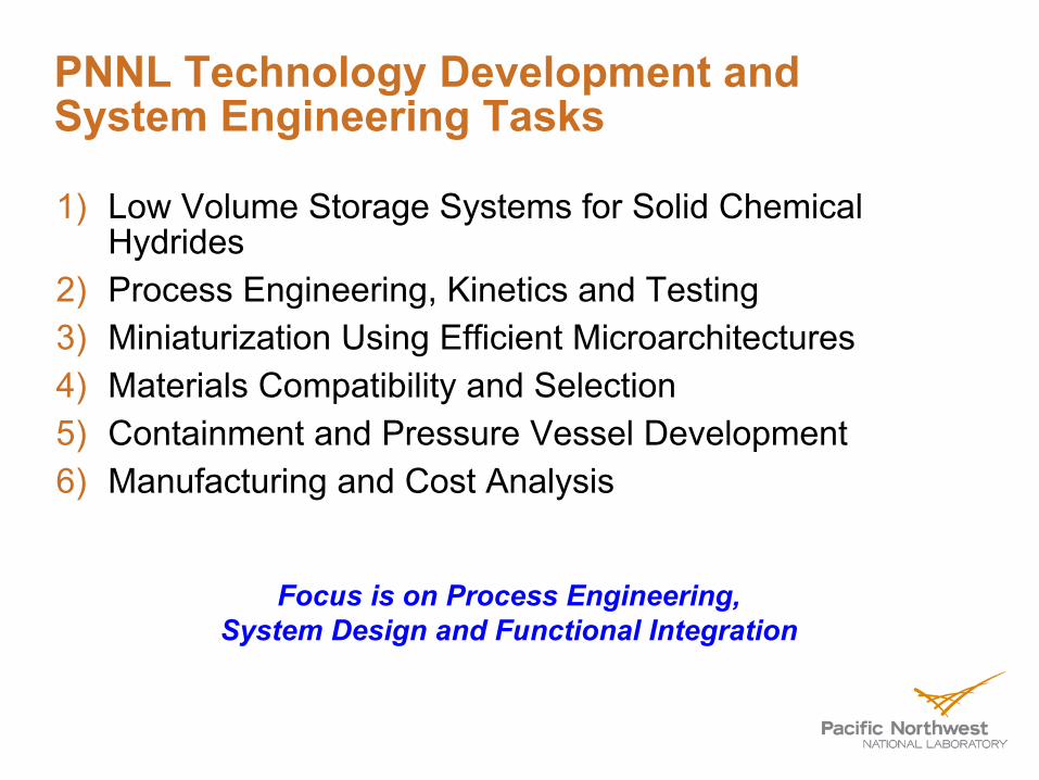
PNNL Technology Development andSystem Engineering Tasks
1) Low Volume Storage Systems for Solid Chemical Hydrides
2) Process Engineering, Kinetics and Testing 3) Miniaturization Using Efficient Microarchitectures4) Materials Compatibility and Selection5) Containment and Pressure Vessel Development6) Manufacturing and Cost Analysis
Focus is on Process Engineering, System Design and Functional Integration

NH BH (3)
Hydrogen Densities of Materials
0
50
100
150
200
0 5 10 15 20 25 30Hydrogen mass density (mass %)
Hyd
roge
n vo
lum
e de
nsity
(kgH
2m
-3)
100
liquidhydrogen
700 bar
350 bar
CH4 (liq)
C2H5OH
C8H18
C3H8
C2H6NH3
CH3OH
Mg2NH4
LaNi5H6
FeTiH1.7
MgH2
KBH4
NaAlH4
NaBH4
LiAlH4
LiBH4
AlH3TiH2
CaH2
NaH
2015 system targets
2010 system targets
3 3
NH3BH3(2)
NH3BH3(1)
Mg(OMe)2.H2O
11M aq NaBH4
hexahydrotriazine
decaborane
LiNH2(2)
LiNH2(1)
NH4BH4(4)
Courtesy of G. Thomas
Ammonia Borane Shows Promise

Primary Engineering Barriers forChemical Hydride Systems
Chemical Hydrides are Not ‘Reacted’ in the Fuel TankAB thermolysis at <100°C, but how will AB respond to storage in hot climates?Solids handling engineering part of any system concept
DOE Technical Targets:Maximum Operating Ambient Temperature: 50°C (2010) & 60°C (2015)“No allowable performance degradation … to 40°C” Loss of Useable Hydrogen (g/hr)/kg H2 stored: 0.1 (2010) & 0.05 (2015); loss includes venting, if required
Ammonia Borane foams on reaction – potential limitation to practical engineering applicationPerformance impact of contaminants and volatile byproducts?

Engineered Form-Factor for Solid AB
System targets are difficult for granulated materialsAB foams when it releases hydrogen – not conducive to engineeringAntifoaming approaches key
More than 50 additive formulations tested with 2-3 successful (CHCoE study)Scaffold materials also demonstrate foam suppression at lower AB:scaffold loadings Paves way for system with monolithic fuel & high volumetric density
0.03
0.04
0.05
0.06
0.07
0.08
0.09
0.1
0.11
0.1 0.2 0.3 0.4 0.5 0.6
Bed Void Fraction
Volu
met
ric C
apac
ity, k
g H
2/L
2 Equiv. H2 from AB (13.1 wt%)
SingleCrystal
2010 System
2015System
Close-PackedSpheres
LoosePowder
Additive suppresses foaming and enables monolithic fuels
Source: PNNL CHCoE

AB Thermal Stability Calculations –Assumptions and Insight
1st equivalent only –Avrami kinetics70-90 °C isothermal DSC data* used for initial fit of parametersAdiabatic assumed as a worst caseModel AB bed properties
1000 mol AB = 4 kg H2(2 H2 equiv.)6.0 wt% H2 in a storage unit including >50 wt% structure No temperature gradients
Extrapolation of DSC Data to Lower Isothermal Temperatures
*Wolf et al., Thermochimica Acta 343, (2000) 19Source: PNNL CHCoE
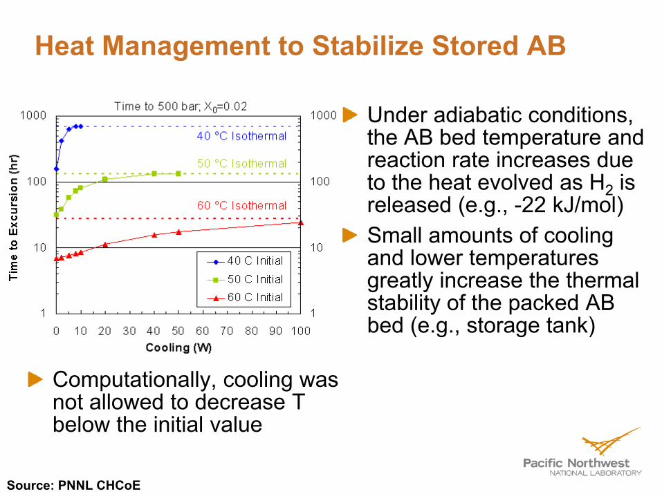
Heat Management to Stabilize Stored AB
Computationally, cooling was not allowed to decrease T below the initial value
Under adiabatic conditions, the AB bed temperature and reaction rate increases due to the heat evolved as H2 is released (e.g., -22 kJ/mol)Small amounts of cooling and lower temperatures greatly increase the thermal stability of the packed AB bed (e.g., storage tank)
Source: PNNL CHCoE

Importance of Hydrogen Purity
Fuel cell activity degrades quickly when switching from bottled hydrogen to hydrogen from AB fuel storage sourceAfter deactivation activity recovered when run on bottled H2
Membrane does not appear to suffer damageFiltration/separation can be used to run fuel cell on AB fuel
Courtesy of LANL: Semelsberger, Borup

Low Volume Storage for Solid Chemical Hydrides (Task 1)
Chemical hydride system design and performance modelingSolids handling design for monolithic fuelChemical reactor engineering and prototyping
Flow chart indicating how monolithic fuel might be cycled within a chemical hydrogen fueling system to reduce impact on total volume.

Process Engineering, Kinetics and Testing (Task 2)
Process modeling and engineeringSystems component integration and testingSystem and bulk materials kinetics
Release curves for AB (above) and predicted fueling rate requirement to meet US DOE target of 0.01 mol H2/s/kW for an 80 kW fuel cell (left)

System Miniaturization Using Efficient Microarchitectures (Task 3)
Balance of plant component model and designMicrochannel device model and design
Heat exchangers (tank internal/external)Other chemical/thermal devices
Microchannel device fabricationMicrochannel device testing
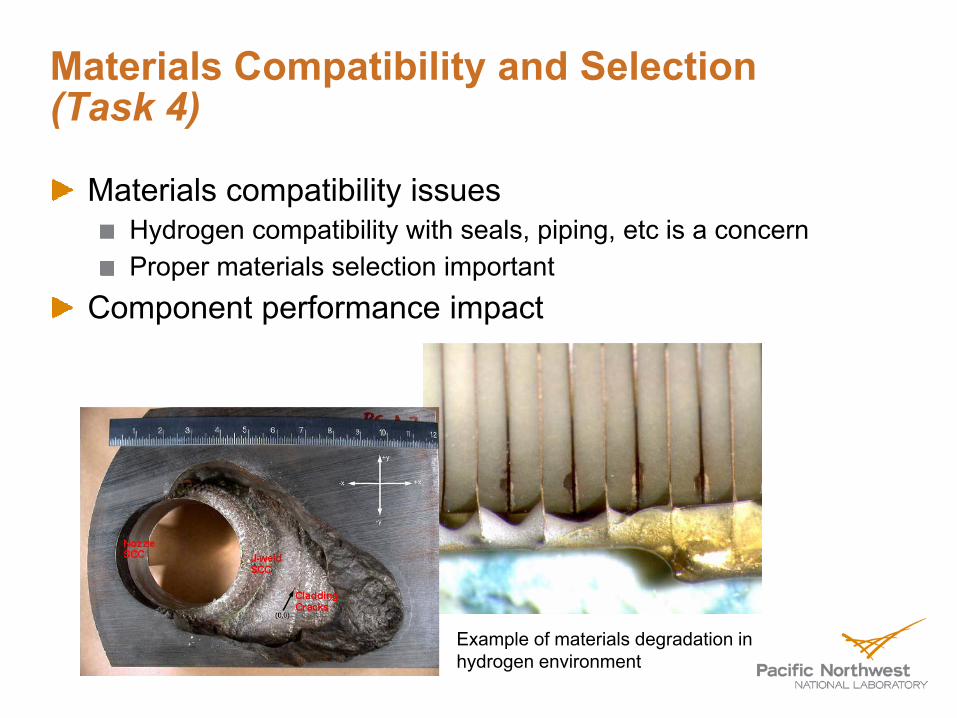
Materials Compatibility and Selection(Task 4)
Materials compatibility issuesHydrogen compatibility with seals, piping, etc is a concernProper materials selection important
Component performance impact
Example of materials degradation in hydrogen environment

Containment and Pressure Vessel Development (Task 5)
Hybrid pressure vessel integrationHybrid pressure vessel fabricationHeat exchanger and pressure vessel integration
Coolant,Heat
Exchanger/Pipe
A
A
H2
A
A

Manufacturing and Cost Analysis(Task 6)
Cost ModelingTechnology analysis and tradeoff studyEnergy efficiency and performance impact

SummaryGoal
To develop and demonstrate low-cost, high-performing, on-board solid-state hydrogen storage through a fully integrated systems design and engineering approach.
ApproachAdvance the state of chemisorbed and physisorbed hydrogen storage systems through process engineering and application of novel component design and systems integration, facilitated through better understanding of material/system requirements and properties, plus modeling and simulation assessments.
Accomplished throughSeries of technical tasks, coupled by close collaboration with HSECoE partners, that address the main project objectives. Primary emphasis is on chemical hydride systems, with secondary efforts supporting adsorbant and metal hydride systems design.

PNNL Work Breakdown Structure
M = Milestone; D = Deliverable; G = Go/No-Go
Phase 1 Phase 2 Phase 3 2009 (Q) 2010 (Q) 2011 (Q) 2012 (Q) 2013 (Q) PNNL
Task No. Subtask Title 1 2 3 4 1 2 3 4 1 2 3 4 1 2 3 4 1 2 3 4 1.1 Chemical hydride system design and
performance modeling M1 M3 G5 M17
1.2 Solids handling design for monolithic fuel M2 G1 G6
2.1 Chemical reactor engineering M4 G7 2.2 Chemical reactor fabrication M14 D3 2.3 Chemical hydride component testing M16 2.4 System and bulk materials kinetics M5 M11 3.1 Microchannel heat exchanger model
and design M6 M12 G8
3.2 Microchannel device fabrication D4 3.3 Microchannel device testing G9 D5 3.4 Balance of plant component model
and design M7 M13 G10
4.1 Materials compatibility issues and component performance impact M8 M15
5.1 Hybrid pressure vessel architecture model and design M9 G3
5.2 Hybrid pressure vessel fabrication D6 5.3 Heat exchanger and pressure vessel
integration M10 G4
6.1 Cost modeling D1 G11 6.2 Technology analysis and tradeoff
study G2 D2 G12
6.3 Energy efficiency and performance G13 Quarterly reports Annual reporting Report Annual merit reviews

FY 2009 Activities and DeliverablesActivities
Construct a heat/mass transfer model that will be use to simulate hydrogen release in monolithic fuels in order to guide system design. (Task 1)Complete a conceptual design for a solid chemical hydride reactor that will provide input to the HSECoE’s Phase 1 Go/No-go decision making process. (Task 2)Develop model for heat exchange using microarchitecture devices for chemisorption and physisorption systems. (Task 3)Development of modeling approach, assumptions, and basic model structure to simulate various pressure vessel geometries and layered structures. (Task 5)Create first revision of cost model, structure details and spreadsheet for the evaluation cost of technologies and systems components for assistance in down selection. (Task 6)
Deliverables & MilestonesFormal quarterly/annual reportsDetermination potential for achieving H2 release rate target of 1.6 g H2/s for an 80 kW fuel cell. (Q4, FY2009)Provide insight, through conceptual design and modeling efforts, into the ability of such a system to meet the 2010 volumetric capacity target of 1.5 kWh/L. (Q3, FY2009)Establish basic heat exchanger requirements for each of the 3 hydride systems and initiate model development. (Q3, FY2009)Establish the modeling approach, assumptions, and basic model structure to simulate various pressure vessel geometries and layered structures, including model parameters that account for basic cost and performance. (Q3, FY2009)Provide Rev.0 cost model, structure details and spreadsheet to Center partners for their evaluation. (Q4, FY2009)

Key Project Staff: PNNL
Solid Chem. Hydride System
Scott RassatBrian KoeppelChris Aardahl
Kinetics & Storage Mat’ls
Ewa RonnebroAbhi KarkamakarDaiwon Choi
PNNL Principal Investigator
Darrell Herling
Pressure Vessel & Materials
Kevin SimmonsKen JohnsonSachin Laddha
Manufacturing & Cost Analysis
Todd SamuelMark Weimar
Process Engring & Microtech
Dale KingJames DavisGreg WhyattPaul Humble

PNNL customers count on expertise to help define the future and…
$1.1 billion in 2008 sales61% of annual sales support DOE missions
Fundamental ScienceEnergyEnvironmentNational Security
…deliver science, technologies, and leadership

Darrell Herling – Pacific Northwest National Lab, Principal [email protected], (509) 375‐6905
Don Anton – HSECoE, Director Monterey Gardiner – DOE EERE, Technology Development Manager