system7 - sius · system7 sius ag im langhag 1 ch-8307 effretikon switzerland ... system 7 user...
TRANSCRIPT

System 7 Art.Nr.BASYS7ER2 - 1 - © by SIUS AG / 21/03/16
Electronic Targets
User ManualSystem7
SIUS AGIm Langhag 1CH-8307 EffretikonSwitzerlandTel.: +41 (0)52 354 60 60Fax: +41 (0)52 354 60 66Internet: http://www.sius.comE-Mail: [email protected]

Electronic Scoring System SA941/SA9004
System 7 Art.Nr.BASYS7ER2 - 2 - © by SIUS AG / 21/03/16
Contents1 About this Manual ........................................................................................................ 4
1.1 How to find Information .................................................................................. 41.2 How to contact Sius AG ................................................................................. 41.3 TypographicConventions................................................................................ 5
2 Getting started.............................................................................................................. 62.1 Connecting and turning on Devices................................................................ 62.2 Connect Target .............................................................................................. 8
2.2.1 More than one Control Unit on the same Network ...................................102.3 Set Language................................................................................................122.4 Set Discipline ................................................................................................13
3 Display Overview.........................................................................................................143.1 Windows Layout............................................................................................143.2 Contents of Windows ....................................................................................15
3.2.1 Target Window ........................................................................................153.2.2 Shot Windows .........................................................................................163.2.3 List Window.............................................................................................173.2.4 Progress Window ....................................................................................183.2.5 Statistics Window ....................................................................................183.2.6 Selection Window....................................................................................193.2.7 Status Window ........................................................................................193.2.8 Title Bar...................................................................................................203.2.9 Function Key Bar.....................................................................................20
4 Concepts......................................................................................................................214.1 Usage........................................................Fehler! Textmarke nicht definiert.
4.1.1 Menu (Using the Keyboard).....................................................................214.1.2 Barcodes .................................................................................................244.1.3 PC ...........................................................................................................25
4.2 Settings .........................................................................................................254.3 Filters ............................................................................................................264.4 Program Types..............................................................................................27
4.4.1 Control Menu...........................................................................................284.4.2 Targets (Free Series) .............................................................................284.4.3 Fixed Programs .......................................................................................314.4.4 User Programs ........................................................................................324.4.5 Match (ISSF) ...........................................................................................33
4.5 Special Disciplines: 25 meters.......................................................................344.5.1 Centre Fire – and Sport Pistols................................................................344.5.2 Standard and Rapid Fire Pistols ..............................................................35
4.6 Timer.............................................................................................................354.7 Communication .............................................................................................36
5 Maintenance ................................................................................................................375.1 Reports .........................................................................................................37
5.1.1 Settings ...................................................................................................375.1.2 Shot Report .............................................................................................385.1.3 Program Settings.....................................................................................38
5.2 Log................................................................................................................395.3 Target Test....................................................................................................40
6 Devices ........................................................................................................................426.1 Scoreboard (SCB).........................................................................................426.2 LON-Measurement Electronic System (LME) ................................................436.3 LNR-Box (Lane Number Box)........................................................................43

Electronic Scoring System SA941/SA9004
3
6.4 Time Control Unit (TCU)................................................................................436.5 Computer (PC) ..............................................................................................456.6 Printers (D93, D941) .....................................................................................46
6.6.1 Self Test ..................................................................................................466.6.2 Date Buffer ..............................................................................................46
6.7 Barcode Scanner (BCR Reader) ...................................................................466.8 Control Unit (CU941, Control Unit, Handheld, ME)........................................47
6.8.1 Components............................................................................................476.8.2 Startup Functions ....................................................................................47
6.9 Shot Sensor (SAB, C88) ...............................................................................486.10 Mechanical Shot Counter ..............................................................................496.11 Remot Control (RC941, RC-ZOOM).............................................................50
6.11.1 Zoom Key (Enter) ....................................................................................506.11.2 Menu Key ................................................................................................516.11.3 Match Key ...............................................................................................51
7 Appendix......................................................................................................................527.1 Separate Document ......................................................................................527.2 Frequently Asked Questions (FAQ)...............................................................537.3 Short Explanations ........................................................................................54

Electronic Scoring System SA941/SA9004
4
1 About this Manual1.1 How to find InformationThis manual contains basic information about the product lines SA941 and SA9004 ofSIUS AG.
You can search for information by means of the list of contents or the glossary (tables,illustrations, drawings and word glossary) in the appendix to this document.
Additionally there is a separate document "Appendix to the System 7 User Manual". Thisdocument lists and explains all the targets, programs, settings and commands for theequipment.
Up to date information can be found on our web site: www.sius.com.
1.2 How to contact SIUS AGInformation type Switzerland Worldwide
Sales & Administration +41 (52) 354 60 60 Representatives Listwww.sius.comTechnical Support +41 (52) 354 60 60
Table 1 Sius AG Addresses

Electronic Scoring System SA941/SA9004
5
1.3 TypographicConventionsThis document has been produced using the following conventions:
Visual Representation Meaning"Italic font in quotes“ Reference to another document.
Italic Bold font in quotes separated withbackslashes:"\System\Hardware\Control Unit"
Menu path via the keyboard to access acommand or setting on the control unit.
Framed texts, stepped: Menu path via the keyboard to access acommand or setting on the control unit.
Framed Font:
Enter -Taste
Description of a key on the control unitkeyboard.
Important information: This arrow points to information meritingparticular attention.
Courier fontPractice...... Start:
13:07:09.99
Print outs from a printer (D112) connected toa control unit.
Numeration in brackets:(Chapter 3.2.3 Designation)
Reference to a chapter in this document.
Words in capital and in quotes
„OFFLINE“
Reference to a status of the control unit. Thestatus is displayed in the status window.
Table 2 Typographics Conventions
Monitor Hardware
System

Electronic Scoring System SA941/SA9004
6
2 Getting started2.1 Connecting and turning on DevicesIn order to use an Electronic Scoring System, at least one control unit, one monitor and onedetection system have to be connected and supplied with power.
Figure 1 Example Devices

Electronic Scoring System SA941/SA9004
7
Monitor
The Monitor, depending on the model, must be switched on by its own power switch.Please make sure that the Brightness Control on the underside of the equipment isset to the central position.
At least the following cables must be connected:
Figure 2 Minimal Cabling
N°. Device Connection to Description1 Control Unit Power Supply Power Supply (e.g. by RJ45 cable)
2 Control Unit Detektion System Communication Cable(RJ45 sockets)
3 Monitor Control Unit Video Cable (VGA)
4 Monitor Power Supply Power supply cable or special powersupply cables for M94
Table 3 Minimal Cabling (Connections)
4
3
21
Power Supply
Control Unit
Detektion System

Electronic Scoring System SA941/SA9004
8
After turning on and starting up the control unit for the first time the screen should show thefollowing content:The version details (Main V7.0i etc.) will differ from the example:
Figure 3 Screen Display after First Startup
2.2 Connect the TargetIf there isn’t a target connected to the control unit the status changes to “OFFLINE” (after 2minutes at the latest). Thus the target has to be configured to the correspondent control unit.If the target features a rotary control for configuration (LS10/HS10/HS2550/LS10G2 andsome LME), programme the subnet address to the corresponding lane number und the nodeto 0 (zero). After a re-start of the target it will be connected to the control unit. Therefore thestatus changes to “STOP” or “READY”.Doesn’t the target feature these rotary controls it has to be programmed via service-pin. Forthat use the following command:„\System\Hardware\Target\Connect“
System
Hardware
Target
Connect

Electronic Scoring System SA941/SA9004
9
The framed text represents the menu points of the LCD-Menu. They can beselected by pressing the corresponding function keys. The "\System" directory
can be accessed by pressing the FF 44 function key. By doing so, the content of theLCD-Menu changes. Now the "\...\Hardware" directory is displayed under the
function key FF 44 . By pressing the FF 44 function key you can switch tothe"\Hardware" directory.
By pressing the EE ss cc key you can move up one directory level.
By pressing the HH oo mm ee key you can return to the home directory at any time.
As an alternative to the keyboard, you can enter this command by reading the followingbarcode with the barcode scanner:
System\Hardware\Target\Connection
9 9 0 6 3 2 0 0 6 7
Figure 4 Connect Target Function
This barcode switches the control unit to a special configuration mode. The control unit waitsfor a service PIN message from any LON Measurement Electronic System. This messagecan be created on the target, either when the service PIN is pressed or when shooting takesplace. However, a shot only triggers a Service PIN message if the target was not previouslyconfigured. The one target that first reports this Service PIN message is reprogrammed bythe control unit to its own target number.
The following text is displayed in the list window:
Figure 5 Connect Target

Electronic Scoring System SA941/SA9004
10
Press the Service Pin button (small round blue button) on the LON Measurement Electronic(LME) System for 1 second and release it again.
Figure 6 LON Measurement Electronic System with Service PIN
The control unit then confirms the successful configuration with a beep and a message in thelist window. At the same time the status switches from "OFFLINE" to "STOP“.
Figure 7 Target Connected
2.2.1 More than one Control Unit on the same Network
If you need to configure several control units, all the subnet addresses of thecontrol units have to be set first. Afterwards connect one lane after another.Please make sure that only one control unit at the time is waiting for the "ServicePin" message.
If there are more than one control units connected to the same network, all subnet addressesof the devices have to be set individually. The lane number (subnet address), which isdisplayed in the upper left corner of the monitor, has to be unique for all control units.Tochange or set the lane number (subnet address) choose the following directory via thekeyboard menu:
RJ45
Stecker
Leuchtdioden Service-Pin
Plug
Light Emitting Diode Service PinRJ45

Electronic Scoring System SA941/SA9004
11
"\System\Hardware\Control Unit\Set Subnet"
Due to this command, an edit field appears on the LCD of the control unit. The target number(Subnet Address) (can be entered via the membrane keyboard. The target number has to be
between 1 and 253. Press the Enter key to confirm your input or press the Esc key to cancel.
As an alternative to the keyboard, you can enter the subnet addresses by reading thefollowing barcode with the barcode scanner:
Subnet Barcode
1
…Hardware\Control Unit\Set Subnet\1..9\1
9 9 0 7 2 7 0 0 0 1 5 8
2
…Hardware\ Control Unit\Set Subnet\1..9\2
9 9 0 7 2 7 0 0 0 2 5 5
3
…Hardware\ Control Unit\Set Subnet\1..9\3
9 9 0 7 2 7 0 0 0 3 5 2
4
…Hardware\ Control Unit\Set Subnet\1..9\4
9 9 0 7 2 7 0 0 0 4 4 9
Table 4 Barcodes set subnet on control unit
Further barcodes for other subnet addresses can be found in the "Appendix to the System 7User Manual".
System Hardware
Control unit Set Subnet

Electronic Scoring System SA941/SA9004
12
2.3 Set Language
The most important setting on the control unit is the language. This setting can again beselected by the keyboard or the barcode scanner. This setting can be accessed under:
"\System\Settings\Language"
Although there are barcodes to change or set language (to be found in the "Appendix to theSystem 7 User Manual") we do not recommend to use them in connection with the controlunit CU941 as there are differences in the implemented languages and their controldepending on the software used.By controlling via the keyboard menu only the available languages can be chosen.
System
Settings
Language (ENG)

Electronic Scoring System SA941/SA9004
13
2.4 Set Discipline
The complete program and target catalogue with all the corresponding barcodes can befound in the "Appendix to the System 7 User Manual". Four examples are listed here so thatthe function can be tested:
After the power supply has been turned on, it is important to wait one minutebefore shooting begins so that all the devices are correctly synchronised. (If not, itis possible that shots are marked as illegal.
Target Description Barcode
Example 1: 10m Pistol
"\Targets\10m\ISSF\Pistol"
0 6 0 0 0 0 1 9 0 0 0 2 0 3 5 6
Example 2: 50m Rifle
"\Targets\50m\ISSF\Rifle"
0 6 0 0 0 0 1 9 0 0 0 3 0 1 5 3
Example 3: 300m A10
"\Targets\300m\ISSF\A10"
0 6 0 0 0 0 1 9 0 0 0 0 0 2 7 7
Example 4: Hunting
"\Targets\Other\Hunting\Chamois"
0 6 0 0 0 0 1 9 0 0 0 1 0 8 5 0
Table 5 Program Examples

Electronic Scoring System SA941/SA9004
14
3 Display Overview3.1 Screen Layout
Information on shooting in progress is divided into several windows on the control unit.
Figure 8 Screen Layout
The layout of the screen can be changed in the "Layout" settings. The factory setting is"Classic" display. With the "Stop Left" and "Final" settings, the display layout can be set tothe needs of the marksmen and spectators.
Target Number (Subnet-Address)
Titel Bar (3.2.8) Current Date and Time
List Window (3.2.3)
Shot Window (3.2.2)
Practice ProgressWindow (3.2.4)
Next Window
Target Window (3.2.1)
Selection Window (3.2.6)
Status Window (3.2.7)
Statistics Window (3.2.5)
Function Key Window (3.2.9)

Electronic Scoring System SA941/SA9004
15
3.2 Contents of Windows3.2.1 Target Window
The target window shows the target name, the target image, the shooting situation and otherstatus information.
Figure 9 Target Image
In brackets to the right of the target name you can see the types of score method(s) (i.e.primary and secondary score; these often correspond to the qualification score in whole tensor the final score in tenths). If, as shown in the example, the calibre information indicates acenter score, then the calibre settings have no effect on the shot value. The shot value inthese score methods is calculated independently of the calibre which has been set. Thedisplay of the target name and the score calculations can be switched off via the settings.
The sighters triangle indicates that the type of fire is set to "Sighters". Shots fired in this firetype are marked with a "P" and are not taken into account for the overall result.
Target Name
Score methods
Sighters Triangle
Target Image
Inner Ten Circle
Last Shot
MPI (Mean Point of Impact)
Recent Shots
Ruler

Electronic Scoring System SA941/SA9004
16
With the Zoom key, different zoom levels can be selected. The ruler changes accordingly.
The symbol for the last shot fired can be set independently of the symbol for all other shots.The symbol "Calibre" was selected for both as factory setting. The control unit shows theshot holes true to size, as long as the hole is not below a certain minimum size. On holesthat are particularly small (e.g. for 300m distances) a cross is drawn instead of a circle. Thelast shot fired is shown in inverse colour.
Various parameters such as the "Mean Point of Impact (MPI)", supplement the graphicalinformation in the target window. These parameters are optional and can be turned on or offin the parameter settings.
The "ruler" allows to estimate the target size. This helps to prevent inadvertent shooting atsimilar looking targets. The depiction of the calibre and of the ruler can be turned on and offin the settings.
Figure 10 Shot Sensor Symbol and Cross Shot Symbol
The shot sensor symbol appears in dimmed form in the lower right corner of the targetwindow as soon as a shot sensor is connected. The display changes to the cross shotsymbol if in the past seven minutes a cross shot has been fired. Cross shots can only bedetected with the connected shot sensors (chapter 6.9 Shot Sensor).
3.2.2 Shot WindowIn the shot window the last shot fired is displayed in a large font.
Figure 11 Shot Window
The number on the left shows the shot number. "P" stands for “sighters shot”. The number inthe middle is the primary score and the number on the right is the secondary score. In ourexample it is the 10th ring score. The layout of the shot window can be changed via severalsetting options.

Electronic Scoring System SA941/SA9004
17
3.2.3 List WindowThe list window displays all shots, various totals and other information.
Figure 12 List Window
The number on the left shows the shot number. Sighters shots are numbered individually.The arrow shows the shot position from the target centre. The primary and the secondaryscores are next. The display of the secondary score is optional and can be suppressed.
The flag on the right of the number 10 shows that it is an inner ten. On the printout the innerten is marked with "*". The "P" (Probeschuss = Sighters Shot) with the first three shots showsthat they were fired as sighters shots.
Shots can have the following attributes.
Symbol Meaning
Direction
(12.2 / -4.8) Shot coordinates in millimeters
11:33:17.43 Absolute time in hours: minutes: seconds and 1/100 seconds
(2.5s) Relative time from the 1st shot of the group or overtime information on 25meter disciplines
Inner ten
! = Demo ShotP = Sighters Shot
(Frame-Hit)
Miss Miss (shot off signal without shot on; see shot sensor)
97 !P

Electronic Scoring System SA941/SA9004
18
Symbol MeaningCross Shot Cross Shot; see (Chapter 6.9 Shot Sensor)
/ Direction (Sweep; Running Target)
S / L Fast/Slow (Running Target)
OT Over Time
NAMf Non-Allowable Malfunction
Table 6 Shot Attributes
3.2.4 Progress Window
The Progress Window is visible as an option. It can be turned on or off in the settings.
Figure 13 Practice Progress Window
The content of the progress window depends on the chosen discipline. In our example a"pre-programmed discipline" is shown in which the number of shots is fixed. The active grouphas a white background. The ">>" symbol shows that there are more groups to follow the"D2" group. The display is similar for user programs and for matches. In free program seriesonly three fire types are shown: P (Probe = Sighters), S (Shot by Shot) and D (Deferred). Thefire type can be selected optionally and the number of shots is not fixed. See (Chapter 4.4Program Types)
3.2.5 Statistics Window
The Statistics Window shows various information on the current program shot.
Figure 14 Statistic Window
Depending on the parameters set, the content of the statistics window will change. The"Mean Point of Impact " (MPI)" is shown graphically in the target window and appears as textin the statistics window. The arrows show the position of the MPI and the figures give thedistance to the target centre in millimetres. Each parameter has its own form of display.Further explanation can be found under the respective parameters in the "Appendix to theSystem 7 User Manual".
P- S5 P- S5 D2
MPI (5 Shots)4.14.4

Electronic Scoring System SA941/SA9004
19
3.2.6 Selection WindowThe selection window displays the selected program and full information on the firer.
Figure 15 Selection Window
Additionally, information on the position and the weapon can be listed. In the example, thefirer number and the selected program are shown.
3.2.7 Status WindowThe status window shows whether the system is ready for shooting.
Figure 16 Status Window
Several significant statuses are differentiated:
Status Meaning“READY“ A program has been selected. The target has been detected
and is ready. The system is ready for shooting. After asystem start-up it is important to wait one minute at leastbefore shooting begins. The control units require this time toensure that all the connected devices are correctlysynchronised. (
“STOP“ The control unit has been restarted or the last program hasfinished. Shooting may neither start nor continue. Shots firedduring the stop phase are declared illegal.
“SHOW“ A series with several shots has been fired. The shots are nowshown one after another. During the show phase no shootingmay take place. Shots fired during the show phase aredeclared illegal.
“OFFLINE“ The control unit switches to „OFFLINE“ when no target withthe correct target number (subnet address) have beenidentified. Either the target is connected incorrectly or theincorrect target number has been programmed.How to reset the LON Measurement Electronic System to thecorrect target number is described in (Chapter 2.2 ConnectTarget) and in the "Appendix to the System 7 User Manual"under "System\Hardware\Target\Connect".
“PAUSE“ In ISSF programs the system switches on "PAUSE" aftereach position. The firer can change to the next position withthe RC941 (Match Button) or the keyboard.
“RECOVERY“ After a power supply interruption the control units restartautomatically. If the last program shot has not been endedcorrectly, then the program that was still open is recovered.The competition can then be continued from where it wasinterrupted.
Table 7 Status Overview
Free Series156944
ReadyDemo

Electronic Scoring System SA941/SA9004
20
The following additional statuses may be displayed in small font:
Status Description“DEMO“ The control unit is in demonstration mode. With the Ins key
demo shots can be requested from the LON MeasurementElectronic System. Demo shots are marked with anexclamation mark "!" on the screen and on the printout.
“PRACTICE CONTROL“ The control unit is in a special remote control mode. Thismode is used for commanded shooting.In this mode a "PAUSE" status can only be terminated from acentral computer.
“REMOTE“ The control unit is in remote control mode. It is no longerpossible to control the unit via a keyboard or a barcodescanner.
Table 8 Status Overview 2
3.2.8 Title Bar
The target number, the current date and the time are displayed on the title bar. The dateformat can be modified.
Figure 17 Titel Bar
The target number must be between 1 and 253. If several control units are connected in thesame network, they must be differentiated by target number.
3.2.9 Function Key Bar
The function keys F1 to F5 have different tasks. The keys can be used differently dependingon which status the control unit is set to.Control >>Serie Hardcopy Others
Figure 18 Funktion Key Bar
The same information is displayed in the function key window as on the LCD Menu of thekeyboard. However, the LCD is limited to four symbols per function key (see the abbreviationglossary in the "Appendix to the System 7 User Manual". The chapter 4.1 Handling describesthe navigation through the menu).
Line 57 7/23/2009 14:43

Electronic Scoring System SA941/SA9004
21
4 Concepts4.1 Handling
The control unit can be operated in several different ways. Using the keyboard is the mostconvenient. All functions offered by the control unit can be accessed via the keyboard. Theuser programs are the only exception as they have to be loaded via a barcode scanner orfrom the central computer.
Using barcodes offers big advantages, especially for inexperienced users. This way the mostimportant commands can be collected onto one sheet of paper and the handling can besimplified essentially. This helps to prevent mishandling on a range with multiple shootingpoints.
On major commanded competitions the control units can best be controlled from a centralcomputer. This ensures that all participants operate under the same conditions. Furthermore,a central processor enables efficient data collection.
4.1.1 Menu (Using the Keyboard)
The menu has a tree structure. Similar to a modern computer system, all the elements arestored in directories and folders (commands). The root (Home) is in the centre of the menuoverview. The different directories branch out from Home. The further the branches extend inthe directories, the more detailed the information and commands become.
The complete structure of the menu is printed as an overview in the "Appendix to the System7 User Manual". This structure also corresponds to the index of barcode descriptions. Thefollowing keys are used for navigation within the menu:

Electronic Scoring System SA941/SA9004
22
Figure 19 Menu Navigation
Taste Name Beschreibung
F1 ... F5 Function Key The function keys allow to go into subdirectories or tocarry out commands
Home HomeThe Home key takes you directly back to the Homedirectory.
You can also toggle between the Home- and the
control directory with the Home key.
Esc EscapeWith the Esc key you can exit from a directory andmove up one step in the menu.
Home
F2F4 EscEsc Home

Electronic Scoring System SA941/SA9004
23
Opt OptionYou can return to the last command used via the Optkey. Frequently used commands can be accessed veryeffectively this way. You can go back to the previous
menu by pressing the Opt key again. You can also
press the Home key to go back to the Home directory.
Help HelpBy pressing the Help key you can display and print outthe address and the telephone number of SIUS AG aswell as information about the software and hardwareversions in use. Please keep this printout on hand ifyou call SIUS AG for assistance.
Next Window Next Window If there are more than 5 commands available in amenu window (directory), you can access command
number six and above by pressing the Next Windowkey. The ">>" symbol is displayed on the screen and inthe menu to indicate that there are further commands
available. Pressing the Next Window key will take youback to the first menu window.
Enter Enter Some settings can be edited with the number keys onthe keyboard. For example, the firer number can beinserted via the number keys. These inputs can be
confirmed with the Enter key or cancelled with the Esckey.
UP “ ˄ “Move Up
Using the Up key, the second to last shot in a programthat has been shot can be called up once more. In thisway all previous shots can be discussed.
Down “ ˅ “Move Down
The Down key takes the discussion in the otherdirection.
Ins Insert If the system is in Demo Mode (Demo is displayed in asmall font on the bottom right of the Status Window),you can then generate demo shots on the target by
pressing the Ins key. This allows the system to betested without actual shooting taking place.
Demo shots are always marked with "!" in the listwindow and on the printout. Thus they can be easilydistinguished.
Table 9 Keyboard Functions
When a discipline has been selected, the menu switches automatically to the control menu.In the control menu, all the commands which can be called up for the chosen program areimmediately available. See (Chapter 4.4 Program Types).

Electronic Scoring System SA941/SA9004
24
4.1.2 Barcodes
Figure 20 Barcode Scanner
To scan a barcode, put the barcode scanner straight onto the code you want toscan and lift the scanner one to two centimetres. Press the scan button.
High quality printouts and copies of the barcodes must be used. The control unit confirms scanned barcodes with different beep signals. One beep
means a valid scanned barcode. Two beeps mean that the command has beenaccepted but it cannot be put into practice or it is not supported. Three beepsindicate a scan error or an illegal barcode.
Only barcodes from the "Appendix to the System 7 User Manual" or those createdby the barcode library can be used. The use of other barcodes can result in amalfunction of the device.
The control unit (the CU941 only) is equipped with a hardware port on the right hand side toconnect a barcode scanner. The barcode scanner can carry out all the inputs that can alsobe made via the keyboard. Moreover, user programs which were previously generated by thecomputer program barcode library or with SiusData® can also be scanned.
The barcodes are organised in the same way as the keyboard menu of the control unit. Allthe available barcodes are listed in the "Appendix to the System 7 User Manual". The menucan be used as an additional list of contents.
"Interleave 2 of 5" codes are used as barcodes. The barcodes are protected with achecksum so that scan errors and incorrect codes are automatically filtered.

Electronic Scoring System SA941/SA9004
25
4.1.3 PC
With the SiusData® PC software, all commands can be sent simultaneously to all the controlunits connected to the same network. Therefore, it is very easy to simultaneously change thesame settings for all control units or download a program. Detailed information can be foundin the SiusData® documentation.
4.2 Settings
The control unit disposes of many setting options which cover almost all customer needs.Everything from language selection via the booting program to the display varieties can beconfigured. The organisation of the settings is clearly explained in the menu. The followingdiagram shows how the settings can be managed.
Hard memory(Flash)
Volatile memory(RAM)Battery buffered
Customersettings
Activesettings
Factory settings
Figure 21 Settings Management
1. Before the first use, all customer settings are set to the same value as the factorysettings.
2. At the first start-up, (Cold Start), all the customer settings are copied to the activesettings. With the command "\Settings Control\Customer Settings", all savedcustomer settings are copied again to the active settings during use. Changes to thesettings which have been made up to this point are reset.
3. With the command "\Settings Control\Save Customer Settings", the activesettings are permanently saved to the customer settings. This function ensures thatthe control unit restarts in the configuration chosen by the customer even after abattery change.
4. With the command "\Customer Settings\Factory Settings", the active settings areoverwritten again by the factory settings. The factory settings are selected so thatthey are suitable for as many users as possible. The default language is English.
The Target/Lane Number (subnet address) of the control unit is not reset to 1 bythe factory settings.
1
2
3
4

Electronic Scoring System SA941/SA9004
26
4.3 Filters
The filter settings are accessible via the following path:"\System\Settings\Other\Filter":
Figure 22 Filter Settings Path
The functionality of system 7 is very comprehensive. In contrast to previous versions, System7 covers several types of installations. It can be used for sport shooting as well as forhunting. Often, a user only wants to use one part of the functionality. The filter functions weredeveloped to be able to restrict the usage via the keyboard (menu) to just this one partnecessary.
The filter function can be explained more easily using distances as an example. In the controlunit, programs for distances of 10, 25, 50 and 300 metres are available. If a control unit ispermanently installed in the 50 metre range, however, it makes no sense for the user to beable to select the 10 metre and 300 metre options as well. A filter makes it possible to filterout the distances which are not needed.

Electronic Scoring System SA941/SA9004
27
An extract from the menu is shown below in unfiltered format:
Figure 23 Unfiltered Menu
Under the menu path "\System\Settings\Other\Filter\Distance" the 50 metre distance canbe set explicitly. All other distances are automatically masked. It is also possible to filter outmore than one distance. Any unset distances are masked. Thus, the menu in our example isreduced to:
Figure 24 Filtered Menu
If you press F1 in the Home directory, you will be taken directly to 50m, because only onesingle choice is available in the "Targets" directory. Therefore, the 50 metre ISSF programscan be accessed with one button less.In the same way, other criteria can be filtered: In addition to the distance, the category(ISSF, CISM, SUI, etc.) the weapon type (air rifle, air pistol, rifle, pistol) and functions groupcan also be filtered. User groups are also organised via a filter. If the "standard" user group isselected, fewer functions can be used compared to when the "expanded" user group is set.Only the "administrator" can make changes to the hardware configuration and certainanalysis functions are reserved for the "SIUS" user group.The control unit does not provide its own user database as it is common with many computersystems.
4.4 Program Types
The programs available in the control unit can be divided into four types.

Electronic Scoring System SA941/SA9004
28
Program Typ MeaningFree Series A free series can be shot for each target image.
Fixed Programs Frequently used shooting programs are saved as fixedprograms.
User Programs With the SIUS barcode library, several outcomes can beprogrammed for each target picture. These user programscan only be loaded on to the control units with a barcodescanner or via a PC.
Match The official ISSF matches follow additional rules.
Table 10 Program TypesThe functions of the specific program types are explained below in more detail.
4.4.1 Control Menu
The control menu contains different commands depending on the selected program type andthe system status. The most common commands are explained first. An explanation of theindividual commands is given under the corresponding program type.
Command Function“\Zoom“ The profile of the target graphics is enlarged.
“\Print Screen“ If a graphics-capable printer (Thermal Printer D941) isconnected to the system, the current screen content can beprinted out as a graphic.
“\Repeat“ "Repeat" only becomes visible if the program is stopped. Thepreviously selected program can be shot once again using"Control\Repeat".
“\Other\Abort“ A running program can be stopped with "Control\Other\Abort".The program is summed up and cannot be continued. An abortoccurs as well if a new program is loaded whilst another isrunning.
“\Other\Insert Zero Shot“ For installations without a shot sensor, it can be useful andnecessary to manually record any shot as a zero which hastotally missed the target.
“\Other\Clear TargetWindow“
The image of all the shots that are represented in the targetwindow is erased. The shots themselves, however, remain inthe system and continue to affect the shot result.
“\Other\Clear List“ The list window can be cleared manually using this command.The previously printed results remain valid.
Table 11 General Control Menu Commands
4.4.2 Targets (Free Series)
In a free series, the number of shots that should be fired is not fixed in advance. The firerhimself can trigger group totals or position totals. Thus, any programs can be shot. Thecontrol unit cannot prescribe the procedures however. This type of use is thereforeparticularly suitable for skilled users who are very familiar with the device and the programs.
Electronic Scoring System SA941/SA9004
29
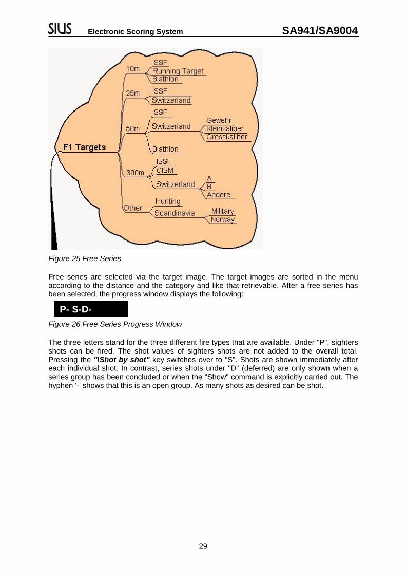
Figure 25 Free Series
Free series are selected via the target image. The target images are sorted in the menuaccording to the distance and the category and like that retrievable. After a free series hasbeen selected, the progress window displays the following:
Figure 26 Free Series Progress Window
The three letters stand for the three different fire types that are available. Under "P", sightersshots can be fired. The shot values of sighters shots are not added to the overall total.Pressing the "\Shot by shot" key switches over to "S". Shots are shown immediately aftereach individual shot. In contrast, series shots under "D" (deferred) are only shown when aseries group has been concluded or when the "Show" command is explicitly carried out. Thehyphen '-' shows that this is an open group. As many shots as desired can be shot.
P- S-D-

Electronic Scoring System SA941/SA9004
30
The following commands can be carried out in a free series:
Command Function“\Match“ The match button on the match unit (RC941) switches from
"Sighters" to "Shot by Shot", from "Shot by Shot" to "Deferred"and back again to "Sighters".
“\Sighters“ Each free series starts with sighters shots. Sighters shots aremarked with "P". The shot values are not added to the overalltotal.
“\Shot by Shot“ A new single shot group can be started using "\Shot by shot".This is also the case if a single group has already been shot.The previous group is summed up and a new group is opened.Thus, a match with 60 shots can be divided up into six groupsof ten for example.
“\Total“(Practice Total)
A practice total sums up all the shots since the last practicetotal or since the start of the program. Therefore, several "Shotby Shot" and/or "Deferred" groups can be added together.Then, shooting can continue. In a position match, the practicetotal can be used as a position total.
“\TOTAL“(Match total)
The match total sums up all the shots of the program and endsthe program that is running. The status window changes to"Stop".
“\Deferred“ A new series group can be started using "\Deferred". If thismeans that a series group in progress will be stopped, this isautomatically flagged up before further shooting can takeplace.
“\Show“ The shots from a series group that have yet to be shown canbe called up from the memory using "\Show". The seriesgroup won’t be finished automatically.
“\Score“ In position matches, a one tenth score is usually used for thefinal. If a secondary score exists for the chosen target image(e.g. one tenth rings), pressing the "\Score" commandreplaces the primary score with that secondary score and thesecondary score drops out. By pressing the "Score" commandagain, this process is reversed. If a shot is fired in one-tenthscore in a program, the total is also given with a decimal point.

Electronic Scoring System SA941/SA9004
31
Command Function“\Other\“Next Primary Score
The primary score can be changed without affecting thesecondary score. There are some target images which havemore than two possible score methods. In Germany forexample, it is customary to operate with a partial score. If a freeseries is selected and so a target image, the most commonscore is selected first. The firer can subsequently select adifferent score.
“\Other\“Next Secondary Score
Just as the primary score can be altered with "\Next PrimaryScore", the secondary score can also be altered using "\NextSecondary Score".
Table 12 Free Series Control Menu Commands
Alterations to the score method during a running program should be avoided.This creates program totals which are calculated from the various scores.
The score methods of a free series must be checked after a recovery processand if necessary corrected.
4.4.3 Fixed Programs
Fixed programs are stored permanently. A fixed program prescribes the order of the shootinggroups. The control unit ensures that the planned order is adhered to. Fixed programs arewidespread in Switzerland particularly. In the first versions of the SIUS scoring systems, onlyfixed programs were available. The options with fixed programs go way beyond thepossibilities of user programs. In a fixed program for example, the exact course of theprogram, the printout and all other settings can be automatically altered, even during thecourse of the program. The classic example is the Swiss federal program which prescribes aprecise print format. This print format cannot be altered by the user.
The progress window during this fixed program looks like this:
Figure 27 Fixed Program Progress Window
An open "P" sighters group permits any number of sighters shots. Afterwards, five single "S"shots need to be shown. The federal program will subsequently change the target imagefrom A5 to B4. On the B4 target, sighters shots may be shot again. Thereafter, five singleshots are shown individually followed by a 2, a 3 and finally a 5 series deferred. The currentlyactive section of the program is shown in inverse font.
P- S5P-S5 D2 D3 D5
Electronic Scoring System SA941/SA9004
32
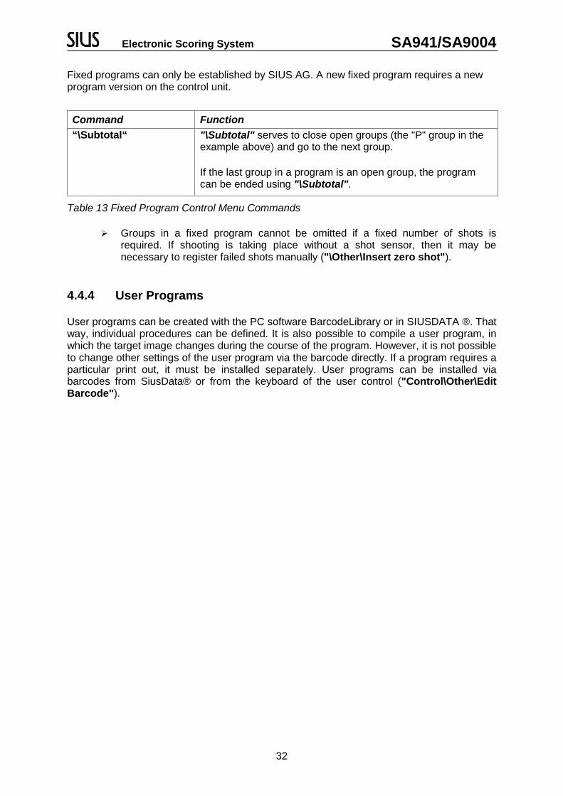
Fixed programs can only be established by SIUS AG. A new fixed program requires a newprogram version on the control unit.
Command Function“\Subtotal“ "\Subtotal" serves to close open groups (the "P" group in the
example above) and go to the next group.
If the last group in a program is an open group, the programcan be ended using "\Subtotal".
Table 13 Fixed Program Control Menu Commands
Groups in a fixed program cannot be omitted if a fixed number of shots isrequired. If shooting is taking place without a shot sensor, then it may benecessary to register failed shots manually ("\Other\Insert zero shot").
4.4.4 User Programs
User programs can be created with the PC software BarcodeLibrary or in SIUSDATA ®. Thatway, individual procedures can be defined. It is also possible to compile a user program, inwhich the target image changes during the course of the program. However, it is not possibleto change other settings of the user program via the barcode directly. If a program requires aparticular print out, it must be installed separately. User programs can be installed viabarcodes from SiusData® or from the keyboard of the user control ("Control\Other\EditBarcode").

Electronic Scoring System SA941/SA9004
33
4.4.5 Match (ISSF)
A match has a certain basic setup. It consists of one or more positions. In each position, asmany sighters shots as desired can be fired before the start of the scoring.
Rifle 3*4050 metre
StandingProne Kneeling Final
P- E10P- E10 E-
Shoot OffE10 E10E10
Figure 28 Match Progress Examples (3*40 Rifle)
The firer can change individually from sighters shots to scored shots. Provided that he hasnot fired any scored shots yet, he can also switch back to sighters shots. The scored shotsare typically divided into groups of ten. In the event of a weapon malfunction or any otherinterruption, the firer has the right to fire sighters shots within the scored shots and tosubsequently continue with the normal program.
Command Function
“\Practice\Prone“ Depending on the structure of the chosen match, one of theexisting positions can be chosen. A match does not necessarilyhave to begin with the first position.“\Practice\Standing“
“\Practice\Kneeling““\Practice\Final“ The final is treated technically as an own position. Typically,
this changes the score to the one-tenth ring.
“\Practice\Sighters“ During an ongoing match, the "Sighters" menu item appears inthe “Practice” directory. During the match, it is possible toswitch to exceptional sighters shots using "Sighters". However,this is only permitted in situations which are foreseen in theISSF rules. After the exceptional sighters shots have beencompleted, the position which was shot last appears. By
choosing this position or pressing the Match key on the remoteunit (RC941) the user returns to the normal program.
Table 14 Match Control Menu Commands

Electronic Scoring System SA941/SA9004
34
4.5 Special Disciplines: 25 meters
All 25-metre disciplines are pistol disciplines. They are characterised by being time-controlledand by being managed with a light signal and time control units (TCU). Malfunctions arehandled according to the detailed ISSF rules. Allowed and non-allowed malfunctions canoccur. Depending on the discipline, after such weapon malfunctions the already shot groupswill be repeated (standard pistols) or subsequently completed (sport pistols). Additionally, therules define how the shots to be assesed have to be selected in case of such malfunctions.In 25-metre disciplines, an additional directory entry "\Control\Malfunction" appears on thecontrol menu.
4.5.1 Centre Fire – and Sport Pistols
For centre fire and sport pistol discipline the following commands have to be used:
Command Function
“\Fill series“ Not in use
“\Insert zero shot Inserts a zero shot if e.g. the target was not hit
“\Allowable“ Writes an entry in the log (event memory) so that the decisionstays traceable.
“\Non-Allowable“ Writes an entry in the log and completes the series with zeroshots (NAM – Non-Allowable Malfunction).
“\Calculate Series“ Not in use
Table 15 Malfunction Center Fire and Sport Pistols

Electronic Scoring System SA941/SA9004
35
4.5.2 Standard and Rapid Fire Pistols
The following commands are to be used for standard and rapid fire pistols:
Command Function“\Fill series“ Must be used if a weapon malfunction occurs on the first shot
of a series. The series is filled up and must subsequently berecorded, with one of the following commands, as to whether itwas an allowable or non-allowable malfunction.
“\Allowable“ Writes an entry in the log and causes the last group to berepeated.
“\Non - Allowable“ Writes an entry in the log (event memory) so that the decisionstays traceable.
“\ Calculate Series“ With "\Calculate Series", a malfunction is closed. The shots inquestion are demarcated and summed up as the series total.
Table 16 Malfunction Standard and Rapid Fire Pistols
In the rapid fire pistol discipline (RFP – Rapid Fire Pistol) , shots are fired from one spot ontofive targets lying close together. The program only needs to be installed on one of the fivecontrol units (Master). The four neighbouring lanes (Slaves) are automatically set for theprogram. The classification into groups of five are effected in the same way. The lanes 1 to 5;6 to 10; 11 to 15 and so on form each a group.
Important Note: During the configuration all lanes have to be set to “Stop”. All entries mustbe served by the master.
4.6 Timer
With version 7.3a a timer has been integrated. If active it is displayed in middle of the titlebar. The following three possibilities are at hand to configure the timer:
Control Unit PC All ISSF-Matches (except 25m-disciplines) incorporate a timer which is activated or
disabled through the setting “Programmed Timer“.

Electronic Scoring System SA941/SA9004
36
4.7 Communication
The various devices (control unit, LON Measurement Electronic System, SCB and PC) areconnected together via a LON field bus. The devices can communicate with each other viathis communications network. The LON Measurement Electronic System transmits the rawdata to the control unit so that the control unit can calculate the value of shot and enter itcorrectly into the current program. This is the most important connection. Withoutcommunication from the control unit to the LON Measurement Electronic System, shootingcannot be recorded. The control unit communicates a failed connection to the LONMeasurement Electronic System with the "OFFLINE" signal.
The control unit communicates in addition to the shots also other information to theScoreboard (SCB) and above all to the PC, so that the data from all lanes can be collatedand evaluated.
To prevent an overload of the network, the network is divided into various segments in largerinstallations with several lanes. The cabling requirements and the installation of routers aredescribed in the installation and maintenance introduction.
In terms of operation, it is important that the devices can be spoken to via an address whichis divided into a subnet address and a node address. The node address is defined by thedevices themselves. All devices belonging to one lane must be set to the same subnetaddress (target number). This happens either via a LNR box (lane number box) and thecorresponding rotary switches or by means of settings and programming such as for thecontrol unit (See "System\Hardware\Control Unit\Subnet" and "System\Hardware-\Target\Connect").
The devices recognise independently whether the partner being spoken to is present or not.Communication with the SCB is attempted. If the SCB does not respond, the communicationchannel is reduced to a minimum. If the SCB is turned on subsequently, it can take a coupleof minutes before it is recognised by the control unit. The content of the SCB will be correctlyincorporated in the following shooting program at the latest.

Electronic Scoring System SA941/SA9004
37
5 Maintenance5.1 Reports5.1.1 Settings
The settings report has been reduced so that only those settings are reported which differfrom the factory settings.
Settings Target/Lane 57:Target Changer:B4 AFilter (Activated):Shoot Type:Free SeriesCardinal:Demo (On)Shot Sensor (Off)Language (English)Subnet (57)LongCard:Shot Number......156944Weapon Number.......0Own Shot............0Cross Shot .........0Missed Shot.........0Demo Shot...........8Invalid Shot........0Manual 0'er.........0Shot Counter Test...0String:Firer Name..........Nation..............Reset Date..........26.1. 13:06
Printout 1 Settings Report
When a control unit is fully set according to the user's wishes, it is useful to print out thesettings report and file it. Thus, a control unit that has been repaired or exchanged forexample can be reset to the desired configuration.
Report from the CU941 with the Subnet address 57
The B4 target image was reprogrammed to shaft “A”(“B” is the standard)
The “Shoot Type” filter has been activated. A freeseries has been selected (The shoot type filter is aninternal filter witch cannot be altered by the user)
The “Language” setting has been set to English.
The firer number and the shot counter are used assettings. They are not saved as customer settingshowever.
The firer name and the “Reset Date” of the shotcounter are used as text settings. They too arenot saved as customer settings.

Electronic Scoring System SA941/SA9004
38
5.1.2 Shot Report
The shot report can be used for settling up. The individual shots are described in detail in theshot report.
Shot Report Target/Lane 57:26.1. 16:50 - 26.1. 17:3112 Own Shot1 Cross Shot2 Missed Shot8 Demo Shot0 Invalid shot1 Manual zero4 Shot counter Test
Printout 2 Shot Report
The problems of cross shots and missed shots are discussed in more detail in Chapter 6.9Shot Sensor and 6.10 Mechanical Shot Counter.
5.1.3 Program Settings
In addition to the normal settings reports, the "\Settings\Program" report can be printed under"\System\Maintenance\Reports\Settings". Various programs can affect different settings.The "\Settings\Program" report lists the active settings for the chosen program. It isparticularly useful in terms of troubleshooting.
Shooting events between 16:50 and 17:31

Electronic Scoring System SA941/SA9004
39
5.2 Log
The internal log saves all the incidents which may be needed for documentation purposesand for possible system restoration after an interruption of the power supply. Each incident isdetailed on two lines at least. In the top line, the time of the incident is given in hundredths ofa second. In the second line, the incident class and a textual description are printed. In caseof shots, the coordinates of the shot position are documented in another line.
The most important details of a log printout are explained below:
Log Report Target/Lane 57 1-26-2004 16:54:05
Version/Release:
Main
Main V7.1e Final
26.6.2004 13:01
HIC=8002 PIC=606 Lon=2.0b
Size 49152:48
Free 47994
13:06:14.12
DiagnosticE Log erased ()
13:06:16.60
DiagnosticE Monitor started ()
13:07:09.05
Program... Start:Target: 57 (1) Targ
13:07:09.54
Practice...Start:
13:07:09.99
Group..... Start:
13:07:08.72
Shot..... 1 B 8 !P
X: -17.65 Y: 4.76
14:51:19.19
Group..... Stop:
14:51:42.26
Shot..... 1 B 10*!
X: -2.31 Y: 2.55
14:51:42.25
Shot..... 2 C 10 !
X: -4.57 Y: -2.70
14:51:43.69
Shot..... 3 L 10 !
X: -7.32 Y: 0.44
14:51:43.87
Shot..... 4 D 9 !
X: 4.05 Y: -11.24
14:51:54.69
Shot..... 5 C 9 !
X: -10.12 Y: -11.05
14:52:03.38
Group..... Stop:Subtotal 48 Subtotal 48
Printout 3 Log Printout
Subnet address of the CU941 andprintout time
Software- and hardware versions ofthe CU941
Amount of memory used by the logand the number of log entries.
Available log memory
Diagnose Eintrag
Program start – produced when thefirst shot in the program is fired
1st shot event in the program
* inner Ten
! Demo Shot
X. / Y: Coordinates in millimetres
Conclusion of the 2rd group
Diagnosis entry
Start of the 2nd group

Electronic Scoring System SA941/SA9004
40
5.3 Target Test
The target test provides software and hardware versions as well as information about theLON Measurement Electronic System which is set to the same target number as the controlunit from which the target test is triggered.
Target Test Target/Lane 57 28.1.2004 13:39HIC=0 TIC=0 PIC=12Light Signal=Not connectedTemperature=27.0 °CVersion/Release 2.0dMix=0Time difference=-60 msRunning target=Disconnected
Printout 4 Target Test
The significance of the various values is explained in the following table:
Variable Value DescriptionHIC Hardware version of the LON Measurement Electronic System
TIC Target Index Code
0 LON Measurement Electronic System without target
1 S10-LON
2 S25/50-LON
3 25-LON
4 S110-LON
5 S310-LON
6 S305-LON (boar 100m target)
7 Deltabar 100-LON
8 Deltabar 128-LON
9 S101-LON
11 SL12-13
12 VS100 (speed measuring stick)
22
23 SL2418
129 LS10
130 HS10
131 HS2550
132 LS10G2

Electronic Scoring System SA941/SA9004
41
Variable Value DescriptionMIX Mounting Index
0 Normal
3 Mounted upside down
5 Back to front
7 Upside down and back to front
Table 17 Target Test Data
The PIC is a hardware version descriptor and "Version\Release" is a software descriptor ofthe LON Measurement Electronic System. The time difference is measured from thatmoment the LON Measurement Electronic System has sent the target test to that time thecontrol unit evaluates the target test. A time difference of less than 100 milliseconds isnormal. Greater differences indicate an incorrect time synchronisation.
5.3.1 New Target Systems HS/LSWith the new targets the target test has been supplemented by the following tasks:
Number of poor sensors: 0
Black/white distance statistics:
Average 179.60
Maximum 223.44
Minimum 147.62
Print out 5 Supplemented Target Test for the New Targets
In case of poor sensors a list names them all. If several adjacent sensors are affected it ispossible that a foreign object is located in the detection field. Thus, the detection is disabled.
The black/white distance statistics shows the measuring dynamics of the detection system:the higher the value the better. Direct sunshine or reflections may deteriorate this value. Avalue of 100 is sufficient for a correct measurement.
The target adjusts itself automatically to alterations of the lighting conditions by dynamicallyperforming different comparisons. Should the target fail in adjusting itself to the givenconditions it sends a message to the control unit. Thus, the status of the control unit changesautomatically to “OFFLINE”. Subsequently, the target restarts and recalibrates. Was thisaction successful the control unit changes to “READY”. As long as the status is “OFFLINE”the target cannot detect any shots.

Electronic Scoring System SA941/SA9004
42
6 Devices6.1 Scoreboard (SCB)
Figure 29 ScoreboardThe scoreboard is suitable as a display for spectators, particularly in larger halls. Someinstallations can display the name, nation and start number of the firer as well as the shotvalues. Normally the last ten shots are displayed along with the group and position totals aswell as the overall total. With System 7, the scoreboards can also be used in free series oruser programs.
That the control unit can operate the scoreboard, the scoreboard must be set to the correcttarget number (subnet address). The target number can be set with the rotary switch at theback of the unit. Only values between 1 and 253 are permitted. The target number is onlytaken over when the SCB is switched on. After a change of address, the SCB must beswitched off and on again.
After an interruption of the power supply to the scoreboard the scoreboard is automaticallysynchronised with the control unit. Older versions of the SCB software cannot synchronise tothe control unit automatically. In that case the control unit has to be restarted after thescoreboard. After it has been switched on, the SCB displays the following three pieces ofinformation on the right hand side:
Number Meaning127 The node address is 127. This is an internal part of the SCB address.
7 The middle number shows the target number set on the SCB by means of arotary switch at the back.
103 The bottom number gives the software version of the SCB.
Table 18 Meaning of the Numbers on the SCB after Switching On
That the scoreboard can be used, the following setting"\System\Hardware\SCB\Active" must be set at the start of a program. If thissetting is turned on during a program, the scoreboard will only be supplied withinformation from the next program onwards.

Electronic Scoring System SA941/SA9004
43
6.2 LON-Measurement Electronic System (LME)
The LON Measurement Electronic System consists of the following components. Thecomponents can be found via the Target Test. ("\System\Maintenance\Self Test\TargetTest").
Component Version ExamplesAltera (FPLA) PIC=12
Hardware HIC=0
Target code TIC=0
LON Software 2.0d
Table 19 LON-Measurement Electronic System Components
The LON Measurement Electronic System must use the same target number (subnetaddress) as the associated control unit. The target number can be programmed from thecontrol unit. This procedure is described in (Chapter 2.2 Connect Target) or in the "Appendixto the System 7 User Manual" under "\System\Hardware\Target\Connect".
Alternatively, targets can be fitted with an LNR Box or a LNR Print. In this case, theprogramming via the control unit is omitted.
6.3 LNR-Box (Lane Number Box)
The LON Measurement Electronic System as well as the control unit can, on certaininstallations, be fitted with LNR Boxes or LNR Prints. A LNR Box or a LNR Print simplifiesaddressing and thus exchanging of devices.The LNR Box and the LNR Print supply the devices with a fixed target number (subnetaddress). Thus, the lane configuration can easily be conducted during the installation and nopower supply is necessary on site.
6.4 New Target Generation (HS10/LS10/HS2550/LS10G2)
The new targets are constructed a bit differently: though they own a LON-software as well itis only used for communication reasons and has not to be downloaded. The application itselfworks in the NIOS processor. The actual version can found via “\System\Maintenance\ SelfTest\Target Test".Component Version ExamplesPIC=0 The new targets don’t own a FPLA Version, so 0
HIC=0 Not applicable either, so 0
Target code TIC=129
NIOS-Software 3.0a
Table 20 Components of the New Target Generation
The target number has to be set via the switches on the target print for all targets of the newgeneration. A configuration via service pin does not work.

Electronic Scoring System SA941/SA9004
44
6.4.1 Target Illumination BG-Light (LS10/HS10/LS10G2)The 10m target is fitted with a target illumination. This illumination can be configured via(“\System\Hardware\Target\Illumination“).The list below shows the different commands:
Befehl Funktion“\On“ Turns the lights on with the chosen intensity.
“\Off“ Turns the lights off.
“\Brighter“ Increases the intensity by 5%
“\Darker“ Decreases the intensity by 5%
“\Set Intensity“ Allows to set the lighting manually to a certain value. This valuecan be between 0 and 100%. The default value of illuminationis 42%.
Table 21 Description of the BG-Light Functions
The HS10 and the LS10G2 save the set values automatically. These values stay the sameafter a re-start. The LS10 however, has no internal memory. Thus, the set values get lostafter a re-start.
6.4.2 Automated Target Elevator ATE10 (LS10/HS10/LS10G2)
If a target is connected with an automated target elevator (10m) this device will be activatedautomatically in accordance with the fix programmed 10m exercises. However, it is alsopossible to command the automated target elevator via the menu. You can find the followingcommands under (“\System\Hardware\Target\Automated Target Elevator“):
Befehl Funktion“\Standing“ Moves the ATE to the position “standing”
“\Prone“ Moves the ATE to the position “prone”
“\Kneeling“ Moves the ATE to the position “kneeling”
“\Up“ Moves the ATE upwards
“\Down“ Moves the ATE downwards
“\Reference Sequence“ Performs a reference sequence. This is executed automaticallyat the start-up and every 10 movements approximately. It canbe triggered manually in case of displacements of the positions(Standing – Prone – Kneeling) during operation.
Table 22 Description of the Automated Target Elevator Functions

Electronic Scoring System SA941/SA9004
45
6.5 Time Control Unit (TCU)
Figure 30 Time Control Unit (TCU)
The Time Control Unit directs the red and green phases of certain sport disciplines. Theproportion between the red and green phases can be individually chosen. The number ofphases can also be set. The red/green signal is directly sent to the LON MeasurementElectronic System. The LON Measurement Electronic System marks its shot reports to thecontrol unit with the corresponding information. The control unit decides on the basis of theprogram whether the shots are valued or not.
The cabling should be handled with care as incorrect wiring can damage thecontrol units!
6.6 Computer (PC)
A customary PC can be connected to the LON network via an "LON Dongle". There areseveral software products available which have been developed for the use with controlunits.
Product Area of UsetBarcode Library Setting user programs. Catalogue of barcodes for the control unit.
SIUSDATA® Collecting shot results from several lanes, controlling andoverseeing a competition and setting user programs.
SIUSRANK® Start and ranking program for international competitions
SIUSLoader ® Software Update Programme for all SIUS devices
SIUSLANE® Control unit software for the use of a detection system.
SIUS 10 LANECOMMAND DESK®
CD10L
Print and display programme
Table 23 PC-Software Overview

Electronic Scoring System SA941/SA9004
46
6.7 Printers (D112)
Print rolls that are perforated in the middle are available for the thermal printer D112. Withthe two column print format, double printouts can be produced directly.
6.7.1 Self Test
An internal self test can be launched by holding down the LF key (Line Feed) while the powersupply is switched on. The quickest way to check the connection from the control unit to the
printer is to press the Help key on the control unit. The telephone numbers for SIUS AG andthe current programme versions are displayed on the printer. It is possible to use bothprinters at the same time
6.7.2 Data Buffer
Each printer stores the data that is yet to be printed in a data buffer. When the printer isswitched on but has been turned "OFFLINE" due to a paper jam or for any other reason, thedata buffer continues to fill with data until it is possible to print again. The data buffer is set tostore approximately 500 lines of text. If the printer is unable to take any texts for a longerperiod of time, data is lost. The data buffer is cleared immediately when the printer isswitched off. This does not affect the entries made in the internal log. Thanks to the internallog, a failed program printout can be created again using the "\System\Reports\Reprint"command.
6.8 Barcode Scanner (BCR Reader)See (Chapter 4.1.2 Barcodes)

Electronic Scoring System SA941/SA9004
47
6.9 Control Unit (CU941, Control Unit, Handheld, ME)
Figure 31 CU941 Control Unit
The control unit (CU941 or FPE06) contains the main data processor for each electronicscoring system. Various software programs exist (System 7, USA versions) which can beloaded onto these devices. The use of the "System 7" version is described in this usermanual. Other software versions are not explained in this manual.
6.9.1 ComponentsComponent Version ExamplesPrint (Print Panel) Rev3
Altera (FPLA) PIC606
Hardware HIC8002
LON Software 2.0b
ME-Software System V7.0i
Bootstrap-Loader 1.0e
Table 24 Control Unit Components
The Bootstrap Loader Software and the Control Unit Software can be loaded with the SIUSLoader® PC Software. The Altera version can be altered by changing an integrated circuitchip. The LON-Software varies depending on the chip set used. That’s why it only can beloaded by SIUS AG.
The above information is printed out on the connected printer by pressing the Help key.
6.9.2 Start-up FunctionsStart-up Option DescriptionCold Start A cold start occurs when the contents of the volatile memory (RAM)
are lost. This happens when the buffer battery can no longer supplysufficient power to the control unit.A cold start can be forced by pressing the reset button at the backof the control unit with a sharp object (with a paperclip for example)when switching on. The reset button is located inside the case. Itcan be reached via the upper of the two small round openings nextto the video socket (This button cannot be reached on the handheldversion because it has a waterproof casing).During a cold start, the settings are reset to the customer settingsand the contents of the log are erased.
Warm Start A warm start is carried out when the contents of the volatile memory(RAM) have not been lost.During a warm start no settings are changed. The control unit willreproduce any unconsumed programs with the "Recovery" function.

Electronic Scoring System SA941/SA9004
48
Table 25 Start-up Options
6.10 Shot Sensor (SAB, C88)
Figure 32 Shot Sensor
The shot sensor for the control unit recognises cross shots (shots from the neighbouring laneonto the own target). The shot sensor informs the control unit when a shot has been firedfrom a weapon. This message opens a time window. Within this time window, a "Shot On"report must be received from the target. If this message is not received, the firer has not hithis own target and receives a shot with the "Missed" comment. If a "Shot On" message isreceived without a "Shot Off" having previously been detected, a neighbouring firer has firedon your lane. Such a shot is known as a "Cross Shot" and is displayed in the target windowwith the cross shot symbol.
The shot sensor is an optional device. It is automatically recognised if it is plugged into thecontrol unit. When it is unplugged, the control unit will work automatically without a shotsensor after a short period of time. A symbol in the target window indicates that a shotsensor is connected. See (Chapter 3.2.1 Display Overview – Target Window).

Electronic Scoring System SA941/SA9004
49
6.11 Mechanical Shot Counter
Figure 33 Mechanical Shot Counter
The mechanical shot counter is designed that the maintenance can be carried out optimally.The mechanical shot counter counts the number of shots fired per target. This enables thewear and tear on the rubber targets to be calculated. As frequent calculations on the numberof fired shots have to be made, the precise functioning of the shot counter is important. Thefollowing table shows which shot incidents are counted and those which are not taken intoconsideration (See "\System\Reports\Shot Counter").
Shot sensor configuration („-“ = Off; „X“ = On)
Shot Off Signal (optional shot sensor on control unit)
Shot On Signal (LON Measurement Electronic System)
Mechanical Shot Counter
Ownshot
Cross Shot
Missed Shot
Remark
- - - - - - - No shot
- - X X X - - Valid shot without shot sensor
- X - -[a] - - - Shot sensor is switched off but reacts nonetheless
- X X X X - - Shot sensor is switched off but reacts nonetheless
X - - - - - - No shot
X - X -[b]
- X - Shot on without shot off cross shot
X X - X X - X Shot off without shot on missed shot
X X X X X - - Valid shot with shot sensor
Signal Effect
Table 26 Shot Occurences and their Effect

Electronic Scoring System SA941/SA9004
50
Neighbouring Targets
If a shot is fired from a target with a shot sensor to a target without a shot sensor, the shot iscounted on both lanes.
Illegal Shot
Whether a shot is marked as illegal has nothing to do with the detection of the shot. A shot isillegal if no exercise has yet been started or when further shooting takes place after acompleted exercise ("STOP", "SHOW", "PAUSE" phases).
Demo Shot
A demo shot is triggered by the Ins key provided the equipment is set to "Demo". Demoshots are requested by the LON Measurement Electronic System (from software version 1.2fonwards, demo shots are already recognised as such by the LON Measurement ElectronicSystem in the communications bundle). Demo shots are counted separately. They do nottrigger a counting impulse on the mechanical shot counter.
[a] When the shot sensor is switched off, a Shot-Off signal does not trigger a countingimpulse (mechanical shot counter). This prevents crosstalk from the shot sensor of a foreigntarget being included in counting.
[b] For possible shot calculations, it is better if the Shot-Off and not the Shot-On are counted.When the shot sensor is working correctly the number of fired shots can be read directly offthe shot counter. The shots can be evaluated even better with the shot report("\System\Reports\Shot Counter"). For maintenance purposes, cross shots are counted ashaving hit the wrong target, in accordance with the above model. The number of cross shotsis small however.
6.12 Remot Control (RC941, RC-ZOOM)
Figure 34 Remote Control (RC941)
The Remote Control RC941 can be connected to the control unit. It is intended for the firer tobe able to give the most important commands without having to leave position. A simpler
version is the RC-ZOOM add-on device. This device has only a Zoom key.
6.12.1 Zoom Key (Enter)
The Zoom key enables the outline of the target to be enlarged, as previously described in thechapter “Usage”.

Electronic Scoring System SA941/SA9004
51
6.12.2 Menu Key
If the "\System\Hardware\RC941\Match Menu" setting is turned on, the Menu key enablesthe "control menu" to be shown as a list window directly on the monitor.
Figure 35 Match-Menü
The Menu and Match keys enable the selection in this window to be moved upwards and
downwards. When the correct command has been selected, the Enter key (Zoom key) can beused to confirm the command. If no action shall take place, the "Cancel" command must becarried out. The menu is immediately faded out if any other occurrence (e.g. a shot or anerror message) takes place.
6.12.3 Match Key
In addition to the navigation functions described above, the Match key has a particular
function during an ISSF position match. Pressing the Match key enables the firer to switchfrom sighters to match individually. He can switch back to sighters provided he has not yetstarted shooting in the match. This function can be carried out via the RC941 (remotecontrol) or via the control unit. After exceptional sighting shots, the firer can return to the
usual program via the Match key. In free series, the Match key can be used to scroll throughthe types of fire.

Electronic Scoring System SA941/SA9004
52
7 Appendix7.1 Separate Document
The menu with the abbreviations which appear on the LCD, as well as the detaileddescription of all barcodes, are to be found in a separate document, the "Appendix to theSystem 7 User Manual".
Content Extract
Menu
Abbreviations
Barcodes with description
Table 27 Contents of “Appendix to the System 7 User Manual““

Electronic Scoring System SA941/SA9004
53
7.2 Frequently Asked Questions (FAQ)
- Why can a particular command or a particular directory not be accessed viathe menu?The use of filters can mask menu areas. Ensure that you have set your filters foryour own requirements.
- How can the installation be checked?In Demo mode, shots can be requested from the LON Measurement ElectronicSystem by means of the Insert key. In this way, communication to the LONMeasurement Electronic System and the functioning of the control unit are largelytested. Demo mode can be turned on and off under"\System\Settings\Other\Demo". The current setting is shown in the statuswindow.
- The control unit remains on "OFFLINE" and shots are not shown in theprogram that is switched on. What is to do?The control unit cannot communicate with the LON Measurement ElectronicSystem. Check the power supply to the LON Measurement Electronic Systemand the target number configuration. Check the wiring and reconnect the LONMeasurement Electronic System (Chapter 2.2 Connect Target) if necessary.
- The control unit always starts up in English.The settings, including language selection, are saved even when the powersupply is interrupted. They are only lost if the buffer battery is insufficient. Thecontrol unit shows this in the list window after the start-up process and reportsduring the start-up process by three beeps. Check the buffer battery and replaceit if necessary. Save your settings as customer settings.
- How can commanded shooting be controlled from one shooting stand?The control units can be remotely controlled with the SIUSDATA® PC software.All connected control units can be controlled and configured using this software.


Electronic Scoring System SA941/SA9004
55
Item DescriptionSubnet Address The subnet address of all components on one line
(lane, "target") must all be set to the same subnetaddress so that the devices can communicate witheach other. The subnet addresses are usually thesame as the target numbers.
User Program A user program is a shooting program which can onlybe installed using a barcode scanner. With theproducts “Barcode Library” and “SiusData®”,individual user programs can be installed and printedout. The target image and the program progress canbe set with a user program.
Table 28 Short Explanations

Electronic Scoring System SA941/SA9004
56
Index of IllustrationsFigure 1 Example Devices..................................................................................................... 6Figure 2 Minimal Cabling....................................................................................................... 7Figure 3 Screen Display after First Startup............................................................................ 8Figure 4 Connect Target Function ......................................................................................... 9Figure 5 Connect Target........................................................................................................ 9Figure 6 LON Measurement Electronic System with Service PIN .........................................10Figure 7 Target Connected...................................................................................................10Figure 8 Screen Layout ........................................................................................................14Figure 9 Target Image..........................................................................................................15Figure 10 Shot Sensor Symbol and Cross Shot Symbol.......................................................16Figure 11 Shot Window ........................................................................................................16Figure 12 List Window..........................................................................................................17Figure 13 Practice Progress Window....................................................................................18Figure 14 Statistic Window ...................................................................................................18Figure 15 Selection Window.................................................................................................19Figure 16 Status Window .....................................................................................................19Figure 17 Titel Bar................................................................................................................20Figure 18 Funktion Key Bar..................................................................................................20Figure 19 Menu Navigation ..................................................................................................22Figure 20 Barcode Scanner..................................................................................................24Figure 21 Settings Management...........................................................................................25Figure 22 Filter Settings Path ...............................................................................................26Figure 23 Unfiltered Menu ....................................................................................................27Figure 24 Filtered Menu .......................................................................................................27Figure 25 Free Series...........................................................................................................29Figure 26 Free Series Progress Window ..............................................................................29Figure 27 Fixed Program Progress Window .........................................................................31Figure 28 Match Progress Examples (3*40 Rifle) .................................................................33Figure 29 Scoreboard...........................................................................................................42Figure 30 Time Control Unit (TCU).......................................................................................45Figure 31 CU941 Control Unit ..............................................................................................47Figure 32 Shot Sensor..........................................................................................................48Figure 33 Mechanical Shot Counter .....................................................................................49Figure 34 Remote Control (RC941) ......................................................................................50Figure 35 Match-Menü .........................................................................................................51
Index of PrintoutsPrintout 1 Settings Report ....................................................................................................37Printout 2 Shot Report ..........................................................................................................38Printout 3 Log Printout..........................................................................................................39Printout 4 Target Test...........................................................................................................40Print out 5 Supplemented Target Test for the New Targets ..................................................41

Electronic Scoring System SA941/SA9004
57
Index of TablesTable 1 Sius AG Addresses .................................................................................................. 4Table 2 Typographics Conventions ....................................................................................... 5Table 3 Minimal Cabling (Connections) ................................................................................. 7Table 4 Barcodes set subnet on control unit.........................................................................11Table 5 Program Examples ..................................................................................................13Table 6 Shot Attributes.........................................................................................................18Table 7 Status Overview ......................................................................................................19Table 8 Status Overview 2 ...................................................................................................20Table 9 Keyboard Functions.................................................................................................23Table 10 Program Types ......................................................................................................28Table 11 General Control Menu Commands ........................................................................28Table 12 Free Series Control Menu Commands...................................................................31Table 13 Fixed Program Control Menu Commands..............................................................32Table 14 Match Control Menu Commands ...........................................................................33Table 15 Malfunction Center Fire and Sport Pistols..............................................................34Table 16 Malfunction Standard and Rapid Fire Pistols .........................................................35Table 17 Target Test Data....................................................................................................41Table 18 Meaning of the Numbers on the SCB after Switching On.......................................42Table 19 LON-Measurement Electronic System Components..............................................43Table 20 Components of the New Target Generation...........................................................43Table 21 Description of the BG-Light Functions ...................................................................44Table 22 Description of the Automated Target Elevator Functions .......................................44Table 23 PC-Software Overview ..........................................................................................45Table 24 Control Unit Components ......................................................................................47Table 22 Start-up Options ....................................................................................................48Table 26 Shot Occurences and their Effect ..........................................................................49Table 24 Contents of “Appendix to the System 7 User Manual““ ..........................................52Table 28 Short Explanations ................................................................................................55

Electronic Scoring System SA941/SA9004
58
Index of Key Terms
AAppendix ............................................... 52
BBarcode- Library.................................... 45Barcodes............................................... 24Brightness Control................................... 7
CCategory ............................................... 27Center Fire Pistol................................... 34Center Score ......................................... 15Centre fire ............................................. 34Cold Start .............................................. 47Communication ..................................... 36Communicaton Cable.............................. 7Connect................................................... 8Contact.................................................... 4Control Menu......................................... 28Conventions ............................................ 5Coordinates........................................... 17Cross Shot ...................................... 16, 49Customer Settings................................. 25
DDeferred ................................................ 30DEMO ................................................... 20Demo Shot ...................................... 17, 50Devices ................................................... 6Display Overview................................... 14Distance ................................................ 27
EEnter ..................................................... 23Escape .................................................. 22
FFactory Settings .................................... 25Filters .................................................... 26Firer Number ......................................... 19Fixed Program....................................... 31Flag....................................................... 17Frame-Hit .............................................. 17Free Series............................................ 28Function Key ......................................... 22Functions Group.................................... 27Funktion Key Bar................................... 20
HHelp....................................................... 23
Home.................................................... 22
IIllegal Shot........................................... 50Inner-Ten .............................................. 17Insert..................................................... 23
KKeyboard .............................................. 21
LLanguage.............................................. 12Layout................................................... 14List Window .......................................... 17LNR Box ............................................... 43Log ....................................................... 39LON ...................................................... 43LONORG® ........................................... 45
MMaintenance ......................................... 37Malfunction ........................................... 34Manual.................................................... 4Master................................................... 35Match.................................................... 33Match Key............................................. 51Mean Point of Impact .......................16, 18Measurement Electronic ....................... 43Menu Key ............................................. 51Missed Shot .......................................... 49Move Down........................................... 23Move Up ............................................... 23MPI ....................................................... 18
NNew Target Generation
(HS10/LS10/HS2550/LS10G2).......... 43Next Primary Score............................... 31Next Secondary Score .......................... 31Next Window......................................... 23
OOFFLINE .............................................. 19Olympic Rapid Fire ............................... 35Option ................................................... 23Own Shot .............................................. 49
PPAUSE ................................................. 19Position................................................. 33Power Supply.......................................... 7

Electronic Scoring System SA941/SA9004
59
Power switch ........................................... 7Printers.................................................. 46Progress Window .................................. 18
RRapid fire pistol ..................................... 35RC941................................................... 50RC-Zoom............................................... 50READY.................................................. 19RECOVERY.......................................... 19Remote Control ..................................... 50Repeat .................................................. 28RFP....................................................... 35
SSAB....................................................... 48Score method........................................ 15Scoreboard............................................ 42Selection Window.................................. 19Service-Pin............................................ 10Set Discipline ........................................ 13Settings ........................................... 25, 37Short Explanations ................................ 54Shot by Shot.......................................... 30Shot counter.......................................... 49Shot Number ......................................... 16Shot Report ........................................... 38Shot Sensor .......................................... 48Shot Window......................................... 16SHOW................................................... 19Sighters Shot......................................... 17Sighters triangle .................................... 15SIUS 10 LANE COMMAND DESK®....... 45SIUSDATA®.......................................... 45SIUSLANE®.......................................... 45SIUSRANK® ......................................... 45Slave ..................................................... 35
Sport pistole.......................................... 34Starting up .............................................. 8Statistics Window.................................. 18Status Window...................................... 19STOP.................................................... 19Subnet Address .................................... 11Subtotal ................................................ 32Synchronised ...................................13, 19
TTarget Catalogue .................................. 13Target Name......................................... 15Target Number...................................... 20Target Test ......................................40, 43Target Window...................................... 15TCU ...................................................... 45Time Control Unit .................................. 45Timer .................................................... 35Total...................................................... 30TOTAL.................................................. 30
UUser Group ........................................... 27User Program ....................................... 32
VVersion ................................................. 39Video Cable ............................................ 7
WWarm Start............................................ 47Weapon Type ....................................... 27
ZZoom ...............................................16, 50