system # v900068 · system #v900068 international 2001 - 2003 4300, 4400 series dt466 underhood air...
TRANSCRIPT

System # V900068
INTERNATIONAL 2001 - 20034300, 4400 SERIES DT466

Document #1930036
2
Installation Manual � Document Number: 1930036
VR70 Underhood Air CompressorSystem Number V900068
Application:INTERNATIONAL 2001 - 2003, 4300, 4400 SERIES DT466(Trucks with air brakes will require an adaptor kit.)
Publication Date:Revised by S.Coker, 20th November 2003.
Registered Trademarks:VR70, VMAC and Throttle Commander are registered trademarks of VMAC.
International is a registered trademarks of Navistar International Corporation.
Loctite, Klean N� Prime, 242 and PST are registered trademarks of Loctite Corporation.
Nylok is a registered trademark of Nylok Fastener Corporation.
Notice:Manuals and products are subject to change without notice.
Copyright 2003The contents of this manual may not be reproduced in any form without the express written permission of
VMAC
Printed in Canada

Document #1930036
3
CONTENTS
GENERAL INFORMATION .................................................................................................... 5INTRODUCTION ................................................................................................................. 7TERMS & SYMBOLS.......................................................................................................... 7INSTALLATION NOTES ......................................................................................................... 8TORQUE SPECIFICATIONS .................................................................................................. 8SYSTEM IDENTIFICATION NUMBER PLATE .............................................................................. 9WARRANTY ................................................................................................................... 10ORDERING PARTS ........................................................................................................... 10TOOL REQUIREMENTS ..................................................................................................... 10SPECIAL NOTES............................................................................................................. 11
PART 1: PREPARING FOR INSTALLATION ................................................................. 131.1 PREPARATION FOR INSTALLATION ....................................................................................... 15
PART 2: INSTALLING THE OIL/AIR SEPARATOR TANK AND LINES ........................ 172.1 INSTALLING THE OIL/AIR SEPARATOR TANK BRACKETS ......................................................... 192.2 ALTERNATE OIL/AIR SEPARATOR TANK MOUNTING LOCATIONS .............................................. 202.3 INSTALLING THE C-CLAMPS .............................................................................................. 202.4 ATTACHING THE LINES TO THE OIL/AIR SEPARATOR TANK ..................................................... 22
PART 3: INSTALLING THE COMPRESSOR AND OIL COOLER ................................. 233.1 INSTALLING THE VR70 CRANK PULLEY ............................................................................. 253.2 OIL COOLER INSTALLATION .............................................................................................. 263.3 INSTALLING THE MAIN BRACKET ........................................................................................ 283.4 INSTALLING THE MAIN BRACKET BRACE ............................................................................. 303.5 INSTALLING THE COMPRESSOR ......................................................................................... 303.6 ATTACHING THE LINES TO THE COMPRESSOR ...................................................................... 313.7 INSTALLING THE ALTERNATOR AND OEM BELT .................................................................... 323.8 INSTALLING THE MAIN BRACKET FRONT PLATE & VR70 BELT .............................................. 333.9 ADDING OIL TO THE SYSTEM ........................................................................................... 353.10 COMPLETING THE INSTALLATION ........................................................................................ 36
PART 4: INSTALLING THE CONTROL COMPONENTS ............................................... 374.1 INSTALLING THE CONTROL UNIT ........................................................................................ 394.2 CONNECTING THE WIRING ............................................................................................... 414.3 INSTALLING THE THROTTLE ............................................................................................... 434.4 HYDRAULIC BRAKES ....................................................................................................... 43
4.4.1 HYDRAULIC BRAKES AND STANDARD TRANSMISSION ............................................... 444.4.2 HYDRAULIC BRAKES AND AUTOMATIC TRANSMISSION .............................................. 44
4.5 FINAL TESTING & ASSEMBLY ............................................................................................ 45APPENDIX A � GENERIC SOLDERING ................................................................................. 47
PART 5: ILLUSTRATED PARTS LIST ........................................................................... 49
WARRANTY REGISTRATION

4
Document #1930036

SYSTEM #V900068
INTERNATIONAL 2001 - 20034300, 4400 SERIES DT466
UNDERHOOD AIR COMPRESSOR
TM
GENERAL INFORMATION

Document #1930036
6

Document #1930036
7
Introduction
This book provides installation instructions for the VMAC underhood air compressor installationkit.
This symbol indicates that there is a possibility of personalinjury if the indicated warning is not followed.
This symbol indicates that there is a possibility of damage to theequipment if the indicated warning is not followed.
This symbol indicates that there is additional information orspecial emphasis on a specific procedure.
Terms and SymbolsThis manual uses the following terms and symbols:
� DDC - Drive Disable Circuit� ft-lbs - Foot Pounds (torque)� HHCS - Hex Head Bolt (also called a hex bolt)� N�m - Newton Meters (metric torque)� OEM - Original Equipment Manufacturer� SHCS - Socket Head Bolt (also called an allen head bolt)� Hex - Hexagon (six sided)

Document #1930036
8
Installation Notes
It is important that you complete all the installation steps before operating the system.
Follow all safety precautions for underhood mechanical work.
Use Loctite 242 or equivalent on all engine-mounted fasteners.
All hoses, tubes and wires which are rerouted or shifted during installation must be secured so thatthey do not contact excessively hot areas or sharp edges. Where possible, follow the routingsuggestions in this manual.
These installation instructions are intended as a general guide. In some instances, due to variationsin vehicle manufacture or if prior modifications have been made to the vehicle, it may be necessaryto carry out grinding, bending or rearranging operations for correct fit. These operations mustfollow sound, standard shop practices.
Left and right definitions in this manual are determined when sitting in the driver�s seat, facingforward.
All fasteners must be of the correct size and torqued according to specifications (Table 1). Torquespecifications are in foot pounds (ft-lb) and are only applicable when Loctite is used. If the threadsare dry, add 20% to the torque values.
Torque Specifications
STANDARD GRADE 8 NATIONAL COARSE THREAD
Size 1/4 5/16 3/8 7/16 1/2 9/16 5/8 3/4
Foot-pounds 9 18 35 55 80 110 170 280
Newton meter 12 24 47 74 108 149 230 379
STANDARD GRADE 8 NATIONAL FINE THREAD
Size 3/8 7/16 1/2 5/8 3/4
Foot-pounds 40 60 90 180 320
Newton meter 54 81 122 244 434
METRIC CLASS 10.9
Size M8 M10 M12 M14 M16
Foot-pounds 19 41 69 104 174
Newton meter 25 55 93 141 236
Table 1 � The fastener values are applicable when Loctite is applied unless otherwise specified.
Table 1 Torque Specifications

Document #1930036
9
Hose Diameter Color Coded Label
1/4 inch Yellow5/16 inch Orange1/2 inch Blue5/8 inch Blue3/4 inch Green1 inch Green
1-1/4 inch Green
Table 2 Hose color codesTable 2 above illustrates the color code used by VMAC to define the different hose diameters.
Check that system hoses are all tight before running the system. Refer to setup procedure in theOwner�s Manual before attempting to run this air system.
Different frame designations will affect the tank mounting position. You may have to move thetank rearward from the standard position on your application. If you must move the tank, the linesmay be too short. If this is the case, measure the hose shortfall and order a �Hose Extender Kit�,P/N (A410XXX). The last three digits in the P/N indicate the length of the extension, for example,A410055 is a 55 inch hose extender kit. You would receive a kit which includes a set of each sizehose 55 inches long required to relocate the tank.
System Identification Number Plate
The System Identification Number Plate included with the kit must be attached to the vehicle at thetime of installation. Locate the plate as shown below. Mark and drill two holes using a 7/64 inchdrill bit. Secure the plate in position using the supplied #6 pan head, self-tapping screws.
This plate provides information, which allows Vmac to assist in customerinquiries and the ordering of parts. It is important that this plate is affixed tothe vehicle.
Figure 1 Identification plate mounted

Document #1930036
10
Warranty
The VMAC warranty form is located at the back of this manual. This warranty form must becompleted and mailed or faxed to VMAC at the time of installation for any subsequent warrantyclaim to be considered valid.
Ordering Parts
To order parts, contact your nearest VMAC dealer.
Please quote the VMAC part number, the description and the quantity.
Tool Requirements
The following tools are required for installation:
* 1/2 inch drive metric socket set* 8 to 24 mm metric wrench set* 1/2 inch drive SAE socket set* 7/16 inch to 7/8 inch SAE wrench set* Allen key sets - metric & SAE* mechanic�s screwdriver set* nut drivers - 5/16 to 3/8 inch* 1/2 inch drill with assorted bits up to 1/2 inch* hacksaw or zip wheel suitable for cutting metal* OEM fan wrench tool
The following tools are required for throttle component installation:
* small solder gun or soldering pen* wire cutters* wire strippers* crimping tool* digital multimeter, preferably with a frequency (Hz) setting* small jeweller�s screwdriver set for adjustment of the throttle control

Document #1930036
11
Special Installation Notes
If you intend to use an auxiliary air tank with this system you must observe thefollowing installation procedure. Failure to observe this procedure will resultin damage to the system.
1. The line from the VR70 tank to the auxiliary air tank must have a check valve installed toprevent blow-back from the auxiliary tank and to prevent moisture from entering the VR70tank.
2. The line to the auxiliary tank must not be installed in the bottom of the tank, but must beinstalled as high as possible to prevent water from clogging the line.
Figure 3 Auxiliary air tank piping

12
Document #1930036

SYSTEM #V900068
INTERNATIONAL 2001 - 20034300, 4400 SERIES DT466
UNDERHOOD AIR COMPRESSOR
TM
PART 1
PREPARING FORINSTALLATION

Document #1930036
14

Document #1930036
15
1.1 Preparing for Installation
1. Disconnect the batteries
2. Drain the coolant
3. Remove the four OEM bolts used to secure the passenger side fender shroud and set the shroudaside temporarily.
4. Disconnect the radiator end of the passenger side turbo/intercooler pipe and allow it to hangloose.
5. Remove the air cleaner to turbo rubber intake duct.
6. Remove the air cleaner
7. Remove the fan. Be sure to use the factory recommended fan-removing tool.
8. Lay the fan down temporarily in the fan shroud and carefully lean it against the radiator withcardboard protection between.
9. Remove the OEM eight-rib drive belt by releasing the OEM tensioner and allow the belt tohang loose.
10. Remove the alternator.
11. Remove the OEM eight-rib drive belt tensioner.
12. Unplug the cam sensor wiring and remove the bolt that secures the cam sensor and set it asidetemporarily. Rotate the cam sensor clockwise to expose the M8 bolt hole underneath.
13. Remove the three M10 bolts locating the alternator-mounting bracket and remove the M8 boltthrough the timing cover and alternator bracket. Discard the alternator bracket.
14. Remove the plastic OEM heater hose clamp and bracket from the front right of the cylinderhead. Discard the plastic clamp but retain the mounting nut, bolt and bracket. Put the originalbracket-mounting bolt back into the hole and retighten it to secure it in place.
15. Remove the two OEM bolts locating the engine-lifting lug on the side of the cylinder head andremove and discard the lifting lug. It will be necessary to zip wheel the head of the bolt afterloosening to be able to remove it.

16
Document #1930036

SYSTEM #V900068
INTERNATIONAL 2001 - 20034300, 4400 SERIES DT466
UNDERHOOD AIR COMPRESSOR
TM
PART 2
INSTALLING THE OIL/AIRSEPARATOR TANK AND
LINES

Document #1930036
18

Document #1930036
19
2.1 Installing the oil/air separator tank brackets
1. Measure 10-1/2 inches (26 cm) back from the rear of the front spring hanger and mark thelower edge of the driver side frame rail (Figure 2.1).
Figure 2.1 Bracket mounting -driver side Figure 2.2 Bracket tab facing the frame rail
2. Measure 23 inches (58 cm) back along the rail from the previous mark and mark the loweredge of the driver side frame rail (Figure 2.1).
3. Pass the threaded end of the supplied tank cable strap, through the top hole in the front tankmount bracket from the flat side of the bracket. Pull the cable right through to the stop(Figure 2.2).
4. Hang the front tank mount bracket on the inside of the driver side frame rail at the 10-1/2 inchmark, with the cable over the top of the frame rail. Wrap the cable around the outside of theframe rail and pass the threaded end back through the hole in the tank mount bracket thataligns with the under side of the frame rail. Set the notch protruding from the bracket on theinside of the frame, locating the bracket on the top edge of the lower frame rail lip.
5. Repeat the above procedure with the rear tank mount bracket and set this bracket at the rearmarked position on the frame rail.
6. Square up the brackets and install the two 5/16 inch thick washers then the two 5/16 inch nutsto the threaded ends of the tank cable straps. Tighten the nuts on the cables until the tankmounting brackets are securely located. Do not over tighten the cables.

Document #1930036
20
2.2 Alternate oil/air separator tank mounting locations
The 2.2 section is for trucks with under deck exhaust system or trucks thatcannot mount the oil/air separator tank on the driver side of the vehicle.
1. Measure 20 inches (51 cm) back from the front spring hanger along the frame rail and markthis as the position of the first bracket (Figure 2.3).
2. Measure an additional 20 inches (51 cm) back from the first mark to make a second markingfor the rear tank-mounting bracket.
3. Following these measurements, install the tank brackets in the marked positions as outlined infigure 2.4 and steps 3, 4, 5, and 6 of section 2.1.
Figure 2.3 Bracket mounting, passenger side Figure 2.4 Tank brackets, passenger side
2.3 Installing the C-clamps
The C-clamps will need to be on the opposite side of the tank when installingthe tank on the passenger�s side.
1. During the installation, it will help to align the clamps if the tank is set on the edge of aworkbench (Figure 2.5). Remove the 1/4 × 3-1/2 inch pinch bolts and nuts from both thesupplied tank mount C-clamps. Slide both clamps over the front of the tank with the flat sideof the clamp facing the opposite side to the oil filter. Set the front clamp at 6 inches from thefront of the tank. (For a driver side tank mount) set the rear clamp position 23 inches (58cm) back from the front bracket. (For a passenger side tank mount) set the rear clampposition 20 inches (51 cm) back from the front bracket). Set the clamps so that the up arrowon the front of the tank is in the vertical position and check that the clamp holes align with themount bracket holes. Reinstall the 1/4 × 3-1/2 clamp pinch bolts and nuts and tighten enoughjust to loosely hold the tank.

Document #1930036
21
2. Insert the threaded end of the 5/16 inch scavenge tube into the fitting at the bottom rear of thetank (Figure 2.6). Route the steel tube section down the upper inside (frame rail side) of thetank.
3. Insert the threaded end of the 1/4 inch pressure control tube into the fitting at the top rear of thetank (Figure 2.6). Route the steel tube section down the upper inside (frame rail side) of thetank alongside of the scavenge tube.
4. Lift the tank into position on the inside of the driver side frame rail and support it in position.Install two of the supplied 5/16 × 1 inch tank mount bolts with 5/16 inch flat washers to fastenthe lower tank mount clamps to the bottom holes in the frame mount brackets. Install the 5/16Nylok nuts with flat washer and tighten hand tight. Ensure there is adequate clearance for thetank and other vehicle components.
5. Back off the front C-clamp 1/4 × 3-1/2 inch clamp pinch bolt and slide the U-shaped bracketthat is used to mount the P-clip, under the front C-clamp with the vertical section of thebracket facing backward. Open the small insulated P-clip and fit it over the two steel tubes ofthe scavenge and pressure control lines. Using the supplied fastening nut and bolt, secure theclip around the two lines and tighten the nut and bolt to specification (Figure 2.7).
Figure 2.7 Tubes secured with P-clip
Figure 2.5 C-clamp mounting positions Figure 2.6 Rear view of lines

22
Document #1930036
6. Rotate the U-shape bracket to allow the steel tubes to run straight and aligned with the tank.Tighten both C-clamps.
7. Insert the two remaining 5/16 × 1 inch tank mount bolts through the upper holes in the tankmount C-clamps to secure the tank to the tank mount brackets. Install the last two 5/16 inchflat washers and Nylok nuts. Rotate the tank so the arrow on the front of the tank is vertical.
8. Reinstall and tighten the 1/4 × 3-1/2 inch pinch bolts on the C-clamps and fully tighten all four5/16 inch tank mount bolts and nuts to specification.
If the tank is not set in the correct vertical position (arrow on the rearblowdown cap pointing straight up) the oil scavenge line will not workcorrectly.
2.4 Attaching the lines to the oil/air separator tank
1. Normal Driver�s Side Tank Mounting: Connect the straight connector of the 1/2 × 48 inchlong oil return hose directly to the front of the tank.
2. Feed the ends of the 1/4 and 5/16 inch hoses up into the engine compartment.
3. Install the straight connector of the 3/4 inch main air discharge hose to the top fitting on thefront of the tank (Figure 2.8). Route the hose up into the engine compartment with the 1/4 and5/16 inch hoses.
Figure 2.8 Front view, (oil filter removed)
4. Alternate Passenger Side Tank Mounting: Connect the female end of the 1/2 inch extensionhose to the 1/2 inch fitting on the lower front of the tank and tighten securely.
5. Alternate Passenger Side Tank Mounting: Connect the straight end connector of the 1/2 inch48 inch long hose to the male connector on the end of the 1/2 inch extension hose fitted to thetank. Tighten securely using two wrenches.

SYSTEM #V900068
INTERNATIONAL 2001 - 20034300, 4400 SERIES DT466
UNDERHOOD AIR COMPRESSOR
TM
PART 3
INSTALLING THECOMPRESSOR AND OIL
COOLER

Document #1930036
24

Document #1930036
25
3.1 Installing the VR70 Crank Pulley
1. Ensure that the face of the OEM pulley is clean of all dirt and debris to allow for a good fit ofthe VR70 crank pulley. Align the bolt holes and ensure that the pulley is sitting flat. Afterapplying Loctite to the threads, install the six supplied M10 × 45mm bolts with washers tosecure the pulley and torque to specification (Figure 3.1 and 3.2).
2. Thread the fan spacer onto the front of the fan pulley. Reinstall the fan and tighten the fan nutto specifications.
Figure 3.1 Bolts in the OEM crank pulley Figure 3.2 VR70 crank pulley installed

Document #1930036
26
3.2 Oil Cooler installation
fastener pack (cooler) (hose)
Figure 3.3
1. Install the VMAC diverter tube as detailed in figure 3.3, cutting the OEM lower radiator hoseapproximately 1 inch (25mm) away from the OEM clamp. Secure the diverter and hose usingthe supplied HS-40 hose clamp.
Some truck configurations may vary in which case the most suitablelocation for the diverter will be approximately 4.0� away from theradiator discharge connection.
2. Apply pipe sealant to the supplied straight 3/4 to 1 inch hose barb and install it into the topconnection in the back of the water pump housing.
The top connection will either be plugged or have the OEM heater return hoseinstalled. In both instances the existing connection or plug should beremoved and the supplied 3/4 to 1 inch hose barb installed as detailed instep 2.
If the connection is occupied by the heater return hose this hose will need tobe relocated as detailed in step 6 and figure 3.3
OEM lowerradiator hose
1 inch hoseVR cooler return
(supplied)1 inch hose
VR cooler feed(supplied)
VMAC diverter tube(supplied)
1 inch
OEM clamp
OEM lowerradiator hose
OEM 90°fitting
3/4 inch hoseto 3/4 NPT connector
below thermostat housing
Upper 1 inchspigot
Lower 1 inchspigot
1 inch hose barbto 3/4 inch NPT fitting
(supplied)
Cut OEM lowerradiator hoseapprox. 1 inch from clamp
Water pump housing
OEM 3/4 inchheater return hose

Document #1930036
27
3. Install the oil cooler with the three supplied M16 × 30mm bolts with flat washers in the engineblock just behind the straight fitting on the water pump housing (Figure 3.4).
Figure 3.4 Cooler mounting locations
4. Cut a suitable length of the 1 inch hose and route it from the straight fitting in the back of thewater pump housing (Figure 3.5) to the bottom spigot of the oil cooler.
5. Cut a 3 inch (8 cm) length of 1 inch heater hose and install it onto the top spigot of the oilcooler and clamp it in place with a supplied HS-16 hose clamp (Figure 3.3). Place an HS-16hose clamp over the hose and install the 1 inch connection of the 1 × 1 × 3/4 inch hose-T intothe hose and clamp it.
6. Cut a suitable length of the supplied 3/4 heater hose and route from the 3/4 NPT connectionfitting below the thermostat housing .(Figure 3.6) to the branch 3/4 inch connection of thehose-T installed in step 5 and secure using an HS10 hose clamp.
7. Cut a suitable length of 1 inch heater hose and route it from the primary coolant flow diverter(installed in step 1) to the remaining connection of the 1 × 1 × 3/4 inch hose-T. Secure thehose in place using the supplied HS-16 hose clamps (Figure 3.3).
Figure 3.5 Cooler mounting locations
Water pumpstraight fitting

Document #1930036
28
8. Relocate the heater return hose connection (if it was connected to the back of the water pumphousing) onto the 3/4 connection of the 1 × 1 × 3/4 inch hose-T, which has to be connected
9. Ensure all connections are tight and all hoses are clear of moving components.
3.3 Installing the main bracket
1. After removing the main bracket from its shipping container, remove the VR belt tensioner andidlers then remove the five bolts securing the VR70 front idler plate to the VR70 main bracket.
It is recommended to remove the VR70 tensioner before mounting the frontplate assembly to allow for easier access to the mounting bolts for propertightening.
2. Clean all dirt and debris from the rear of the timing cover before installing the main bracket.
into the coolant expansion supply hose (Figure 3.3). Secure the hose and Tee in place using thesupplied HS-10 and HS16 hose clamps. Extend as necessary using the supplied connector and3/4 hose.
Figure 3.7 Bolt mounting locations Figure 3.8 Moving the cam sensor bracket
Figure 3.6

Document #1930036
29
3. Fit the VR70 main bracket on the right side rear edge of the engine timing cover with thecompressor mounting plate facing forward (Figure 3.9).
Figure 3.9 Main bracket bolt mounting locations
Item Number Description of fasteners used1 One M10 × 70 hex head bolt, Two 3/8 inch flat washers, One M10 Nylok nut2 One M8 × 60 socket head bolt, Two 5/16 inch flat washers, One M8 Nylok nut3 One M10 × 70 hex head bolt, Two 3/8 inch flat washers, One M10 Nylok nut4 One M10 × 60 hex head bolt, Two 3/8 inch flat washers, One M10 Nylok nut
4. Attach the main VR70 bracket with the supplied two M10 × 70mm, one M10 × 60mm, and oneM8 × 60mm hex head bolts (Figure 3.9 & Table above). Slide one of the supplied 3/8 inch flatwashers on each of the M10 hex head bolts before inserting them into the appropriate holes atthe front of the engine timing cover. Install an additional 3/8 washer on each M10 hex headbolt where it protrudes through the VR70 bracket at the rear before installing the suppliedNylok nuts.
5. Likewise, when installing the one M8 × 60mm socket head bolt near the cam sensor, be sure toslide one of the supplied 5/16 inch flat washers over the socket head bolt before inserting itinto the hole at the front of the engine timing cover. Install an addition 5/16 inch flat washerover this M8 socket head bolt where it protrudes through the VR70 bracket at the rear beforeinstalling the supplied Nylok nut.

Document #1930036
30
3.4 Installing the main bracket brace
1. Locate the hole that was created earlier by removal of the engine-lifting lug. This hole will beused to install the socket head bolt that mounts the main bracket brace to the engine cylinderhead (Figure 3.10).
2. Slide a 7/16 inch washer over the supplied M12 × 30mm socket head bolt. Insert the sockethead bolt with 7/16 inch washer through the rear hole in the main bracket brace and into thehole in the engine cylinder head as described in step 1 (Figure 3.10). Screw into the enginecylinder head but leave a bit of slack to allow for lining up with the two horizontal holes at therear of the compressor plate on the main bracket assembly.
3. Line up the two holes at the rear of the main bracket with the two mounting holes at the frontof the main bracket brace. Insert the two supplied M8 × 35mm hex head bolts that will attachthe bracket brace with the main bracket and screw the 8mm double serrated nuts in place.Tighten the socket head bolt in the engine cylinder head and the hex head bolts with serratedlock nuts to specification (Figure 3.11).
3.5 Installing the compressor
1. Remove the three socket head bolts that secure the VR70 compressor belt guard to the top ofthe compressor and set the belt guard aside temporarily. Reinstall these screws to help securethe inlet control valve during further steps in the installation.
2. Remove the packaging from under the VR70 compressor and retain the captive serrated washernuts. Take extra care to protect the temperature probe wires during installation.
3. Lift the compressor into place on the horizontal mounting plate at the top of the VR70 mainbracket. Line up the studs on the bottom of the compressor with the three holes in themounting plate and thread the supplied captive serrated washer nuts onto the studs. Tightenthe nuts to specification (Figure 3.12).
Figure 3.10 Rear bracket brace attachment Figure 3.11 Front bracket brace attachment

Document #1930036
31
Figure 3.12 Compressor mounted Figure 3.13 Compressor lines
3.6 Attaching the lines to the compressor
1. Connect the female 90 degree fitting of the 1/2 inch oil hose to the top male fitting on the oilcooler. Connect the other end of this line to the 1/2 inch fitting on the right side of thecompressor (Figure 3.13).
2. Connect the other female 90 degree 1/2 inch fitting on the oil hose coming from the oil/airseparator tank to the bottom male fitting on the front of the oil cooler (Figure 3.12).
3. Connect the female 3/4 inch main air hose fitting from the oil/air separator tank to theconnector on the back of the VR70 compressor (Figure 3.13).
4. Connect the female connector of the 1/4 inch pressure control line that comes from the oil/airseparator tank to the right hand side of the VR70 inlet control valve (Figure 3.14).
Figure 3.14 Pressure control line fitting Figure 3.15 Oil scavenge line fitting
5. Connect the 5/16 oil scavenge hose from the oil/air separator tank to the male 90 degree 5/16inch connector on the left hand side of the inlet control valve (Figure 3.15).

Document #1930036
32
Figure 3.16 Road draft tube detail Figure 3.17 Alternator mounted
When the compressor hoses need to run on the passenger side of the vehicle,special caution should be taken to avoid contact with areas of the engine thatmay produce excessive heat. It is therefore recommended that the road drafttube at the back of the cylinder head near the fire wall be used as a securingpoint to isolate system lines from the turbo charger and the exhaust manifold.
3.7 Installing the alternator and the OEM belt
1. Reposition the cam sensor on the front of the engine timing cover to its original location andconnect the wiring. Secure the cam sensor with its original OEM bolt.
2. Mount the alternator in place using the supplied 1/2 × 1-1/2 inch flange bolt in the topmounting boss of the main bracket (Figure 3.17). Hand tighten at this time to allow for liningup the mount at the bottom of the alternator with the lower alternator mounting boss on themain bracket.
3. Use the original OEM bolt to mount the alternator to the lower boss on the main bracket(Figure 3.17). Tighten both upper and lower bolts to specification.
4. Reconnect the OEM wiring to the alternator.
5. Install the OEM tensioner on the front of the engine timing cover using the OEM bolt(Figure 3.18). Tighten the bolt to specification.
6. Reinstall the OEM drive belt. Take tension off of the OEM tensioner and route the eight-ribOEM belt as shown in the photograph in figure 3.19 & 3.20.
6. Bundle the hoses together using the supplied nylon ties. Secure the bundled hoses to the metalbracket on the top of the engine block used in the �Cooler installation� section of the manual.Be sure that the hoses are routed to ensure they won�t foul other engine components. Applysupplied loom to areas where the hoses may come in contact with other engine hoses or whereabrasion may occur (Figure 3.16).

Document #1930036
33
3.8 Installing the main bracket front plate and VR70 belt
Figure 3.20 VR70 belt routing after installation
Figure 3.18 OEM tensioner remounted Figure 3.19 OEM belt refitted
Document #1930036
34
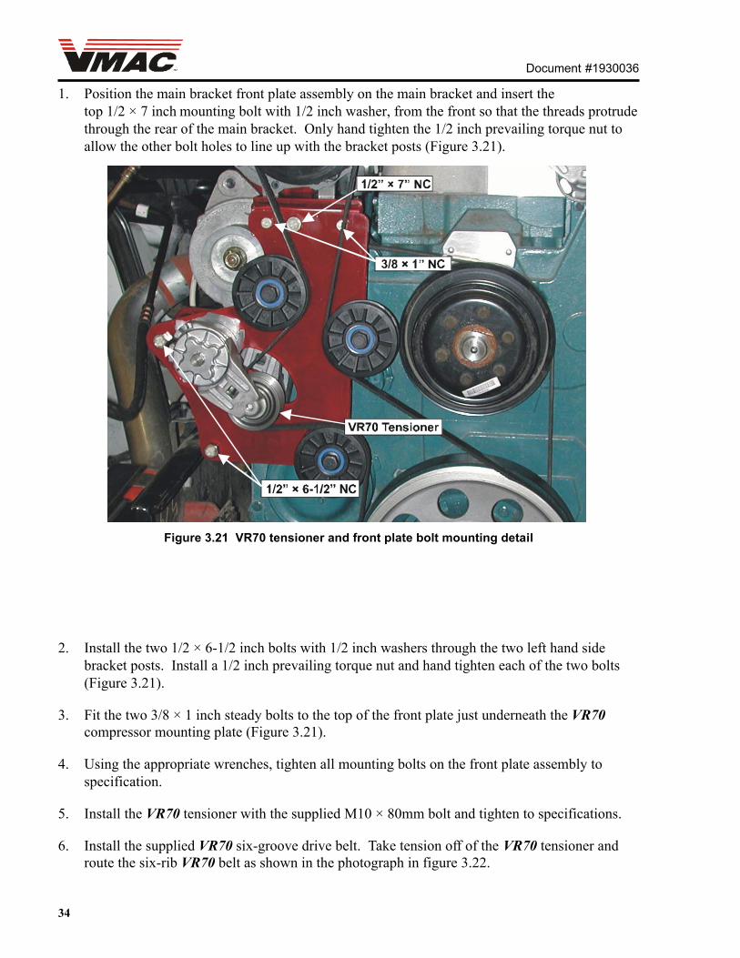
1. Position the main bracket front plate assembly on the main bracket and insert thetop 1/2 × 7 inch mounting bolt with 1/2 inch washer, from the front so that the threads protrudethrough the rear of the main bracket. Only hand tighten the 1/2 inch prevailing torque nut toallow the other bolt holes to line up with the bracket posts (Figure 3.21).
Figure 3.21 VR70 tensioner and front plate bolt mounting detail
2. Install the two 1/2 × 6-1/2 inch bolts with 1/2 inch washers through the two left hand sidebracket posts. Install a 1/2 inch prevailing torque nut and hand tighten each of the two bolts(Figure 3.21).
3. Fit the two 3/8 × 1 inch steady bolts to the top of the front plate just underneath the VR70compressor mounting plate (Figure 3.21).
4. Using the appropriate wrenches, tighten all mounting bolts on the front plate assembly tospecification.
5. Install the VR70 tensioner with the supplied M10 × 80mm bolt and tighten to specifications.
6. Install the supplied VR70 six-groove drive belt. Take tension off of the VR70 tensioner androute the six-rib VR70 belt as shown in the photograph in figure 3.22.

Document #1930036
35
3.9 Adding oil to the system
1. Make sure that the vehicle is level.
2. Remove the oil filler plug from the inlet control valve (Figure 3.23).
3. Pour the supplied compressor oil into the filler hole using a funnel.
You must use the supplied compressor oil in this system. Failure to use thisspecial oil will result in damage to the compressor and will void your warranty.
4. Turn the compressor clutch clockwise with a ratchet and socket using the hex head bolt at thecenter of the compressor clutch as you pour in the oil.
5. Check the sight glass window at the front of the tank regularly to ensure that the correct oillevel is attained. It is important not to overfill the system.
6. Insert the filler plug in the inlet control valve and tighten to specifications.
Figure 3.22 VR70 belt routing after installation

36
Document #1930036
Figure 3.23 Oil fill detail
3.10Completing the installation
1. Use the original screws that secured the compressor belt guard to install the compressor beltguard back on the compressor inlet control valve.
2. Refill the coolant in the radiator that was drained in the �Preparation for installation� section ofthe manual.
3. Reconnect the intercooler pipe to the intercooler.
4. Reconnect the trunking from the turbo charger to the air cleaner. Leave fasteners and clampsonly hand tight to allow for an easier fitting of the air cleaner filter box.
5. Reinstall the air cleaner filter box and tighten all clamps and applicable fasteners.
To avoid disconnection of the air cleaner boot from the air cleaner filter box, itis advised that this part of the component should not be used as a grip or apoint of leverage when the box is reinstalled.
6. Reinstall the air filter and air filter retainer cap.
7. Reinstall the plastic left fender well using the four OEM M8 bolts and washers.

SYSTEM #V900068
INTERNATIONAL 2001 - 20034300, 4400 SERIES DT466
UNDERHOOD AIR COMPRESSOR
TM
PART 4
INSTALLING THE CONTROLCOMPONENTS

Document #1930036
38

Document #1930036
39
4.1 Installing the control unit
1. Remove the screws holding the plastic protector panel in place on the floor inside the driver�sdoor. Remove the panel.
2. Remove the rear seat rail bolt and fasten the bracket to the floor using the bolt through the rear-most hole (Figure 4.1).
Figure 4.1
3. Cut a small slot in the rubber floor mat where the control unit will mount so that you can routethe wires under the mat from the back of the unit.

Document #1930036
40
4. Mount the control unit to the bracket with the four supplied sheet metal screws (Figure 4.2).Position it with the wire harness coming out from the bottom of the unit (Figure 4.3). Feed theharness through the hole in the floor mat, along the floor and up under the dash.
Figure 4.3
Figure 4.2

Document #1930036
41
Figure 4.4
4.2 Connecting the wiring

Document #1930036
42
1. Connect the two interface cable connectors. A wiring diagram is shown in figure 4.4. Tape upthe yellow �DDC� wire and tie it up under the dash.
2. Connect the green wire with the ring connector to a good ground.
3. Route the red wire with the fuse holder under the dash to the fuse panel. Locate an empty fuseconnection and install the red wire using the fuse holder connector.
4. Locate a fuse in the fuse panel that will provide power only when the ignition switch is in the�ON� position (Figure 4.5).
Figure 4.5
5. Locate a grommet or other opening in the firewall and feed the white wire from the interfacecable and the grey cable from the control panel, through to the engine compartment. Connectthe white wire to the matching connector at the compressor clutch, and the grey cable to thetemperature probe cable.
6. Leave the red wire under the dash near the throttle pedal for connection to the throttle control.
7. Replace the doorsill trim at the driver�s door.
8. Replace the fuse panel cover.

Document #1930036
43
4.3 Installing the throttle
1. Using the supplied nylon ties, mount the throttle up under the dash near the accelerator pedal.Keep the adjustment screws accessible.
2. Disconnect the OEM connector at the accelerator pedal position sensor, and connect it to theconnector on the throttle.
3. Connect the black throttle connector to the accelerator pedal position sensor.
4. Route the red throttle wire to the red wire from the interface cable that was set aside in section4.2, step 6. Connect these wires.
5. Connect the green �Ground inch wire from the throttle to a good ground.
6. Route the grey �Pressure sensor� cable from the throttle through the firewall to the compressor,alongside the white �Clutch� wire and connect it to the pressure sensor on the inlet controlvalve.
7. Cover the wires in the engine compartment with the supplied split loom.
4.4 Hydraulic brakes
1. Locate the black and white park brake wires that route under the floor mat from the park brakeand come up beside the accelerator pedal (Figure 4.6).
Figure 4.6

Document #1930036
44
4.4.1Hydraulic brakes and standard transmission
Figure 4.7
1. Disconnect the OEM connector and reconnect it to the mating connectors on the �ParkingBrake� black interface cable wire (Figure 4.7).
4.4.2Hydraulic brakes and automatic transmission
1. Connect the �VR black� wire on the Drive Disable Circuit. (DDC) to the black wire onthe interface cable.
Figure 4.8

Document #1930036
45
2. Disconnect the OEM connector and reconnect it to the mating connectors on the �Parkingbrake� black DDC wire (Figure 4.8).
3. Locate the connector shown in Figure 4.9.
Figure 4.9
4. Locate the pink wire labeled �L17E� at pin �G� of the connector shown at thetransmission (Figure 4.9).
5. Solder the blue DDC wire to the pink wire labeled �L17E� on pin �G� as shown inAppendix A.
VMAC recommends that all wire connections be soldered for reliability. AT-Tap connector has been supplied if this is not practical.
4.5 Final testing and assembly
1. Block the wheels of the vehicle. Apply the park brake, and if it is an automatic, put thetransmission in neutral.
2. With the battery reconnected, turn the ignition to the �Run� position.
Do not start the engine.
3. Turn �On� the control panel. The green light should come �On�.
4. Release the park brake. The green light should go off.
5. Reapply the park brake.
6. If the truck is an automatic, shift into gear. The green light should go �Off�.

Document #1930036
46
7. Shift back to �Neutral�. The green light should come back �On�.
8. Turn off the control panel. Shift the transmission into gear.
9. Turn on the control panel. The green light should not come �On�.
10. Shift back to �Neutral�. The green light should come �On�.
11. Turn off the control panel and ignition.
12. Secure the wires in place under the dash and make sure that none of the wires interfere withany moving parts.
Document #1930036
47
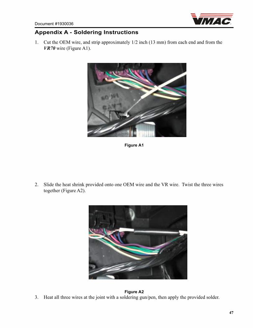
Appendix A - Soldering Instructions
1. Cut the OEM wire, and strip approximately 1/2 inch (13 mm) from each end and from theVR70 wire (Figure A1).
Figure A1
2. Slide the heat shrink provided onto one OEM wire and the VR wire. Twist the three wirestogether (Figure A2).
Figure A23. Heat all three wires at the joint with a soldering gun/pen, then apply the provided solder.

48
Document #1930036
4. Slide the heat shrink over the joint, and shrink onto the joint using a heat gun. Make sure theshrink is heated until the liner melts and makes a good seal (Figure A4).
Figure A4
Ensure the solder �flows� into the joint to bond the wires together (Figure A3).
Figure A3

SYSTEM #V900068
INTERNATIONAL 2001 - 20034300, 4400 SERIES DT466
UNDERHOOD AIR COMPRESSOR
TM
PART 5
ILLUSTRATED PARTS LIST

Document #1930036
50
Document #1930036
51
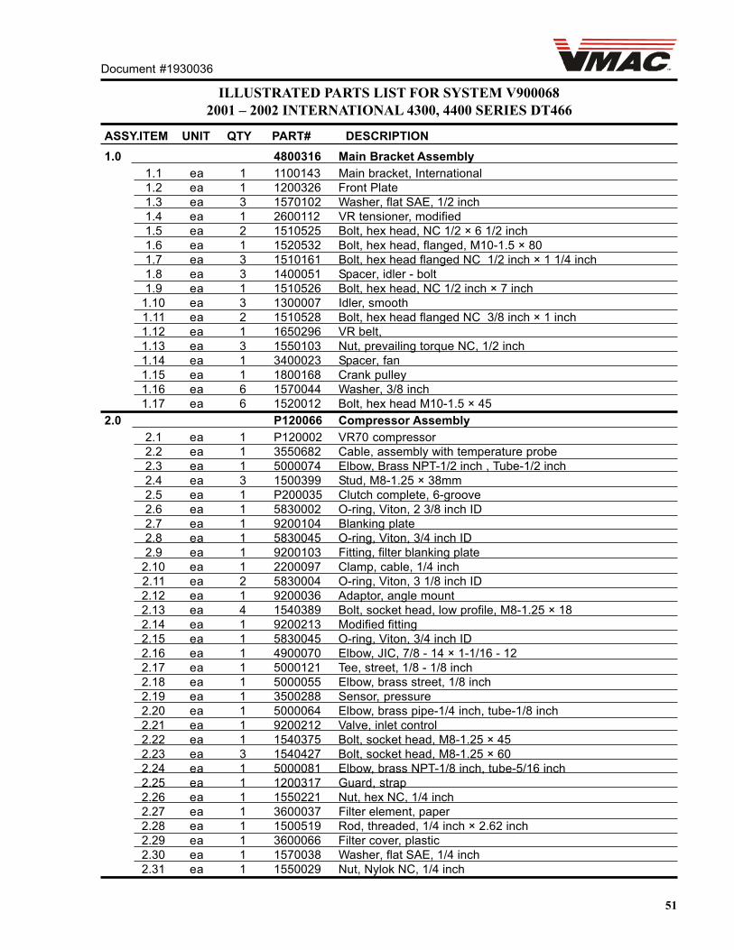
ILLUSTRATED PARTS LIST FOR SYSTEM V9000682001 � 2002 INTERNATIONAL 4300, 4400 SERIES DT466
ASSY.ITEM UNIT QTY PART# DESCRIPTION1.0 4800316 Main Bracket Assembly
1.1 ea 1 1100143 Main bracket, International1.2 ea 1 1200326 Front Plate1.3 ea 3 1570102 Washer, flat SAE, 1/2 inch1.4 ea 1 2600112 VR tensioner, modified1.5 ea 2 1510525 Bolt, hex head, NC 1/2 × 6 1/2 inch1.6 ea 1 1520532 Bolt, hex head, flanged, M10-1.5 × 801.7 ea 3 1510161 Bolt, hex head flanged NC 1/2 inch × 1 1/4 inch1.8 ea 3 1400051 Spacer, idler - bolt1.9 ea 1 1510526 Bolt, hex head, NC 1/2 inch × 7 inch
1.10 ea 3 1300007 Idler, smooth1.11 ea 2 1510528 Bolt, hex head flanged NC 3/8 inch × 1 inch1.12 ea 1 1650296 VR belt,1.13 ea 3 1550103 Nut, prevailing torque NC, 1/2 inch1.14 ea 1 3400023 Spacer, fan1.15 ea 1 1800168 Crank pulley1.16 ea 6 1570044 Washer, 3/8 inch1.17 ea 6 1520012 Bolt, hex head M10-1.5 × 45
2.0 P120066 Compressor Assembly2.1 ea 1 P120002 VR70 compressor2.2 ea 1 3550682 Cable, assembly with temperature probe2.3 ea 1 5000074 Elbow, Brass NPT-1/2 inch , Tube-1/2 inch2.4 ea 3 1500399 Stud, M8-1.25 × 38mm2.5 ea 1 P200035 Clutch complete, 6-groove2.6 ea 1 5830002 O-ring, Viton, 2 3/8 inch ID2.7 ea 1 9200104 Blanking plate2.8 ea 1 5830045 O-ring, Viton, 3/4 inch ID2.9 ea 1 9200103 Fitting, filter blanking plate
2.10 ea 1 2200097 Clamp, cable, 1/4 inch2.11 ea 2 5830004 O-ring, Viton, 3 1/8 inch ID2.12 ea 1 9200036 Adaptor, angle mount2.13 ea 4 1540389 Bolt, socket head, low profile, M8-1.25 × 182.14 ea 1 9200213 Modified fitting2.15 ea 1 5830045 O-ring, Viton, 3/4 inch ID2.16 ea 1 4900070 Elbow, JIC, 7/8 - 14 × 1-1/16 - 122.17 ea 1 5000121 Tee, street, 1/8 - 1/8 inch2.18 ea 1 5000055 Elbow, brass street, 1/8 inch2.19 ea 1 3500288 Sensor, pressure2.20 ea 1 5000064 Elbow, brass pipe-1/4 inch, tube-1/8 inch2.21 ea 1 9200212 Valve, inlet control2.22 ea 1 1540375 Bolt, socket head, M8-1.25 × 452.23 ea 3 1540427 Bolt, socket head, M8-1.25 × 602.24 ea 1 5000081 Elbow, brass NPT-1/8 inch, tube-5/16 inch2.25 ea 1 1200317 Guard, strap2.26 ea 1 1550221 Nut, hex NC, 1/4 inch2.27 ea 1 3600037 Filter element, paper2.28 ea 1 1500519 Rod, threaded, 1/4 inch × 2.62 inch2.29 ea 1 3600066 Filter cover, plastic2.30 ea 1 1570038 Washer, flat SAE, 1/4 inch2.31 ea 1 1550029 Nut, Nylok NC, 1/4 inch

Document #1930036
52
ILLUSTRATED PARTS LIST FOR SYSTEM V9000682001 � 2002 INTERNATIONAL 4300, 4400 SERIES DT466
ASSY.ITEM UNIT QTY PART# DESCRIPTION5.0 3560086 Throttle Control
5.1 ea 1 3550388 Control box5.2 ea 1 3560086 Throttle5.3 ea 1 3550660 Interface cable5.4 ea 1 3550663 Drive disconnect circuit (DDC)5.5 ea 1 1200325 Bracket, control panel
ASSY.ITEM UNIT QTY PART# DESCRIPTION4.0 Hose Kit
4.1 ea 1 1771076 Hose, crimped, 3/4 × 76 inch4.2 ea 1 1740111 Hose, crimped, 5/16 × 111 inch4.3 ea 1 1730111 Hose, crimped, 1/4 × 111 inch4.4 ea 1 1752048 Hose, crimped, 1/2 × 48 inch4.5 ea 1 1752032 Hose, crimped, 1/2 × 32 inch4.6 ea 1 1710637 Hose, heater 1 × 120 inch4.7 ea 1 5000015 Barb, 3/4 × 1 inch4.8 ea 8 2200047 Hose clamp, HS-164.9 ea 5 2200029 Hose clamp, HS-10
4.10 ea 2 5300041 T-barb, 1 × 1 × 3/4 inch4.11 ea 1 1710577 Hose assembly4.12 ea 1 1720577 Diverter tube assembly4.13 ea 2 2200158 Hose clamp, HS-404.14 ea 1 5000138 Elbow,Brass xtrd street 45D,3/4 NPT4.15 ea 1 1710644 Hose, Heater, 3/4 X 100" (1700177)4.16 ea 1 5000016 Barb, 3/4x3/4 inch
ASSY ITEM UNIT QTY PART # DESCRIPTION3.0 9200380 Tank Assembly
3.1 ea 1 9200378 Oil Separator Tank Weldment3.2 ea 1 5000089 3/8 NPT � 1/2 SAE Brass Connector3.3 ea 1 4900035 Nipple, Steel, Straight Thread, 3/4-163.4 ea 1 5830043 O-ring, Viton 1-7/8 ID x 1/83.5 ea 1 9200039 VR70 Oil Filter3.6 ea 1 1500385 Retaining Ring3.7 ea 1 1400235 Ring, 2.12 OD x 1.72 ID x .153.8 ea 1 3600096 Window, Pyrex, 2.12 dia. x .35 thick3.9 ea 1 3600054 200 PSI Relief Valve3.10 ea 1 4900033 3/4 NPT � 3/4 JIC Steel Connector3.11 ea 1 5830066 O-ring, Viton, 4-3/4 ID3.12 ea 1 5840068 Compression Spring3.13 ea 1 3600036 Coalescing Filter Element3.14 ea 1 3600064 Tank Rear Cap Seal3.15 ea 1 3600090 Thimble Screen3.16 ea 1 5840069 Spring, Compression, FL 1.5 OD-543.17 ea 1 9200217 Blowdown Cap3.18 ea 1 3200231 Cover, Sight Glass

Document #1930036
53
ILLUSTRATED PARTS LIST FOR SYSTEM V9000682001 � 2002 INTERNATIONAL 4300, 4400 SERIES DT466
ASSY.ITEM UNIT QTY PART# DESCRIPTION6.0 Tank Bracket Assembly
6.1 ea 2 1200318 Bracket, tank mount6.2 ea 2 2200144 Cable, tank strap6.3 ea 2 1570476 Washer, 5/16 inch ID 3/4 inch OD6.4 ea 4 1550066 Nut, hex NC 5/16 inch6.5 ea 2 2200105 Clamp mounting bracket6.6 ea 1 4800257 Hose support clamp assembly
ASSY.ITEM UNIT QTY PART# DESCRIPTION7.0 Cooler Assembly
7.1 ea 1 9200235 Cooler
ASSY.ITEM UNIT QTY PART# DESCRIPTION8.0 Miscellaneous
8.1 ea 1 1200316 Bracket braceea 1 A700091 Oil VR high performance, 1 litreea 1 A700094 Oil VR high performance, 4 litre
ASSY.ITEM UNIT QTY PART# DESCRIPTION9.0
9.1 ea 1 4300006 Plug, 3/4 pipe fitting