system requirements - minnesota department of … · february 2, 2015 page 4 system requirements...
TRANSCRIPT

System Requirements prepared for
Minnesota Department of Transportation (MnDOT)
for
Rural Intersection Conflict Warning Systems II Deployment
February 2, 2015

February 2, 2015 Page 1
Acknowledgements These system requirements were originally developed by MnDOT for the statewide Rural Intersection
Conflict Warning System (RICWS) project in October 2012. Carver County asked SRF Consulting Group to
revise this document to incorporate lessons learned from the RICWS project to enable the installation of
additional Intersection Conflict Warning Systems (ICWS) on T.H. 212 in Carver County. MnDOT
participated in the development of this project and the associated systems engineering documents.
These systems requirements were then revised by SRF Consulting Group for use on MnDOT’s second
deployment Rural Intersections Conflict Warning Systems II (RICWS II).
Introduction The primary goal of an ICWS system is to reduce right angle crashes at a stop-controlled intersection.
These systems address crashes at stop-controlled intersections by providing drivers with a dynamic
warning of other vehicles approaching or entering the intersection. ICWS typically consist of static
signing, detection and dynamic elements as illustrated in Figure 1.
As they are currently conceived, ICWS fit within Minnesota’s ITS architecture under the Advanced
Vehicle Safety Systems market packages AVSS05-Intersection Safety Warning and AVSS10-Intersection
Collision Avoidance.
Figure 1 Intersection Conflict Warning System Concept

February 2, 2015 Page 2
This document presents detailed system requirements for ICWS systems. These requirements are based
on MnDOT experience to-date with ICWS and they will evolve as more is learned.
Definitions Intersection – as defined in the MUTCD, Part 1. General, Section 1A.13 Definitions of Headings, Words,
and Phrases in this Manual:
a) The area embraced within the prolongation or connection of the lateral curb lines, or if not, the
lateral boundary lines of the roadways of two highways that join one another at, or
approximately at, right angles or the area within which vehicles traveling on different highways
that join at any other angle might come into conflict.
b) The junction of an alley or driveway with a roadway or highway shall not constitute an
intersection, unless the roadway or highway at said junction is controlled by a traffic control
device.
c) If a highway includes two roadways that are 30 feet or more apart (see definition of median),
then every crossing of each roadway of such divided highway by an intersection highway shall
be a separate intersection.
d) If both intersecting highways include two roadways that are 30 feet or more apart, then every
crossing of any two roadways of such highway shall be a separate intersection.
Approaching Vehicle – a motor vehicle that is approaching the intersection which is on:
a) The minor road and at some point was more than time “t” from the intersection.
b) The major road and at some point was more than the major road lag time from the intersection.
Entering Vehicle – a motor vehicle that turns onto the minor road less than the time “t” from the
intersection or a motor vehicle that enters the major road less than the major road lag time from the
intersection.
Operational Malfunction – component failures and malfunctions of otherwise functional hardware and
software that prevents the RICWS system from displaying alerts to any approaching vehicle within
parameters defined in these system requirements.
System Availability – is the design life of the system divided by the design life plus the average repair
time per year (Design Life/(Design Life+(Repair Time*Average Failures per Year). See Appendix B for
system availability discussion.
System Repair Time – is defined as a 72 hour allowable window for response to a reported operational
malfunction.

February 2, 2015 Page 3
Time “t” – a single constant for the intersection and is the largest time computed based on the major
road vehicle lag time from 2.5 seconds in advance of the major road warning sign to the intersection at
the posted speed limit.
User – Refers to Contractor or Agency field personnel on site.
User-configurable - is the parameter that allows engineering judgment of how best to establish
detection and alert activation parameters based on traffic characteristics (gap selection, sight distance,
and speed of each approaching vehicle) at a given intersection.
Vehicles – For the purpose of these requirements the term vehicles shall mean motor vehicles as
defined in Minnesota Statutes and the Minnesota Manual on Uniform Traffic Control Devices.
Major Road Lag time - the portion of the gap which remains from the major road vehicle to the minor
road vehicle at the stop line. This is further defined in NCHRP Report 383, Intersection Sight Distance.

February 2, 2015 Page 4
System Requirements System requirements are verifiable details that define what the intersection conflict warning system will do. They address either functional or
performance/operational aspects of the system and are noted as such in the following table. Each of the high level requirements below was
originally translated from stakeholder needs identified in the project Concept of Operations. The number references allow for traceability back
to those needs and forward to the detailed system requirements. The first number refers to one of three stakeholder need categories – Driver
Alerts, Traffic Control or Assessment and Evaluation. The second number refers to the stakeholder needs as they were presented in the Concept
of Operations. The third number is used to track high level requirements and the final reference number relates to detailed system
requirements, where applicable. Some reference numbers may also be out of sequence because the stakeholder needs that originally prompted
them were performance or operationally oriented and therefore more appropriately addressed in project contract documents rather than
functional requirements.
Number High Level Requirements Number Detailed System Requirements
1 Driver Alerts
1.1.1 ICWS shall detect vehicles approaching and waiting
at the stop or yield signs on the minor road.
1.1.1.1 ICWS shall detect approaching vehicles from both directions on the
minor road as they are approaching the intersection less than time t,
from the intersection.
1.1.1.2 ICWS shall detect any vehicle on the minor road that is waiting at the
stop or yield sign on the minor road.
1.1.1.3 ICWS shall be capable of detecting all entering vehicles on the minor
road as they turn onto the minor road. Design considerations for
including this detection at specific sites are included in the attached
Design Guidelines.
1.1.2 ICWS shall display alerts to major road drivers
whenever a vehicle is approaching or waiting at the
stop or yield sign on the minor road.
1.1.2.1 ICWS alert shall be active on the major road whenever any
approaching vehicle on the minor road is less than time “t” away
from the stop sign.
1.1.2.2 ICWS alert shall be active on the major road whenever any vehicle
on the minor road is waiting at the stop or yield sign.

February 2, 2015 Page 5
Number High Level Requirements Number Detailed System Requirements
1.1.2.3 ICWS alert shall be active on the major road whenever any vehicle
from the minor road is within the intersection.
1.1.2.4 ICWS alert shall be active on the major road whenever any vehicle
on the minor road is waiting at the median yield sign.
1.1.2.5 ICWS alert shall be inactive on the major road whenever:
there are no approaching vehicles on the minor road less
than time “t” away from the intersection;
there are no vehicles waiting at the stop sign;
there are no minor road vehicles within the intersection; and
there are no vehicles waiting at the median yield sign.
1.1.2.6 System activation and de-activation based on time “t” shall be within
± 0.5 seconds of time “t”.
1.1.2.7 ICWS shall respond with at least 99.95% accuracy for major road
alerts.
1.1.3 ICWS may display an alert for major road drivers
even if no major road vehicles are present.
No further detail required.
1.2.1 ICWS alerts shall be visible to major road drivers at
a distance that allows them to take corrective
action.
1.2.1.1 ICWS alerts shall be visible from any approach lanes on the major
road.
1.2.1.2 ICWS alerts shall be placed on the major road according to MN
MUTCD Part 2C. Warning Signs and Object Markers, Section 2C.05
Placement of Warning Signs, and using Table 2C-4. Guidelines for
Advance Placement of Warning Signs.
1.3.1 ICWS shall detect all vehicles as they approach the
intersection on the major road.
1.3.1.1 ICWS shall detect any approaching vehicle from both directions, in
all lanes, as they are approaching the intersection within a user-
configurable lag time on the major road.

February 2, 2015 Page 6
Number High Level Requirements Number Detailed System Requirements
1.3.1.2 ICWS shall be capable of detecting all entering vehicles on the major
road as they enter the major road. Design considerations for
including this detection at specific sites are included in the attached
Design Guidelines.
1.3.2 ICWS shall display alerts to minor road drivers
whenever vehicles approach the intersection on the
major road.
1.3.2.1 ICWS alert shall be active on the minor road whenever any
approaching vehicle on the major road is less than a user-
configurable lag time away from the intersection.
1.3.2.2 ICWS alert shall be active on the minor road whenever any major
road approaching vehicle is within the intersection.
1.3.2.2 ICWS alert shall be inactive on the minor road whenever there are
no approaching vehicles less than a user-configurable lag time away
from the intersection on the major road.
1.3.2.3 ICWS alert shall allow a user-configurable lag time between 4 and
7.5 seconds, in increments of 0.1 seconds, for any approaching
vehicle on the major road. The lag time will define active/inactive
parameters for the minor road alert.
1.3.2.4 ICWS alert lag-time shall allow for user configuration of lag time on
the major road by changing parameters within the system software
and without changes to detector placement, hardware, or
firmware/software programing
1.3.2.5 ICWS shall meet requirements for user-configurable active and
inactive lag timing whenever any approaching vehicle speed is
within ±12 MPH of the posted speed on the major road; excluding
vehicles that may be decelerating to execute a turn at the
intersection.
1.3.2.6 System activation and de-activation based on user configurable lag
time shall be within +/- 0.5 seconds of the lag time the user has
configured.

February 2, 2015 Page 7
Number High Level Requirements Number Detailed System Requirements
1.3.1.2 ICWS shall respond with at least 99.95% accuracy for minor road
alerts.
1.3.3 ICWS may display an alert for minor road drivers
even if no minor road vehicles are present.
No further detail required.
1.4.1 ICWS shall display alerts at a location visible to
minor road drivers waiting at the stop sign.
1.4.1.1 ICWS alert shall be placed on far right corner of intersection, across
from the stop sign, where intersection geometry permits. For those
intersections with restricted geometry, ICWS alert may be placed on
far left corner of intersection, across from the stop sign.
1.5.1 ICWS design shall include dynamic alerts. No further detail required.
1.6.2 To the extent possible, ICWS shall follow
recommended design practices described in “Design
and Evaluation Guidance for Intersection Conflict
Warning Systems” authored by the ENTERPRISE
Transportation Pooled Fund program.
1.6.2.1 ICWS shall be designed using the placement, sign combinations and
message sets described for Major and Minor Road Alert for 2-
Lane/2-Lane (or Multi-Lane) Intersection or for a major road alert
only.
1.7.1 ICWS shall have similar placement, sign
combinations and message sets at each deployment
site in Minnesota.
1.7.1.1 ICWS alert shall use TRAFFIC APPROACHING WHEN FLASHING (W3-
X8b) sign(s) on the minor roadway. The ICWS alert shall use either
ENTERING TRAFFIC WHEN FLASHING (W3-X8a and W3-X8aP) on
two-lane two-way major roadway or ENTERING TRAFFIC WHEN
FLASHING (W3-X8) on multi-lane divided major roadway.
1.7.1.2 The TRAFFIC APPROACHING WHEN FLASHING (W3-X8b) sign(s) on
the minor roadway shall be a blank out sign allowing the sign to be
de-energized by the control system or user. This allows a
malfunctioning system to appear different than an inactive system.
1.8.1 ICWS alerts shall be conspicuous. 1.8.1.1 ICWS alert shall conform to MN MUTCD 2A.7 Retroreflectivity and
Illumination, MN MUTCD 2L.4 Design Characteristics of Changeable
Message Signs, and TEM 6-4.05.05 Retroreflective Sheeting Policy
for sign sheeting materials and LED brightness.

February 2, 2015 Page 8
Number High Level Requirements Number Detailed System Requirements
2 Traffic Control
2.1.1 ICWS shall function as a warning sign as defined in
MN MUTCD 2C.1-2C.2.
No further detail required.
2.2.1 ICWS shall operate continuously 24x7, 365 days per
year, with minimal service interruption.
2.2.1.1 The system shall operate continuously 24 hours per day, 365 days
per year during its design life of 10 years (87,600 hours) without the
need for restarts, re-initializations for other external interventions.
2.2.1.2 The system shall have availability over its design life greater than
99.9% as defined in these requirements.
2.2.1.3 ICWS components shall conform to NEMA TS 2-2003 environmental
requirements.
2.2.1.4 ICWS alert shall conform to NEMA TS 4-2005 standards for the
hardware and functional characteristics of electronically controlled
dynamic message signs, if used.
2.2.1.5 ICWS shall be connected to utility power service.
2.2.1.6 ICWS shall detect any detection component malfunction.
2.2.1.7 ICWS system communication components shall comply with FCC
emission requirements. The system shall be able to meet needed
FCC approvals when design is complete.
2.2.1.8 ICWS Control Cabinet shall meet the requirements of UL 508
“Standard for Industrial Control Equipment”, January 28th 1999
Edition, and the requirements of the current edition of the National
Electrical Code by either being listed by a Nationally Recognized
Testing Laboratory (NRTL) or being certified under Minnesota Rule
3801.3620 Subpart 3 D 1, that the ICWS Control Cabinet is safe for
its intended purpose.
2.2.1.9 In the event of a power failure, the ICWS system shall restart
automatically upon restoration of power.

February 2, 2015 Page 9
Number High Level Requirements Number Detailed System Requirements
2.2.1.10 Restoration of power shall not reset a system malfunction that was
previously active.
2.2.2 ICWS shall not depend on communication with
external systems to operate.
No further detail required.
2.3.1 ICWS shall display a visible indication of
malfunction.
2.3.1.1 ICWS shall display indication of malfunction within 1 minute of
detection.
2.3.2 ICWS indication of malfunction shall be visibly
different than ICWS in any other active or inactive
state.
2.3.2.1 ICWS malfunction indication on the major road alert shall consist of
continuous activation of the flashing beacon, excluding utility power
service failure. If utility power service fails, it is acceptable for
beacon to just be off.
2.3.2.2 ICWS malfunction indication on the minor road alert using a blank-
out sign shall have no visible legend and flashing beacons shall be
de-energized.
2.3.3 ICWS indication of malfunction shall be
distinguishable without knowledge of ICWS
operations
No further detail required.
2.4.1 ICWS shall not obstruct any drivers’ view of the
roadway, other vehicles or regulatory signs.
No further detail required.
2.5.1 ICWS shall meet MN MUTCD Section 2A.21 Posts
and Mountings standard and AASHTO Specification
for Structural Supports for Highway Signs,
Luminaires and Traffic Signals for crashworthiness.
No further detail required.
2.5.2 ICWS shall consist of materials and be installed as
specified in Section 2564 Traffic Signs and Devices
and Section 2565 Traffic Control Signals of the
MnDOT Standards Specifications for Construction.
No further detail required.
2.6.1 ICWS design shall be maintainable and fit within
Agency maintenance processes.
No further detail required.

February 2, 2015 Page 10
Number High Level Requirements Number Detailed System Requirements
2.7.1 ICWS design shall follow design practices that allow
maintenance staff familiar with other statewide
ICWS systems to operate and maintain the system.
No further detail required.
2.8.1 ICWS shall have consistent cabinet layout and one
central programmable control unit that is the same
for each site to allow major road only, minor road
only or major/minor road alerts as defined in Section
17 of Book 2.
2.8.1.1 ICWS shall allow a minor road only system to be added to a major
road system and provide combined alert to both major and minor
road drivers.
2.8.1.2 ICWS shall allow a major road only system to be added to a minor
road system and provide combined alerts to both major and minor
road drivers.
2.8.1.3 ICWS shall allow the minor or major road alert to be removed from
a combined major and minor road alert and provide alerts to only
the major or minor road drivers, respectively.
2.9.1 ICWS physical components shall be physically
accessible for maintenance with one transportation
agency vehicle and a 1-2 person crew in the right of
way.
2.9.1.1 ICWS control cabinet shall be located in an intersection quadrant
that provides easy access by service personnel including proximity to
parking of vehicle and easy walking path to cabinet. The control
cabinet shall be situated so service personnel can readily see the
intersection and related components when standing in front of the
cabinet door. The cabinet door shall also be situated to provide easy
access during all seasons (e.g. minimal snow and ice during winter,
vegetation during summer, etc.) Any pole/post mounted equipment
shall be accessible from the shoulder of the roadway, or if no
shoulder from the nearest traffic lane, by a bucket truck with a 52
foot maximum reach.
3 Assessment and Evaluation
3.1.1 Systems engineering documentation shall explain No further detail required.

February 2, 2015 Page 11
Number High Level Requirements Number Detailed System Requirements
safety considerations for ICWS.
3.2.1 ICWS design shall be compatible with other
statewide ICWS systems such that the design,
construction, operation and maintenance
procedures can be implemented.
No further detail required.
3.3.1 ICWS shall collect and retain data about system
performance that indicates when and what
components have failed or may be operating in less
than optimal states.
3.3.1.1 ICWS shall maintain an internal record of detection and power
failures and a corresponding time/date stamp for when the failure
began and ended.
3.3.1.2 ICWS shall maintain an internal record of individual system
activations with a time/date stamp during a 96 hour period.
3.3.1.3 ICWS shall maintain an internal record of individual vehicle
detections with a time/date stamp during a 96 hour period.
3.3.2 ICWS shall have remote communication and
monitoring capabilities that allow for determining if
the system is operational or in a failure state.
3.3.2.1 The remote communications monitoring capabilities shall conform
to and provide for NTCIP 1202 and include the ability to report
detector diagnostics; no activity, maximum presence, and erratic
counts (all with settable values).

February 2, 2015 Page A-1
Appendix A: Design Consideration and Guidance
TIME “T” FOR MAJOR ROAD ALERT
Time “t” – a single constant for the intersection and is the largest time computed based on the major
road vehicle lag time from 100 feet in advance of the major road warning sign to the intersection at the
posted speed limit. Distances are based on the typical condition for deceleration to the listed advisory
speed for the warning of a potential stop situation as defined in MUTCD Table 2C-4. The distances are
based on the 2005 AASHTO Policy, Exhibit 3-1, Stopping Sight Distance, providing a PRT (Perception-
Response Time) of 2.5 seconds, a deceleration rate of 11.2 feet/second2, minus the sign legibility
distance of 180 feet. The distances shown in Table 2C-4 are provided as an aid for determining the
minimum sign location to the intersection. MnDOT’s Traffic Engineering Manual Chapter 6, specifically
Figures 6.24, 6.25 and 6.26, provides for standard sign location, order, and spacing for the major road
warning signs. An illustration of how time t may be applied is provided in Appendix A for ICWS 3 and
ICWS 4.
USER CONFIGUABLE LAG TIME FOR MINOR ROAD ALERT
Posted Speed
Limit, -12 MPH Posted Speed
Limit Posted Speed
Limit, +12 MPH Active Alert Timing and Distance
(User-Configurable Lag Time) 4 Seconds 6.5 Seconds 7.5 Seconds
43 MPH 252’ 410’ 473’
55 MPH 323’ 524’ 605’
67 MPH 393’ 639’ 737’
This table illustrates sample calculations initially used by the Minnesota Department of Transportation
(MnDOT) to define a user-configurable lag time range for the timing and distance necessary to activate
an alert on the minor road. The range for the user-configurable lag time is based on deployment
experience in Minnesota. MnDOT established the range by starting with a 6.5 second gap rejection
threshold. This threshold is based on research cited in, “Alert and Warning Timing for CICAS-SSA – An
Approach Using Macroscopic and Microscopic Data: Cooperative Intersection Collision Avoidance
System-Stop Sign Assist Report #1.” The research showed that 6.5 seconds represents the average
weighted 80% gap rejection threshold in Minnesota and Wisconsin. MnDOT added a +1.0 second/-2.5
second buffer to the gap rejection threshold, considered a 55 MPH posted speed limit, and allowed for
vehicles traveling ±12 MPH within the limit. Calculation details are included in the table. The range for
the user - configurable lag time may be adjusted as needed for individual deployments, but establishing
a range is strongly encouraged to constrain design costs.

February 2, 2015 Page A-2
DRIVEWAY DETECTION
While most system activations are caused by Approaching Vehicles (vehicles that that enter the Active
Zone as they approach the intersection), there may be driveways adjacent to the active zone that
require Entering Vehicles (vehicles that enter the Active Zone from adjacent driveways or roads) to be
detected. Consideration should be given to detecting and responding to these Entering Vehicles if they
are from commercial, retail, industrial and other publically accessed driveways or roads. This
consideration should include, among other items, the distance and time to the intersection, volume of
traffic, and type of entering vehicles. Detection of Entering Vehicles from residential and other private
driveways may be disregarded based on engineering judgment.
TURN ON TEST AND ACCEPTANCE TEST
Project documents shall include requirements for an initial turn on test before systems are “turned-on”
and put into service. It is suggested that each system have a 90 day acceptance/break-in period
included in the project documents. During this period the Contractor shall be responsible for any and all
repairs that are due to workmanship and quality of the equipment and installation. This excludes
damage due to vandalism, traffic crashes, or natural disasters that are outside of the control of the
Contractor and Manufacturer. At this end of this 90 day acceptance period an acceptance test, similar
to, if not identical to the turn on test, should be conducted before turning ownership, maintenance and
operation to the road authority.

February 2, 2015 Page B-1
Appendix B: System Availability and Reliability
Reliability Requirements Overview
Defining system reliability in a consistent and quantifiable way is one of the most difficult aspects of
creating functional requirements. The lack of historical data for the overall reliability of newly
integrated systems and the limitations of combining mean time to failure (MTTF) figures provided by
manufactures make defining reliability in an objective way challenging.
In reliability engineering, one of the most basic specifications is the Inherent Availability (Ai) which is
defined as the probability that a system will operate properly under ideal conditions at a given point in
time. Ai is calculated by dividing the Mean Time To Failure (MTTF) by the sum of MTTF and the Mean
Time To Repair (MTTR). The outage time for a system is then 1/MTTF. This calculation will then
produce the equivalent of an “uptime” percentage for a given system.
Applying this approach to the RICWS deployments is somewhat difficult as there is no historical basis for
either the MTTF or MTTR. However, using some design assumptions and other allowances it is possible
to create a general requirement for system reliability and therefore allowed system failures on a per-
year basis.
If, under ideal conditions, the system is expected to operate properly, without interruption, over its
design life, the MTTF can be taken to be the design life in years multiplied by 8,760 or 87,600 hours for a
10 year design life. Although repair times will vary based on location of the system and the nature of
the malfunction, a maximum of 72 hours to repair any reported malfunction is given as a requirement,
and therefore can be taken as a “worst case” MTTR. Using these assumptions, a range of Ai values for
different average malfunctions per year can be calculated as shown below.
Inherent Availability Computations
Avg Failures/year/installation 0.1 0.2 0.5 1.0 2.0
Inherent Availability 99.99% 99.98% 99.96% 99.92% 99.84%
Avg hrs/year outage/installation
7.2 14.4 36.0 72.0 144.0
February 2, 2015 Page B-2
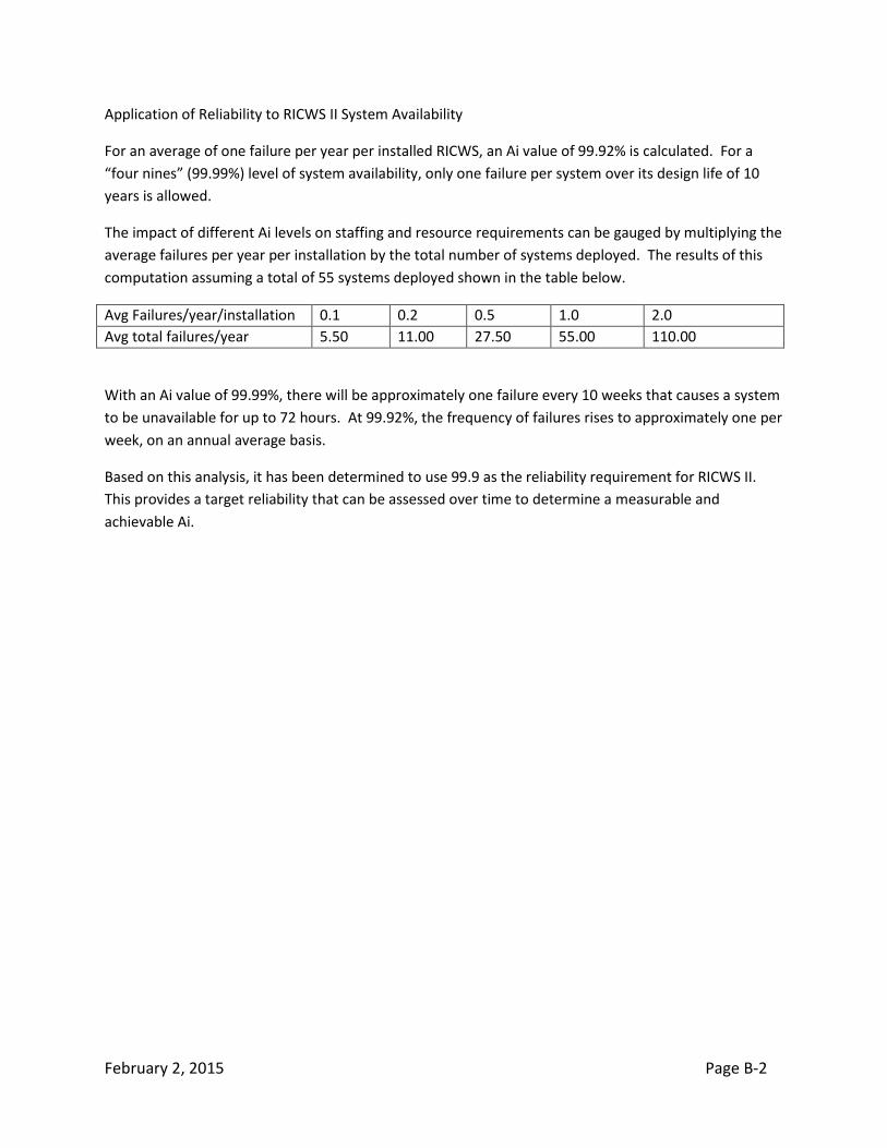
Application of Reliability to RICWS II System Availability
For an average of one failure per year per installed RICWS, an Ai value of 99.92% is calculated. For a
“four nines” (99.99%) level of system availability, only one failure per system over its design life of 10
years is allowed.
The impact of different Ai levels on staffing and resource requirements can be gauged by multiplying the
average failures per year per installation by the total number of systems deployed. The results of this
computation assuming a total of 55 systems deployed shown in the table below.
Avg Failures/year/installation 0.1 0.2 0.5 1.0 2.0
Avg total failures/year 5.50 11.00 27.50 55.00 110.00
With an Ai value of 99.99%, there will be approximately one failure every 10 weeks that causes a system
to be unavailable for up to 72 hours. At 99.92%, the frequency of failures rises to approximately one per
week, on an annual average basis.
Based on this analysis, it has been determined to use 99.9 as the reliability requirement for RICWS II.
This provides a target reliability that can be assessed over time to determine a measurable and
achievable Ai.