system products and accessories
TRANSCRIPT

System products and accessories
13
Overview and selection tools 346
System products Bus coupling units 350
Power supply units 351
Line couplers 353
Network gateways 354
© Siemens Schweiz AG

System products and accessories Overview and selection tools
346
Siemens Switzerland Ltd www.siemens.de/gamma 2019 Smart Infrastructure
13
© Siemens Schweiz AG

System products and accessories Overview and selection tools
347
Siemens Switzerland Ltd www.siemens.de/gamma 2019 Smart Infrastructure
13
© Siemens Schweiz AG
System products and accessories Overview and selection tools
348
Siemens Switzerland Ltd www.siemens.de/gamma 2019 Smart Infrastructure
13
© Siemens Schweiz AG

System products and accessories Overview and selection tools
349
Siemens Switzerland Ltd www.siemens.de/gamma 2019 Smart Infrastructure
13
© Siemens Schweiz AG

System products and accessories System products Bus coupling units
350
Siemens Switzerland Ltd www.siemens.de/gamma 2019 Smart Infrastructure
13
Bus transceiver modules, mounting depth 18 mm
For connection of a modular bus device to the bus line
10-pole BTI socket (BTI - Bus Transceiver Interface) for plugging of bus terminal devices with BTI
connector
For installation in flush-mounting switch and socket boxes with Ø 60 mm in diameter 40 mm deep
Screw fixing
Bus connection via bus terminal
Data sheet A6V10416065
Dimensions (W x H x D) 71 x 71 x 18 mm
UP 117/12
Stock no. Product no.
5WG1117-2AB12 UP 117/12
Bus Coupling Unit (BTM), NEMA
For connection of a modular bus device to the bus line
10-pole Bus Transceiver Interface (BTI) socket for clipping on an application module with BTI plug
connector, with DC converter with output voltage / current of DC 5 V / 30 mA and DC 20 V / 25 mA for
supply of the clipped on bus device via the bus line
Mounting bracket for installation in a NEMA wall box with minimum inside dimensions 50 x 89 x 40
mm (W x H x D), with screw connection
Mounting depth 19mm
Bus connection via bus terminal
Type of protection: IP 20
The matching design frame must be ordered separately. See Chapter Display and Operation Units -
Pushbutton accessories.
Data sheet A6V11808813
Dimensions (W x H x D) 111 x 65 x 19 mm
UP 117C12
Stock no. Product no.
5WG1117-2CB12 UP 117C12
© Siemens Schweiz AG
System products and accessories System products
Power supply units
351
Siemens Switzerland Ltd www.siemens.de/gamma 2019 Smart Infrastructure
13
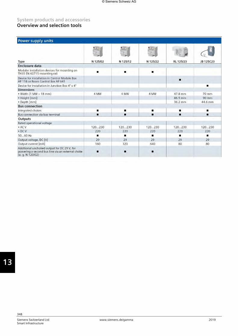
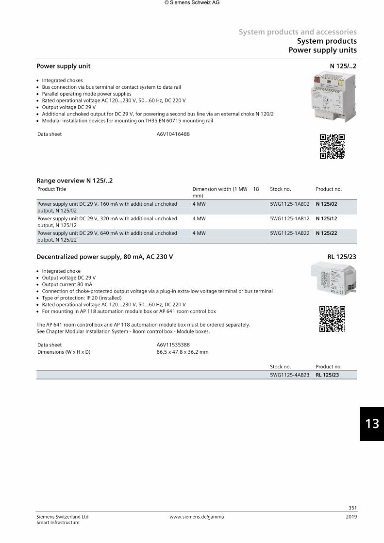
Power supply unit
Integrated chokes
Bus connection via bus terminal or contact system to data rail
Parallel operating mode power supplies
Rated operational voltage AC 120...230 V, 50...60 Hz, DC 220 V
Output voltage DC 29 V
Additional unchoked output for DC 29 V, for powering a second bus line via an external choke N 120/2
Modular installation devices for mounting on TH35 EN 60715 mounting rail
Data sheet A6V10416488
N 125/..2
Range overview N 125/..2
Product Title Dimension width (1 MW = 18
mm)
Stock no. Product no.
Power supply unit DC 29 V, 160 mA with additional unchoked
output, N 125/02
4 MW 5WG1125-1AB02 N 125/02
Power supply unit DC 29 V, 320 mA with additional unchoked
output, N 125/12
4 MW 5WG1125-1AB12 N 125/12
Power supply unit DC 29 V, 640 mA with additional unchoked
output, N 125/22
4 MW 5WG1125-1AB22 N 125/22
Decentralized power supply, 80 mA, AC 230 V
Integrated choke
Output voltage DC 29 V
Output current 80 mA
Connection of choke-protected output voltage via a plug-in extra-low voltage terminal or bus terminal
Type of protection: IP 20 (installed)
Rated operational voltage AC 120...230 V, 50...60 Hz, DC 220 V
For mounting in AP 118 automation module box or AP 641 room control box
The AP 641 room control box and AP 118 automation module box must be ordered separately.
See Chapter Modular Installation System - Room control box - Module boxes.
Data sheet A6V11535388
Dimensions (W x H x D) 86,5 x 47,8 x 36,2 mm
RL 125/23
Stock no. Product no.
5WG1125-4AB23 RL 125/23
© Siemens Schweiz AG

System products and accessories System products Power supply units
352
Siemens Switzerland Ltd www.siemens.de/gamma 2019 Smart Infrastructure
13
Decentralized Power Supply, 80 mA, AC 120 V
Integrated choke
Output voltage DC 29 V
Output current 80 mA
Connection of choke-protected output voltage via a plug-in extra-low voltage terminal or bus terminal
Type of protection: IP 20 (installed)
Rated operational voltage AC 120 V, 50...60 Hz
Built-in device with 1/2 inch thread connection for mounting to or in a UL/NEMA Junction Box with
feedthrough of the function wires through the 1/2 inch threaded connector
Data sheet A6V11808808
Dimensions (W x H x D) 70 x 90 x 44,6 mm
JB 125C23
Stock no. Product no.
5WG1125-4CB23 JB 125C23
Choke, 640 mA
For operation with a KNX power supply without integrated choke or for connection to the unchoked
output of the KNX N 125/x2 power supplies
Low-voltage terminal for unchoked voltage and bus
Modular installation devices for mounting on TH35 EN 60715 mounting rail
Data sheet A6V10416067
Dimension width (1 MW = 18 mm) 2 MW
N 120/02
Stock no. Product no.
5WG1120-1AB02 N 120/02
Electronic power supply unit, 350 mA
Max. cable length between power supply unit and weather system: 100 m
Rated operational voltage 85...265 V AC (50/60 Hz), 85...300 V DC
Rated secondary voltage 24 V DC, +5 %,
Residual ripple < 100 mV
Rated secondary current 0.35 A
Electronic overload protection
Permissible ambient operating temperature: - 20...+60 °C
Degree of protection: IP20
For mounting on EN 60715-TH35-7.5 mounting rail
Dimension width (1 MW = 18 mm) 2 MW
4AC2402
Stock no. Product no.
4AC2402 4AC2402
© Siemens Schweiz AG

System products and accessories System products
Line couplers
353
Siemens Switzerland Ltd www.siemens.de/gamma 2019 Smart Infrastructure
13
IP-Router Secure
For interconnection of bus lines or bus areas via a fast data network (Ethernet 10BaseT or 100BaseT)
with Internet Protocol (IP)
To be used as line, area and system coupler
Uses the KNXnet/IP protocol or secured access and data transmission via KNXnet/IP Secure
Up to four KNXnet/IP Tunneling connections for parallel bus access by ETS and further PC software
Assignment of the network parameters by the installer using ETS, automatically by a DHCP server in
the network
5 LEDs for display of availibility, KNX communication and IP communication
Electronics powered via “Power over Ethernet” according to IEEE 802.3af or alternatively by an
external safety extra low voltage power supply for AC/DC 24 V
Pluggable terminal block for connection of external power supply unit (not included)
Ethernet connection via RJ45 socket
Housing: plastic, color RAL 7035 (light grey), N-system
DIN rail mounted device for mounting on rail TH35 according to DIN EN 60715
Type of protection: IP 20
Data sheet A6V11656735
Dimension width (1 MW = 18 mm) 2 MW
N 146/03
Stock no. Product no.
5WG1146-1AB03 N 146/03
Accessories for N 146/03 Product Title Stock no. Product no.
Electronic power supply unit, 350 mA 4AC2402 4AC2402
LOGO! Power 24 V/1.3 A 6EP3331-6SB00-0AY0 LOGO!POWER 24 V/1,3 A
Line/backbone coupler
For data exchange between two KNX bus lines with telegrams of up to 64 byte
For use as line coupler for connecting a line to the main line or as backbone coupler for connecting a
main line to the backbone line or as repeater for connecting two segments of the same line, with
electrical isolation of the two bus lines
Loadable filter table for control of the data exchange between the two bus lines
Additional loadable filter table for telegrams with LTE addressing
Detection of a communication fault on the lower-level line and signaling to the higher-level line
3 LEDs for display of availability and receipt of a telegram per line
Power supply from the main line
Modular installation devices for mounting on TH35 EN 60715 mounting rail
With bus connection to the line and to the main line via bus terminal.
Data sheet A6V10416071
Dimension width (1 MW = 18 mm) 2 MW
N 140/13
Stock no. Product no.
5WG1140-1AB13 N 140/13
New Product
© Siemens Schweiz AG

System products and accessories System products Network gateways
354
Siemens Switzerland Ltd www.siemens.de/gamma 2019 Smart Infrastructure
13
IP Interface Secure
For communication between KNX devices and PCs or other devices with Ethernet (10BaseT or
100BaseT) interface, for remote access to an KNX installation
Uses the KNXnet/IP protocol or secured access and data transmission via KNXnet/IP Secure
Up to four KNXnet/IP Tunneling connections for parallel bus access by ETS and further PC software
Assignment of the network parameters by the installer using ETS, automatically by a DHCP server in
the network
5 LEDs for display of availibility, KNX communication and IP communication
Electronics powered via “Power over Ethernet” according to IEEE 802.3af or alternatively by an
external safety extra low voltage power supply for AC/DC 24V
Pluggable terminal block for connection of external power supply unit (not included)
Ethernet connection via RJ45 socket
Housing: plastic, color RAL 7035 (light grey), N-system
DIN rail mounted device for mounting on rail TH35 according to DIN EN 60715
Type of protection: IP 20
Data sheet A6V11689764
Dimension width (1 MW = 18 mm) 2 MW
N 148/23
Stock no. Product no.
5WG1148-1AB23 N 148/23
Accessories for N 148/23 Product Title Stock no. Product no.
Electronic power supply unit, 350 mA 4AC2402 4AC2402
LOGO! Power 24 V/1.3 A 6EP3331-6SB00-0AY0 LOGO!POWER 24 V/1,3 A
IP-Router Secure
For interconnection of bus lines or bus areas via a fast data network (Ethernet 10BaseT or 100BaseT)
with Internet Protocol (IP)
To be used as line, area and system coupler
Uses the KNXnet/IP protocol or secured access and data transmission via KNXnet/IP Secure
Up to four KNXnet/IP Tunneling connections for parallel bus access by ETS and further PC software
Assignment of the network parameters by the installer using ETS, automatically by a DHCP server in
the network
5 LEDs for display of availibility, KNX communication and IP communication
Electronics powered via “Power over Ethernet” according to IEEE 802.3af or alternatively by an
external safety extra low voltage power supply for AC/DC 24 V
Pluggable terminal block for connection of external power supply unit (not included)
Ethernet connection via RJ45 socket
Housing: plastic, color RAL 7035 (light grey), N-system
DIN rail mounted device for mounting on rail TH35 according to DIN EN 60715
Type of protection: IP 20
Data sheet A6V11656735
Dimension width (1 MW = 18 mm) 2 MW
N 146/03
Stock no. Product no.
5WG1146-1AB03 N 146/03
Accessories for N 146/03 Product Title Stock no. Product no.
Electronic power supply unit, 350 mA 4AC2402 4AC2402
LOGO! Power 24 V/1.3 A 6EP3331-6SB00-0AY0 LOGO!POWER 24 V/1,3 A
New Product New Product
© Siemens Schweiz AG

System products and accessories System products
Network gateways
355
Siemens Switzerland Ltd www.siemens.de/gamma 2019 Smart Infrastructure
13
IP Control Center
Visualisation controller for full-graphic visualizations on web-compatible end devices such as PCs, tablets
and smart phones with a standard web browser.
For communication between KNX devices and PCs and, in connection with a LAN-/WLAN modem or DSL
router, for remote access to a KNX installation, for usage as an interface for the ETS 3/4/5 and as an
interface for a visualization, with usage of the KNXnet/IP protocol, with the following simultaneously
usable functions:
Web server for operating and monitoring up to 1250 statuses and values transmitted by the KNX
network, which can be displayed using a standard browser on PCs, tablets, or smartphones connected
to the IP network
Special web page for firmware upgrade
Graphical web editor for a creation of fully graphical visualization with control and display elements,
configurable in various styles
Smart editor for the creation of a visualisation, tuned for mobile browsers, smartphones, tablets with
control and display elements, configurable in various styles and layouts
Annual timer, with astronomical calendar, for 300 time switch schedules with up to 30 time switch
commands per time switch schedule
Scene module with up to 5000 scenes or events
Chart module for recording and reporting of up to 10 data points
Monitoring module for monitoring and storage of up to 1000 events into a ring buffer
IP interface for control of up to 20 IP-devices via up to 20 TCP/UDP commands per IP-device
Fully graphical logic module with up to 1000 logic functions
Alarm function for up to 250 different alarms
E-mail function, with up to 20 contacts, for transmission of chart data from chart module, logged data
from monitoring module or alarm data
Ethernet interface 10/100 Mbits/s with RJ45 socket for connection to the IP network using the Internet
Protocol
2 LED displays for IP connection/communication and for error messages
Integrated bus connector and bus terminal for connection to a KNX network
Power supply of the electronics by an external voltage source for DC 24 V, 50 mA
Series installation device for mounting on support rails TH35 DIN EN 60715
Data sheet A6V10417875
Dimension width (1 MW = 18 mm) 4 MW
N 152/01
Stock no. Product no.
5WG1152-1AB01 N 152/01
Accessories for N 152/01 Product Title Stock no. Product no.
Electronic power supply unit, 350 mA 4AC2402 4AC2402
LOGO! Power 24 V/1.3 A 6EP3331-6SB00-0AY0 LOGO!POWER 24 V/1,3 A
© Siemens Schweiz AG

System products and accessories System products Network gateways
356
Siemens Switzerland Ltd www.siemens.de/gamma 2019 Smart Infrastructure
13
IP Gateway KNX/BACnet
BACnet Application Specific Controller (B-ASC) as Gateway between KNX TP and BACnet IP
BTL certified
Up to 250 BACnet objects
Up to 455 BACnet COV subscriptions
Automatic translation of KNX communication objects into BACnet objects according to the
configuration with ETS
For communication between KNX EIB devices and PCs or other devices with Ethernet (10BaseT)
interface, as well as in conjunction with a LAN modem or DSL router for remote access to an KNX EIB
installation
For use as an interface e.g. for ETS3 or for visualization software
Use the KNXnet/IP protocol
KNXnet/IP Tunneling connection for parallel bus access by ETS and further PC software
ObjectServer connection for visualization via network connections with long signal transmission
duration
Assignment of the network parameters by the installer using ETS, or automatically by a DHCP server in
the network
2 LEDs for display of operational availability and IP communication
Additional power supply by an external safety extra low voltage power supply for AC/DC 24 V, 40 mA
Pluggable terminal block for connection of external power supply unit (not included)
Integrated bus coupling unit with bus connection via bus terminal
Ethernet connection via RJ45 socket
Mounting on DIN rail EN 60715-TH35-7.5
Data sheet A6V10466141
Dimension width (1 MW = 18 mm) 4 MW
N 143/01
Stock no. Product no.
5WG1143-1AB01 N 143/01
Accessories for N 143/01
Product Title Stock no. Product no.
Electronic power supply unit, 350 mA 4AC2402 4AC2402
LOGO! Power 24 V/1.3 A 6EP3331-6SB00-0AY0 LOGO!POWER 24 V/1,3 A
Bus terminal, 2-pole, 4 plug-in connectors, red/dark gray
For connection of bus devices to the bus cable
For connection of up to 4 bus cables
Comprising two engaged clamp parts + (red) and - (dark gray), each with 4 screwless plug-in terminals
per clamp part for solid conductors, ∅ 0.6 mm...0.8 mm
Dimensions (W x H x D) 10 x 12.4 x 10 mm
S 193/01
Stock no. Product no.
5WG1193-8AB01 S 193/01
© Siemens Schweiz AG

System products and accessories System products
Network gateways
357
Siemens Switzerland Ltd www.siemens.de/gamma 2019 Smart Infrastructure
13
Overvoltage protection, as fine protection for bus devices
For the overvoltage fine protection of bus devices
For inserting in a bus device instead of a 193 bus terminal or for direct connection to a bus terminal
For surge protection through connection of the yellow/green ground conductor to the next grounding
point
2 socket contacts (1 mm ∅) for insertion in bus devices
2 solid wires (0.8 mm ∅) for connection to the bus terminal
A solid wire (0.75 mm ∅) for surge protection
Rated voltage DC 24 V
Rated current 6 A
Rated discharge surge current 5 kA
Protection level 350 V
Data sheet A6V10416502
Dimensions (W x H x D) 11.6 x 10.5 x 11.1 mm
S 190/01
Stock no. Product no.
5WG1190-8AD01 S 190/01
© Siemens Schweiz AG