system-manual id cpr50-family...obid® classic-pro manual id cpr50.10-xe / id max50.10-xe feig...
TRANSCRIPT

MANUAL
final
public (B)
2012-03-27
H90201-4e-ID-B.docx
ID CPR50.10-xE
ID MAX50.10-xE RFID Reader for ISO/IEC14443-A & -B, NFC and ISO/IEC15693
with Ethernet Interface for
Access Control and General-Purpose Applications
Up From Firmware Version 02.00.00

OBID® classic-pro Manual ID CPR50.10-xE / ID MAX50.10-xE
FEIG ELECTRONIC GmbH Page 2 of 183 H90201-4e-ID-B.docx
Note
Copyright 2012 by
FEIG ELECTRONIC GmbH
Lange Strasse 4
D-35781 Weilburg-Waldhausen (Germany)
Tel.: +49 6471 3109-0
http://www.feig.de
With the edition of this manual, all previous editions become void. Indications made in this manual may be changed with-
out previous notice.
Copying of this document, and giving it to others and the use or communication of the contents thereof are forbidden with-
out express authority. Offenders are liable to the payment of damages. All rights are reserved in the event of the grant of a
patent or the registration of a utility model or design.
Composition of the information in this manual has been done to the best of our knowledge. FEIG ELECTRONIC GmbH
does not guarantee the correctness and completeness of the details given in this manual and may not be held liable for
damages ensuing from incorrect or incomplete information. Since, despite all our efforts, errors may not be completely
avoided, we are always grateful for your useful tips.
The installation instructions given in this manual are based on advantageous boundary conditions. FEIG ELECTRONIC
GmbH does not give any guarantee promise for perfect function in cross environments.
FEIG ELECTRONIC GmbH assumes no responsibility for the use of any information contained in this manual and makes
no representation that they free of patent infringement. FEIG ELECTRONIC GmbH does not convey any license under its
patent rights nor the rights of others.
Copyright pertaining to TCP / IP Stack: Copyright (c) 2001-2006, Adam Dunkels and the Swedish Institute of Computer
Science- All rights reserved. Redistribution and use in source and binary forms, with or without modification, are permitted
provided that the following conditions are met:
1. Redistributions of source code must retain the above copyright notice, this list of conditions and the following disclaim-
er.
2. Redistributions in binary form must reproduce the above copyright notice, this list of conditions and the following dis-
claimer in the documentation and/or other materials provided with the distribution.
3. The name of the author may not be used to endorse or promote products derived from this software without specific
prior written permission.
THIS SOFTWARE IS PROVIDED BY THE AUTHOR `AS IS' AND ANY EXPRESS OR IMPLIED WARRANTIES,
INCLUDING, BUT NOT LIMITED TO, THE IMPLIED WARRANTIES OF MERCHANTABILITY AND FITNESS FOR A
PARTICULAR PURPOSE ARE DISCLAIMED. IN NO EVENT SHALL THE AUTHOR BE LIABLE FOR ANY DIRECT,
INDIRECT, INCIDENTAL, SPECIAL, EXEMPLARY, OR CONSEQUENTIAL DAMAGES (INCLUDING, BUT NOT LIMITED
TO, PROCUREMENT OF SUBSTITUTE GOODS OR SERVICES; LOSS OF USE, DATA, OR PROFITS; OR BUSINESS
INTERRUPTION) HOWEVER CAUSED AND ON ANY THEORY OF LIABILITY, WHETHER IN CONTRACT, STRICT
LIABILITY, OR TORT (INCLUDING NEGLIGENCE OR OTHERWISE) ARISING IN ANY WAY OUT OF THE USE OF THIS
SOFTWARE, EVEN IF ADVISED OF THE POSSIBILITY OF SUCH DAMAGE.
OBID® and OBID i-scan
® is a registered trademark of FEIG ELECTRONIC GmbH.
All cited brand names, product names, or trademarks belong to their respective holders.

OBID® classic-pro Manual ID CPR50.10-xE / ID MAX50.10-xE
FEIG ELECTRONIC GmbH Page 3 of 183 H90201-4e-ID-B.docx
General information's regarding this manual
If bits within one byte are filled with "-", these bit spaces are reserved for future extensions or for internal
testing- and manufacturing-functions. These bit spaces must not be changed, as this may cause faulty op-
eration of the Reader.
The following figure formats are used:
0...9: for decimal figures
0x00...0xFF: for hexadecimal figures
b0...1 for binary figures.
The hexadecimal value in brackets "[ ]" indicates a command.
OBID® classic-pro Manual ID CPR50.10-xE / ID MAX50.10-xE
FEIG ELECTRONIC GmbH Page 4 of 183 H90201-4e-ID-B.docx
Content
Revision History of this documentation 9
Abbreviations ......................................................................................................................... 10
1. Introduction 11
1.1. ID CPR50.10-xE ................................................................................................................ 11
1.2. ID MAX50.10-xE ............................................................................................................... 12
2. Data Transmission between OBID® ID CPR-Reader and Host 13
2.1. Configuration and Control Commands .......................................................................... 13
2.2. ISO Host Commands ....................................................................................................... 14
2.3. Notification Mode ............................................................................................................ 16
2.4. Interface data encryption ................................................................................................ 17
2.5. Data Format and Protocol Frames for bi-directional communication ......................... 18
2.5.1. Standard Protocol Frame (up to 255 Byte) ................................................................. 19
2.5.2. Advanced Protocol Frame.......................................................................................... 19
2.5.3. Protocol Elements ...................................................................................................... 20
2.5.4. Timing Conditions ...................................................................................................... 21
2.5.5. CRC16 Calculation Algorithm for Protocol Frames .................................................... 21
2.6. Characteristics of TCP/IP protocol ................................................................................ 22
3. Configuration Parameters (CFG) 23
3.1. CFG0: Crypto ................................................................................................................... 25
3.2. CFG1: Interface ............................................................................................................... 26
3.3. CFG2: Inputs / Outputs general ..................................................................................... 28
3.4. CFG3: RF-Interface .......................................................................................................... 31
3.5. CFG4: Transponder Parameters .................................................................................... 35
3.6. CFG5: Anticollision ......................................................................................................... 37
3.7. CFG6 .. 10: Reserved ...................................................................................................... 38
3.8. CFG11: Read Mode – Read Data 1 ................................................................................. 38
3.9. CFG12: Read Mode - Filter .............................................................................................. 40
3.10. CFG13 .. 14: Reserved ................................................................................................... 40
3.11. CFG15: Read Mode – Read Data 2 ............................................................................... 41
3.12. CFG16: Persistence Reset ............................................................................................ 43
OBID® classic-pro Manual ID CPR50.10-xE / ID MAX50.10-xE
FEIG ELECTRONIC GmbH Page 5 of 183 H90201-4e-ID-B.docx
3.13. CFG17 .. 19: Reserved ................................................................................................... 43
3.14. CFG40: LAN Settings, Part 1 ........................................................................................ 44
3.15. CFG41: LAN Settings, Part 2 ........................................................................................ 45
3.16. CFG49: Notification Channel ........................................................................................ 47
4. Commands for Reader Configuration 48
4.1. [0x80] Read Configuration .............................................................................................. 48
4.2. [0x81] Write Configuration .............................................................................................. 49
4.3. [0x82] Save Configuration .............................................................................................. 50
4.4. [0x83] Set Default Configuration .................................................................................... 51
4.5. [0xA2] Write Mifare Reader Keys.................................................................................... 52
4.6. [0xA3] Write DES/AES Reader Keys ............................................................................... 53
4.7. [0xAD] Write Reader Authent-Key .................................................................................. 55
5. Commands for Reader Control 56
5.1. [0x63] CPU Reset ............................................................................................................. 56
5.2. [0x64] System Reset........................................................................................................ 56
5.3. [0x65] Get Software Version ........................................................................................... 57
5.4. [0x66] Get Reader Info .................................................................................................... 59
5.4.1. Mode = 0x00 (RF Controller Firmware) ...................................................................... 60
5.4.2. Mode = 0x03 (RF-decoder information's) ................................................................... 60
5.4.3. Mode = 0x04 (Additional firmware functionality) ......................................................... 61
5.4.4. Mode = 0x05 (Bootloader version information) ........................................................... 62
5.4.6. Mode = 0x07 (CPRIO information) ............................................................................. 63
5.4.7. Mode = 0x10 (Hardware information) ......................................................................... 64
5.4.9. Mode = 0x50 (MAC-address) ..................................................................................... 66
5.4.10. Mode = 0x80 (Device_ID) ........................................................................................ 67
5.4.11. Mode = 0xFF (All Info Records) ............................................................................... 68
5.5. [0x69] RF Reset ............................................................................................................... 69
5.6. [0x6A] RF Output ON/OFF .............................................................................................. 70
5.7. [0x72] Set Output............................................................................................................ 71
5.7.1. Set Output Examples ................................................................................................. 73
5.8. [0x74] Get Input ............................................................................................................... 74
5.9. [0xAE] Reader Authent .................................................................................................... 75
6. ISO Host Commands for Transponder Communication 76
OBID® classic-pro Manual ID CPR50.10-xE / ID MAX50.10-xE
FEIG ELECTRONIC GmbH Page 6 of 183 H90201-4e-ID-B.docx
6.1. [0xB0] ISO Standard Host Commands ........................................................................... 76
6.1.1. [0x01] Inventory ......................................................................................................... 77
6.1.1.1. Response-Data - ISO 14443A (TR-TYPE = 0x04) ......................................... 78
6.1.1.2. Response-Data - ISO 14443B (TR-TYPE = 0x05) ......................................... 80
6.1.1.3. Response-Data - ISO 15693 (TR-TYPE = 0x03) ........................................... 81
6.1.1.5. Sequences of Inventory Command and ISO14443 Transponder ................... 82
6.1.2. [0x25] Select .............................................................................................................. 83
6.1.3. [0x23] Read Multiple Blocks ....................................................................................... 87
6.1.4. [0x24] Write Multiple Blocks ....................................................................................... 89
6.2. [0xB0] ISO 15693 Mandatory and Optional Host Commands ....................................... 91
6.2.1. [0x02] Stay Quiet ....................................................................................................... 91
6.2.2. [0x22] Lock Multiple Blocks ........................................................................................ 92
6.2.3. [0x29] Write DSFI ...................................................................................................... 93
6.2.4. [0x26] Reset to Ready ............................................................................................... 94
6.2.5. [0x27] Write AFI ......................................................................................................... 95
6.2.6. [0x28] Lock AFI .......................................................................................................... 96
6.2.7. [0x2A] Lock DSFI ....................................................................................................... 97
6.2.8. [0x2B] Get System Information .................................................................................. 98
6.2.9. [0x2C] Get Multiple Block Security Status ................................................................ 100
6.3. [0xB0] ISO 14443 Standard Host Commands .............................................................. 101
6.3.1. [0xC0] Halt ............................................................................................................... 101
6.4. [0xB2] ISO14443 Special Host Commands .................................................................. 102
6.4.1. [0x30] Mifare Value Commands ............................................................................... 103
6.4.2. [0xB0] Authent Mifare .............................................................................................. 105
6.4.3. [0xB2] Authent Mifare Ultralight C ............................................................................ 107
6.4.4. [0xBE] ISO 14443-4 T=CL (#) .................................................................................. 108
6.4.5. [0xBF] ISO 14443-4 Container Command (#) .......................................................... 114
6.4.6. [0x2B] ISO14443-4 Transponder-Info ...................................................................... 116
6.5. [0xC1] / [0xC3] ISO Host Commands for mifare DESFire Communication .............. 117
6.6. [0xC2] ISO Host Commands for mifare Plus Communication .................................. 117
6.7. Special Commands for Transponder Communication ............................................... 118
6.7.1. [0xBD] ISO14443A Transparent Command ............................................................. 118
6.7.2. [0xBE] ISO14443B Transparent Command ............................................................. 123
7. Commands for Notification Mode 128
7.1. The Notification Mode Procedure ................................................................................ 128
7.2. [0x22] Read Buffer ......................................................................................................... 129
7.3. [0x31] Read Data Buffer Info ........................................................................................ 131
7.4. [0x32] Clear Data Buffer ................................................................................................ 131
7.5. [0x33] Initialize Buffer ................................................................................................... 132
OBID® classic-pro Manual ID CPR50.10-xE / ID MAX50.10-xE
FEIG ELECTRONIC GmbH Page 7 of 183 H90201-4e-ID-B.docx
8. Access Mode (ID MAX50.10-xE only) 133
8.1. The Access Data Structure ........................................................................................... 133
8.1.1. CRC List .................................................................................................................. 133
8.1.2. Metadata .................................................................................................................. 133
8.1.3. Timezone Table ....................................................................................................... 134
8.1.4. Holiday Table ........................................................................................................... 137
8.1.5. Access Table ........................................................................................................... 137
8.1.6. Event Table.............................................................................................................. 138
8.2. The Access Mode Procedure ........................................................................................ 139
8.3. [0x01] MAX Data Exchange Protocol ........................................................................... 140
8.3.1. [0x01] StartUpdate ................................................................................................... 142
8.3.2. [0x02] EndUpdate .................................................................................................... 144
8.3.3. [0x03] Write Table ................................................................................................... 145
8.3.4. [0x05] Read Table ................................................................................................... 146
8.3.5. [0x06] Notify Event ................................................................................................... 150
8.4. Additional Configuration Parameters (CFG) ............................................................... 151
8.4.1. CFG1: Interface ....................................................................................................... 151
8.4.2. CFG11: Read Mode – Read Data 1 ......................................................................... 152
8.4.3. CFG14: Access Control ........................................................................................... 154
8.4.4. CFG47: Network Time Protocol ............................................................................... 158
8.5. Additional Commands for Reader Configuration ........................................................ 162
8.5.1. [0x87] Set System Time and Date ........................................................................... 162
8.5.2. [0x88] Get System Time and Date ........................................................................... 163
8.6. Additional Commands for Reader Control .................................................................. 164
8.6.1. [0x66] Get Reader Info Mode = 0x04 (Additional firmware functionality) .................. 164
8.6.2. [0x6E] Reader Diagnostic Mode = 0x06 (MAX Status) ............................................. 166
9. Supported ISO Host commands 167
9.1. ISO14443-A & -B Part 4 compatible Transponder ....................................................... 167
9.1.1. Common Processorcards ........................................................................................ 167
9.1.2. NXP - mifare DESFire .............................................................................................. 168
9.1.3. NXP - mifare Plus (Security Level 3) ........................................................................ 170
9.2. ISO14443-A Part 3 compatible Transponder ............................................................... 172
9.2.1. Infineon - my-d move SLE66R01P ........................................................................... 172
9.2.2. NXP - Mifare classic: mini, 1k, 4k / mifare plus (Level 1) ......................................... 173
9.2.3. NXP - Mifare Ultralight ............................................................................................. 174
9.2.4. NXP - Mifare Ultralight C .......................................................................................... 175
ANNEX 176
ANNEX A: Codes of Transponder Types ............................................................................ 176
ANNEX B: Codes of Reader Types ...................................................................................... 177

OBID® classic-pro Manual ID CPR50.10-xE / ID MAX50.10-xE
FEIG ELECTRONIC GmbH Page 8 of 183 H90201-4e-ID-B.docx
ANNEX C: Index of Status Bytes ......................................................................................... 178
ANNEX C1: ISO15693-Error, Error-Codes ........................................................................ 180
ANNEX C2: ISO14443-Error, Error-Codes ........................................................................ 181
ANNEX C3: Crypto Processing Error - ERROR-CODE...................................................... 182
ANNEX D: Examples for Read Data .................................................................................... 183
ISO-Host Command (DB-Size of the Transponder = 4Byte) .............................................. 183
ISO-Host Command (DB-Size of the Transponder = 8Byte) .............................................. 183

OBID® classic-pro Manual ID CPR50.10-xE / ID MAX50.10-xE
FEIG ELECTRONIC GmbH Page 9 of 183 H90201-4e-ID-B.docx
Revision History of this documentation
Revision Description
0 Described Firmware: 01.00.00
Preliminary Version - Changes are not separate recorded.
1
Described Firmware: 01.01.00
Parameter CFG11.D-OFFSET and CFG11.D-LENGTH added (Access Mode only).
Parameter CFG14.ACCESS-MODE added (Access Mode only).
Parameter CFG14.ACCESS-STATE, CFG14.ACCESS-ACTIVATIOn-TIME, CFG14.ACCESS-
DENIED-STATE and CFG14.ACCESS-DENIED-ACTIVATIOn-TIME redefined (Access Mode only).
Chapters “ISO Host Commands for mifare DESFire Communication [0xC1]” and “ ISO Host
Commands for mifare Plus Communication [0xC2]” added.
2
Described Firmware: 01.06.00
Chapter "Interface data encryption" added.
Command [0xAD] Write Reader Authent-Key added.
Command [0xAE] Reader Authent added.
3
Described Firmware: 01.07.00
Parameter CFG47: Network Time Protocol added (Access Mode only).
Command [0x66] Get Reader Info - Mode = 0x04 (Additional firmware functionality) added.
4
Described Firmware: 02.00.00
Parameter CFG11.TR-Data-1.Extention and CFG11.TR-Data-2 added.
Parameter CFG41.LAN-OPTIONS.SPEED added.
Default parameters corrected for CFG1.TR.RESPONSE-TIME, CFG3.ISO14443 BIT RATE,
CFG41.LAN-OPTIONS.
Command [0x66] Get Reader Info - Mode = 0xFF (All info records) added.
Chapter “ISO Host Commands for Transponder Communication” updated.
Chapter "[0xB0] ISO 15693 Mandatory and Optional Host Commands" added.
Description of SoftCrypto functions for mifare DESFire, mifare Ultralight C and mifare PLUS trans-
ferred to separate manual H01110-#e-ID-B.doc (Commands [0xC1] and [0xC2] are not longer docu-
mented in this manual).
Chapters "[0xC1] / [0xC3] ISO Host Commands for mifare DESFire Communication" and "[0xC2] ISO
Host Commands for mifare Plus Communication" added.
Parameter TR_INFO, TR-Data2 and MAC-Addess in chapter 7.2. [0x22] Read Buffer added.
Chapters 9.1.2. NXP - mifare DESFire and 9.1.3. NXP - mifare Plus (Security Level 3) updated.
ANNEX B: Codes of Reader Types and ANNEX C: Index of Status Bytes updated.
OBID® classic-pro Manual ID CPR50.10-xE / ID MAX50.10-xE
FEIG ELECTRONIC GmbH Page 10 of 183 H90201-4e-ID-B.docx
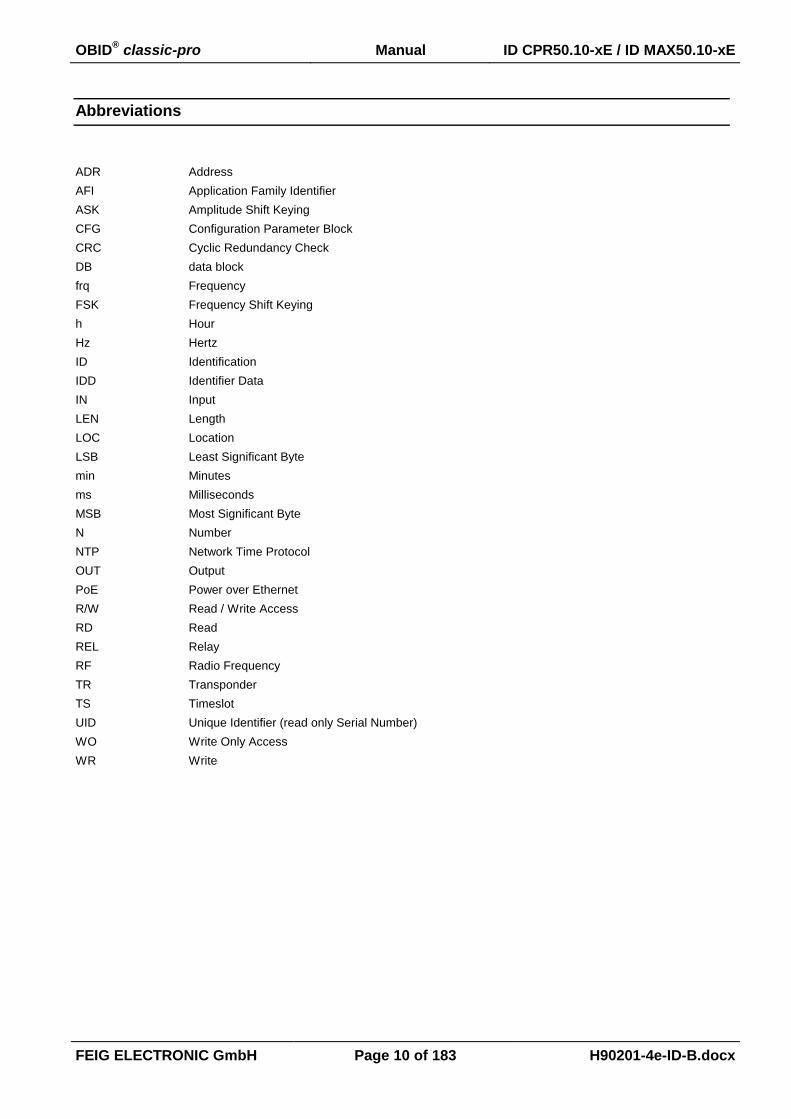
Abbreviations
ADR Address
AFI Application Family Identifier
ASK Amplitude Shift Keying
CFG Configuration Parameter Block
CRC Cyclic Redundancy Check
DB data block
frq Frequency
FSK Frequency Shift Keying
h Hour
Hz Hertz
ID Identification
IDD Identifier Data
IN Input
LEN Length
LOC Location
LSB Least Significant Byte
min Minutes
ms Milliseconds
MSB Most Significant Byte
N Number
NTP Network Time Protocol
OUT Output
PoE Power over Ethernet
R/W Read / Write Access
RD Read
REL Relay
RF Radio Frequency
TR Transponder
TS Timeslot
UID Unique Identifier (read only Serial Number)
WO Write Only Access
WR Write
OBID® classic-pro Manual ID CPR50.10-xE / ID MAX50.10-xE
FEIG ELECTRONIC GmbH Page 11 of 183 H90201-4e-ID-B.docx
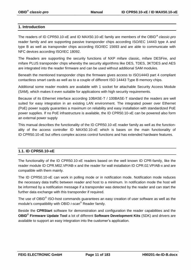
1. Introduction
The readers of ID CPR50.10-xE and ID MAX50.10-xE family are members of the OBID classic-pro
reader family and are supporting passive transponder chips according ISO/IEC 14443 type A and
type B as well as transponder chips according ISO/IEC 15693 and are able to communicate with
NFC devices according ISO/IEC 18092.
The Readers are supporting the security functions of NXP mifare classic, mifare DESFire, and
mifare PLUS transponder chips whereby the security algorithms like DES, TDES, 3KTDES and AES
are integrated into the reader firmware and can be used without additional SAM modules.
Beneath the mentioned transponder chips the firmware gives access to ISO14443 part 4 compliant
contactless smart cards as well as to a couple of different ISO 14443 Type B memory chips.
Additional some reader models are available with 1 socket for attachable Security Access Module
(SAM), which makes it even suitable for applications with high security requirements.
Because of its Ethernet interface according 10BASE-T / 100BASE-T standard the readers are well
suited for easy integration in an existing LAN environment. The integrated power over Ethernet
(PoE) power supply guaranties a maximum on reliability and easy installation with standardized PoE
power supplies. If no PoE infrastructure is available, the ID CPR50.10-xE can be powered also form
an external power supply
This manual describes the functionality of the ID CPR50.10-xE reader family as well as the function-
ality of the access controller ID MAX50.10-xE which is bases on the main functionality of
ID CPR50.10-xE but offers complex access control functions and has extended hardware features.
1.1. ID CPR50.10-xE
The functionality of the ID CPR50.10-xE readers based on the well known ID CPR-family, like the
reader module ID CPR.M02.VP/AB-x and the reader for wall installation ID CPR.02.VP/AB-x and are
compatible with them mainly.
The ID CPR50.10-xE can work in polling mode or in notification mode. Notification mode reduces
the necessary data traffic between reader and host to a minimum. In notification mode the host will
be informed by a notification message if a transponder was detected by the reader and can start the
further data exchange with this transponder if required.
The use of OBID® ISO-host commands guarantees an easy creation of user software as well as the
module's compatibility with OBID i-scan® Reader family.
Beside the CPRStart software for demonstration and configuration the reader capabilities and the
OBID® Firmware Update Tool a lot of different Software Development Kits (SDK) and drivers are
available to support an easy integration into the customer’s application.

OBID® classic-pro Manual ID CPR50.10-xE / ID MAX50.10-xE
FEIG ELECTRONIC GmbH Page 12 of 183 H90201-4e-ID-B.docx
1.2. ID MAX50.10-xE
The ID MAX50.10-xE based upon the ID CPR50.10-xE but has additional functionality which gives
the device the ability of a complete stand alone access controller which can decide offline and with-
out a permanent connected host computer about the permission of presented Transponders.
Therefore the MAX50.10-xE hardware is equipped with a non non-volatile storage to store a large
number of permitted access data sets and can handle a configurable number of logging records.
Further the hardware is equipped with a power fail buffered real-time clock to supply the possibility
of user individual time restricted access.
A power fail buffered real-time clock guarantees the possibility of individual time restricted access.
ID MAX50.10-xE offers 15 time zones and the possibility to define additional holidays which are
handled like Sundays. Each access entry can be connected to various timezones which guarantees
a flexible time limitation concept for each user.
The following table gives an overview about the possible number of Access Entries (Users) that can
be handled by MAX50.10-xE together with 10 Timezones Entries and 40 Holiday Entries depending
on the data length of user data (Identifier Data: IDD) which shall be checked.
IDD length Number of Access Entries max. number of buffered Events
16 Byte
1000 1651 Events
2000 972 Events
3300 90 Events
7 Byte
1000 1972 Events
3000 1258 Events
5000 543 Events
6300 79 Events
4 Byte
1000 2079 Events
3000 1579 Events
5000 1079 Events
7000 579 Events
9000 79 Events
To identify a user MAX50.10-xE can either read the UID or a configurable data segment of the pre-
sented Transponder. The configuration of the data which shall be evaluated to decide about the
permission of the presented Transponder can be configured in the notification mode settings of
MAX50.10-xE.

OBID® classic-pro Manual ID CPR50.10-xE / ID MAX50.10-xE
FEIG ELECTRONIC GmbH Page 13 of 183 H90201-4e-ID-B.docx
2. Data Transmission between OBID® ID CPR-Reader and Host
Different ways of data transmission between OBID® classic-pro Readers and host (terminal, PC) are
possible. The ISO Host Commands and the Notification-Mode are used for the data exchange be-
tween Transponder and host, whereas the Configuration and Control Commands are for adapting
the Reader parameters to the individual requirements of the applications.
2.1. Configuration and Control Commands
This method of data transmission is used for Reader configuration and diagnostics.
The Reader-configuration parameters will be stored in the Reader memory. To store the current
configuration during a power down of the Reader the Reader configuration has to be stored in the
EEPROM. After the Reader was powered up the configuration out of the EEPROM is used.
Host (Terminal / PC / ....) Reader
parameter- / control command parameter received and stored / control
command processed
yes no
status /
data
error status

OBID® classic-pro Manual ID CPR50.10-xE / ID MAX50.10-xE
FEIG ELECTRONIC GmbH Page 14 of 183 H90201-4e-ID-B.docx
2.2. ISO Host Commands
The ISO Host Commands provide the exchange of data between a host and Transponders via the
Reader as long as the Transponder remains in the detection range of the Reader.
NOTICE:
During the writing of data on a Transponder, it must be ensured that the Transponder is lo-
cated within the detection range of the Reader during the entire process. If the Transponder
is removed from detection range of the Reader during a writing process, this will cause a
loss of data.
The Reader distinguishes between the following different addressing modes:
Addressed mode:
Before reading or writing data in addressed mode, the UID of the Transponder has to be
known. This is executed by sending the command “6.1.1. [0x01] Inventory“. If a Transpond-
er is located within the detection range of the Reader at that time, it answers with its UID.
For all following read- / write orders the Transponder must be addressed with its correct
UID.
The following chart will show the necessary steps for the communication with a Transpond-
er in addressed mode:
Host (Terminal / PC / ....) Reader
Inventory
to get the UID
Transponder in antenna field?
Yes No
status /
number of Tran-
sponders / UID
status =
no Transponder
read data from Transponder with UID Transponder with
correct UID in antenna field?
Yes No
status /
Transponder read
data
status =
no Transponder
in Reader field
write data to Transponder with UID Transponder with
correct UID in antenna field?
Yes No
OK status status =
no Transponder
in Reader field

OBID® classic-pro Manual ID CPR50.10-xE / ID MAX50.10-xE
FEIG ELECTRONIC GmbH Page 15 of 183 H90201-4e-ID-B.docx
Selected:
In this mode the Reader communicates only with the one, selected Transponder.
Before reading or writing data in selected mode, the UID of the Transponder has to be
known. This is executed by sending at first the protocol “6.1.1. [0x01] Inventory“. In a se-
cond step the Transponder must be selected with the select command (see: 6.1.2. [0x25]
Select) which must include its UID.
The following chart will show the necessary steps for the communication with a Transpond-
er in selected mode:
Host (Terminal / PC / ....) Reader
Inventory
to get the UID
Transponder in antenna field?
Yes No
status /
number of Tran-
sponders / UID
status =
no Transponder
select Transponder with UID Transponder with the
correct UID in antenna field?
Yes No
status /
Transponder read
data
status =
no Transponder
in Reader field
read data Selected Transponder in antenna field?
Yes No
status /
Transponder read
data
status =
no Transponder
in Reader field
write data Selected Transponder in antenna field?
Yes No
OK status status =
no Transponder
in Reader field

OBID® classic-pro Manual ID CPR50.10-xE / ID MAX50.10-xE
FEIG ELECTRONIC GmbH Page 16 of 183 H90201-4e-ID-B.docx
2.3. Notification Mode
In notification mode the reader self initiated reads predefined data from Transponders which get
inside the antenna field and transmits a notification message to the host if a transponder was de-
tected by the reader. Notification mode is also the base function for data reading for the access
mode of MAX50.10-xE.
After power up or a 5.1. [0x63] CPU Reset command the notification mode starts with transponder
reading according its configuration (see 3.8. CFG11: Read Mode – Read Data 1, 3.9. CFG12: Read
Mode - Filter and 3.11. CFG15: Read Mode – Read Data 2). The notification mode can be config-
ured to read the card serial number (UID) and data elements (Data) from a Transponder memory.
Depending on the Transponder type the following options are supported.
UID:
The UID can be read form each ISO15693 and ISO14443-3 type A or type B compliant
Transponder.
Data:
Data elements can be read from the Transponders listed in the following table
Transponder Type Data
ISO15693
mifare classic
mifare PLUS (SL1)
NFC Tag Type 2
mifare Ultralight
mifare Ultralight C (plain and secured1)
my-d move (plain)
mifare DESFire on request
mifare PLUS (SL3) on request
... further transponder driver on request
Queued Transponder data and optionally Input/Status events are notified automatically and asyn-
chronously to a host with the 7.2. [0x22] Read Buffer response command. The destination address
and the notification conditions can be set in 3.16. CFG49: Notification Channel configuration block.
In general, the notification channel can be used simultaneously with the host interface.
A notification is normally not acknowledged by the host. Thus the deletion of the transferred data
with the 7.4. [0x32] Clear Data Buffer command is not necessary. As an option, this acknowledge-
ment can be enabled to synchronize the notifications with the host to prevent notification overflow in
the host application.
1 Data block addresses above 0x0F are always accessed as secured memory.

OBID® classic-pro Manual ID CPR50.10-xE / ID MAX50.10-xE
FEIG ELECTRONIC GmbH Page 17 of 183 H90201-4e-ID-B.docx
The notification message format depends on settings for the read mode in 3.8. CFG11: Read Mode
– Read Data and 3.9. CFG12: Read Mode - Filter as well as settings for the notification trigger in
3.16. CFG49: Notification Channel.
An additional option of the Notification Mode is the Keepalive message, which can be sent periodi-
cally to the host. The Keepalive message transports valuable information about the reader hard-
ware. Keepalive messages are always never acknowledged by the host. The Keepalive message
should not be mistaken with the keepalive option (s. CFG41/CFG43) of a LAN-Connection initiated
by a host.
2.4. Interface data encryption
The ID CPR50.10-xE / ID MAX50.10-xE readers can secure the data transmission over Ethernet
(TCP/IP) with the 128 / 192 / 256 bit AES algorithm. The Authentication Key (Password) is stored in
the Reader and cannot read back. The crypto mode is disabled by default.
The encrypted data transmission will be enabled by activating the crypto mode in the Reader con-
figuration with a following CPU-Reset. After that, the Reader accepts only enciphered protocols. To
get access rights in crypto mode, the first command must be an authentication command 5.9.
[0xAE] Reader Authent, transporting the enciphered password (password contains only nulls by de-
fault), to open a new session. Every successive protocol will then enciphered automatically. After the
first authentication a new password should be saved in the Reader and a new authentication with
the new password should be executed. This procedure – to switch into the crypto mode first and to
change the password secondly – ensures that the new password will be transmitted enciphered!
Otherwise the new password will be transmitted plain.
Notes:
- A Reader with activated crypto mode ignores all plain protocols and returns the status
0x19 (Crypto Processing Error).
- A Reader in plain mode ignores all enciphered protocols and returns the status 0x82
(Command not available). An authentication into the Reader with a false password will be
returned with status 0x12 (Authent Error).
- A Reader with activated crypto mode signals with status 0x19 (Crypto Processing Error)
an error case in the enciphered transmission. The Host must execute an authentication
into the Reader again.

OBID® classic-pro Manual ID CPR50.10-xE / ID MAX50.10-xE
FEIG ELECTRONIC GmbH Page 18 of 183 H90201-4e-ID-B.docx
2.5. Data Format and Protocol Frames for bi-directional communication
The communication between Reader and connected host (terminal, PC, etc.) is executed by means
of fixed protocols. The used protocol is intended for data bus use and is equipped with an individual
bus address for each device.
During data transfer the Reader supplies the required data or a status byte. The reply contains the
transmitted command byte.
There is no reply from the Reader in case of a protocol frame failure.
The Reader supports two different Protocol frames which are the standard and the advanced proto-
col frame. The Host Application can chose which protocol frame shall used.
If the host application chose advanced protocol frame the Reader will always response with ad-
vanced protocol frame.
If the host application chose the standard protocol frame the Reader’s response will depend on
the length of the response data.
If the response data will result a protocol frame with more than 255 Byte the Reader chose the
advanced protocol frame otherwise the Reader chose the standard protocol frame.
OBID® classic-pro Manual ID CPR50.10-xE / ID MAX50.10-xE
FEIG ELECTRONIC GmbH Page 19 of 183 H90201-4e-ID-B.docx
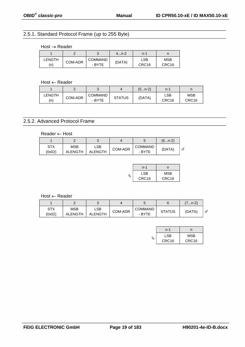
2.5.1. Standard Protocol Frame (up to 255 Byte)
Host Reader
1 2 3 4...n-2 n-1 n
LENGTH
(n) COM-ADR
COMMAND
- BYTE (DATA)
LSB
CRC16
MSB
CRC16
Host Reader
1 2 3 4 (5...n-2) n-1 n
LENGTH
(n) COM-ADR
COMMAND
- BYTE STATUS (DATA)
LSB
CRC16
MSB
CRC16
2.5.2. Advanced Protocol Frame
Reader Host
1 2 3 4 5 (6...n-2)
STX
(0x02)
MSB
ALENGTH
LSB
ALENGTH COM-ADR
COMMAND
- BYTE (DATA)
n-1 n
LSB
CRC16
MSB
CRC16
Host Reader
1 2 3 4 5 6 (7...n-2)
STX
(0x02)
MSB
ALENGTH
LSB
ALENGTH COM-ADR
COMMAND
- BYTE STATUS (DATA)
n-1 n
LSB
CRC16
MSB
CRC16
OBID® classic-pro Manual ID CPR50.10-xE / ID MAX50.10-xE
FEIG ELECTRONIC GmbH Page 20 of 183 H90201-4e-ID-B.docx
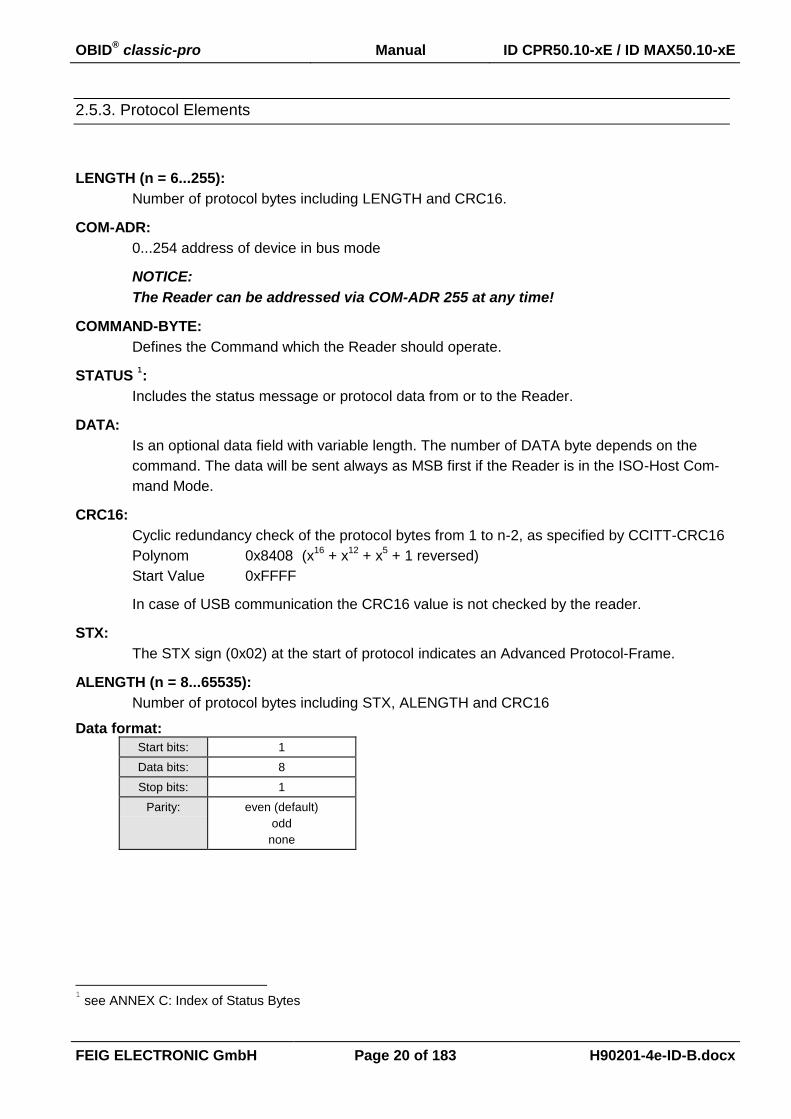
2.5.3. Protocol Elements
LENGTH (n = 6...255):
Number of protocol bytes including LENGTH and CRC16.
COM-ADR:
0...254 address of device in bus mode
NOTICE:
The Reader can be addressed via COM-ADR 255 at any time!
COMMAND-BYTE:
Defines the Command which the Reader should operate.
STATUS 1:
Includes the status message or protocol data from or to the Reader.
DATA:
Is an optional data field with variable length. The number of DATA byte depends on the
command. The data will be sent always as MSB first if the Reader is in the ISO-Host Com-
mand Mode.
CRC16:
Cyclic redundancy check of the protocol bytes from 1 to n-2, as specified by CCITT-CRC16
Polynom 0x8408 (x16
+ x12
+ x5 + 1 reversed)
Start Value 0xFFFF
In case of USB communication the CRC16 value is not checked by the reader.
STX:
The STX sign (0x02) at the start of protocol indicates an Advanced Protocol-Frame.
ALENGTH (n = 8...65535):
Number of protocol bytes including STX, ALENGTH and CRC16
Data format:
Start bits: 1
Data bits: 8
Stop bits: 1
Parity: even (default)
odd
none
1 see ANNEX C: Index of Status Bytes
OBID® classic-pro Manual ID CPR50.10-xE / ID MAX50.10-xE
FEIG ELECTRONIC GmbH Page 21 of 183 H90201-4e-ID-B.docx
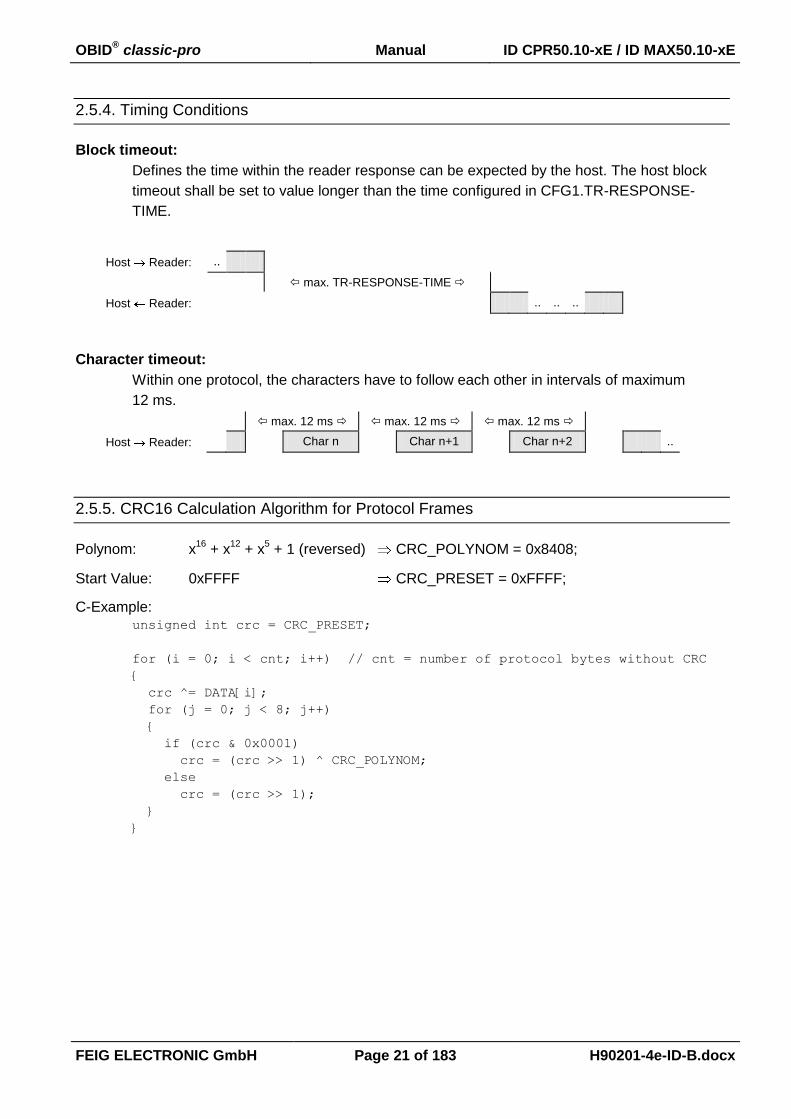
2.5.4. Timing Conditions
Block timeout:
Defines the time within the reader response can be expected by the host. The host block
timeout shall be set to value longer than the time configured in CFG1.TR-RESPONSE-
TIME.
Host Reader: ..
max. TR-RESPONSE-TIME
Host Reader: .. .. ..
Character timeout:
Within one protocol, the characters have to follow each other in intervals of maximum
12 ms.
max. 12 ms max. 12 ms max. 12 ms
Host Reader: Char n Char n+1 Char n+2 ..
2.5.5. CRC16 Calculation Algorithm for Protocol Frames
Polynom: x16
+ x12
+ x5 + 1 (reversed) CRC_POLYNOM = 0x8408;
Start Value: 0xFFFF CRC_PRESET = 0xFFFF;
C-Example: unsigned int crc = CRC_PRESET;
for (i = 0; i < cnt; i++) // cnt = number of protocol bytes without CRC
{
crc ^= DATA[i];
for (j = 0; j < 8; j++)
{
if (crc & 0x0001)
crc = (crc >> 1) ^ CRC_POLYNOM;
else
crc = (crc >> 1);
}
}
OBID® classic-pro Manual ID CPR50.10-xE / ID MAX50.10-xE
FEIG ELECTRONIC GmbH Page 22 of 183 H90201-4e-ID-B.docx
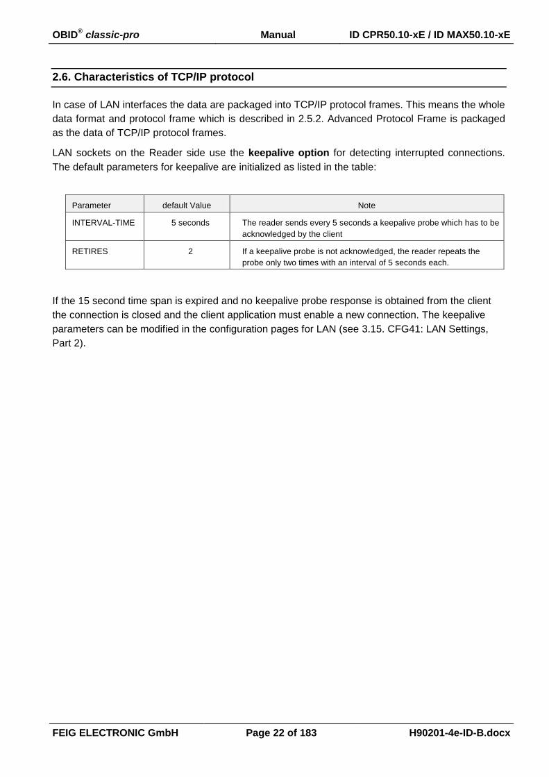
2.6. Characteristics of TCP/IP protocol
In case of LAN interfaces the data are packaged into TCP/IP protocol frames. This means the whole
data format and protocol frame which is described in 2.5.2. Advanced Protocol Frame is packaged
as the data of TCP/IP protocol frames.
LAN sockets on the Reader side use the keepalive option for detecting interrupted connections.
The default parameters for keepalive are initialized as listed in the table:
Parameter default Value Note
INTERVAL-TIME 5 seconds The reader sends every 5 seconds a keepalive probe which has to be
acknowledged by the client
RETIRES 2 If a keepalive probe is not acknowledged, the reader repeats the
probe only two times with an interval of 5 seconds each.
If the 15 second time span is expired and no keepalive probe response is obtained from the client
the connection is closed and the client application must enable a new connection. The keepalive
parameters can be modified in the configuration pages for LAN (see 3.15. CFG41: LAN Settings,
Part 2).

OBID® classic-pro Manual ID CPR50.10-xE / ID MAX50.10-xE
FEIG ELECTRONIC GmbH Page 23 of 183 H90201-4e-ID-B.docx
3. Configuration Parameters (CFG)
The configuration memory of the Reader is organized in configuration blocks of 16 byte each. These
are divided into 14-byte configuration parameters and a 2-byte CRC16 checksum. Each of these
configuration blocks takes a number (CFG 0...CFG n).
Structure of a configuration block in Reader configuration memory and Reader EEPROM (CFG):
Byte 0 1 2 3 4 5 6 7 8 9 10 11 12 13 14 15
Contents PARAMETER CRC16
The parameters are stored in two different configuration memory locations:
Reader RAM
Backup EEPROM (used for storing parameter over power down)
Multiple configuration memory locations can be addressed by the value of the parameter CFG-ADR
used in chapter 4. Commands for Reader Configuration
CFG-ADR:
CFGn: memory-address of the required configuration block
LOC: specifies the location of the configuration block (RAM / EEPROM)
MODE: specifies one or all configuration blocks
Bit: 7 6 5 4 3 2 1 0
Function LOC MODE CFGn: address of configuration block
The EEPROM configuration blocks are protected by a 16 bit CRC-checksum. The examination of
these checksums is executed after each reset of the Reader. If a faulty checksum is found, the
Reader goes into an error status "EE-Init-Mode" and sets the configuration block which is faulty to
the default values.
While the EE-Init-Mode is active, the LED blinks alternately red and green and the Reader answers
external commands with the status "0x10 EEPROM Failure". The "EE-Init-Mode" can be exited now
by a new reset (cold start or 5.1. [0x63] CPU Reset command). If after this the checksums of all
data records are correct, the Reader shifts to the configured operation mode.
Notes:
Malfunctions may occur if parameters are configured outside their described range or if
unspecified parameters have been changed!
A firmware update resets the EEPROM to default settings and the Reader goes into the
error status “EE-Init-mode”.

OBID® classic-pro Manual ID CPR50.10-xE / ID MAX50.10-xE
FEIG ELECTRONIC GmbH Page 24 of 183 H90201-4e-ID-B.docx
Structure of configuration parameter description.
Byte 0 1 2 ......n
contents RAM-eff. EEPROM-
eff.
00
res
.....
not marked Changing of this pa-rameter becomes im-mediately effective after writing / saving this configuration block to RAM
marked with “00“ these bits or bytes are reserved for future extensions or for in-ternal testing and manufactur-ing-functions. These bits or bytes and also any not de-
scribed bits and bytes must not
be changed, as this may cause faulty operation of the Reader.
gray marked Changing of this pa-rameter only becomes effective after writing / saving this configuration block to EEPROM and a Reader reset

OBID® classic-pro Manual ID CPR50.10-xE / ID MAX50.10-xE
FEIG ELECTRONIC GmbH Page 25 of 183 H90201-4e-ID-B.docx
3.1. CFG0: Crypto
The configuration block CFG0 defines the security of the reader.
Byte 0 1 2 3 4 5 6
Contents 0x00 0x00 0x00 0x00 0x00 0x00 0x00
Default 0x00 0x00 0x00 0x00 0x00 0x00 0x00
Byte 7 8 9 10 11 12 13
Contents 0x00 0x00 0x00 0x00 0x00 0x00 CRYPTO
Default 0x00 0x00 0x00 0x00 0x00 0x00 0x00
CRYPTO:
By setting of this parameter the interface-protocol can be change to crypto-mode
0x00: protocol is plain.
0x01: protocol is enciphered.

OBID® classic-pro Manual ID CPR50.10-xE / ID MAX50.10-xE
FEIG ELECTRONIC GmbH Page 26 of 183 H90201-4e-ID-B.docx
3.2. CFG1: Interface
The parameters of the CFG1 configuration block contain the data communication settings.
Byte 0 1 2 3 4 5 6
Contents 0x00 0x00 0x00 0x00
0x00
0x00
TR-
RESPONSE-
TIME
Default 0x00 0x00 0x00 0x00 0x00 0x00 0x00
Byte 7 8 9 10 11 12 13
Contents
TR-
RESPONSE-
TIME
0x00 0x00 0x00 0x00 INTERFACE READER -
MODE
Default 0x16 0x00 0x00 0x00 0x00 0x80 0x00
2,2 sec.
TR-RESPONSE-TIME:
By means of this parameter the maximum duration for the Transponder command can be
defined.
The TR-RESPONSE-TIME starts after the Reader has received a new command. At the
latest after the TR-RESPONSE-TIME elapsed the Reader will be sent an answer protocol.
In this case, the current commands between Reader and Transponder are aborted.
max. response duration
TR-RESPONSE-TIME 0...65535 * 100 ms
NOTICE:
TR-RESPONSE-TIME has no effect for commands for Reader Configuration and
Reader Control.
The block receive timeout of host computer must set to a value TR-RESPONSE-
TIME.
INTERFACE:
By setting of this parameter the Network-Discovery can be enabled
0x00: Network-Discovery disabled.
0x80: Network-Discovery enabled.
The Network-Discovery is the functionality that allows to discover and to setup the network configu-
ration of the FEIG-Network-Reader with UDP commands (UDP = User Data Protocol).
OBID® classic-pro Manual ID CPR50.10-xE / ID MAX50.10-xE
FEIG ELECTRONIC GmbH Page 27 of 183 H90201-4e-ID-B.docx
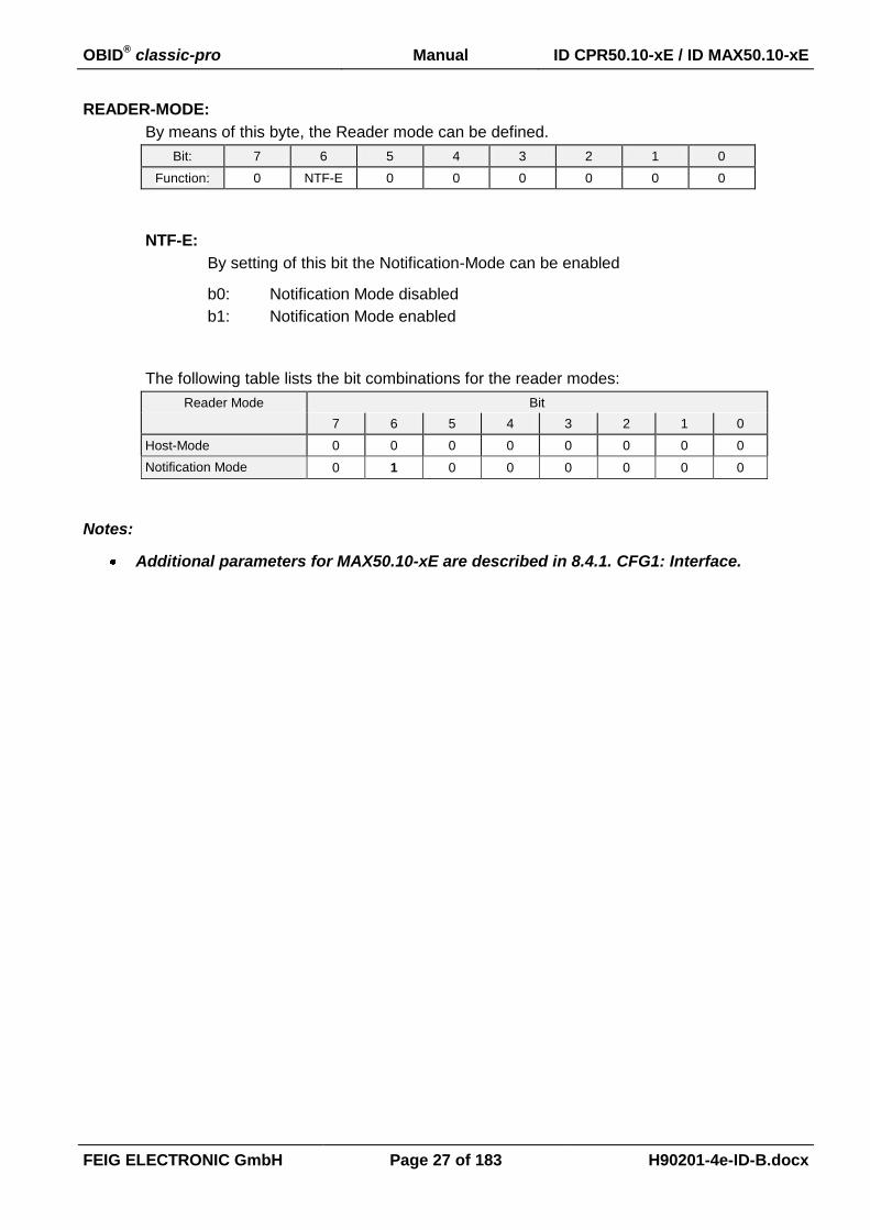
READER-MODE:
By means of this byte, the Reader mode can be defined.
Bit: 7 6 5 4 3 2 1 0
Function: 0 NTF-E 0 0 0 0 0 0
NTF-E:
By setting of this bit the Notification-Mode can be enabled
b0: Notification Mode disabled
b1: Notification Mode enabled
The following table lists the bit combinations for the reader modes:
Reader Mode Bit
7 6 5 4 3 2 1 0
Host-Mode 0 0 0 0 0 0 0 0
Notification Mode 0 1 0 0 0 0 0 0
Notes:
Additional parameters for MAX50.10-xE are described in 8.4.1. CFG1: Interface.

OBID® classic-pro Manual ID CPR50.10-xE / ID MAX50.10-xE
FEIG ELECTRONIC GmbH Page 28 of 183 H90201-4e-ID-B.docx
3.3. CFG2: Inputs / Outputs general
Via the following parameters the operation mode of the LED and the Buzzer can be configured indi-
vidual separate for offline, online and tag-detect conditions.
Byte 0 1 2 3 4 5 6
Contents 0x00 0x00 ONLINE-STATE INPUT-EVENT 0x00
Default 0x00 0x00 0x0004 0x0000 0x00
Byte 7 8 9 10 11 12 13
Contents OFFLINE-STATE OFFLINE-
DELAY TAGDETECT-STATE
TAGDETECT
ACTIVATION
TIME
CPRIO
ENABLE
Default 0x0008 0x64 0x0040 0x04 0x01
10 sec. 400 ms enabled
ONLINE-STATE:
This Parameter defines the behavior of the signal transmitters if they are not activated by
any other event.
Bit: 15 14 13 12 11 10 9 8
Function: - - - RELAY
Bit: 7 6 5 4 3 2 1 0
Function: BUZZER RED BLUE GRN
GRN / BLUE / RED / BUZZER / RELAY
The bit combination defines the behavior of the signal transmitter
b00: OFF
b01: ON
b10: FLASHING SLOW
b11: FLASHING FAST
INPUT-EVENT:
This parameter defines which digital input will activate a signal transmitter.
Bit: 15 14 13 12 11 10 9 8
Function: - - - - - - - -
Bit: 7 6 5 4 3 2 1 0
Function: IN_MSG - - - - - -
IN_MSG:
By setting of these bits the input message function can be configured. Message
OBID® classic-pro Manual ID CPR50.10-xE / ID MAX50.10-xE
FEIG ELECTRONIC GmbH Page 29 of 183 H90201-4e-ID-B.docx
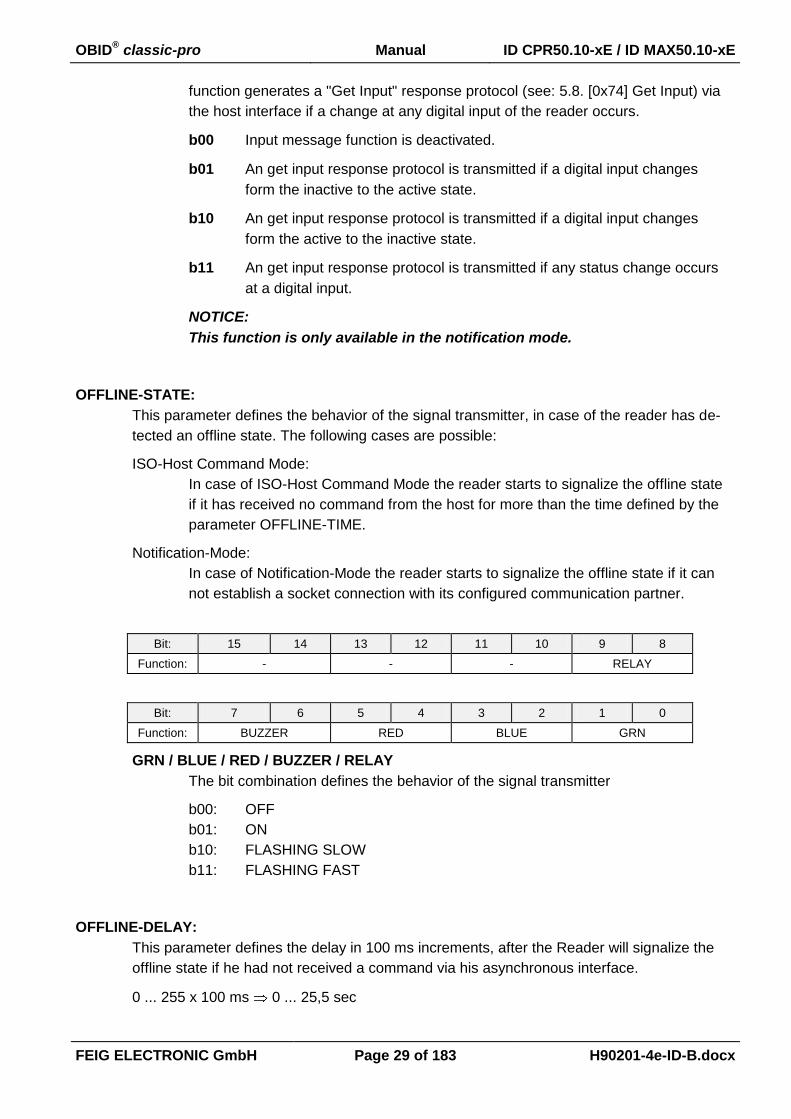
function generates a "Get Input" response protocol (see: 5.8. [0x74] Get Input) via
the host interface if a change at any digital input of the reader occurs.
b00 Input message function is deactivated.
b01 An get input response protocol is transmitted if a digital input changes
form the inactive to the active state.
b10 An get input response protocol is transmitted if a digital input changes
form the active to the inactive state.
b11 An get input response protocol is transmitted if any status change occurs
at a digital input.
NOTICE:
This function is only available in the notification mode.
OFFLINE-STATE:
This parameter defines the behavior of the signal transmitter, in case of the reader has de-
tected an offline state. The following cases are possible:
ISO-Host Command Mode:
In case of ISO-Host Command Mode the reader starts to signalize the offline state
if it has received no command from the host for more than the time defined by the
parameter OFFLINE-TIME.
Notification-Mode:
In case of Notification-Mode the reader starts to signalize the offline state if it can
not establish a socket connection with its configured communication partner.
Bit: 15 14 13 12 11 10 9 8
Function: - - - RELAY
Bit: 7 6 5 4 3 2 1 0
Function: BUZZER RED BLUE GRN
GRN / BLUE / RED / BUZZER / RELAY
The bit combination defines the behavior of the signal transmitter
b00: OFF
b01: ON
b10: FLASHING SLOW
b11: FLASHING FAST
OFFLINE-DELAY:
This parameter defines the delay in 100 ms increments, after the Reader will signalize the
offline state if he had not received a command via his asynchronous interface.
0 ... 255 x 100 ms 0 ... 25,5 sec
OBID® classic-pro Manual ID CPR50.10-xE / ID MAX50.10-xE
FEIG ELECTRONIC GmbH Page 30 of 183 H90201-4e-ID-B.docx
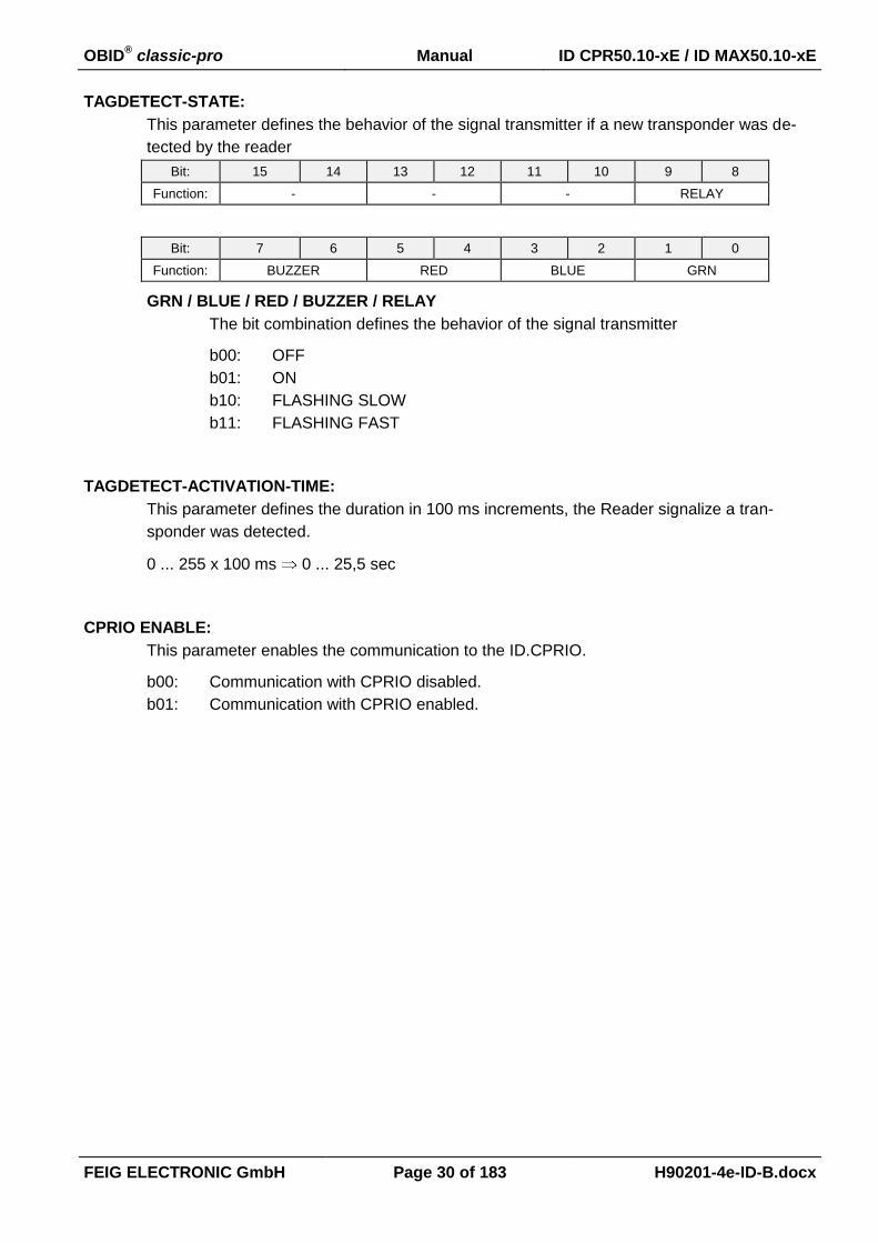
TAGDETECT-STATE:
This parameter defines the behavior of the signal transmitter if a new transponder was de-
tected by the reader
Bit: 15 14 13 12 11 10 9 8
Function: - - - RELAY
Bit: 7 6 5 4 3 2 1 0
Function: BUZZER RED BLUE GRN
GRN / BLUE / RED / BUZZER / RELAY
The bit combination defines the behavior of the signal transmitter
b00: OFF
b01: ON
b10: FLASHING SLOW
b11: FLASHING FAST
TAGDETECT-ACTIVATION-TIME:
This parameter defines the duration in 100 ms increments, the Reader signalize a tran-
sponder was detected.
0 ... 255 x 100 ms 0 ... 25,5 sec
CPRIO ENABLE:
This parameter enables the communication to the ID.CPRIO.
b00: Communication with CPRIO disabled.
b01: Communication with CPRIO enabled.

OBID® classic-pro Manual ID CPR50.10-xE / ID MAX50.10-xE
FEIG ELECTRONIC GmbH Page 31 of 183 H90201-4e-ID-B.docx
3.4. CFG3: RF-Interface
The parameters of the CFG3 configuration block contain global Transponder driver and Reader set-
tings.
Byte 0 1 2 3 4 5 6
Contents TAG-DRV ISO14443-DRV 0x00 0x00 0x00
Default 0x0038 0x000F 0x00 0x00 0x00
Byte 7 8 9 10 11 12 13
Contents ISO14443
BIT RATE
0x00 0x00 0x00 0x00 0x00 ISO14443
FTUR
Default 0xF0 0x00 0x00 0x00 0x00 0x03 0x10
TAG-DRV1:
Defines the Transponder types that are operated by the Reader.
Byte: 0 1
Bit: 15 14 13 12 11 10 9 8 7 6 5 4 3 2 1 0
Driver 0 O 0 0 L K 0 I 0 G F E D 0 0 0
Default 0 1 0 0 1 1 0 1 0 0 1 1 1 0 0 0
b0: Driver for the Transponder type is disabled
b1: Driver for the Transponder type is activated
.D: Driver for ISO15693
.E: Driver for ISO14443A
.F: Driver for ISO14443B
Only those Transponder drivers should be active that are used in the current appli-
cation. Thus, the reaction time of the Reader for Transponder read- / write-
operations is reduced and the danger of a parasitic Transponder access is mini-
mized.
1 A plausibility check is performed by writing this parameter to the Reader. If an error occurs the Reader an-swers with STATUS = 0x11.
OBID® classic-pro Manual ID CPR50.10-xE / ID MAX50.10-xE
FEIG ELECTRONIC GmbH Page 32 of 183 H90201-4e-ID-B.docx
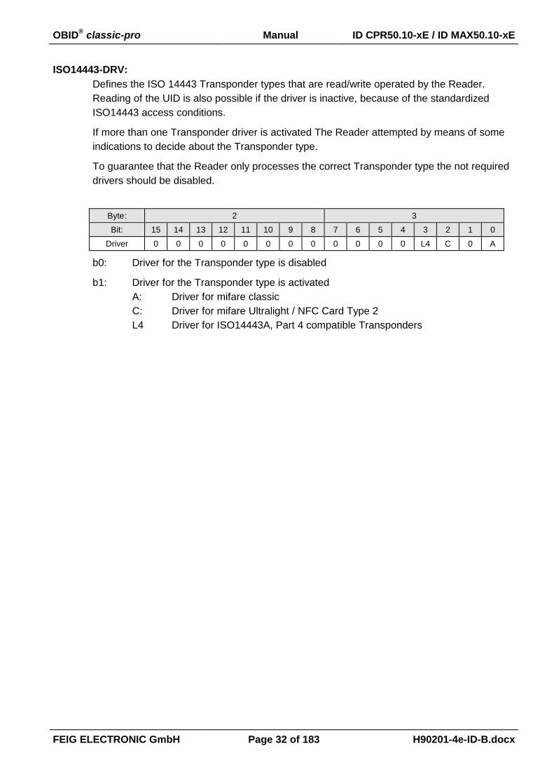
ISO14443-DRV:
Defines the ISO 14443 Transponder types that are read/write operated by the Reader.
Reading of the UID is also possible if the driver is inactive, because of the standardized
ISO14443 access conditions.
If more than one Transponder driver is activated The Reader attempted by means of some
indications to decide about the Transponder type.
To guarantee that the Reader only processes the correct Transponder type the not required
drivers should be disabled.
Byte: 2 3
Bit: 15 14 13 12 11 10 9 8 7 6 5 4 3 2 1 0
Driver 0 0 0 0 0 0 0 0 0 0 0 0 L4 C 0 A
b0: Driver for the Transponder type is disabled
b1: Driver for the Transponder type is activated
A: Driver for mifare classic
C: Driver for mifare Ultralight / NFC Card Type 2
L4 Driver for ISO14443A, Part 4 compatible Transponders

OBID® classic-pro Manual ID CPR50.10-xE / ID MAX50.10-xE
FEIG ELECTRONIC GmbH Page 33 of 183 H90201-4e-ID-B.docx
ISO14443 BIT RATE:
This parameter defines the highest Bit-Rate which should be used by the Reader. The ac-
tual used Bit-Rate depends on the capabilities of the present Transponder. If the adjusted
Bit-Rate is not support by the Transponder the Reader select the highest supported Bit-
Rate of the Transponder.
Bit: 7 6 5 4 3 2 1 0
Function Tx BIT RATE Rx BIT RATE - - - -
TX BIT RATE
Used for bit rate selection from Reader to Transponder
b00: 106 kbit / s
b01: 212 kbit / s
b10: 424 kbit / s
b11: 848 kbit / s
RX BIT RATE
Used for bit rate selection from Transponder to Reader
b00: 106 kbit / s
b01: 212 kbit / s
b10: 424 kbit / s
b11: 848 kbit / s
NOTICE:
A high Bit-Rate could effect a reduction of the reading distance and the data
stream between Reader and Transponder could be interrupted by noisy environ-
ments.
ISO14443 FTUR:
In this parameter byte are some special features combined.
Bit: 7 6 5 4 3 2 1 0
Function UID-
ORDER
OPTI ERROR_RETRY PLIC BSLCT
BSLCT (only ISO 14443B Transponder)
This bit selects the response behavior for ISO 14443B Transponder with Bit-Rates
above 106 kBit / s.
The Reader principally use 106 kBit / for the first communication cycle. If the Tran-
sponder supports a higher Bit-Rate and this is configured by the parameter
ISO14443 BIT RATE the Reader selects the highest possible Bit-Rate.
Unfortunately the reception from the Transponder could be on 106 kBit / s ore on
the new higher Bit-Rate.

OBID® classic-pro Manual ID CPR50.10-xE / ID MAX50.10-xE
FEIG ELECTRONIC GmbH Page 34 of 183 H90201-4e-ID-B.docx
b0: The first reception after a Bit-Rate change is expected with 106 kBit / s.
b1: The first reception after a Bit-Rate change is expected with the selected
higher Bit-Rate.
PLIC (only ISO 14443-4 Transponder)
This bit enables the power level indicator check function of the Reader.
b0: Power level check is disabled.
b1: Power level check is enabled.
The power level indicator of ISO 14443-4 Transponders will be interpreted
by the Reader if it is supported by the Transponder.
If a Transponder response indicates insufficient power the Reader breaks
the present command and sends an error status.
ERROR_RETRY (only ISO 14443-4 Transponder)
This parameter defines the maximum number of automatic retry loops in case of
transmission or protocol errors as described in ISO 14443-4.
b00: disables retry loop
b01: 1 retry loop
b10 2 retry loops
b11: 3 retry loops
OPTI (only ISO14443A Transponder)
By means of this bit some optional information's could be displayed for ISO14443A
in the [0x01] inventory response byte OPT_INFO (see also 6.1.1. [0x01] Inventory)
b0: The OPT_INFO byte in [0x01] inventory response is always set to 0.
b1: The OPT_INFO byte in [0x01] inventory response includes further Infor-
mation's.
UID_ORDER (only ISO14443A Transponder)
By means of this bit the byte order of the UID of ISO14443A Transponder can be
swapped.
b0: The UID will be transferred as described in 6.1.1.1. Response-Data - ISO
14443A (TR-TYPE = 0x04).
b1: The byte order of the transferred UID will be swapped (UID transfer will be
carried out like described in ISO14443).
OBID® classic-pro Manual ID CPR50.10-xE / ID MAX50.10-xE
FEIG ELECTRONIC GmbH Page 35 of 183 H90201-4e-ID-B.docx
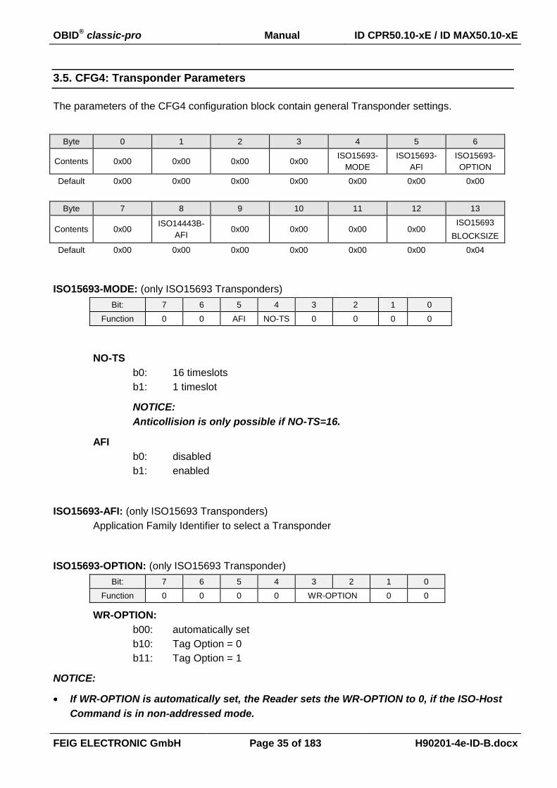
3.5. CFG4: Transponder Parameters
The parameters of the CFG4 configuration block contain general Transponder settings.
Byte 0 1 2 3 4 5 6
Contents 0x00 0x00 0x00 0x00 ISO15693-
MODE
ISO15693-
AFI
ISO15693-
OPTION
Default 0x00 0x00 0x00 0x00 0x00 0x00 0x00
Byte 7 8 9 10 11 12 13
Contents 0x00 ISO14443B-
AFI 0x00 0x00 0x00 0x00
ISO15693
BLOCKSIZE
Default 0x00 0x00 0x00 0x00 0x00 0x00 0x04
ISO15693-MODE: (only ISO15693 Transponders)
Bit: 7 6 5 4 3 2 1 0
Function 0 0 AFI NO-TS 0 0 0 0
NO-TS
b0: 16 timeslots
b1: 1 timeslot
NOTICE:
Anticollision is only possible if NO-TS=16.
AFI
b0: disabled
b1: enabled
ISO15693-AFI: (only ISO15693 Transponders)
Application Family Identifier to select a Transponder
ISO15693-OPTION: (only ISO15693 Transponder)
Bit: 7 6 5 4 3 2 1 0
Function 0 0 0 0 WR-OPTION 0 0
WR-OPTION:
b00: automatically set
b10: Tag Option = 0
b11: Tag Option = 1
NOTICE:
If WR-OPTION is automatically set, the Reader sets the WR-OPTION to 0, if the ISO-Host
Command is in non-addressed mode.
OBID® classic-pro Manual ID CPR50.10-xE / ID MAX50.10-xE
FEIG ELECTRONIC GmbH Page 36 of 183 H90201-4e-ID-B.docx
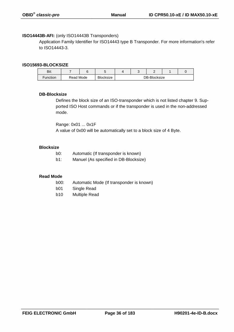
ISO14443B-AFI: (only ISO14443B Transponders)
Application Family Identifier for ISO14443 type B Transponder. For more information's refer
to ISO14443-3.
ISO15693-BLOCKSIZE
Bit: 7 6 5 4 3 2 1 0
Function Read Mode Blocksize DB-Blocksize
DB-Blocksize
Defines the block size of an ISO-transponder which is not listed chapter 9. Sup-
ported ISO Host commands or if the transponder is used in the non-addressed
mode.
Range: 0x01 ... 0x1F
A value of 0x00 will be automatically set to a block size of 4 Byte.
Blocksize
b0: Automatic (If transponder is known)
b1: Manuel (As specified in DB-Blocksize)
Read Mode
b00: Automatic Mode (If transponder is known)
b01 Single Read
b10 Multiple Read

OBID® classic-pro Manual ID CPR50.10-xE / ID MAX50.10-xE
FEIG ELECTRONIC GmbH Page 37 of 183 H90201-4e-ID-B.docx
3.6. CFG5: Anticollision
The parameters of the CFG5 configuration block contain anticollision settings.
Byte 0 1 2 3 4 5 6
Contents 0x00 0x00 0x00 0x00 0x00 0x00 0x00
Default 0x00 0x00 0x00 0x00 0x00 0x00 0x00
Byte 7 8 9 10 11 12 13
Contents 0x00 0x00 0x00 0x00 ONT 0x00 0x00
Default 0x00 0x00 0x00 0x00 0x04 0x00 0x00
ONT:
This parameter configures the reply behavior of the Inventory command [0x01]. It defines
which Transponder will reply to the host.
Bit: 7 6 5 4 3 2 1 0
Function 0
0
0
0
0
AC
OL
L
0
0
ACOLL:
This bit activates Anticollision Mode. In Anticollision Mode the Reader automatical-
ly sets Transponder-specific communication parameters.
b0: disabled
In this case the Reader doesn’t process any anticollision procedure with
the Transponders inside the antenna field.
If anticollision is disabled, the Reader automatically selects the Tran-
sponder. The Select command [0x25] is not necessary for further com-
munication with the Transponder.
If more than one Transponder of the same type is in the detection range
the Reader replies an error status.
b1: enabled (default)
In this case the Reader processes the anticollision procedure with the
Transponders inside of the antenna field and replies the UID of all detect-
ed Transponder's.

OBID® classic-pro Manual ID CPR50.10-xE / ID MAX50.10-xE
FEIG ELECTRONIC GmbH Page 38 of 183 H90201-4e-ID-B.docx
3.7. CFG6 .. 10: Reserved
3.8. CFG11: Read Mode – Read Data 1
The parameters of the CFG11 configuration block contain Notification Mode settings. The Notifica-
tion Mode can be enabled by setting the READER-MODE register of the configuration block 3.2.
CFG1: Interface. It may be useful to enable “Anticollision Select Mode” in 3.6. CFG5: Anticollision if
there is a large or unknown number of Transponders expected in the antenna field.
Byte 0 1 2 3 4 5 6
Contents TR-DATA-1 TR-DATA-2 0x00 0x00 DB-ADR 1 0x00
Default 0x01 0x00 0x00 0x00 0x0000 0x00
Byte 7 8 9 10 11 12 13
Contents 0x00 DB-N 2 0x00 0x00 0x00 0x00
Default 0x00 0x0001 0x00 0x00 0x00 0x40
TR-DATA-1:
Selects the data types for read operation.
Bit: 7 6 5 4 3 2 1 0
Function Exten-
sion
0 0 0 Byte
Order
0 DB SNR
SNR:
b0: no Serial Number will be transmitted
b1: Serial Number will be transmitted
DB:
b0: no data block will be transmitted
b1: data block will be transmitted
Byte Order:
By this bit the byte order of the data block can be swapped.
b0: MSB first
b1: LSB first
Extension:
If this flag is set TR-DATA-2 is present
1 A reasonableness check is performed by writing this parameter to the Reader. If an error occurs the Reader answers with STATUS = [0x11].
2 A plausibility check is performed by writing this parameter to the Reader. If an error occurs the Reader

OBID® classic-pro Manual ID CPR50.10-xE / ID MAX50.10-xE
FEIG ELECTRONIC GmbH Page 39 of 183 H90201-4e-ID-B.docx
TR-DATA-2:
Selects the data types for read operation.
Bit: 7 6 5 4 3 2 1 0
Function - - - - - - MAC -
MAC:
MAC-Address of Reader will be transmitted.
DB-ADR:
Address of first data block. Range: 0x00...0xFF.
DB-N:
Number of data blocks. Range: 64 Bytes of data.
Notes:
Additional parameters for MAX50.10-xE are described in 8.4.2. CFG11: Read Mode –
Read Data 1.

OBID® classic-pro Manual ID CPR50.10-xE / ID MAX50.10-xE
FEIG ELECTRONIC GmbH Page 40 of 183 H90201-4e-ID-B.docx
3.9. CFG12: Read Mode - Filter
Byte 0 1 2 3 4 5 6
0x00 VALID-TIME1
0x00 0x00 0x00 0x00 0x00
Default 0x0037 0x00 0x00 0x00 0x00 0x00
5,5 sec.
Byte 7 8 9 10 11 12 13
Contents 0x00 0x00 0x00 0x00 0x00 0x00 0x00
Default 0x00 0x00 0x00 0x00 0x00 0x00 0x00
VALID-TIME: (0...65535 x 100 ms = 0 ms ... 6553,5 sec)
The period of time during which a Transponder can’t be read a 2nd
time.
Notes:
Changing of VALID-TIME only becomes effective after writing / saving configura-
tion block CFG12 to EEPROM and reset of the RFC-Controller with 5.2. [0x64] Sys-
tem Reset in mode 0x00.
3.10. CFG13 .. 14: Reserved
Notes:
Additional parameters for MAX50.10-xE are described in 8.4.3. CFG14: Access
Control.
1 DB-ADR, DB-N of CFG11
OBID® classic-pro Manual ID CPR50.10-xE / ID MAX50.10-xE
FEIG ELECTRONIC GmbH Page 41 of 183 H90201-4e-ID-B.docx
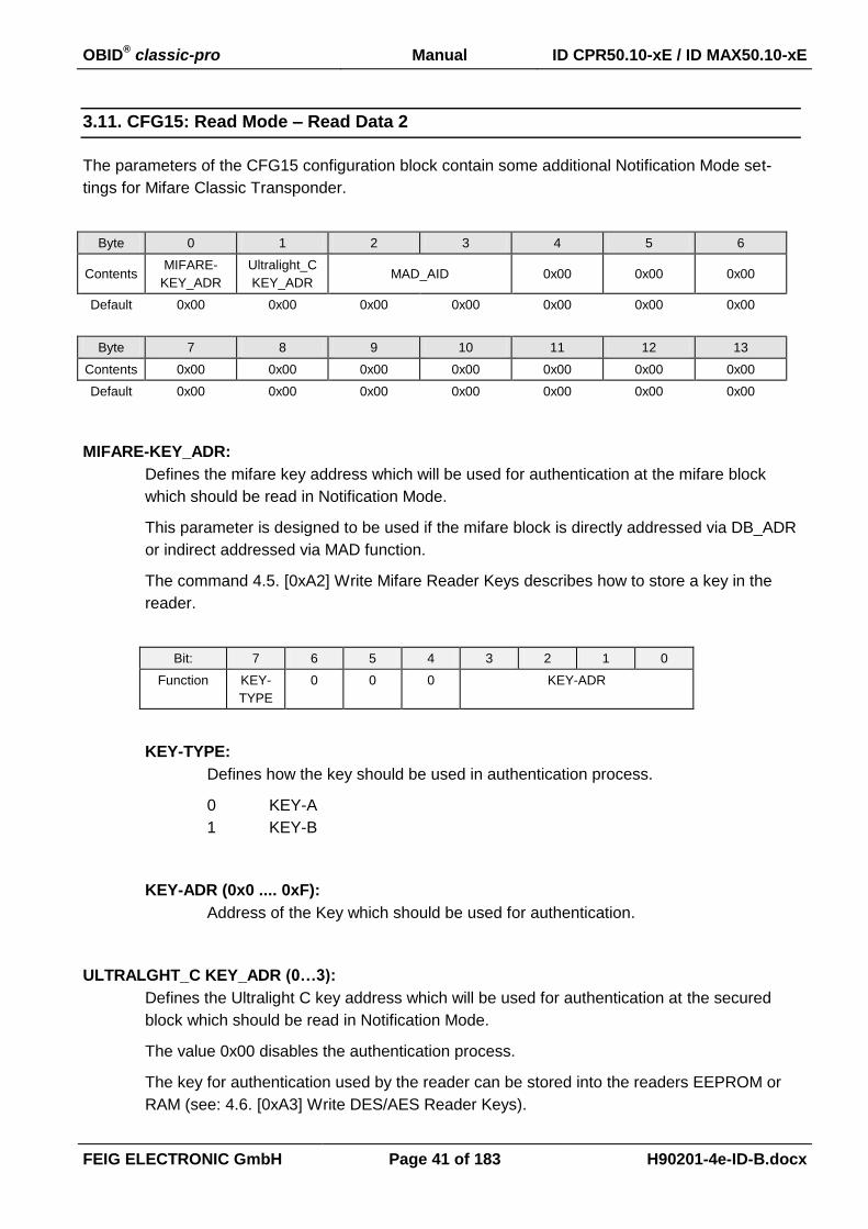
3.11. CFG15: Read Mode – Read Data 2
The parameters of the CFG15 configuration block contain some additional Notification Mode set-
tings for Mifare Classic Transponder.
Byte 0 1 2 3 4 5 6
Contents MIFARE-
KEY_ADR
Ultralight_C
KEY_ADR MAD_AID 0x00 0x00 0x00
Default 0x00 0x00 0x00 0x00 0x00 0x00 0x00
Byte 7 8 9 10 11 12 13
Contents 0x00 0x00 0x00 0x00 0x00 0x00 0x00
Default 0x00 0x00 0x00 0x00 0x00 0x00 0x00
MIFARE-KEY_ADR:
Defines the mifare key address which will be used for authentication at the mifare block
which should be read in Notification Mode.
This parameter is designed to be used if the mifare block is directly addressed via DB_ADR
or indirect addressed via MAD function.
The command 4.5. [0xA2] Write Mifare Reader Keys describes how to store a key in the
reader.
Bit: 7 6 5 4 3 2 1 0
Function KEY-
TYPE
0 0 0 KEY-ADR
KEY-TYPE:
Defines how the key should be used in authentication process.
0 KEY-A
1 KEY-B
KEY-ADR (0x0 .... 0xF):
Address of the Key which should be used for authentication.
ULTRALGHT_C KEY_ADR (0…3):
Defines the Ultralight C key address which will be used for authentication at the secured
block which should be read in Notification Mode.
The value 0x00 disables the authentication process.
The key for authentication used by the reader can be stored into the readers EEPROM or
RAM (see: 4.6. [0xA3] Write DES/AES Reader Keys).
OBID® classic-pro Manual ID CPR50.10-xE / ID MAX50.10-xE
FEIG ELECTRONIC GmbH Page 42 of 183 H90201-4e-ID-B.docx
MAD_AID:
Parameter to configure the 2 byte AID (Application Identifier) of the MAD function. Setting
an AID (Application Identifier) activates the MAD function for reading data blocks of mifare
classic Transponders. It becomes only effect if the DB bit is set to 1.
OBID® classic-pro Manual ID CPR50.10-xE / ID MAX50.10-xE
FEIG ELECTRONIC GmbH Page 43 of 183 H90201-4e-ID-B.docx
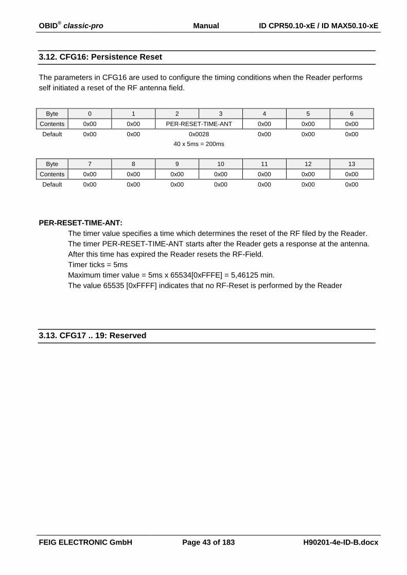
3.12. CFG16: Persistence Reset
The parameters in CFG16 are used to configure the timing conditions when the Reader performs
self initiated a reset of the RF antenna field.
Byte 0 1 2 3 4 5 6
Contents 0x00 0x00 PER-RESET-TIME-ANT 0x00 0x00 0x00
Default 0x00 0x00 0x0028 0x00 0x00 0x00
40 x 5ms = 200ms
Byte 7 8 9 10 11 12 13
Contents 0x00 0x00 0x00 0x00 0x00 0x00 0x00
Default 0x00 0x00 0x00 0x00 0x00 0x00 0x00
PER-RESET-TIME-ANT:
The timer value specifies a time which determines the reset of the RF filed by the Reader.
The timer PER-RESET-TIME-ANT starts after the Reader gets a response at the antenna.
After this time has expired the Reader resets the RF-Field.
Timer ticks = 5ms
Maximum timer value = 5ms x 65534[0xFFFE] = 5,46125 min.
The value 65535 [0xFFFF] indicates that no RF-Reset is performed by the Reader
3.13. CFG17 .. 19: Reserved
OBID® classic-pro Manual ID CPR50.10-xE / ID MAX50.10-xE
FEIG ELECTRONIC GmbH Page 44 of 183 H90201-4e-ID-B.docx
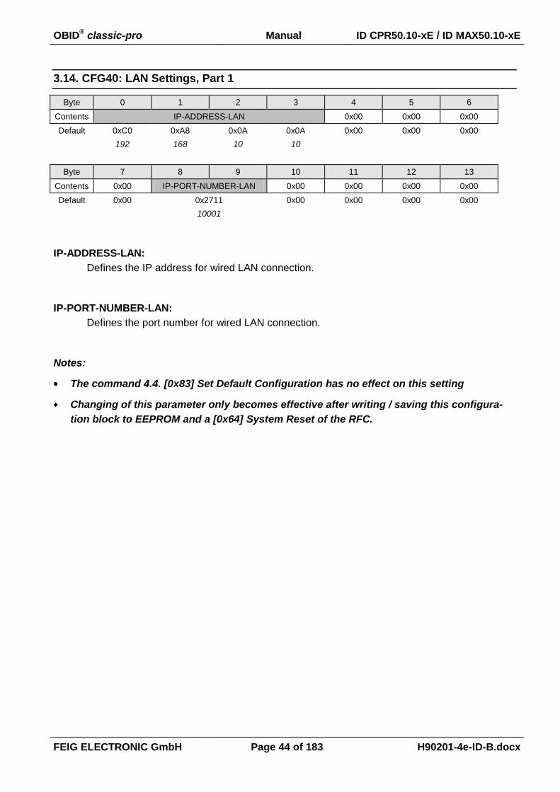
3.14. CFG40: LAN Settings, Part 1
Byte 0 1 2 3 4 5 6
Contents IP-ADDRESS-LAN 0x00 0x00 0x00
Default 0xC0 0xA8 0x0A 0x0A 0x00 0x00 0x00
192 168 10 10
Byte 7 8 9 10 11 12 13
Contents 0x00 IP-PORT-NUMBER-LAN 0x00 0x00 0x00 0x00
Default 0x00 0x2711 0x00 0x00 0x00 0x00
10001
IP-ADDRESS-LAN:
Defines the IP address for wired LAN connection.
IP-PORT-NUMBER-LAN:
Defines the port number for wired LAN connection.
Notes:
The command 4.4. [0x83] Set Default Configuration has no effect on this setting
Changing of this parameter only becomes effective after writing / saving this configura-
tion block to EEPROM and a [0x64] System Reset of the RFC.

OBID® classic-pro Manual ID CPR50.10-xE / ID MAX50.10-xE
FEIG ELECTRONIC GmbH Page 45 of 183 H90201-4e-ID-B.docx
3.15. CFG41: LAN Settings, Part 2
Byte 0 1 2 3 4 5 6
Contents
SUBNET-MASK-LAN LAN-
OPTIONS RETRIES
GW-
ADDRES-
LAN
Default 0xFF 0xFF 0x00 0x00 0x01 0x02 0x00
255 255 0 0 2
Byte 7 8 9 10 11 12 13
Contents GW-ADDRES-LAN 0x00 0x00 INTERVAL-TIME
Default 0x00 0x00 0x00 0x00 0x00 0x00 0x05
5 sec.
SUBNET-MASK-LAN:
Defines the subnet mask for wired TCP/IP connection.
GW-ADDRESS-LAN:
Defines the gateway address for TCP/IP connection.
LAN-OPTIONS:
Bit: 7 6 5 4 3 2 1 0
Function: DHCP SPEED 0 0 0 0 0 KEEP-
ALIVE
KEEP-ALIVE:
b0: Keep-Alive option disabled.
b1: Keep-Alive option enabled.
DHCP:
b0: dhcp-client disabled.
b1: dhcp-client enabled.
SPEED:
b0: Support for 10BASE-T (Full / Half duplex) only.
b1: Support for 10BASE-T (Full / Half duplex) and 100BASE-TX (Full / Half
Duplex).
RETRIES:
Specifies the maximum number of retransmissions. This is the number of times that the
reader re-transmits a keepalive packet to the host to check for connectivity. The valid range
is 1..255.

OBID® classic-pro Manual ID CPR50.10-xE / ID MAX50.10-xE
FEIG ELECTRONIC GmbH Page 46 of 183 H90201-4e-ID-B.docx
INTERVAL-TIME:
Set the Keepalive Interval. This is the polling frequency used to determine if a keepalive ex-
change is needed. This interval is used when the connection failed. The valid range is 1..255
sec.
Notes:
The command 4.4. [0x83] Set Default Configuration has no effect on this setting
Changing of this parameter only becomes effective after writing / saving this configura-
tion block to EEPROM and a [0x64] System Reset of the RFC.

OBID® classic-pro Manual ID CPR50.10-xE / ID MAX50.10-xE
FEIG ELECTRONIC GmbH Page 47 of 183 H90201-4e-ID-B.docx
3.16. CFG49: Notification Channel
Byte 0 1 2 3 4 5 6
Contents 0x00 0x00 0x00 0x00 KEEP-ALIVE KEEP-ALIVE-TIME
Default 0x00 0x00 0x00 0x00 0x00 0x00 0x00
off
Byte 7 8 9 10 11 12 13
Contents DEST-IP-ADDRESS DEST-IP-PORT HOLD-TIME
Default 0x00 0x00 0x00 0x00 0x00 0x00 0x01
KEEP-ALIVE:
Mode for keepalive notification.
Bit: 7 6 5 4 3 2 1 0
Function 0 0 0 0 0 0 0 EN
EN:
b0: disabled
b1: enabled
KEEP-ALIVE-TIME:
Defines the cycle time for keepalive notification.
max. time period
KEEP-ALIVE-TIME 0...65535 * 1s
DEST-IP-ADDRESS:
Defines the destination IP address.
DEST-IP-PORT-NUMBER:
Defines the destination port number.
HOLD-TIME:
Defines the hold time of the TCP/IP connection after sent of a notification. The time will be
retriggered with every new notification
OBID® classic-pro Manual ID CPR50.10-xE / ID MAX50.10-xE
FEIG ELECTRONIC GmbH Page 48 of 183 H90201-4e-ID-B.docx
4. Commands for Reader Configuration
Via the command protocols for the Reader configuration, the Reader may be adapted to individual
conditions of application within wide limits.
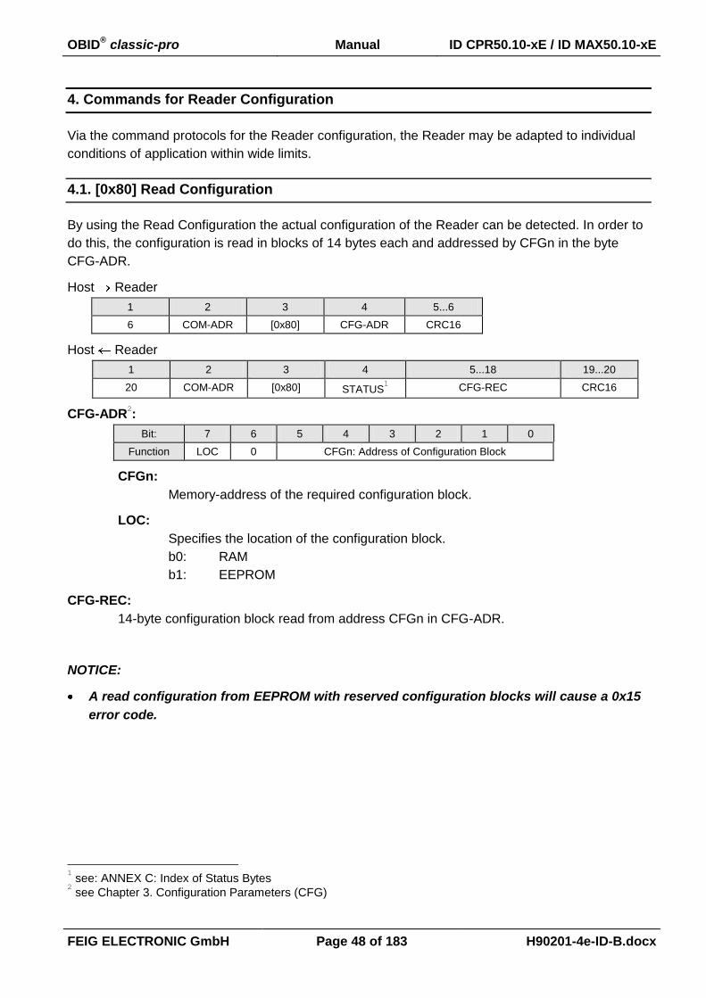
4.1. [0x80] Read Configuration
By using the Read Configuration the actual configuration of the Reader can be detected. In order to
do this, the configuration is read in blocks of 14 bytes each and addressed by CFGn in the byte
CFG-ADR.
Host Reader
1 2 3 4 5...6
6 COM-ADR [0x80] CFG-ADR CRC16
Host Reader
1 2 3 4 5...18 19...20
20 COM-ADR [0x80] STATUS1 CFG-REC CRC16
CFG-ADR2:
Bit: 7 6 5 4 3 2 1 0
Function LOC 0 CFGn: Address of Configuration Block
CFGn:
Memory-address of the required configuration block.
LOC:
Specifies the location of the configuration block.
b0: RAM
b1: EEPROM
CFG-REC:
14-byte configuration block read from address CFGn in CFG-ADR.
NOTICE:
A read configuration from EEPROM with reserved configuration blocks will cause a 0x15
error code.
1 see: ANNEX C: Index of Status Bytes 2 see Chapter 3. Configuration Parameters (CFG)

OBID® classic-pro Manual ID CPR50.10-xE / ID MAX50.10-xE
FEIG ELECTRONIC GmbH Page 49 of 183 H90201-4e-ID-B.docx
4.2. [0x81] Write Configuration
Via the command Write Configuration the configuration of the Reader can be changed. In order to
do this, the configuration memory is written on with 14 bytes long blocks and addressed by CFGn in
the byte CFG-ADR. The description of parameters can be taken from chapter 3. Configuration Pa-
rameters (CFG)
Host Reader
1 2 3 4 5...18 19...20
20 COM-ADR [0x81] CFG-ADR CFG-REC CRC16
Host Reader
1 2 3 4 5...6
6 COM-ADR [0x81] STATUS1 CRC16
CFG-ADR2:
Bit: 7 6 5 4 3 2 1 0
Function LOC 0 CFGn: Address of Configuration Block
CFGn: Memory-address of the required configuration block.
LOC: Specifies the location of the configuration block.
b0 RAM
b1 EEPROM and RAM
CFG-REC:
14-byte configuration block stored in the configuration memory of the Reader at
address CFGn.
NOTICE:
A write configuration to EEPROM with reserved configuration blocks will cause a 0x16 error
code.
1 see: ANNEX C: Index of Status Bytes 2 see chapter 3. Configuration Parameters (CFG)
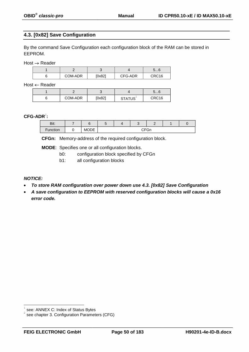
OBID® classic-pro Manual ID CPR50.10-xE / ID MAX50.10-xE
FEIG ELECTRONIC GmbH Page 50 of 183 H90201-4e-ID-B.docx
4.3. [0x82] Save Configuration
By the command Save Configuration each configuration block of the RAM can be stored in
EEPROM.
Host Reader
1 2 3 4 5...6
6 COM-ADR [0x82] CFG-ADR CRC16
Host Reader
1 2 3 4 5...6
6 COM-ADR [0x82] STATUS1 CRC16
CFG-ADR2:
Bit: 7 6 5 4 3 2 1 0
Function 0 MODE CFGn
CFGn: Memory-address of the required configuration block.
MODE: Specifies one or all configuration blocks.
b0: configuration block specified by CFGn
b1: all configuration blocks
NOTICE:
To store RAM configuration over power down use 4.3. [0x82] Save Configuration
A save configuration to EEPROM with reserved configuration blocks will cause a 0x16
error code.
1 see: ANNEX C: Index of Status Bytes 2 see chapter 3. Configuration Parameters (CFG)

OBID® classic-pro Manual ID CPR50.10-xE / ID MAX50.10-xE
FEIG ELECTRONIC GmbH Page 51 of 183 H90201-4e-ID-B.docx
4.4. [0x83] Set Default Configuration
Using the command Set Default Configuration each configuration block can be reset to the manu-
facturer's setting.
Host Reader
1 2 3 4 5...6
6 COM-ADR [0x83] CFG-ADR CRC16
Host Reader
1 2 3 4 5...6
6 COM-ADR [0x83] STATUS CRC16
CFG-ADR:
Bit: 7 6 5 4 3 2 1 0
Function LOC MODE CFGn
CFGn: Memory-address of the required configuration block.
MODE: Specifies one or all configuration blocks.
b0: configuration block specified by CFGn
b1: all configuration blocks
LOC: Specifies the location of the configuration block.
b0: RAM
b1: EEPROM
Notes:
To store RAM configuration over power down use 4.3. [0x82] Save Configuration
A set default configuration with reserved configuration blocks will cause an error code.

OBID® classic-pro Manual ID CPR50.10-xE / ID MAX50.10-xE
FEIG ELECTRONIC GmbH Page 52 of 183 H90201-4e-ID-B.docx
4.5. [0xA2] Write Mifare Reader Keys
The keys which are required by the Reader in order to authentify itself to a Mifare ISO14443A Tran-
sponder will be stored by this command. Only if the keys of the Reader and of the Transponder cor-
respond, the data exchange between Reader and Transponder can be effected.
Host Reader
1 2 3 4 5 6...11 12...13
13 COM-ADR 0xA2 KEY-TYPE KEY-ADR KEY CRC16
Host Reader
1 2 3 4 5...6
6 COM-ADR 0xA2 STATUS CRC16
KEY-TYPE:
Defines the key for the authentication.
0x00 KEY-A
0x01 KEY-B
KEY-ADR: (0x00 .... 0x0F)
Address where the key is stored in the reader. The address can be any value between 0
and 15.
KEY:
Mifare: 6 byte Key
Notes:
It is not possible to read back the keys off the Reader. After having changed the keys
these should be stored at a secured place.
The factory adjustment of the keys on KEY-ADR 0x00 is:
KEY-A: 0xFF 0xFF 0xFF 0xFF 0xFF 0xFF 0xFF
KEY-B: 0xFF 0xFF 0xFF 0xFF 0xFF 0xFF 0xFF

OBID® classic-pro Manual ID CPR50.10-xE / ID MAX50.10-xE
FEIG ELECTRONIC GmbH Page 53 of 183 H90201-4e-ID-B.docx
4.6. [0xA3] Write DES/AES Reader Keys
The keys which are required by the Reader in order to authentify itself to a Mifare DESFire or mifare
Ultralight C, will be stored in the reader by this command. Only if the keys of the reader and of the
transponder correspond, the data exchange between reader and transponder can be effected.
Host Reader
1 2 3 4 5 6
n COM-ADR 0xA3 MODE READER-
KEY-NDX
AUTH-MODE
7 8...15, 23 or 31 n-1, n
KEY-LEN KEY (8, 16 or 24 Byte) CRC16
7... 14 (8 Byte KEY)
7...22. (16 Byte KEY)
7...30 (24 Byte KEY)
Host Reader
1 2 3 4 5...6
6 COM-ADR 0xA3 STATUS1 CRC16
MODE:
Bit: 7 6 5 4 3 2 1 0
Function 0 0 0 0 0 LOC
LOC:
Specifies the location where the KEY should be stored in the reader
b0: RAM
The KEY will be stored only temporary in the RAM of the reader. After the
supply power was interrupted the keys has to be loaded once again into
the RAM. This option is recommended, if the reader is used on a public
place, if anybody can to take the reader away easily.
b1: EEPROM
The KEY will be stored in the EEPROM and in the RAM of the reader. The
key can be used also after the supply power was interrupted. This option
can be used, if the reader is used on a secured place.
NOTICE:
The keys in the EEPROM are more or less unprotected against hack-
ing its content.
1 see: ANNEX C: Index of Status Bytes

OBID® classic-pro Manual ID CPR50.10-xE / ID MAX50.10-xE
FEIG ELECTRONIC GmbH Page 54 of 183 H90201-4e-ID-B.docx
READER-KEY-NDX (0...3):
Address where the key is stored in the reader.
AUTH-MODE:
This parameter defines the authentication mode DESFire Command which will be per-
formed by the reader with this key
AUTH-
MODE authentication method
DESFire
Command
mifare PLUS
command KEY-LEN
0 DESFire Native - TDES [0x0A] - 16 Byte
1 Standard TDES [0x1A] - 16 Byte
2 DESFire Native – DES [0x0A] - 8 Byte
3 Standard DES [0x1A] - 8 Byte
4 3KTDES [0x1A] - 24 Byte
5 AES [0xAA] [0x70]
[0x76] 16 Byte
KEY-LEN:
This parameter defines the length of the following key (8,16 or 24 byte).
KEY:
Key which has to be used for authentication and encryption. The number of bytes depends
on the authentication mode.
1 This AUTH-MODE can be used for mifare DESFire and mifare ultralight C.

OBID® classic-pro Manual ID CPR50.10-xE / ID MAX50.10-xE
FEIG ELECTRONIC GmbH Page 55 of 183 H90201-4e-ID-B.docx
4.7. [0xAD] Write Reader Authent-Key
The key which is required to authenticate itself to a Host Application will be stored by this command.
Only if the keys of the Reader and of the Host correspond, the encrypted data exchange between
Reader and Host can be executed after a successful [0xAE] Reader Authent.
Host Reader
1-3 4 5 6 7 8
0x02 + LEN COM-ADR 0xAD MODE KEY-TYPE KEY-LEN
9…n-2 n-1, n
KEY CRC16
Host Reader
1-3 4 5 6 7, 8
0x02 + LEN COM-ADR 0xAD STATUS CRC16
MODE: (RFU)
Bit: 7 6 5 4 3 2 1 0
Function 0 0 0 0 0 0 0 0
KEY-TYPE:
Defines the key for the authentication.
0x00 AES 128 Bit
0x01 AES 192 Bit
0x02 AES 256 Bit
KEY-LEN:
Length of key in byte.
KEY:
Authent-Key. The number of bytes is defined by KEY-LEN.
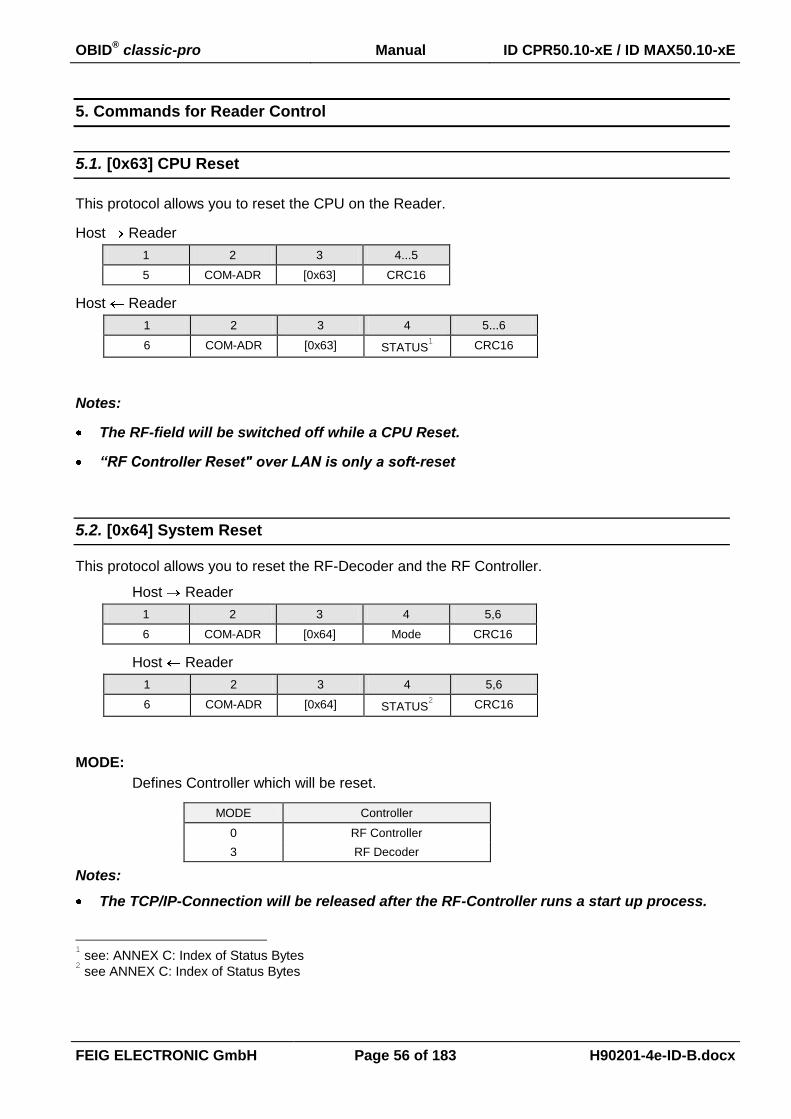
OBID® classic-pro Manual ID CPR50.10-xE / ID MAX50.10-xE
FEIG ELECTRONIC GmbH Page 56 of 183 H90201-4e-ID-B.docx
5. Commands for Reader Control
5.1. [0x63] CPU Reset
This protocol allows you to reset the CPU on the Reader.
Host Reader
1 2 3 4...5
5 COM-ADR [0x63] CRC16
Host Reader
1 2 3 4 5...6
6 COM-ADR [0x63] STATUS1 CRC16
Notes:
The RF-field will be switched off while a CPU Reset.
“RF Controller Reset" over LAN is only a soft-reset
5.2. [0x64] System Reset
This protocol allows you to reset the RF-Decoder and the RF Controller.
Host Reader
1 2 3 4 5,6
6 COM-ADR [0x64] Mode CRC16
Host Reader
1 2 3 4 5,6
6 COM-ADR [0x64] STATUS2 CRC16
MODE:
Defines Controller which will be reset.
MODE Controller
0 RF Controller
3 RF Decoder
Notes:
The TCP/IP-Connection will be released after the RF-Controller runs a start up process.
1 see: ANNEX C: Index of Status Bytes 2 see ANNEX C: Index of Status Bytes

OBID® classic-pro Manual ID CPR50.10-xE / ID MAX50.10-xE
FEIG ELECTRONIC GmbH Page 57 of 183 H90201-4e-ID-B.docx
5.3. [0x65] Get Software Version
This protocol allows you to determine the software version of the Reader, its type and the types of
the Transponders which are supported by the software.
Host Reader
1 2 3 4...5
5 COM-ADR [0x65] CRC16
Host Reader
1 2 3 4 5...6 7
13 COM-ADR [0x65] STATUS1 SW-REV D-REV
8 9 10...11 12...13 14...15 16...17
HW-TYPE SW-TYPE TR-TYPE RX-BUF TX-BUF CRC16
SW-REV:
Version of the firmware.
D-REV:
Revision status of the firmware.
HW-TYPE:
Displays options configuration pin value (internal use).
SW-TYPE:
Displays the type / model of the Reader
(see: ANNEX B: Codes of Reader Types)
TR-TYPE:
Displays the Transponders supported by the Reader.
Bit: 15 14 13 12 11 10 9 8
Function: - - - - - - - -
Bit: 7 6 5 4 3 2 1 0
Function: - - ISO
14443B
ISO
14443A
ISO
15693
- - -
RX-BUF:
RX-BUF is the maximum receive buffer size of the Reader. If a protocol from the host ex-
1 see: ANNEX C: Index of Status Bytes

OBID® classic-pro Manual ID CPR50.10-xE / ID MAX50.10-xE
FEIG ELECTRONIC GmbH Page 58 of 183 H90201-4e-ID-B.docx
ceed the RX-BUF size the Reader response with error code 0x81 PROTOCOL LENGTH
ERROR.
TX-BUF:
TX-BUF is the maximum transmit buffer size of the Reader. The host has to take in to ac-
count that a response protocol of the Reader can have this length.
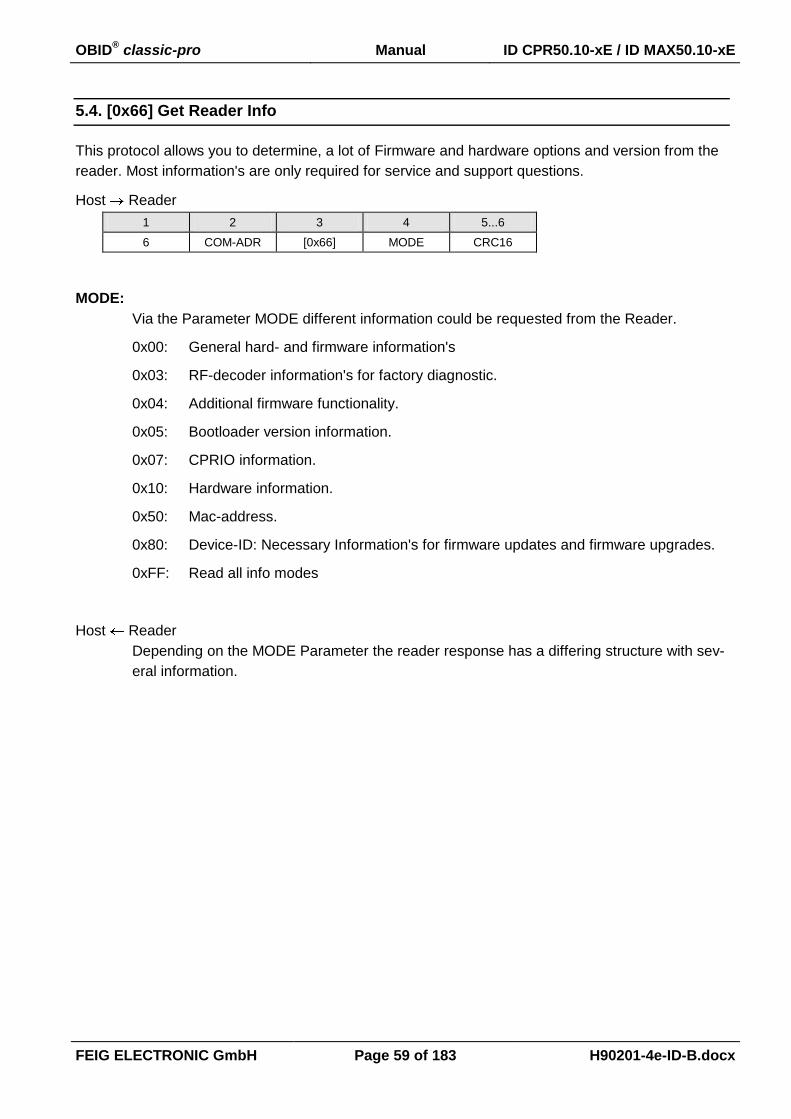
OBID® classic-pro Manual ID CPR50.10-xE / ID MAX50.10-xE
FEIG ELECTRONIC GmbH Page 59 of 183 H90201-4e-ID-B.docx
5.4. [0x66] Get Reader Info
This protocol allows you to determine, a lot of Firmware and hardware options and version from the
reader. Most information's are only required for service and support questions.
Host Reader
1 2 3 4 5...6
6 COM-ADR [0x66] MODE CRC16
MODE:
Via the Parameter MODE different information could be requested from the Reader.
0x00: General hard- and firmware information's
0x03: RF-decoder information's for factory diagnostic.
0x04: Additional firmware functionality.
0x05: Bootloader version information.
0x07: CPRIO information.
0x10: Hardware information.
0x50: Mac-address.
0x80: Device-ID: Necessary Information's for firmware updates and firmware upgrades.
0xFF: Read all info modes
Host Reader
Depending on the MODE Parameter the reader response has a differing structure with sev-
eral information.
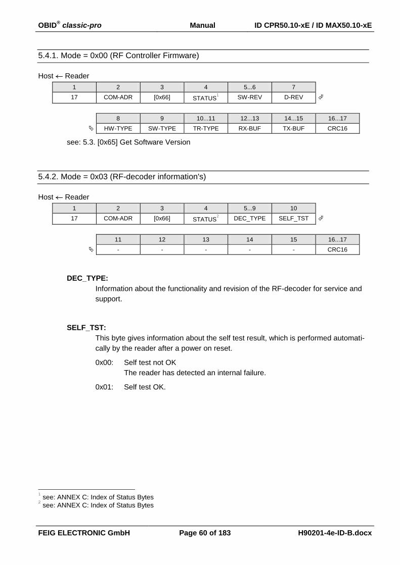
OBID® classic-pro Manual ID CPR50.10-xE / ID MAX50.10-xE
FEIG ELECTRONIC GmbH Page 60 of 183 H90201-4e-ID-B.docx
5.4.1. Mode = 0x00 (RF Controller Firmware)
Host Reader
1 2 3 4 5...6 7
17 COM-ADR [0x66] STATUS1 SW-REV D-REV
8 9 10...11 12...13 14...15 16...17
HW-TYPE SW-TYPE TR-TYPE RX-BUF TX-BUF CRC16
see: 5.3. [0x65] Get Software Version
5.4.2. Mode = 0x03 (RF-decoder information's)
Host Reader
1 2 3 4 5...9 10
17 COM-ADR [0x66] STATUS2 DEC_TYPE SELF_TST
11 12 13 14 15 16...17
- - - - - CRC16
DEC_TYPE:
Information about the functionality and revision of the RF-decoder for service and
support.
SELF_TST:
This byte gives information about the self test result, which is performed automati-
cally by the reader after a power on reset.
0x00: Self test not OK
The reader has detected an internal failure.
0x01: Self test OK.
1 see: ANNEX C: Index of Status Bytes 2 see: ANNEX C: Index of Status Bytes
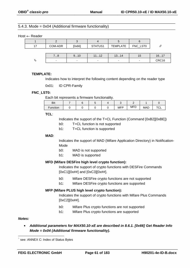
OBID® classic-pro Manual ID CPR50.10-xE / ID MAX50.10-xE
FEIG ELECTRONIC GmbH Page 61 of 183 H90201-4e-ID-B.docx
5.4.3. Mode = 0x04 (Additional firmware functionality)
Host Reader
1 2 3 4 5 6
17 COM-ADR [0x66] STATUS1 TEMPLATE FNC_LST0
7...8 9...10 11...12 13...14 15 16...17
- - - - - CRC16
TEMPLATE:
Indicates how to interpret the following content depending on the reader type
0x01: ID CPR-Family
FNC_LST0:
Each bit represents a firmware functionality.
Bit: 7 6 5 4 3 2 1 0
Function 0 0 0 0 MFP MFD MAD TCL
TCL:
Indicates the support of the T=CL Function (Command [0xB2][0xBE])
b0: T=CL function is not supported
b1: T=CL function is supported
MAD:
Indicates the support of MAD (Mifare Application Directory) in Notification-
Mode
b0: MAD is not supported
b1: MAD is supported
MFD (Mifare DESFire high level crypto function):
Indicates the support of crypto functions with DESFire Commands
[0xC1][0x##] and [0xC3][0x##].
b0: Mifare DESFire crypto functions are not supported
b1: Mifare DESFire crypto functions are supported
MFP (Mifare PLUS high level crypto function):
Indicates the support of crypto functions with Mifare Plus Commands
[0xC2][0x##].
b0: Mifare Plus crypto functions are not supported
b1: Mifare Plus crypto functions are supported
Notes:
Additional parameters for MAX50.10-xE are described in 8.6.1. [0x66] Get Reader Info
Mode = 0x04 (Additional firmware functionality).
1 see: ANNEX C: Index of Status Bytes

OBID® classic-pro Manual ID CPR50.10-xE / ID MAX50.10-xE
FEIG ELECTRONIC GmbH Page 62 of 183 H90201-4e-ID-B.docx
5.4.4. Mode = 0x05 (Bootloader version information)
Host Reader
1 2 3 4 5 6
17 COM-ADR [0x66] STATUS1 BL_VERSION BL_REF
7...8 8...10 1...12 13...14 15 16...17
- - - - - CRC16
BL_VERSION:
Bootloader Version
BL_REV:
Revision of Bootloader Version
1 see: ANNEX C: Index of Status Bytes
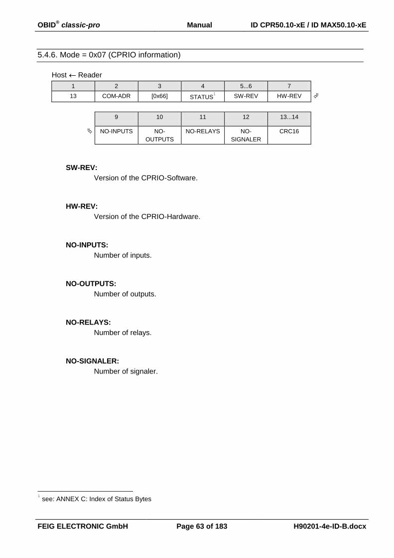
OBID® classic-pro Manual ID CPR50.10-xE / ID MAX50.10-xE
FEIG ELECTRONIC GmbH Page 63 of 183 H90201-4e-ID-B.docx
5.4.6. Mode = 0x07 (CPRIO information)
Host Reader
1 2 3 4 5...6 7
13 COM-ADR [0x66] STATUS1 SW-REV HW-REV
9 10 11 12 13...14
NO-INPUTS NO-
OUTPUTS
NO-RELAYS NO-
SIGNALER
CRC16
SW-REV:
Version of the CPRIO-Software.
HW-REV:
Version of the CPRIO-Hardware.
NO-INPUTS:
Number of inputs.
NO-OUTPUTS:
Number of outputs.
NO-RELAYS:
Number of relays.
NO-SIGNALER:
Number of signaler.
1 see: ANNEX C: Index of Status Bytes

OBID® classic-pro Manual ID CPR50.10-xE / ID MAX50.10-xE
FEIG ELECTRONIC GmbH Page 64 of 183 H90201-4e-ID-B.docx
5.4.7. Mode = 0x10 (Hardware information)
Host Reader
1 2 3 4 5 6 7…8
0x02 19 COM-ADR [0x66] STATUS HW-INFO
9…10 11…12 13 14 15 16
D_HW A_HW FREQUENCY PORT_TYPE reserved RFC-INFO
17 18,19
reserved CRC16
HW-INFO:
Hardware Information
Bit: 15 14 13 12 11 10 9 8
Function: - - - - - - - -
Bit: 7 6 5 4 3 2 1 0
Function: ANT - - - - - - -
ANT:
b0: External antenna.
b1: Internal antenna.
D-HW:
internal use
A-HW:
internal use
FREQUENCY:
Flags for supported frequencies
Bit: 7 6 5 4 3 2 1 0
Function: HF - - - - - - -
HF: b0: HF not supported
b1: HF supported

OBID® classic-pro Manual ID CPR50.10-xE / ID MAX50.10-xE
FEIG ELECTRONIC GmbH Page 65 of 183 H90201-4e-ID-B.docx
PORT_TYPE:
Flags for supported communication ports
Bit: 7 6 5 4 3 2 1 0
Function: - - BT USB WLAN LAN RS4xx RS232
RS232: b0: not supported
b1: supported
RS4xx: b0: not supported
b1: supported
LAN: b0: not supported
b1: supported
WLAN: b0: not supported
b1: supported
USB: b0: not supported
b1: supported
BT: b0: not supported
b1: supported
RFC-INFO:
Displays options which are supported by the RFC
Bit: 7 6 5 4 3 2 1 0
Function: - - - - - - - XC512
XC512: b0: Controller flash size is 256kB.
b1: Controller flash size is 512kB.

OBID® classic-pro Manual ID CPR50.10-xE / ID MAX50.10-xE
FEIG ELECTRONIC GmbH Page 66 of 183 H90201-4e-ID-B.docx
5.4.9. Mode = 0x50 (MAC-address)
Host Reader
1 2 3 4 5 6..11
13 COM-ADR [0x66] STATUS1 FLAGS MAC
12...13
CRC16
FLAGS:
indicates additional settings
Byte 5
Bit: 7 6 5 4 3 2 1 0
0 0 0 0 0 0 IP V4 0
IP V4:
b0: disabled
b1: enabled
MAC:
MAC-Address of the Reader.
1 see: ANNEX C: Index of Status Bytes
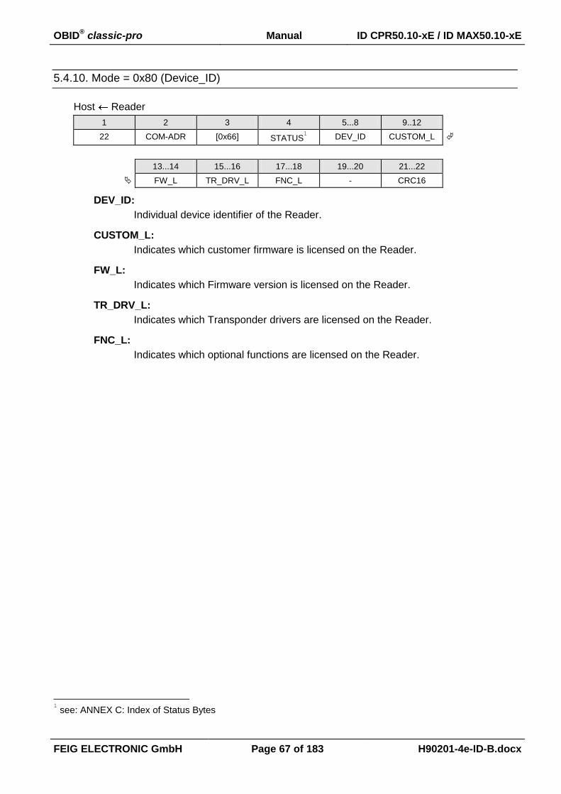
OBID® classic-pro Manual ID CPR50.10-xE / ID MAX50.10-xE
FEIG ELECTRONIC GmbH Page 67 of 183 H90201-4e-ID-B.docx
5.4.10. Mode = 0x80 (Device_ID)
Host Reader
1 2 3 4 5...8 9..12
22 COM-ADR [0x66] STATUS1 DEV_ID CUSTOM_L
13...14 15...16 17...18 19...20 21...22
FW_L TR_DRV_L FNC_L - CRC16
DEV_ID:
Individual device identifier of the Reader.
CUSTOM_L:
Indicates which customer firmware is licensed on the Reader.
FW_L:
Indicates which Firmware version is licensed on the Reader.
TR_DRV_L:
Indicates which Transponder drivers are licensed on the Reader.
FNC_L:
Indicates which optional functions are licensed on the Reader.
1 see: ANNEX C: Index of Status Bytes

OBID® classic-pro Manual ID CPR50.10-xE / ID MAX50.10-xE
FEIG ELECTRONIC GmbH Page 68 of 183 H90201-4e-ID-B.docx
5.4.11. Mode = 0xFF (All Info Records)
Return of all Info records in one Response.
1 2 3 4 5
9 COM-ADR [0x66] STATUS DATASETS
7 8..37 2 Byte
MODE DATA CRC16
Repeated DATASETS times
MODE:
Mode byte
DATA:
Data record according the definition in previous sections.
The data record is always 30 byte long and information begins always with byte 0,
Unused bytes must be filled with 0x00.

OBID® classic-pro Manual ID CPR50.10-xE / ID MAX50.10-xE
FEIG ELECTRONIC GmbH Page 69 of 183 H90201-4e-ID-B.docx
5.5. [0x69] RF Reset
The RF-field of the Reader antenna can be switched off for trf = 15 ms by the command RF Reset.
Thus, all Transponders which are within the antenna field of the Reader will be reset to their base
setting.
Host Reader
1 2 3 4,5
5 COM-ADR [0x69] CRC16
Host Reader
1 2 3 4 5,6
6 COM-ADR [0x69] STATUS1 CRC16
Notes:
After the RF Reset command the Reader is not able to receive any new Transponder be-
fore expiration of trf .
After a RF Reset a Transponder which is located within the field has to be re-selected.
1 see: ANNEX C: Index of Status Bytes

OBID® classic-pro Manual ID CPR50.10-xE / ID MAX50.10-xE
FEIG ELECTRONIC GmbH Page 70 of 183 H90201-4e-ID-B.docx
5.6. [0x6A] RF Output ON/OFF
The command RF ON/OFF switches the RF field of the Reader antenna ON or OFF.
Host Reader
1 2 3 4 5,6
6 COM-ADR [0x6A] RF_OUTPUT CRC16
Host Reader
1 2 3 4 5,6
6 COM-ADR [0x6A] STATUS1 CRC16
RF_OUTPUT:
Set on of the antenna outputs.
Bit: 7 6 5 4 3 2 1 0
Function SNFM 0 0 0 0 ANT
SNFM:
With this bit the notification mode can be suspended temporary, e.g. to exchange
data with a transponder in polling mode. This bit has only effect if the notification
mode is enabled (see: 3.2. CFG1: Interface, READER-MODE)
b0: Reactivates the suspended notification mode
b1 Suspends the notification mode while it is reactivated by setting SNFM =
b0
NOTICE:
In each case the ANT has to be set to b001 otherwise the antenna will be
switched off!
ANT:
This parameter could be used to select one antenna.
b000: switches off RF power at all antennas.
b001: switches on the RF power at antenna 1.
This setting is to use, if the reader has only one internal or one external
antenna.
NOTICE:
If there are no 6. ISO Host Commands for Transponder Communication send within 20 sec.
the antenna will be switched off again automatically.
1 see ANNEX C: Index of Status Bytes

OBID® classic-pro Manual ID CPR50.10-xE / ID MAX50.10-xE
FEIG ELECTRONIC GmbH Page 71 of 183 H90201-4e-ID-B.docx
5.7. [0x72] Set Output
The command Set Output serves temporary limited or unlimited activation of the outputs of the
Reader.
Each output takes on the state defined by the byte OUTx-mode for the period of time (OUT-TIME)
included in the protocol. Via this protocol the outputs can be switched on or off for the indicated pe-
riod of time. If the Reader receives a command Set Output, all times that have been active until then
are being overwritten by the new times included in the protocol if they are 0.
Host Reader
1 2 3 4 5
n COM-ADR [0x72] Mode OUT-N
6 7 8-9 n-1...n
OUT-NR OUT-S OUT-TIME CRC16
Repeated OUT-N times
Host Reader
1 2 3 4 5...6
6 COM-ADR [0x71] STATUS CRC16
Mode: 0x00
OUT-N:
Defines the number of output records.
OUT-NR:
Defines the type and the number of the output
Bit: 7 6 5 4 3 2 1 0
Function: OUT-Typ 0 OUT-Number
OUT-Typ:
b001 LED
b010 Buzzer
b100 Relay
any other bit configuration is reserved
OUT-Number (for OUT-Typ LED):
b0001 LED1 (green)
b0010 LED2 (blue)
b0011 LED3 (red)
Notes:
For OUT-Typ Buzzer and Relay the OUT-Number must be b0001.

OBID® classic-pro Manual ID CPR50.10-xE / ID MAX50.10-xE
FEIG ELECTRONIC GmbH Page 72 of 183 H90201-4e-ID-B.docx
OUT-S:
OUT-S (Output State) defines the status of the output during the time defined in OUT-TIME
and provides the possibility to allocate its own flashing-frequency to each output.
Bit: 7 6 5 4 3 2 1 0
Function: 0 0 0 0 0 0 OUTx-mode
OUTx-mode:
b00: OFF
b01: ON
b10: FLASHING SLOW
b11: FLASHING FAST
OUT-TIME:
By the values defined by “OUT-TIME” the outputs can be activated temporary limited or un-
limited.
Accepted are the time values 0 and 65535 (0xFFFF) (see following table).
0x0001 1 x 100ms -> 100ms
... ...
0xFFFE 65534 x 100ms -> 1:49:13 h
0xFFFF continuously active
Notes:
In order to reset a continuously active time, OUT-TIME = 1 has to be sent to the
Reader, which effects a change to the idle status after 100 ms.
The continuous activation is being set back after a reset or a power failure.
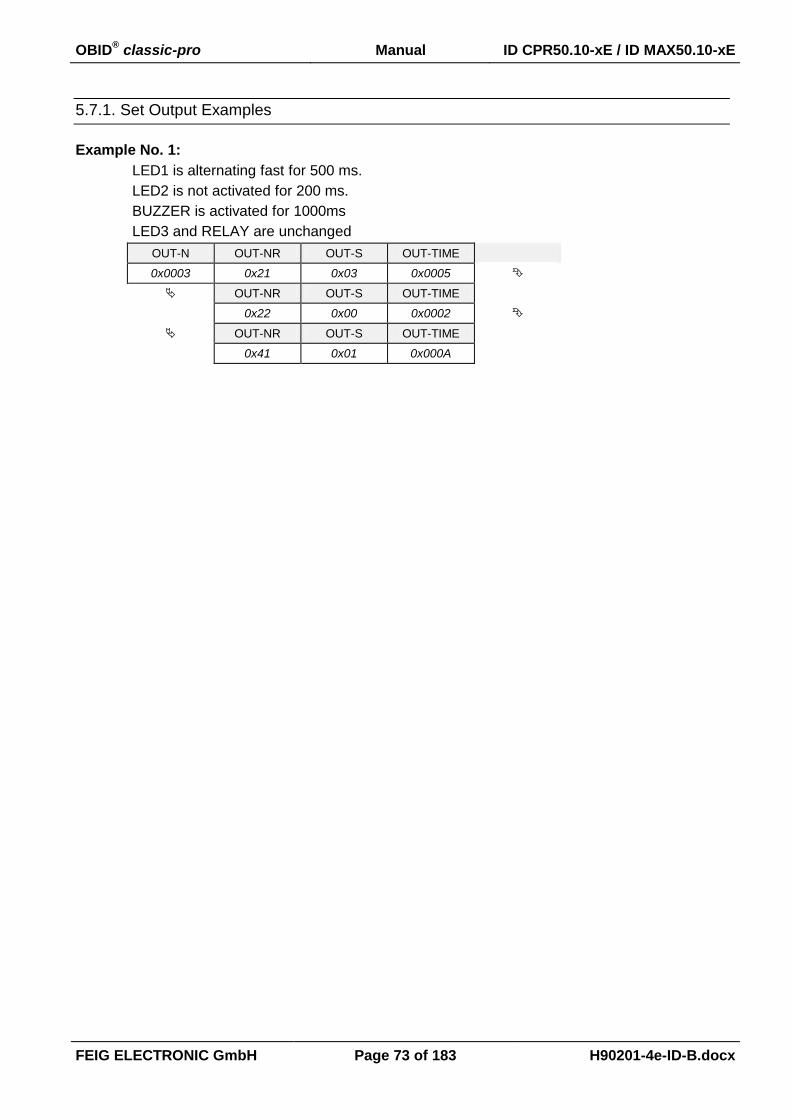
OBID® classic-pro Manual ID CPR50.10-xE / ID MAX50.10-xE
FEIG ELECTRONIC GmbH Page 73 of 183 H90201-4e-ID-B.docx
5.7.1. Set Output Examples
Example No. 1:
LED1 is alternating fast for 500 ms.
LED2 is not activated for 200 ms.
BUZZER is activated for 1000ms
LED3 and RELAY are unchanged
OUT-N OUT-NR OUT-S OUT-TIME
0x0003 0x21 0x03 0x0005
OUT-NR OUT-S OUT-TIME
0x22 0x00 0x0002
OUT-NR OUT-S OUT-TIME
0x41 0x01 0x000A
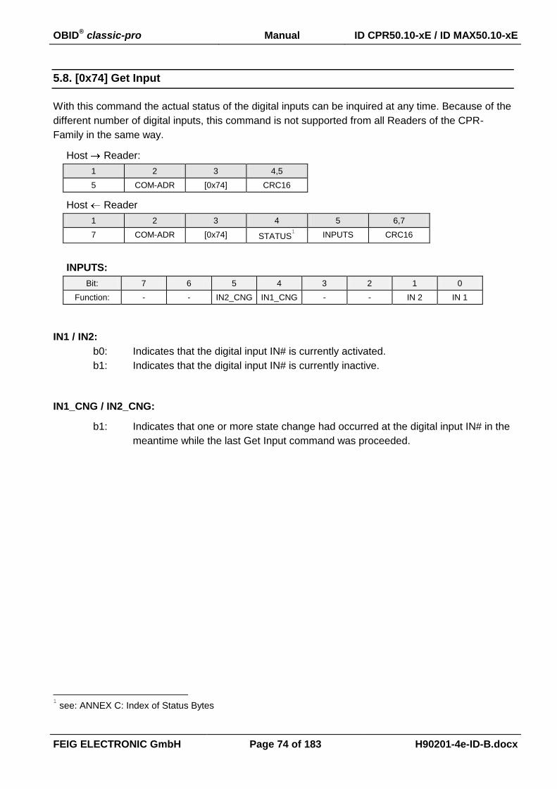
OBID® classic-pro Manual ID CPR50.10-xE / ID MAX50.10-xE
FEIG ELECTRONIC GmbH Page 74 of 183 H90201-4e-ID-B.docx
5.8. [0x74] Get Input
With this command the actual status of the digital inputs can be inquired at any time. Because of the
different number of digital inputs, this command is not supported from all Readers of the CPR-
Family in the same way.
Host Reader:
1 2 3 4,5
5 COM-ADR [0x74] CRC16
Host Reader
1 2 3 4 5 6,7
7 COM-ADR [0x74] STATUS1 INPUTS CRC16
INPUTS:
Bit: 7 6 5 4 3 2 1 0
Function: - - IN2_CNG IN1_CNG - - IN 2 IN 1
IN1 / IN2:
b0: Indicates that the digital input IN# is currently activated.
b1: Indicates that the digital input IN# is currently inactive.
IN1_CNG / IN2_CNG:
b1: Indicates that one or more state change had occurred at the digital input IN# in the
meantime while the last Get Input command was proceeded.
1 see: ANNEX C: Index of Status Bytes

OBID® classic-pro Manual ID CPR50.10-xE / ID MAX50.10-xE
FEIG ELECTRONIC GmbH Page 75 of 183 H90201-4e-ID-B.docx
5.9. [0xAE] Reader Authent
This command starts the mutual three-path authentication process. The key can be configured with
command 4.7. [0xAD] Write Reader Authent-Key.
Host Reader
1-3 4 5 6 7 8…n-2 n-1, n
0x02 + LEN COM-ADR 0xAE MODE KEY-TYPE DATA CRC16
Host Reader
1-3 4 5 6 7…n-2 n-1, n
0x02 + LEN COM-ADR 0xAE STATUS DATA CRC16
MODE: (RFU)
Bit: 7 6 5 4 3 2 1 0
Function 0 0 0 0 0 0 0 0
KEY-TYPE:
Defines the key for the authentication.
0x00 AES 128 Bit
0x01 AES 192 Bit
0x02 AES 256 Bit
DATA:
Data contains a random value (length depends on KEY-TYPE).
NOTE:
This command can be used only with software based on OBID SDK.
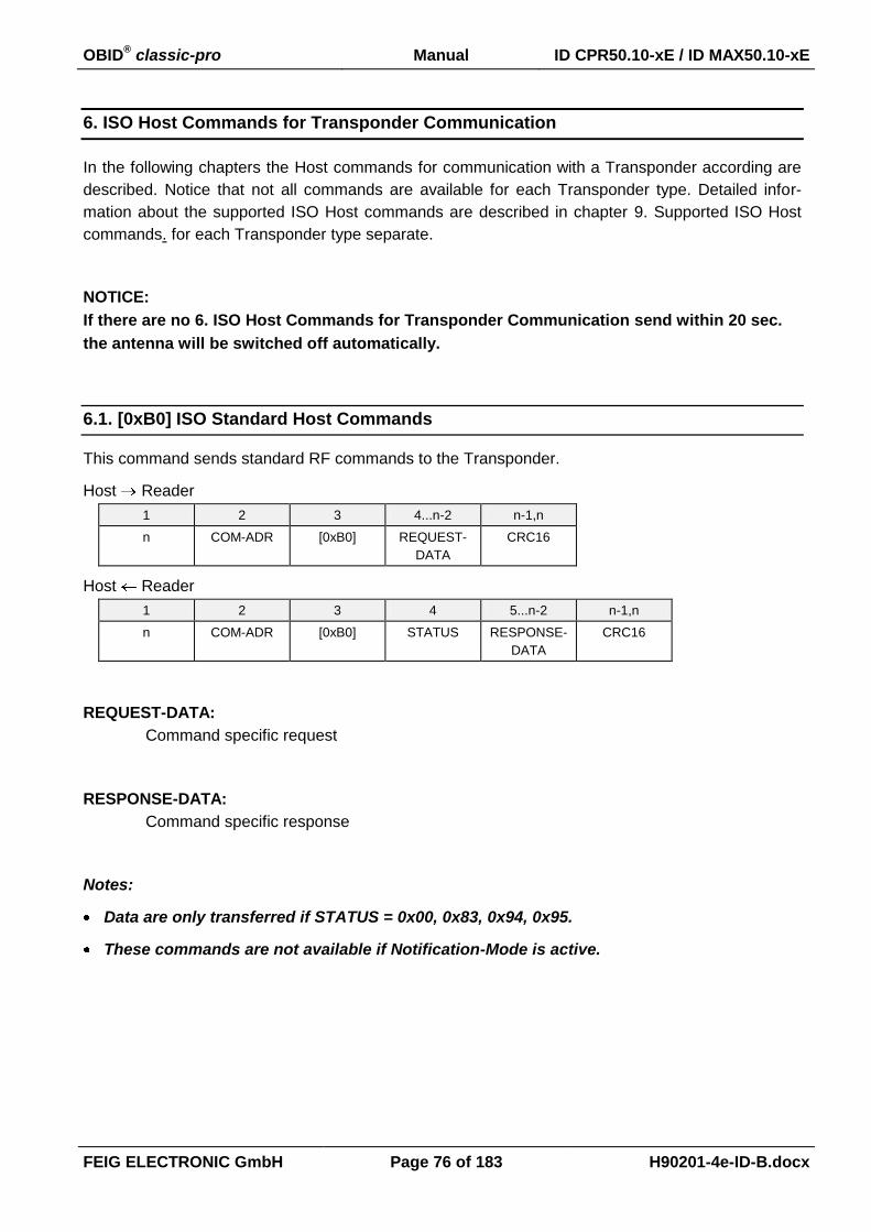
OBID® classic-pro Manual ID CPR50.10-xE / ID MAX50.10-xE
FEIG ELECTRONIC GmbH Page 76 of 183 H90201-4e-ID-B.docx
6. ISO Host Commands for Transponder Communication
In the following chapters the Host commands for communication with a Transponder according are
described. Notice that not all commands are available for each Transponder type. Detailed infor-
mation about the supported ISO Host commands are described in chapter 9. Supported ISO Host
commands. for each Transponder type separate.
NOTICE:
If there are no 6. ISO Host Commands for Transponder Communication send within 20 sec.
the antenna will be switched off automatically.
6.1. [0xB0] ISO Standard Host Commands
This command sends standard RF commands to the Transponder.
Host Reader
1 2 3 4...n-2 n-1,n
n COM-ADR [0xB0] REQUEST-
DATA
CRC16
Host Reader
1 2 3 4 5...n-2 n-1,n
n COM-ADR [0xB0] STATUS RESPONSE-
DATA
CRC16
REQUEST-DATA:
Command specific request
RESPONSE-DATA:
Command specific response
Notes:
Data are only transferred if STATUS = 0x00, 0x83, 0x94, 0x95.
These commands are not available if Notification-Mode is active.

OBID® classic-pro Manual ID CPR50.10-xE / ID MAX50.10-xE
FEIG ELECTRONIC GmbH Page 77 of 183 H90201-4e-ID-B.docx
6.1.1. [0x01] Inventory
This command reads the UID of all Transponders inside the detection range. The reply behavior of
this command can be configured by the ONT parameter of configuration block 3.6. CFG5:
Anticollision.
REQUEST-DATA
4 5 6
[0x01] MODE [0x00]
RESPONSE-DATA see: 6.1.1.1. Response-Data - ISO 14443A (TR-TYPE = 0x04)
6.1.1.2. Response-Data - ISO 14443B (TR-TYPE = 0x05)
6.1.1.3. Response-Data - ISO 15693 (TR-TYPE = 0x03)
MODE:
Bit: 7 6 5 4 3 2 1 0
Function MORE - - - - - - -
MORE:
this bit can be used, to read out the whole UIDs, after the Reader had signalized
more data sets with status 0x94 (see: ANNEX C: Index of Status Bytes).
b0: new Inventory requested
The reader carries out a new inquiry, which Transponder are in his detec-
tion range.
b1: more data requested
The reader response contain the UIDs which are not transferred with the
last response because of the status 0x94.
DATA-SETS:
Number of Transponder data sets to be transferred in this reader response.
TR-TYPE:
Bit: 7 6 5 4 3 2 1 0
Function RF_TEC - - TYPE_NO
RF_TEC:
Indicates the RFID - Technology of the present Transponder:
b00: 13,56 MHz Transponder
b10: UHF Transponder

OBID® classic-pro Manual ID CPR50.10-xE / ID MAX50.10-xE
FEIG ELECTRONIC GmbH Page 78 of 183 H90201-4e-ID-B.docx
TYPE_NO:
Displays the Transponder type of the present Transponder
(see: ANNEX A: Codes of Transponder Types).
RESPONSE-DATA:
Depending on the Transponder type the response data of the Reader are different as de-
scribed in the following chapters.
6.1.1.1. Response-Data - ISO 14443A (TR-TYPE = 0x04)
Response data of ISO 14443 Type A compliant Transponder:
Case CFG3. ISO14443 FTUR.OPTI = b0 OPT_INFO is disabled
5 6 7 8 9...15 (18)
DATA-SETS TR-TYPE TR_INFO 0 UID
Repeated DATA-SETS times
Case CFG3. ISO14443 FTUR.OPTI = b1 OPT_INFO is enabled
5 6 7 8 9...15 (18)
DATA-SETS TR-TYPE TR_INFO OPT_INFO UID
Repeated DATA-SETS times
TR_INFO (only ISO 14443A Transponder):
This byte represents some information's from the SAK byte as described in ISO14443-31.
Bit: 7 6 5 4 3 2 1 0
Function - - L4 - - CL3 - -
CL3: Displays the UID length of the present Transponder.
b0 The UID is transmitted as a 7 byte field
(Transponder with Cascade Level 1 or Level 2)
b1 The UID is transmitted as a 10 byte field
(Transponder with Cascade Level 3)
L4: Displays the compliance of the Transponder with ISO 14443-4 according
ISO 14443-3, SAK, b6
b0 Not compliant with ISO 14443-4
b1 Compliant with ISO 14443-4
1 In case of NXP mifare chips this byte also indicates the chip type. Further information's are given in the NXP Application Note "mifare Interface Platform, Type Identification Procedure" M018412.
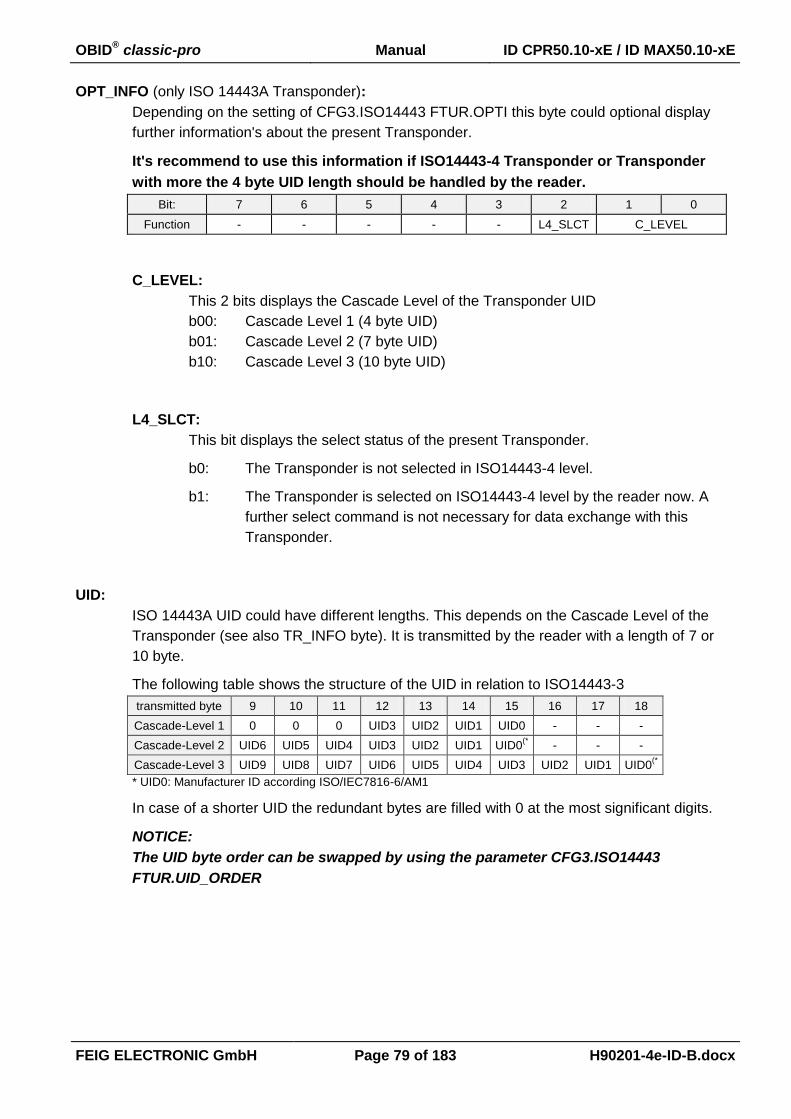
OBID® classic-pro Manual ID CPR50.10-xE / ID MAX50.10-xE
FEIG ELECTRONIC GmbH Page 79 of 183 H90201-4e-ID-B.docx
OPT_INFO (only ISO 14443A Transponder):
Depending on the setting of CFG3.ISO14443 FTUR.OPTI this byte could optional display
further information's about the present Transponder.
It's recommend to use this information if ISO14443-4 Transponder or Transponder
with more the 4 byte UID length should be handled by the reader.
Bit: 7 6 5 4 3 2 1 0
Function - - - - - L4_SLCT C_LEVEL
C_LEVEL:
This 2 bits displays the Cascade Level of the Transponder UID
b00: Cascade Level 1 (4 byte UID)
b01: Cascade Level 2 (7 byte UID)
b10: Cascade Level 3 (10 byte UID)
L4_SLCT:
This bit displays the select status of the present Transponder.
b0: The Transponder is not selected in ISO14443-4 level.
b1: The Transponder is selected on ISO14443-4 level by the reader now. A
further select command is not necessary for data exchange with this
Transponder.
UID:
ISO 14443A UID could have different lengths. This depends on the Cascade Level of the
Transponder (see also TR_INFO byte). It is transmitted by the reader with a length of 7 or
10 byte.
The following table shows the structure of the UID in relation to ISO14443-3
transmitted byte 9 10 11 12 13 14 15 16 17 18
Cascade-Level 1 0 0 0 UID3 UID2 UID1 UID0 - - -
Cascade-Level 2 UID6 UID5 UID4 UID3 UID2 UID1 UID0(* - - -
Cascade-Level 3 UID9 UID8 UID7 UID6 UID5 UID4 UID3 UID2 UID1 UID0(*
* UID0: Manufacturer ID according ISO/IEC7816-6/AM1
In case of a shorter UID the redundant bytes are filled with 0 at the most significant digits.
NOTICE:
The UID byte order can be swapped by using the parameter CFG3.ISO14443
FTUR.UID_ORDER

OBID® classic-pro Manual ID CPR50.10-xE / ID MAX50.10-xE
FEIG ELECTRONIC GmbH Page 80 of 183 H90201-4e-ID-B.docx
6.1.1.2. Response-Data - ISO 14443B (TR-TYPE = 0x05)
Response data of ISO 14443 Type B compliant Transponder:
5 6 7 8...11 12...15
DATA-SETS TR-TYPE PROTO
INFO.
APP DATA PUPI
Repeated DATA-SETS times
PUPI:
4 byte Pseudo-Unique PICC Identifier, according ISO 14443-3:2001.
This information is required to select the Transponder.
APP_DATA:
4 byte Application Date according ISO 14443-3:2001.
1 2 3 4
AFI CRC_B (AID) Number of
Applications
PROTO_INFO:
This parameter is extracted from the protocol Info bytes as described in ISO14443-3.
Bit: 7 6 5 4 3 2 1 0
Function Max_Frame_Size Protocol_Type
Max_Frame_Size (according ISO14443-3:2001):
Value 0 1 2 3 4 5 6 7 8 9-F
Frame Size (Byte) 16 24 32 40 48 64 96 128 256 RFU > 256
Protocol_Type (according ISO14443-3:2001):
7 6 5 4 Meaning
0 0 0 1 PICC compliant with ISO/IEC 14443-4
0 0 0 0 PICC not compliant with ISO/IEC 14443-4

OBID® classic-pro Manual ID CPR50.10-xE / ID MAX50.10-xE
FEIG ELECTRONIC GmbH Page 81 of 183 H90201-4e-ID-B.docx
6.1.1.3. Response-Data - ISO 15693 (TR-TYPE = 0x03)
Response data of ISO 15693 compliant Transponder:
RESPONSE-DATA (standard)
5 6 7 8...15
DATA-SETS TR-TYPE DSFID UID
Repeated DATA-SETS times
DATA-SETS:
Number of Transponder data sets to be transferred in this Reader response.
TR-TYPE:
Bit: 7 6 5 4 3 2 1 0
Function RF_TEC - - TYPE_NO
RF_TEC:
Indicates the RFID - Technology of the present Transponder:
b00: 13,56 MHz Transponder
TYPE_NO
Displays the Transponder type of the present Transponder
(see: ANNEX A: Codes of Transponder Types).
DSFID: (only ISO15693Transponders)
Data Storage Family Identifier.
UID:
ISO 156963 UID. It is transmitted by the reader with a length of 8 byte.

OBID® classic-pro Manual ID CPR50.10-xE / ID MAX50.10-xE
FEIG ELECTRONIC GmbH Page 82 of 183 H90201-4e-ID-B.docx
6.1.1.5. Sequences of Inventory Command and ISO14443 Transponder
The following chart displays the sequences and effects after a Inventory command depending on
the Transponder type and the Reader configurations.
Transponder(s)
are selected
No of
announced
Transponder
next possible commands
Response 1 no > 1 (possibly) 6.1.2. [0x25] Select
Response 2
yes
one Transponder
on ISO14443-3 level
1
Proprietary or standard commands for
ISO14443 Transponders
(see 6.4. [0xB2] ISO14443 Special Host Commands)
Response 3
yes
one Transponder
on ISO14443-4 level
1 ISO14443-4 Commands
(see 6.4. [0xB2] ISO14443 Special Host Commands
A n t i c o l l is io n d is a b le d
(C F G 5 . O N T . A C O L L )
IS O 1 4 4 4 3 - 4
s u p p o r e d b y
T r a n s p o n d e r
IS O 1 4 4 4 3 - A
T r a n s p o n d e r
IS O 1 4 4 4 3 - B
T r a n s p o n d e r
[0 x 0 1 ] i n v e n t o r y
R e s p o n s e 1
R e s p o n s e 3
d r i v e r f o r
IS O 1 4 4 4 3 A - 4 e n a b le d ?
(C F G 3 . IS O 1 4 4 4 3 A _ D R V . L 4 )
y e s
y e s
n o
n o
n o
R e s p o n s e 2
y e s
y e s
n o
y e s
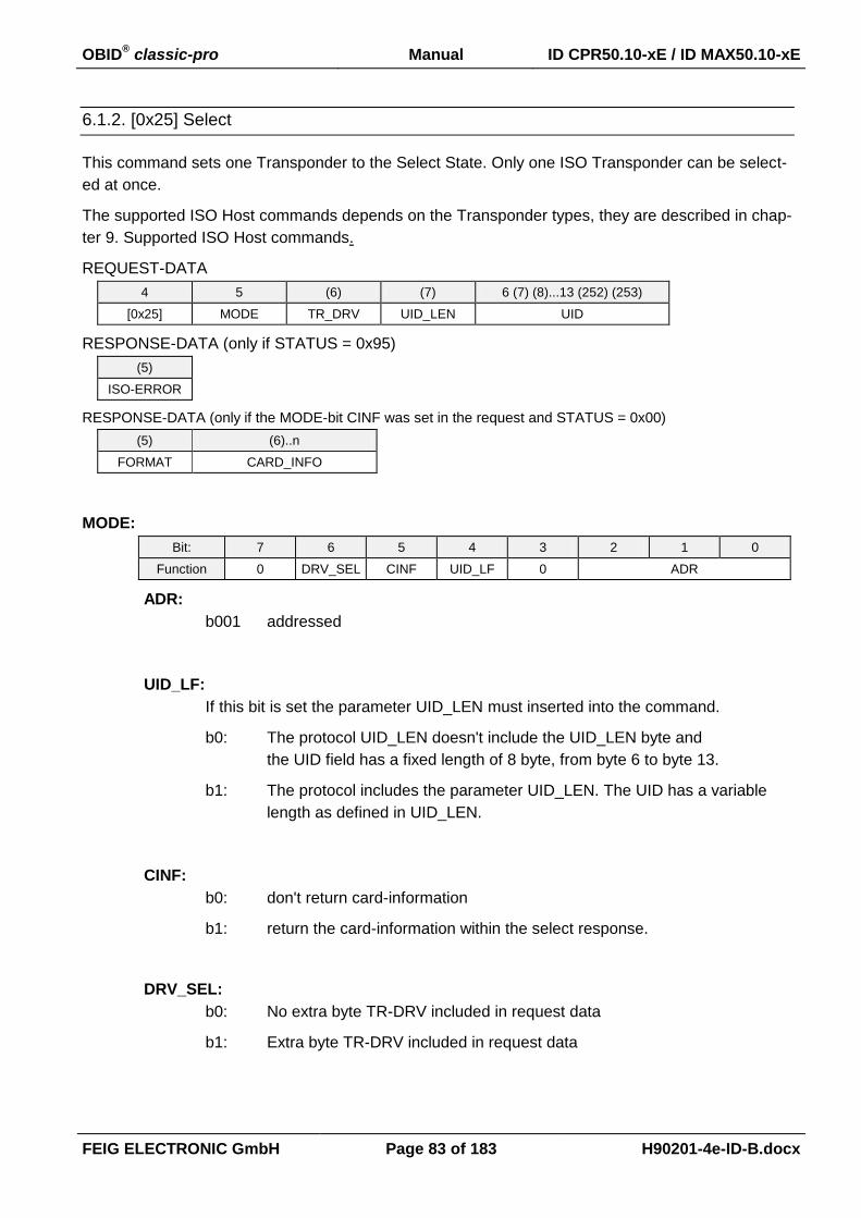
OBID® classic-pro Manual ID CPR50.10-xE / ID MAX50.10-xE
FEIG ELECTRONIC GmbH Page 83 of 183 H90201-4e-ID-B.docx
6.1.2. [0x25] Select
This command sets one Transponder to the Select State. Only one ISO Transponder can be select-
ed at once.
The supported ISO Host commands depends on the Transponder types, they are described in chap-
ter 9. Supported ISO Host commands.
REQUEST-DATA
4 5 (6) (7) 6 (7) (8)...13 (252) (253)
[0x25] MODE TR_DRV UID_LEN UID
RESPONSE-DATA (only if STATUS = 0x95)
(5)
ISO-ERROR
RESPONSE-DATA (only if the MODE-bit CINF was set in the request and STATUS = 0x00)
(5) (6)..n
FORMAT CARD_INFO
MODE:
Bit: 7 6 5 4 3 2 1 0
Function 0 DRV_SEL CINF UID_LF 0 ADR
ADR:
b001 addressed
UID_LF:
If this bit is set the parameter UID_LEN must inserted into the command.
b0: The protocol UID_LEN doesn't include the UID_LEN byte and
the UID field has a fixed length of 8 byte, from byte 6 to byte 13.
b1: The protocol includes the parameter UID_LEN. The UID has a variable
length as defined in UID_LEN.
CINF:
b0: don't return card-information
b1: return the card-information within the select response.
DRV_SEL:
b0: No extra byte TR-DRV included in request data
b1: Extra byte TR-DRV included in request data
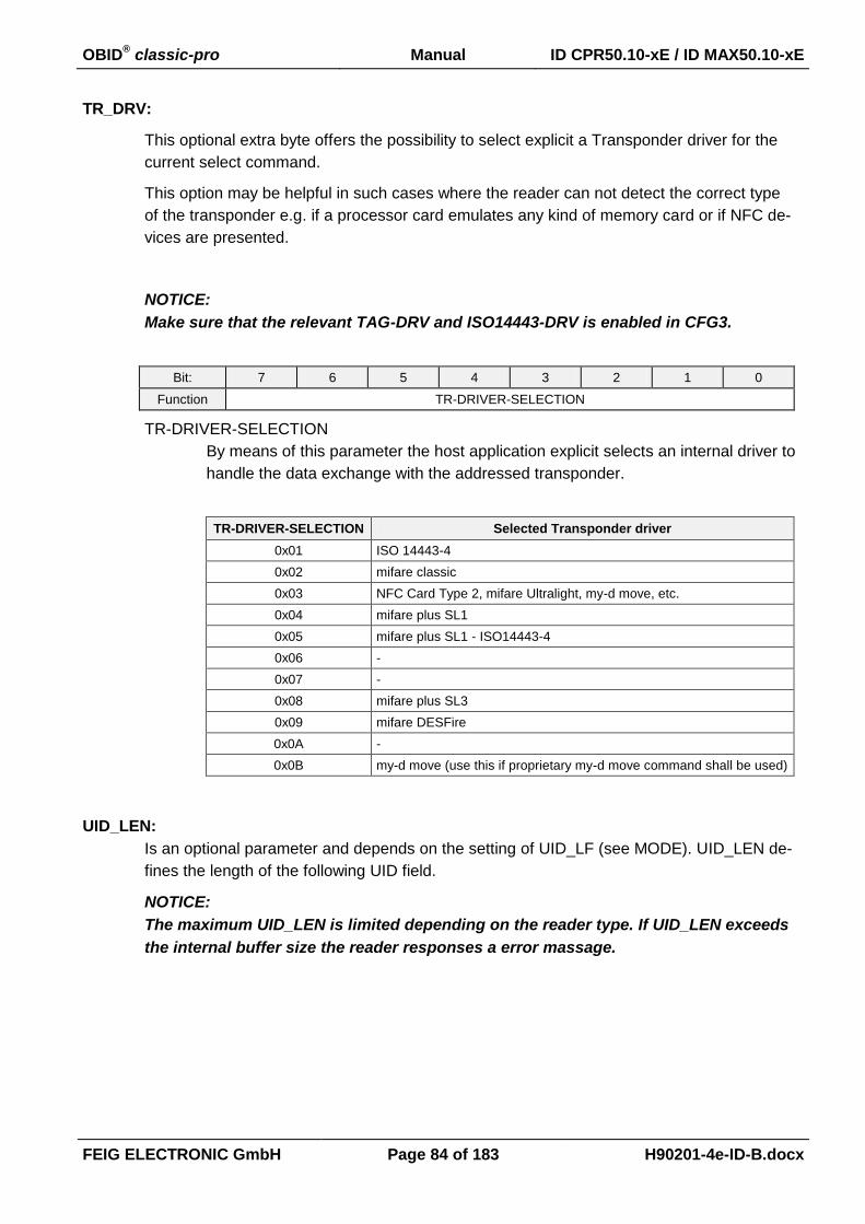
OBID® classic-pro Manual ID CPR50.10-xE / ID MAX50.10-xE
FEIG ELECTRONIC GmbH Page 84 of 183 H90201-4e-ID-B.docx
TR_DRV:
This optional extra byte offers the possibility to select explicit a Transponder driver for the
current select command.
This option may be helpful in such cases where the reader can not detect the correct type
of the transponder e.g. if a processor card emulates any kind of memory card or if NFC de-
vices are presented.
NOTICE:
Make sure that the relevant TAG-DRV and ISO14443-DRV is enabled in CFG3.
Bit: 7 6 5 4 3 2 1 0
Function TR-DRIVER-SELECTION
TR-DRIVER-SELECTION
By means of this parameter the host application explicit selects an internal driver to
handle the data exchange with the addressed transponder.
TR-DRIVER-SELECTION Selected Transponder driver
0x01 ISO 14443-4
0x02 mifare classic
0x03 NFC Card Type 2, mifare Ultralight, my-d move, etc.
0x04 mifare plus SL1
0x05 mifare plus SL1 - ISO14443-4
0x06 -
0x07 -
0x08 mifare plus SL3
0x09 mifare DESFire
0x0A -
0x0B my-d move (use this if proprietary my-d move command shall be used)
UID_LEN:
Is an optional parameter and depends on the setting of UID_LF (see MODE). UID_LEN de-
fines the length of the following UID field.
NOTICE:
The maximum UID_LEN is limited depending on the reader type. If UID_LEN exceeds
the internal buffer size the reader responses a error massage.

OBID® classic-pro Manual ID CPR50.10-xE / ID MAX50.10-xE
FEIG ELECTRONIC GmbH Page 85 of 183 H90201-4e-ID-B.docx
UID:
UID, Serial-Number or pseudo unique identifier of the Transponder.
Depending on the UID_LF and UID_LEN the UID field could have a fixed ore a variable
length and a variable position in the protocol.
case UID_LF = 0:
If UID_LEN is not used, the following definitions are mandatory depending on the
Transponder type.
ISO 14443A
4 5 6 8...13
[0x25] b000 0001 0x00 UID
ISO 14443B
4 5 6...9 10...13
[0x25] b000 0001 0x00 PUPI
case : UID_LF = 1
If UID_LEN is activated the specific UID length of the Transponder should be used
in the protocol.
4 5 6 7... 7+UID_LEN
[0x25] MODE UID_LEN UID
ISO-ERROR:
Additional error code if STATUS = 0x95.
FORMAT:
Indicates the format of the CARD_INFO field:
0x00: No further CARD_INFO field available.
0x01: CARD_INFO of an ISO14443-4 Type-A Transponder.
0x02: CARD_INFO of an ISO14443-4 Type-B Transponder.
0x03: CARD_INFO of an ISO14443-3 Type-A Transponder.

OBID® classic-pro Manual ID CPR50.10-xE / ID MAX50.10-xE
FEIG ELECTRONIC GmbH Page 86 of 183 H90201-4e-ID-B.docx
CARD_INFO:
Depending on the FORMAT parameter this data field contains different data's
case FORMAT = 0x01
CARD_INFO contains the ATQA and SAK and parts of the Answer to select (ATS)
of the ISO14443 Type-A Transponder as defined in ISO14443-4. The length of
CARD_INFO depends on the TL parameter. The response length depends on the
TL parameter of the Transponder ATS.
6 7
ATQA
RFU Proprietary coding UID size RFU Bit frame anticollision
8 9
SAK TL
(10....10+TL-2)
T0, TA(1), TB(1), TC(1) T1, Tk
case FORMAT = 0x02
CARD_INFO contains parts of the answer ATQB response ATTRIB response of
the ISO14443 Type-B Transponder as defined in ISO14443-3.
6 7 8
ATQB Response Protocol Info
Bit_Rate_capability Max_Frame_
Size
Protocol_Type FWI ADC F0
9
1 th Byte of Answer to ATTRIB
MBLI CID
case FORMAT = 0x03
CARD_INFO contains the ATQA and SAK parameter after the anticollision loop
has finished of ISO14443 Type-A Transponder as defined in ISO14443-3.
6 7
ATQA
RFU Proprietary coding UID size RFU Bit frame anticollision
8
SAK
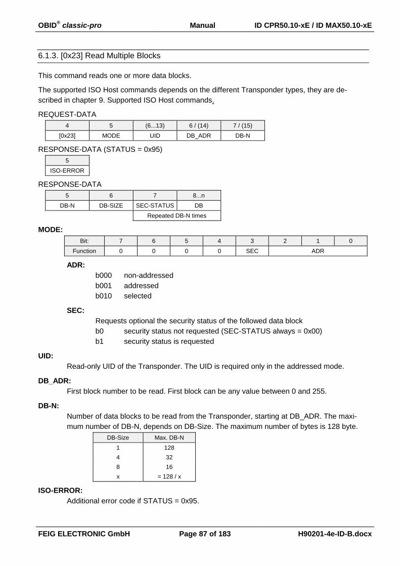
OBID® classic-pro Manual ID CPR50.10-xE / ID MAX50.10-xE
FEIG ELECTRONIC GmbH Page 87 of 183 H90201-4e-ID-B.docx
6.1.3. [0x23] Read Multiple Blocks
This command reads one or more data blocks.
The supported ISO Host commands depends on the different Transponder types, they are de-
scribed in chapter 9. Supported ISO Host commands.
REQUEST-DATA
4 5 (6...13) 6 / (14) 7 / (15)
[0x23] MODE UID DB_ADR DB-N
RESPONSE-DATA (STATUS = 0x95)
5
ISO-ERROR
RESPONSE-DATA
5 6 7 8...n
DB-N DB-SIZE SEC-STATUS DB
Repeated DB-N times
MODE:
Bit: 7 6 5 4 3 2 1 0
Function 0 0 0 0 SEC ADR
ADR:
b000 non-addressed
b001 addressed
b010 selected
SEC:
Requests optional the security status of the followed data block
b0 security status not requested (SEC-STATUS always = 0x00)
b1 security status is requested
UID:
Read-only UID of the Transponder. The UID is required only in the addressed mode.
DB_ADR:
First block number to be read. First block can be any value between 0 and 255.
DB-N:
Number of data blocks to be read from the Transponder, starting at DB_ADR. The maxi-
mum number of DB-N, depends on DB-Size. The maximum number of bytes is 128 byte.
DB-Size Max. DB-N
1 128
4 32
8 16
x = 128 / x
ISO-ERROR:
Additional error code if STATUS = 0x95.
OBID® classic-pro Manual ID CPR50.10-xE / ID MAX50.10-xE
FEIG ELECTRONIC GmbH Page 88 of 183 H90201-4e-ID-B.docx
DB-SIZE:
Number of bytes of one data block. This value depends on the specification of the Tran-
sponder manufacturer, see chapter 9. Supported ISO Host commands.
SEC-STATUS:
Block security status of followed data block.
If SEC-STATUS is not requested or not supported, this value will return 0x00.
DB:
Requested data block. The block size is defined by DB-SIZE.
Notes:
A read from 1 block uses a Read Single Block command to the Transponder.
If a Transponder does not support Read Multiple Blocks commands several Read Single
Block commands are used for this Transponder.
Only one Transponder can be read in the non-addressed mode.

OBID® classic-pro Manual ID CPR50.10-xE / ID MAX50.10-xE
FEIG ELECTRONIC GmbH Page 89 of 183 H90201-4e-ID-B.docx
6.1.4. [0x24] Write Multiple Blocks
This command writes one or more data blocks.
The supported ISO Host commands depends on the different Transponder types, which are de-
scribed in chapter 9. Supported ISO Host commands.
REQUEST-DATA
4 5 (6...13) 6 / (14) 7 / (15) 8 / (16) 9...n / (17...n)
[0x24] MODE UID DB_ADR DB-N DB-SIZE DB
Repeated DB-
N times
RESPONSE-DATA (STATUS = 0x03)
5
DB_ADR-E
RESPONSE-DATA (STATUS = 0x95)
5 6
ISO-ERROR DB_ADR-E
MODE:
Bit: 7 6 5 4 3 2 1 0
Function 0 0 0 0 WR-NE ADR
ADR:
b000 non-addressed
b001 addressed
b010 selected
UID:
Read-only UID of the Transponder. The UID is required only in the addressed mode.
DB_ADR:
Address of the first data block to be written to the Transponder. First block can be any val-
ue between 0 and 255.
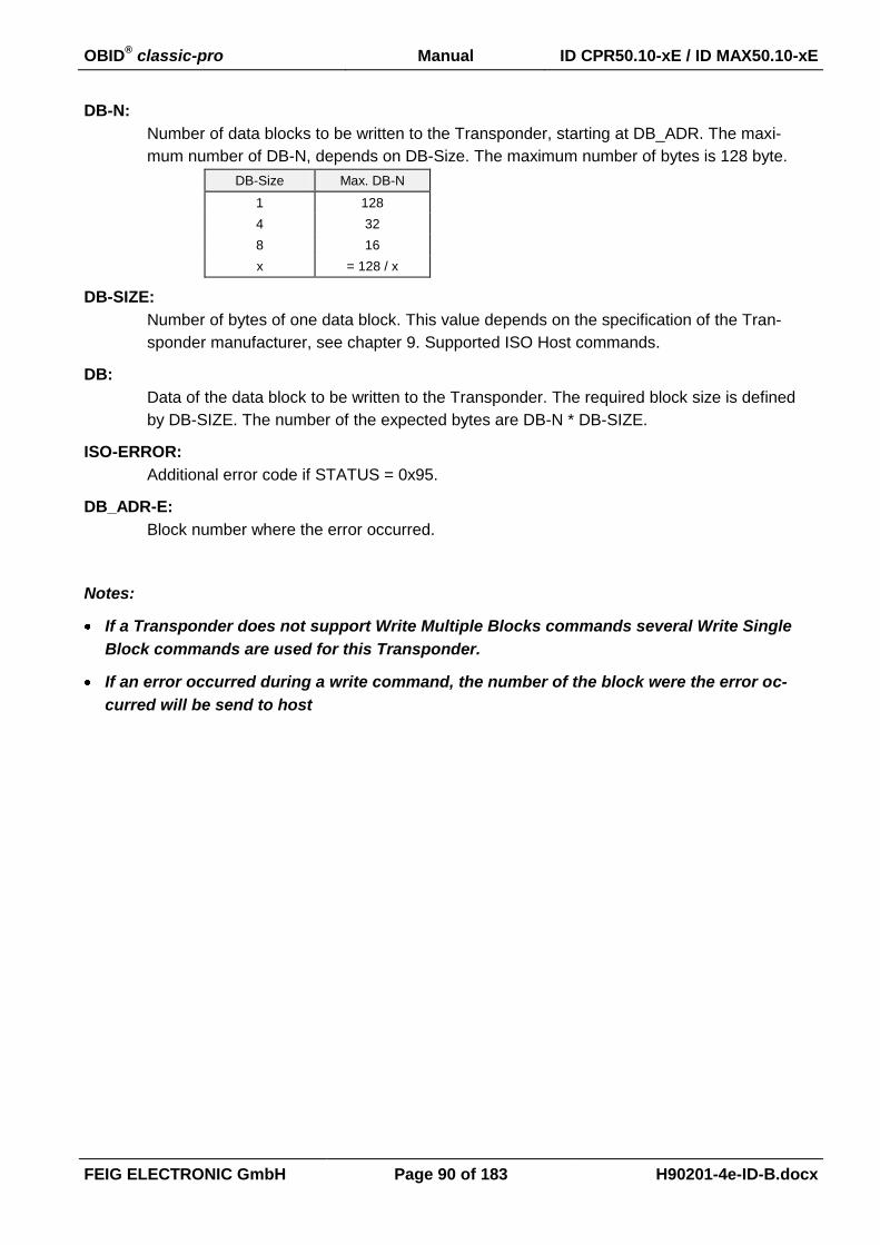
OBID® classic-pro Manual ID CPR50.10-xE / ID MAX50.10-xE
FEIG ELECTRONIC GmbH Page 90 of 183 H90201-4e-ID-B.docx
DB-N:
Number of data blocks to be written to the Transponder, starting at DB_ADR. The maxi-
mum number of DB-N, depends on DB-Size. The maximum number of bytes is 128 byte.
DB-Size Max. DB-N
1 128
4 32
8 16
x = 128 / x
DB-SIZE:
Number of bytes of one data block. This value depends on the specification of the Tran-
sponder manufacturer, see chapter 9. Supported ISO Host commands.
DB:
Data of the data block to be written to the Transponder. The required block size is defined
by DB-SIZE. The number of the expected bytes are DB-N * DB-SIZE.
ISO-ERROR:
Additional error code if STATUS = 0x95.
DB_ADR-E:
Block number where the error occurred.
Notes:
If a Transponder does not support Write Multiple Blocks commands several Write Single
Block commands are used for this Transponder.
If an error occurred during a write command, the number of the block were the error oc-
curred will be send to host
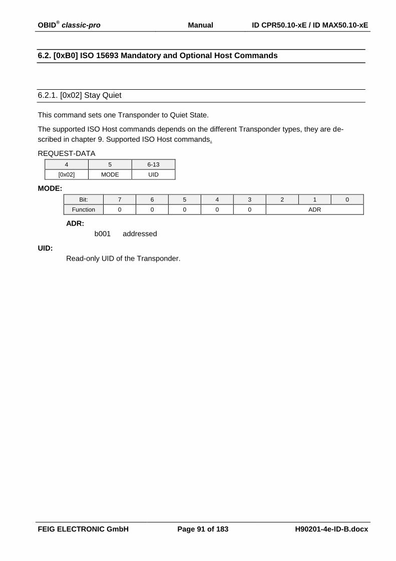
OBID® classic-pro Manual ID CPR50.10-xE / ID MAX50.10-xE
FEIG ELECTRONIC GmbH Page 91 of 183 H90201-4e-ID-B.docx
6.2. [0xB0] ISO 15693 Mandatory and Optional Host Commands
6.2.1. [0x02] Stay Quiet
This command sets one Transponder to Quiet State.
The supported ISO Host commands depends on the different Transponder types, they are de-
scribed in chapter 9. Supported ISO Host commands.
REQUEST-DATA
4 5 6-13
[0x02] MODE UID
MODE:
Bit: 7 6 5 4 3 2 1 0
Function 0 0 0 0 0 ADR
ADR:
b001 addressed
UID:
Read-only UID of the Transponder.
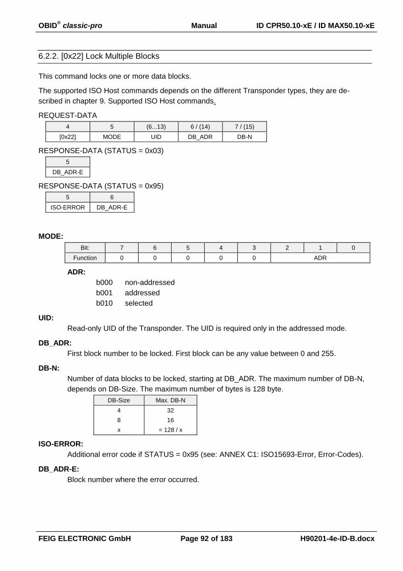
OBID® classic-pro Manual ID CPR50.10-xE / ID MAX50.10-xE
FEIG ELECTRONIC GmbH Page 92 of 183 H90201-4e-ID-B.docx
6.2.2. [0x22] Lock Multiple Blocks
This command locks one or more data blocks.
The supported ISO Host commands depends on the different Transponder types, they are de-
scribed in chapter 9. Supported ISO Host commands.
REQUEST-DATA
4 5 (6...13) 6 / (14) 7 / (15)
[0x22] MODE UID DB_ADR DB-N
RESPONSE-DATA (STATUS = 0x03)
5
DB_ADR-E
RESPONSE-DATA (STATUS = 0x95)
5 6
ISO-ERROR DB_ADR-E
MODE:
Bit: 7 6 5 4 3 2 1 0
Function 0 0 0 0 0 ADR
ADR:
b000 non-addressed
b001 addressed
b010 selected
UID:
Read-only UID of the Transponder. The UID is required only in the addressed mode.
DB_ADR:
First block number to be locked. First block can be any value between 0 and 255.
DB-N:
Number of data blocks to be locked, starting at DB_ADR. The maximum number of DB-N,
depends on DB-Size. The maximum number of bytes is 128 byte.
DB-Size Max. DB-N
4 32
8 16
x = 128 / x
ISO-ERROR:
Additional error code if STATUS = 0x95 (see: ANNEX C1: ISO15693-Error, Error-Codes).
DB_ADR-E:
Block number where the error occurred.
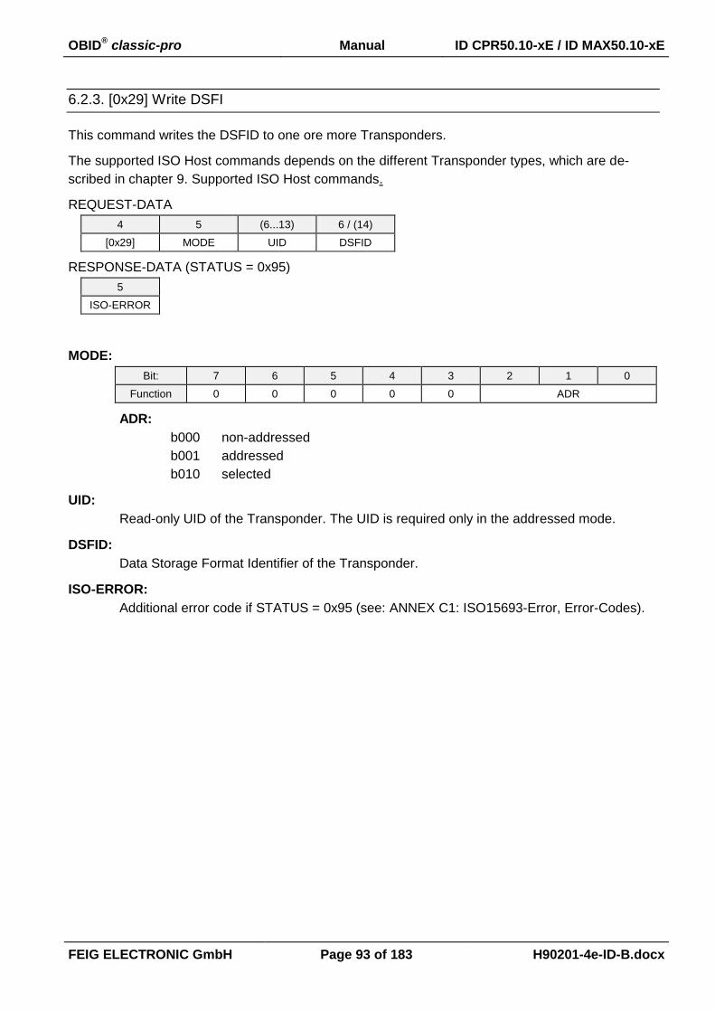
OBID® classic-pro Manual ID CPR50.10-xE / ID MAX50.10-xE
FEIG ELECTRONIC GmbH Page 93 of 183 H90201-4e-ID-B.docx
6.2.3. [0x29] Write DSFI
This command writes the DSFID to one ore more Transponders.
The supported ISO Host commands depends on the different Transponder types, which are de-
scribed in chapter 9. Supported ISO Host commands.
REQUEST-DATA
4 5 (6...13) 6 / (14)
[0x29] MODE UID DSFID
RESPONSE-DATA (STATUS = 0x95)
5
ISO-ERROR
MODE:
Bit: 7 6 5 4 3 2 1 0
Function 0 0 0 0 0 ADR
ADR:
b000 non-addressed
b001 addressed
b010 selected
UID:
Read-only UID of the Transponder. The UID is required only in the addressed mode.
DSFID:
Data Storage Format Identifier of the Transponder.
ISO-ERROR:
Additional error code if STATUS = 0x95 (see: ANNEX C1: ISO15693-Error, Error-Codes).

OBID® classic-pro Manual ID CPR50.10-xE / ID MAX50.10-xE
FEIG ELECTRONIC GmbH Page 94 of 183 H90201-4e-ID-B.docx
6.2.4. [0x26] Reset to Ready
This command sets one Transponder to Ready State.
The supported ISO Host commands depends on the different Transponder types, they are de-
scribed in chapter 9. Supported ISO Host commands.
REQUEST-DATA
4 5 (6...13)
[0x26] MODE UID
RESPONSE-DATA (STATUS = 0x95)
5
ISO-ERROR
MODE:
Bit: 7 6 5 4 3 2 1 0
Function 0 0 0 0 0 ADR
ADR:
b000 non-addressed
b001 addressed
b010 selected
UID:
Read-only UID of the Transponder. The UID is required only in the addressed mode.
ISO-ERROR:
Additional error code if STATUS = 0x95 (see: ANNEX C1: ISO15693-Error, Error-Codes).

OBID® classic-pro Manual ID CPR50.10-xE / ID MAX50.10-xE
FEIG ELECTRONIC GmbH Page 95 of 183 H90201-4e-ID-B.docx
6.2.5. [0x27] Write AFI
This command writes a new AFI code to one or more Transponders.
The supported ISO Host commands depends on the different Transponder Types, which are de-
scribed in chapter 9. Supported ISO Host commands.
REQUEST-DATA
4 5 (6...13) 6 / (14)
[0x27] MODE UID AFI
RESPONSE-DATA (STATUS = 0x95)
5
ISO-ERROR
MODE:
Bit: 7 6 5 4 3 2 1 0
Function 0 0 0 0 0 ADR
ADR:
b000 non-addressed
b001 addressed
b010 selected
UID:
Read-only UID of the Transponder. The UID is required only in the addressed mode.
AFI:
Application Family Identifier of the Transponder.
ISO-ERROR:
Additional error code if STATUS = 0x95 (see: ANNEX C1: ISO15693-Error, Error-Codes).
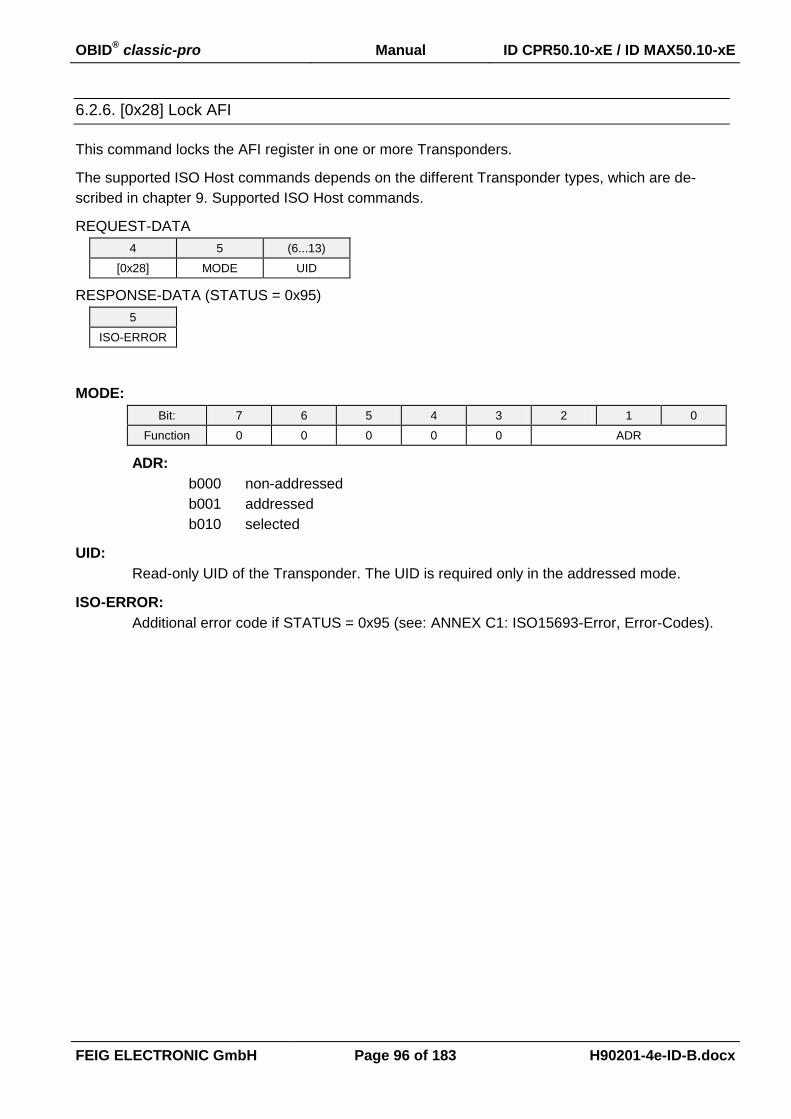
OBID® classic-pro Manual ID CPR50.10-xE / ID MAX50.10-xE
FEIG ELECTRONIC GmbH Page 96 of 183 H90201-4e-ID-B.docx
6.2.6. [0x28] Lock AFI
This command locks the AFI register in one or more Transponders.
The supported ISO Host commands depends on the different Transponder types, which are de-
scribed in chapter 9. Supported ISO Host commands.
REQUEST-DATA
4 5 (6...13)
[0x28] MODE UID
RESPONSE-DATA (STATUS = 0x95)
5
ISO-ERROR
MODE:
Bit: 7 6 5 4 3 2 1 0
Function 0 0 0 0 0 ADR
ADR:
b000 non-addressed
b001 addressed
b010 selected
UID:
Read-only UID of the Transponder. The UID is required only in the addressed mode.
ISO-ERROR:
Additional error code if STATUS = 0x95 (see: ANNEX C1: ISO15693-Error, Error-Codes).

OBID® classic-pro Manual ID CPR50.10-xE / ID MAX50.10-xE
FEIG ELECTRONIC GmbH Page 97 of 183 H90201-4e-ID-B.docx
6.2.7. [0x2A] Lock DSFI
This command locks the DSFID register in one or more Transponders.
The supported ISO Host commands depends on the different Transponder types, which are de-
scribed in chapter 9. Supported ISO Host commands.
REQUEST-DATA
4 5 (6...13)
[0x2A] MODE UID
RESPONSE-DATA (STATUS = 0x95)
5
ISO-ERROR
MODE:
Bit: 7 6 5 4 3 2 1 0
Function 0 0 0 0 0 ADR
ADR:
b000 non-addressed
b001 addressed
b010 selected
UID:
Read-only UID of the Transponder. The UID is required only in the addressed mode.
ISO-ERROR:
Additional error code if STATUS = 0x95 (see: ANNEX C1: ISO15693-Error, Error-Codes).
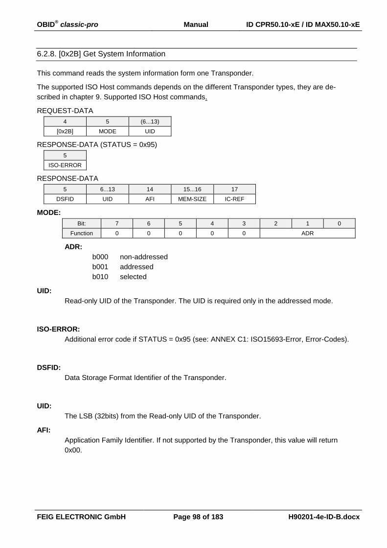
OBID® classic-pro Manual ID CPR50.10-xE / ID MAX50.10-xE
FEIG ELECTRONIC GmbH Page 98 of 183 H90201-4e-ID-B.docx
6.2.8. [0x2B] Get System Information
This command reads the system information form one Transponder.
The supported ISO Host commands depends on the different Transponder types, they are de-
scribed in chapter 9. Supported ISO Host commands.
REQUEST-DATA
4 5 (6...13)
[0x2B] MODE UID
RESPONSE-DATA (STATUS = 0x95)
5
ISO-ERROR
RESPONSE-DATA
5 6...13 14 15...16 17
DSFID UID AFI MEM-SIZE IC-REF
MODE:
Bit: 7 6 5 4 3 2 1 0
Function 0 0 0 0 0 ADR
ADR:
b000 non-addressed
b001 addressed
b010 selected
UID:
Read-only UID of the Transponder. The UID is required only in the addressed mode.
ISO-ERROR:
Additional error code if STATUS = 0x95 (see: ANNEX C1: ISO15693-Error, Error-Codes).
DSFID:
Data Storage Format Identifier of the Transponder.
UID:
The LSB (32bits) from the Read-only UID of the Transponder.
AFI:
Application Family Identifier. If not supported by the Transponder, this value will return
0x00.
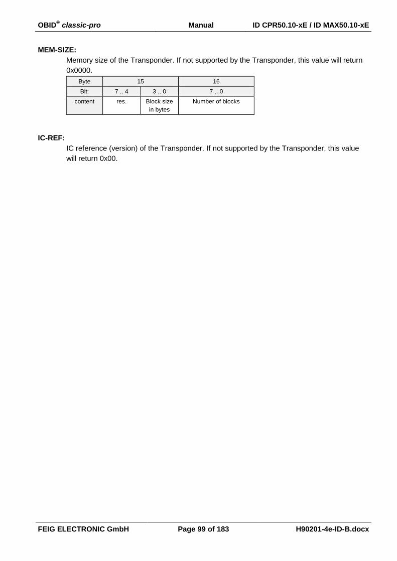
OBID® classic-pro Manual ID CPR50.10-xE / ID MAX50.10-xE
FEIG ELECTRONIC GmbH Page 99 of 183 H90201-4e-ID-B.docx
MEM-SIZE:
Memory size of the Transponder. If not supported by the Transponder, this value will return
0x0000.
Byte 15 16
Bit: 7 .. 4 3 .. 0 7 .. 0
content res. Block size
in bytes
Number of blocks
IC-REF:
IC reference (version) of the Transponder. If not supported by the Transponder, this value
will return 0x00.
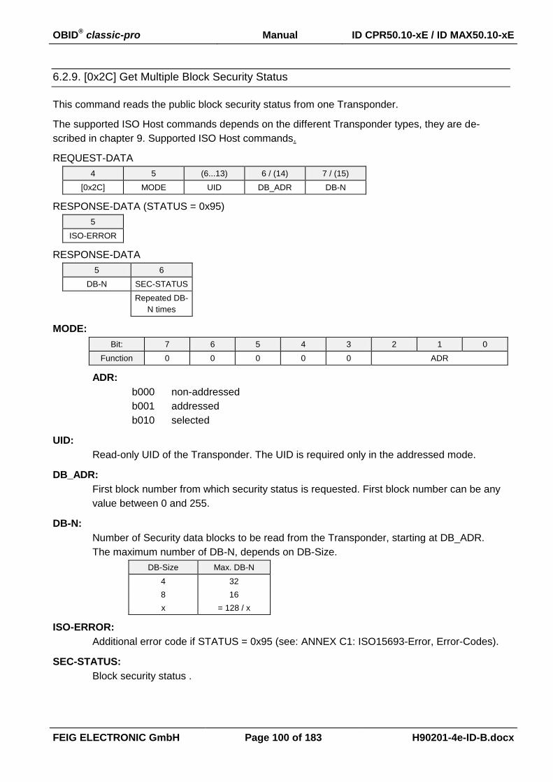
OBID® classic-pro Manual ID CPR50.10-xE / ID MAX50.10-xE
FEIG ELECTRONIC GmbH Page 100 of 183 H90201-4e-ID-B.docx
6.2.9. [0x2C] Get Multiple Block Security Status
This command reads the public block security status from one Transponder.
The supported ISO Host commands depends on the different Transponder types, they are de-
scribed in chapter 9. Supported ISO Host commands.
REQUEST-DATA
4 5 (6...13) 6 / (14) 7 / (15)
[0x2C] MODE UID DB_ADR DB-N
RESPONSE-DATA (STATUS = 0x95)
5
ISO-ERROR
RESPONSE-DATA
5 6
DB-N SEC-STATUS
Repeated DB-
N times
MODE:
Bit: 7 6 5 4 3 2 1 0
Function 0 0 0 0 0 ADR
ADR:
b000 non-addressed
b001 addressed
b010 selected
UID:
Read-only UID of the Transponder. The UID is required only in the addressed mode.
DB_ADR:
First block number from which security status is requested. First block number can be any
value between 0 and 255.
DB-N:
Number of Security data blocks to be read from the Transponder, starting at DB_ADR.
The maximum number of DB-N, depends on DB-Size.
DB-Size Max. DB-N
4 32
8 16
x = 128 / x
ISO-ERROR:
Additional error code if STATUS = 0x95 (see: ANNEX C1: ISO15693-Error, Error-Codes).
SEC-STATUS:
Block security status .

OBID® classic-pro Manual ID CPR50.10-xE / ID MAX50.10-xE
FEIG ELECTRONIC GmbH Page 101 of 183 H90201-4e-ID-B.docx
6.3. [0xB0] ISO 14443 Standard Host Commands
6.3.1. [0xC0] Halt
This command sets one ISO14443-3 Transponder into Halt State.
The supported ISO Host commands depends on the different Transponder types, they are de-
scribed in chapter 9. Supported ISO Host commands.
REQUEST-DATA
4 5
[0xC0] MODE
MODE:
Bit: 7 6 5 4 3 2 1 0
Function - - - - - ADR
ADR:
b010 selected
NOTICE:
If anticollision is enabled the Reader sets the Transponder into the Halt status itself.

OBID® classic-pro Manual ID CPR50.10-xE / ID MAX50.10-xE
FEIG ELECTRONIC GmbH Page 102 of 183 H90201-4e-ID-B.docx
6.4. [0xB2] ISO14443 Special Host Commands
The [0xB2] commands are supposed to send special ISO14443 defined commands and proprietary
ISO14443 RF commands to the Transponder.
Host Reader
1 2 3 4...n-2 n-1,n
n COM-ADR [0xB2] REQUEST-
DATA
CRC16
Host Reader
1 2 3 4 5...n-2 n-1,n
n COM-ADR [0xB2] STATUS RESPONSE-
DATA
CRC16
REQUEST-DATA:
Command specific request
RESPONSE-DATA:
Command specific response
Notes:
This command isn’t available if the notification/max mode is switched on.

OBID® classic-pro Manual ID CPR50.10-xE / ID MAX50.10-xE
FEIG ELECTRONIC GmbH Page 103 of 183 H90201-4e-ID-B.docx
6.4.1. [0x30] Mifare Value Commands
This command provides the Mifare value functions INCREMENT, DECREMENT, TRANSFER and
RESTORE of an value formatted Mifare sector block. The command returns an error if the block is
not in value block format (details about the Mifare value block format are described in Mifare stand-
ard data sheet provided by NXP). The command loads the value from a source address (DB_ADR),
operates the value function and stores the result at the destination address (DESTIN_ADR).
NOTICE:
A previous authentication (see: 6.4.2. [0xB0] Authent Mifare) is needed to process the
command.
The Mifare value block format could be written with the reader command 6.1.4. [0x24] Wri-
te Multiple Blocks.
REQUEST-DATA
4 5 6 7 8...11 12
[0x30] MODE MF_CMD DB_ADR OP_VALUE DEST_ADR
MSB ... LSB
MODE:
Bit: 7 6 5 4 3 2 1 0
Function 0 0 0 0 0 ADR
ADR:
b010 selected
MF_CMD:
This parameter defines the value operation which should be done on the Mifare Tran-
sponder.
0x01 INCREMENT
Adds the value OP_VALUE to the value specified by address DB_ADR.
0x02 DECREMENT
Subtracts the value OP_VALUE from the value specified by address DB_ADR.
0x03 COPY
Transfers the value structure from address DB_ADR to address DESTIN_ADR
without changing the value.
DB_ADR:
Source Mifare block address of the value formatted data. A formula to calculate DB_ADR
could be found in Chapter 9.2.2. NXP - Mifare classic: mini, 1k, 4k / mifare plus (Level 1)
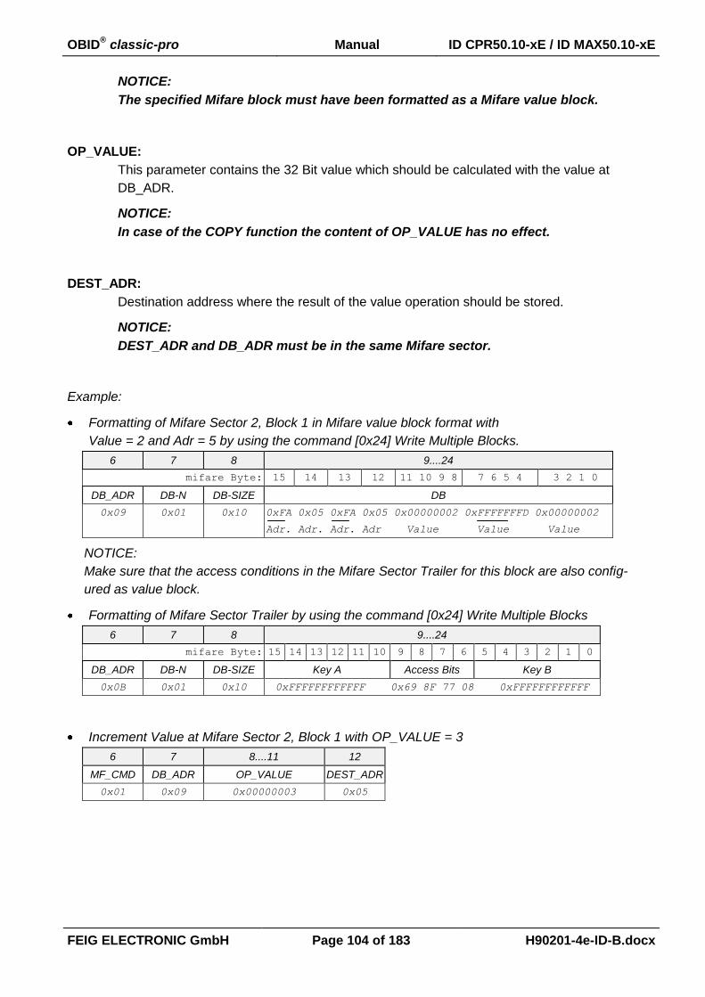
OBID® classic-pro Manual ID CPR50.10-xE / ID MAX50.10-xE
FEIG ELECTRONIC GmbH Page 104 of 183 H90201-4e-ID-B.docx
NOTICE:
The specified Mifare block must have been formatted as a Mifare value block.
OP_VALUE:
This parameter contains the 32 Bit value which should be calculated with the value at
DB_ADR.
NOTICE:
In case of the COPY function the content of OP_VALUE has no effect.
DEST_ADR:
Destination address where the result of the value operation should be stored.
NOTICE:
DEST_ADR and DB_ADR must be in the same Mifare sector.
Example:
Formatting of Mifare Sector 2, Block 1 in Mifare value block format with
Value = 2 and Adr = 5 by using the command [0x24] Write Multiple Blocks.
6 7 8 9....24
mifare Byte: 15 14 13 12 11 10 9 8 7 6 5 4 3 2 1 0
DB_ADR DB-N DB-SIZE DB
0x09 0x01 0x10 0xFA 0x05 0xFA 0x05 0x00000002 0xFFFFFFFD 0x00000002
Adr. Adr. Adr. Adr Value Value Value
NOTICE:
Make sure that the access conditions in the Mifare Sector Trailer for this block are also config-
ured as value block.
Formatting of Mifare Sector Trailer by using the command [0x24] Write Multiple Blocks
6 7 8 9....24
mifare Byte: 15 14 13 12 11 10 9 8 7 6 5 4 3 2 1 0
DB_ADR DB-N DB-SIZE Key A Access Bits Key B
0x0B 0x01 0x10 0xFFFFFFFFFFFF 0x69 8F 77 08 0xFFFFFFFFFFFF
Increment Value at Mifare Sector 2, Block 1 with OP_VALUE = 3
6 7 8....11 12
MF_CMD DB_ADR OP_VALUE DEST_ADR
0x01 0x09 0x00000003 0x05
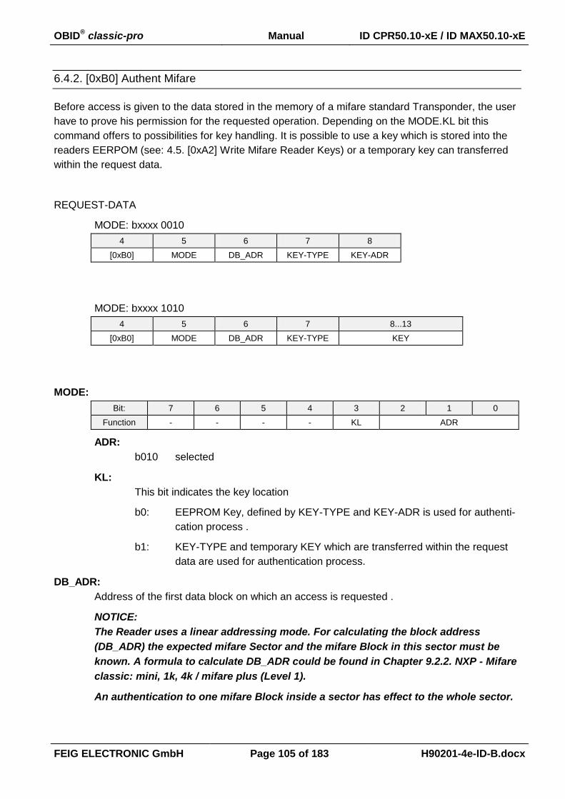
OBID® classic-pro Manual ID CPR50.10-xE / ID MAX50.10-xE
FEIG ELECTRONIC GmbH Page 105 of 183 H90201-4e-ID-B.docx
6.4.2. [0xB0] Authent Mifare
Before access is given to the data stored in the memory of a mifare standard Transponder, the user
have to prove his permission for the requested operation. Depending on the MODE.KL bit this
command offers to possibilities for key handling. It is possible to use a key which is stored into the
readers EERPOM (see: 4.5. [0xA2] Write Mifare Reader Keys) or a temporary key can transferred
within the request data.
REQUEST-DATA
MODE: bxxxx 0010
4 5 6 7 8
[0xB0] MODE DB_ADR KEY-TYPE KEY-ADR
MODE: bxxxx 1010
4 5 6 7 8...13
[0xB0] MODE DB_ADR KEY-TYPE KEY
MODE:
Bit: 7 6 5 4 3 2 1 0
Function - - - - KL ADR
ADR:
b010 selected
KL:
This bit indicates the key location
b0: EEPROM Key, defined by KEY-TYPE and KEY-ADR is used for authenti-
cation process .
b1: KEY-TYPE and temporary KEY which are transferred within the request
data are used for authentication process.
DB_ADR:
Address of the first data block on which an access is requested .
NOTICE:
The Reader uses a linear addressing mode. For calculating the block address
(DB_ADR) the expected mifare Sector and the mifare Block in this sector must be
known. A formula to calculate DB_ADR could be found in Chapter 9.2.2. NXP - Mifare
classic: mini, 1k, 4k / mifare plus (Level 1).
An authentication to one mifare Block inside a sector has effect to the whole sector.

OBID® classic-pro Manual ID CPR50.10-xE / ID MAX50.10-xE
FEIG ELECTRONIC GmbH Page 106 of 183 H90201-4e-ID-B.docx
KEY-TYPE:
Defines the key for the authentication.
0x00: KEY A
0x01 KEY B
KEY-ADR:
EEPROM Address (0x00 ... 0x0F) where the key is stored in the Reader (see: 4.5. [0xA2]
Write Mifare Reader Keys).
KEY:
6 byte Mifare Key which should used for the current authentication process.

OBID® classic-pro Manual ID CPR50.10-xE / ID MAX50.10-xE
FEIG ELECTRONIC GmbH Page 107 of 183 H90201-4e-ID-B.docx
6.4.3. [0xB2] Authent Mifare Ultralight C
Before access is given to the data stored in the memory of a mifare ultralight C transponder, the
user have to prove his permission for the requested operation. The key for authentication used by
the reader can be stored into the readers EEPROM or RAM (see: 4.6. [0xA3] Write DES/AES
Reader Keys).
REQUEST-DATA
4 5 6
[0xB2] MODE READER-
KEY-NDX
MODE:
Bit: 7 6 5 4 3 2 1 0
Function - - - - - ADR
ADR:
b010 selected
READER-KEY-NDX (0...3)
Index of the key which is stored in the reader (see: 4.6. [0xA3] Write DES/AES Reader
Keys) and which shall be used for authentication for the current command.
NOTICE:
Only keys with AUTH-MODE = 1 can be used for mifare ultralight C.

OBID® classic-pro Manual ID CPR50.10-xE / ID MAX50.10-xE
FEIG ELECTRONIC GmbH Page 108 of 183 H90201-4e-ID-B.docx
6.4.4. [0xBE] ISO 14443-4 T=CL (#)
This command provides the data exchange between a host and the Transponder on ISO 14443-4
layer. It is special designed for easy APDU data exchange.
NOTICE:
The maximum buffer size of the Reader for data exchange has to be considered and can
be determined with command [0x66], Mode = 0x00.
REQUEST-DATA
4 5 (6...n-2)
[0xBE] MODE (DATA)
RESPONSE-DATA
4 (5) (6...7) (8...n-2)
STATUS (PSTAT) (BLK_CNT) (DATA)

OBID® classic-pro Manual ID CPR50.10-xE / ID MAX50.10-xE
FEIG ELECTRONIC GmbH Page 109 of 183 H90201-4e-ID-B.docx
MODE:
Bit: 7 6 5 4 3 2 1 0
Function FIRST MORE - - PING NAD_E CID_E INF
MODE bit setting rules
MODE DATA
6 7 8...n-2
b1000 0001 (INF) APDU without CID or NAD (single block)
b1100 0001 (INF) APDU without CID or NAD (first chained block)
b0100 0001 (INF) APDU without CID or NAD (further chained block)
b0000 0001 (INF) APDU without CID or NAD (last chained block)
b1000 0011 CID (INF) APDU with CID (single block)
b1100 0011 CID (INF) APDU with CID (first chained block)
b1000 0101 NAD (INF) APDU with NAD (single block)
b1100 0101 NAD (INF) APDU with NAD (first chained block)
b1000 0111 CID NAD (INF) APDU with CID and NAD (single block)
b1100 0111 CID NAD (INF) APDU with CID and NAD (first chained block)
b1000 0000 - DESLECT without CID or NAD
b1000 0010 CID - DESLECT with CID
b1000 100x - PING without CID or NAD
b1000 101x CID - PING with CID
INF:
b0 "DESELECT"
Sends the S-block command "DESELECT" to the present Transponder.
b1 "APDU"
Instructs the Reader to send the INF Block (APDU) which is included in
the DATA Block to the Transponder.
CID_E:
b0 The DATA Block includes no CID
b1: The DATA Block includes an optional 1 byte CID Parameter
The CID has to be placed in DATA directly behind the MODE Parameter
NOTICE:
In case of command chaining (see Bit "MORE") only the CID in the first
command block is accepted by the Reader.
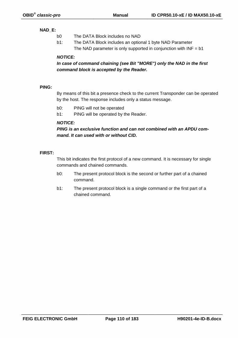
OBID® classic-pro Manual ID CPR50.10-xE / ID MAX50.10-xE
FEIG ELECTRONIC GmbH Page 110 of 183 H90201-4e-ID-B.docx
NAD_E:
b0 The DATA Block includes no NAD
b1: The DATA Block includes an optional 1 byte NAD Parameter
The NAD parameter is only supported in conjunction with INF = b1
NOTICE:
In case of command chaining (see Bit "MORE") only the NAD in the first
command block is accepted by the Reader.
PING:
By means of this bit a presence check to the current Transponder can be operated
by the host. The response includes only a status message.
b0: PING will not be operated
b1: PING will be operated by the Reader.
NOTICE:
PING is an exclusive function and can not combined with an APDU com-
mand. It can used with or without CID.
FIRST:
This bit indicates the first protocol of a new command. It is necessary for single
commands and chained commands.
b0: The present protocol block is the second or further part of a chained
command.
b1: The present protocol block is a single command or the first part of a
chained command.

OBID® classic-pro Manual ID CPR50.10-xE / ID MAX50.10-xE
FEIG ELECTRONIC GmbH Page 111 of 183 H90201-4e-ID-B.docx
MORE:
By means of this bit a data chaining from the host to the Reader could realized if
the number of data bytes which should be send beyond the receive buffer size of
the Reader.
b0 No downlink chaining (Host Reader)
The present protocol block includes the complete command.
b1 downlink chaining (Host Reader)
The present protocol block includes not the complete command.
After the reader has acknowledged the protocol block the host can send
further parts of the command.
NOTICE:
If an error status is responded by the Reader the downlink chaining
should stopped by the host.
If a MORE status (0x94) is responded by the Reader the host has to han-
dle this message.
Protocol examples for Error-free operation with 3 blocks and 1 MORE response
DATA
MODE:
b11xx 0xx1
(CID), (NAD), INF Host Reader (1. protocol block)
STATUS: 0x94
(MORE)
Host Reader
STATUS: 0x00
(OK)
Host Reader
b01xx 0001 INF Host Reader (2. protocol block)
STATUS:
0x00 (OK)
Host Reader
b00xx 0001 INF Host Reader (last protocol block)
STATUS:
0x00 (OK)
Host Reader
DATA:
The DATA Field could be used to transfer the optional CID, NAD and INF Field of the
ISO14443-4 communication protocol.
In most cases the INF Field carries an APDU to the Transponder.
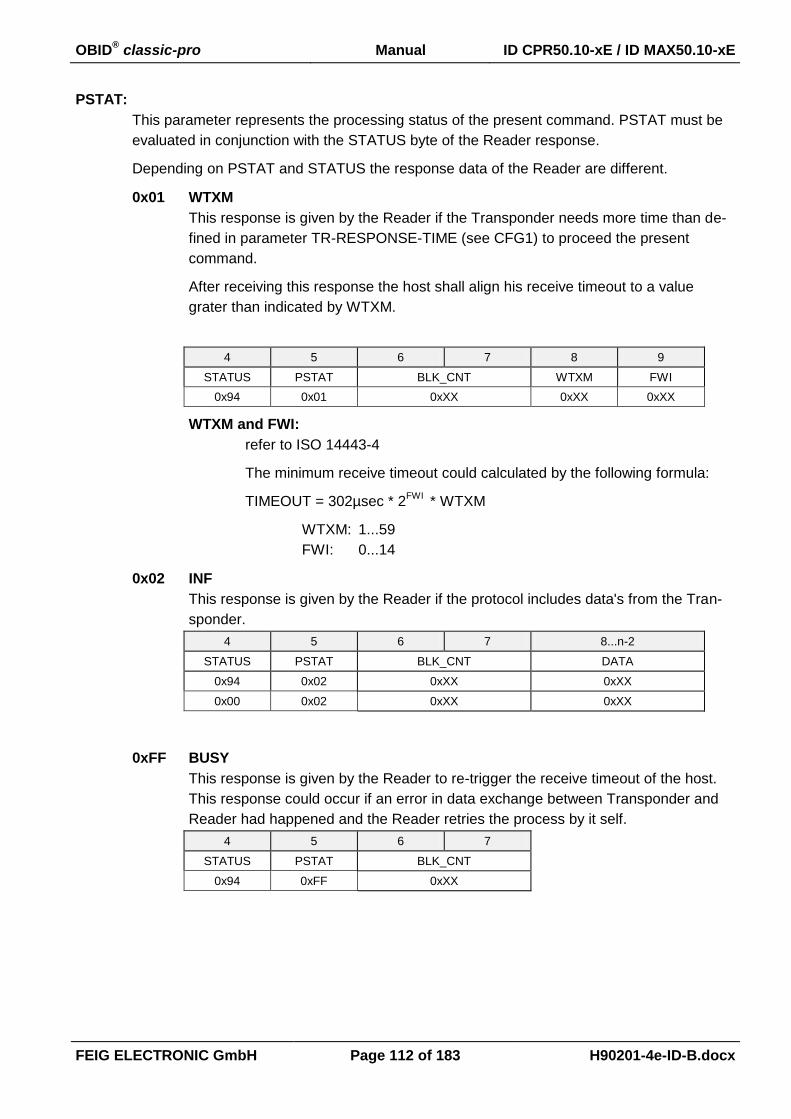
OBID® classic-pro Manual ID CPR50.10-xE / ID MAX50.10-xE
FEIG ELECTRONIC GmbH Page 112 of 183 H90201-4e-ID-B.docx
PSTAT:
This parameter represents the processing status of the present command. PSTAT must be
evaluated in conjunction with the STATUS byte of the Reader response.
Depending on PSTAT and STATUS the response data of the Reader are different.
0x01 WTXM
This response is given by the Reader if the Transponder needs more time than de-
fined in parameter TR-RESPONSE-TIME (see CFG1) to proceed the present
command.
After receiving this response the host shall align his receive timeout to a value
grater than indicated by WTXM.
4 5 6 7 8 9
STATUS PSTAT BLK_CNT WTXM FWI
0x94 0x01 0xXX 0xXX 0xXX
WTXM and FWI:
refer to ISO 14443-4
The minimum receive timeout could calculated by the following formula:
TIMEOUT = 302µsec * 2FWI
* WTXM
WTXM: 1...59
FWI: 0...14
0x02 INF
This response is given by the Reader if the protocol includes data's from the Tran-
sponder.
4 5 6 7 8...n-2
STATUS PSTAT BLK_CNT DATA
0x94 0x02 0xXX 0xXX
0x00 0x02 0xXX 0xXX
0xFF BUSY
This response is given by the Reader to re-trigger the receive timeout of the host.
This response could occur if an error in data exchange between Transponder and
Reader had happened and the Reader retries the process by it self.
4 5 6 7
STATUS PSTAT BLK_CNT
0x94 0xFF 0xXX

OBID® classic-pro Manual ID CPR50.10-xE / ID MAX50.10-xE
FEIG ELECTRONIC GmbH Page 113 of 183 H90201-4e-ID-B.docx
STATUS = ERROR (STATUS not 0x00 or 0x94)
This response is given by the Reader if the present command could not be fin-
ished, because of transmission errors.
4 5
STATUS (ISO14443-
ERROR)
STATUS:
see ANNEX C: Index of Status Bytes.
ISO14443-ERROR
Additional error code if STATUS = 0x96 (see ANNEX C2: ISO14443-
Error, Error-Codes)
BLK_CNT:
The BLK_CNT is a block counter which indexes each transmission from the Reader to the
Host. On basis of the BLK_CNT the host could proof and sort the received protocols.

OBID® classic-pro Manual ID CPR50.10-xE / ID MAX50.10-xE
FEIG ELECTRONIC GmbH Page 114 of 183 H90201-4e-ID-B.docx
6.4.5. [0xBF] ISO 14443-4 Container Command (#)
This command encapsulates and transports the ISO 14443-4 commands to the Transponder. The
Command enables the transparent data exchange between host and Transponder as described in
ISO 14443-4.
REQUEST-DATA
4 5 6 7...n-2
[0xBF] RSP TIMEOUT
(FWI)
REQUEST-
BLOCK
RESPONSE-DATA
#..n-2
RESPONSE-DATA
NOTICE:
The maximum buffer for the RESPOSE-DATA is 256 byte (FSDI = 8).
RSP:
0 The Reader will send the command to the Transponder but do not wait for any re-
sponse from the Transponder. Is option should only used if the command doesn’t
have any response.
> 0 The Reader will send the command and is waiting for a response form the Tran-
sponder while the time period defined in TIMEOUT is running or the Transponder
had send a response.

OBID® classic-pro Manual ID CPR50.10-xE / ID MAX50.10-xE
FEIG ELECTRONIC GmbH Page 115 of 183 H90201-4e-ID-B.docx
TIMEOUT (FWI):
With this parameter the Frame waiting time (FWT) according ISO14443-4 could be select
by the user
TIMEOUT
(FWI)
approx. Frame waiting time
(FWT)
0 1 ms
1 1 ms
2 2 ms
3 3 ms
4 5 ms
5 10 ms
6 20 ms
7 39 ms
8 78 ms
9 155 ms
10 310 ms
11 619 ms
12 1237 ms
13 2474 ms
14 4948 ms
15..254 - not allowed -
255 automatically
NOTICE:
If TIMEOUT = 255 is chosen the Reader used the FWI as transmitted from the
Transponder.
The value of TIMEOUT must be considered for calculating the TR-RESPONSE-
TIME (see CFG1)
REQUEST-BLOCK:
This Parameter with variable length is provided for the transparent data transfer to the
Transponder. Refer to ISO 14443-4, chapter "Block Format"
Prologue filed Information
field
Epilogue field
PCB [CID] [NAD] [INF] EDC
1 Byte 1 Byte 1 Byte x Byte 2 Byte
NOTICE:
PCB is mandatory for each command whereas the parameters in [ ] brackets are op-
tional. For further Information please see ISO/IEC ISO14443-4
The maximum size of a REQUEST-BLOCK is 64 byte.
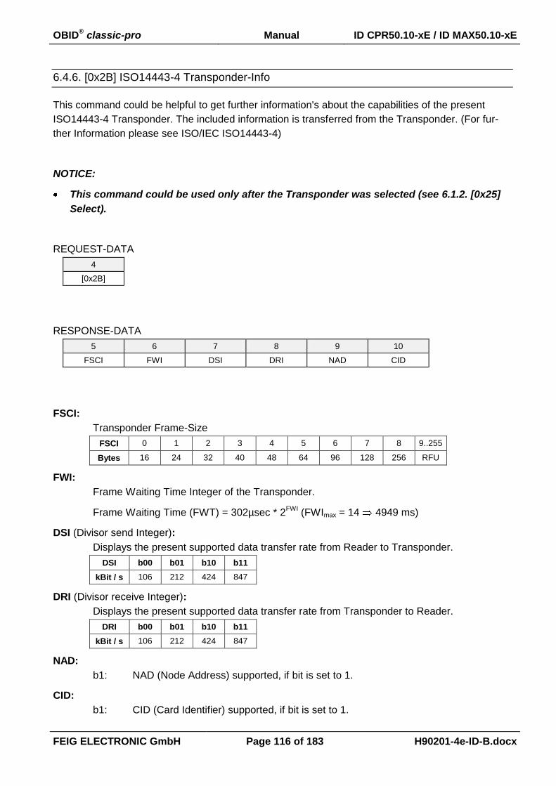
OBID® classic-pro Manual ID CPR50.10-xE / ID MAX50.10-xE
FEIG ELECTRONIC GmbH Page 116 of 183 H90201-4e-ID-B.docx
6.4.6. [0x2B] ISO14443-4 Transponder-Info
This command could be helpful to get further information's about the capabilities of the present
ISO14443-4 Transponder. The included information is transferred from the Transponder. (For fur-
ther Information please see ISO/IEC ISO14443-4)
NOTICE:
This command could be used only after the Transponder was selected (see 6.1.2. [0x25]
Select).
REQUEST-DATA
4
[0x2B]
RESPONSE-DATA
5 6 7 8 9 10
FSCI FWI DSI DRI NAD CID
FSCI:
Transponder Frame-Size
FSCI 0 1 2 3 4 5 6 7 8 9..255
Bytes 16 24 32 40 48 64 96 128 256 RFU
FWI:
Frame Waiting Time Integer of the Transponder.
Frame Waiting Time (FWT) = 302µsec * 2FWI
(FWImax = 14 4949 ms)
DSI (Divisor send Integer):
Displays the present supported data transfer rate from Reader to Transponder.
DSI b00 b01 b10 b11
kBit / s 106 212 424 847
DRI (Divisor receive Integer):
Displays the present supported data transfer rate from Transponder to Reader.
DRI b00 b01 b10 b11
kBit / s 106 212 424 847
NAD:
b1: NAD (Node Address) supported, if bit is set to 1.
CID:
b1: CID (Card Identifier) supported, if bit is set to 1.

OBID® classic-pro Manual ID CPR50.10-xE / ID MAX50.10-xE
FEIG ELECTRONIC GmbH Page 117 of 183 H90201-4e-ID-B.docx
6.5. [0xC1] / [0xC3] ISO Host Commands for mifare DESFire Communication
Mifare DESFire can be operated on APDU command level or with high level commands, implement-
ed in firmware.
Chapter 9.1.2. NXP - mifare DESFire gives an overview about the available commands for mifare
DESFire.
High level commands for mifare DESFire communication are described in separate manuals.
6.6. [0xC2] ISO Host Commands for mifare Plus Communication
Security Level 3
Mifare Plus in Security Level 3 can be operated on APDU command level or with high level
commands, implemented in firmware.
Chapter 9.1.3. NXP - mifare Plus (Security Level 3) gives an overview about the available
commands for this security levels.
Security Level 1
Mifare Plus in Security Level 1 can be operated with commands for mifare classic.
Chapter 9.2.2. NXP - Mifare classic: mini, 1k, 4k / mifare plus (Level 1) gives an overview
about the available commands for mifare Plus Security Level 1
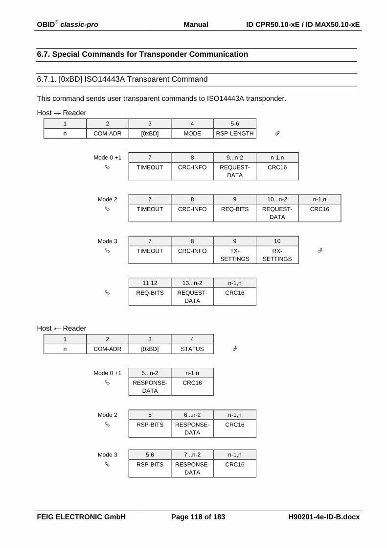
OBID® classic-pro Manual ID CPR50.10-xE / ID MAX50.10-xE
FEIG ELECTRONIC GmbH Page 118 of 183 H90201-4e-ID-B.docx
6.7. Special Commands for Transponder Communication
6.7.1. [0xBD] ISO14443A Transparent Command
This command sends user transparent commands to ISO14443A transponder.
Host Reader
1 2 3 4 5-6
n COM-ADR [0xBD] MODE RSP-LENGTH
Mode 0 +1 7 8 9...n-2 n-1,n
TIMEOUT CRC-INFO REQUEST-
DATA
CRC16
Mode 2 7 8 9 10...n-2 n-1,n
TIMEOUT CRC-INFO REQ-BITS REQUEST-
DATA
CRC16
Mode 3 7 8 9 10
TIMEOUT CRC-INFO TX-
SETTINGS
RX-
SETTINGS
11,12 13...n-2 n-1,n
REQ-BITS REQUEST-
DATA
CRC16
Host Reader
1 2 3 4
n COM-ADR [0xBD] STATUS
Mode 0 +1 5...n-2 n-1,n
RESPONSE-
DATA
CRC16
Mode 2 5 6...n-2 n-1,n
RSP-BITS RESPONSE-
DATA
CRC16
Mode 3 5,6 7...n-2 n-1,n
RSP-BITS RESPONSE-
DATA
CRC16

OBID® classic-pro Manual ID CPR50.10-xE / ID MAX50.10-xE
FEIG ELECTRONIC GmbH Page 119 of 183 H90201-4e-ID-B.docx
MODE:
Options for frame format request.
The following frame types are defined:
- short frames for commands like REQA, WUPA, ...
- standard frames for regular commands;
- bit oriented anticollision frame for anticollision command
- bit oriented frame with variable bitrates
0 = short frame
A short frame is used to initiate communication and consists of, in the following or-
der:
- start of communication.
- 7 data bits transmitted LSB first
- end of communication.
- No parity bit is added.
1 = standard frame
Standard frames are used for data exchange and consist of:
- start of communication.
- n * (8 data bits + odd parity bit), with n _ 1. The LSB of each byte is transmitted
first. Each byte is followed by an odd parity bit. The parity bit P is set such that the
number of 1s is odd in (b1 to b8, P).
- end of communication.
2 = bit oriented frame
Bit oriented Frames are used for anticollision.
3 = bit oriented frame with variable bitrates
Bit oriented frames with variable Tx- and Rx-Bitrates
RSP-LENGTH
If RSP-LENGTH is set to “0” the Reader will send the command but not wait for any re-
sponse. If RSP-LENGTH is not equal to “0” the Reader will send the command and return
the response data of the Transponder without SOF and EOF.
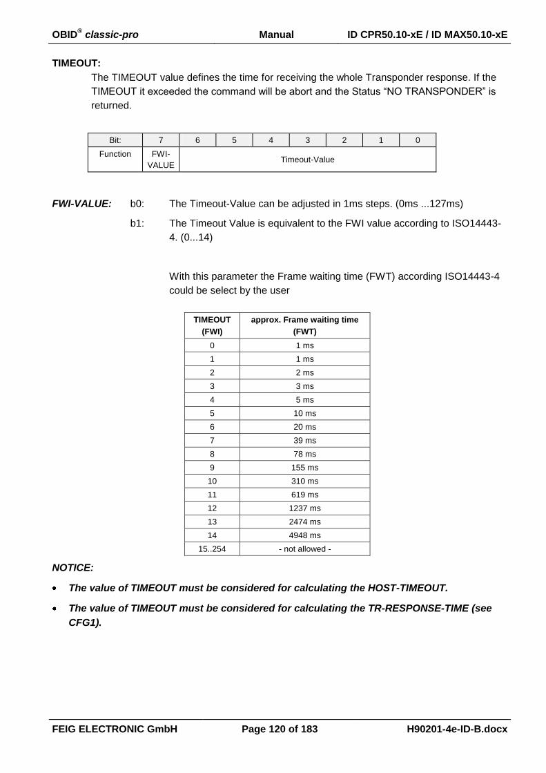
OBID® classic-pro Manual ID CPR50.10-xE / ID MAX50.10-xE
FEIG ELECTRONIC GmbH Page 120 of 183 H90201-4e-ID-B.docx
TIMEOUT:
The TIMEOUT value defines the time for receiving the whole Transponder response. If the
TIMEOUT it exceeded the command will be abort and the Status “NO TRANSPONDER” is
returned.
Bit: 7 6 5 4 3 2 1 0
Function FWI-
VALUE Timeout-Value
FWI-VALUE: b0: The Timeout-Value can be adjusted in 1ms steps. (0ms ...127ms)
b1: The Timeout Value is equivalent to the FWI value according to ISO14443-
4. (0...14)
With this parameter the Frame waiting time (FWT) according ISO14443-4
could be select by the user
TIMEOUT
(FWI)
approx. Frame waiting time
(FWT)
0 1 ms
1 1 ms
2 2 ms
3 3 ms
4 5 ms
5 10 ms
6 20 ms
7 39 ms
8 78 ms
9 155 ms
10 310 ms
11 619 ms
12 1237 ms
13 2474 ms
14 4948 ms
15..254 - not allowed -
NOTICE:
The value of TIMEOUT must be considered for calculating the HOST-TIMEOUT.
The value of TIMEOUT must be considered for calculating the TR-RESPONSE-TIME (see
CFG1).
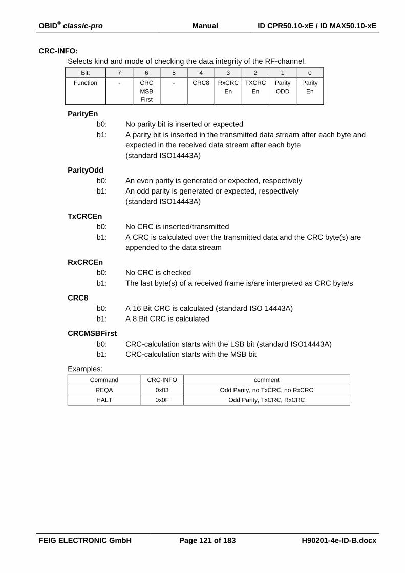
OBID® classic-pro Manual ID CPR50.10-xE / ID MAX50.10-xE
FEIG ELECTRONIC GmbH Page 121 of 183 H90201-4e-ID-B.docx
CRC-INFO:
Selects kind and mode of checking the data integrity of the RF-channel.
Bit: 7 6 5 4 3 2 1 0
Function - CRC
MSB
First
- CRC8 RxCRC
En
TXCRC
En
Parity
ODD
Parity
En
ParityEn
b0: No parity bit is inserted or expected
b1: A parity bit is inserted in the transmitted data stream after each byte and
expected in the received data stream after each byte
(standard ISO14443A)
ParityOdd
b0: An even parity is generated or expected, respectively
b1: An odd parity is generated or expected, respectively
(standard ISO14443A)
TxCRCEn
b0: No CRC is inserted/transmitted
b1: A CRC is calculated over the transmitted data and the CRC byte(s) are
appended to the data stream
RxCRCEn
b0: No CRC is checked
b1: The last byte(s) of a received frame is/are interpreted as CRC byte/s
CRC8
b0: A 16 Bit CRC is calculated (standard ISO 14443A)
b1: A 8 Bit CRC is calculated
CRCMSBFirst
b0: CRC-calculation starts with the LSB bit (standard ISO14443A)
b1: CRC-calculation starts with the MSB bit
Examples:
Command CRC-INFO comment
REQA 0x03 Odd Parity, no TxCRC, no RxCRC
HALT 0x0F Odd Parity, TxCRC, RxCRC

OBID® classic-pro Manual ID CPR50.10-xE / ID MAX50.10-xE
FEIG ELECTRONIC GmbH Page 122 of 183 H90201-4e-ID-B.docx
TX-SETTINGS:
Selects kind and mode of transmission settings.
Bit: 7 6 5 4 3 2 1 0
Function - - - - - - BAUDRATE
BAUDRATE
b00: 106 kBaud
b01: 212 kBaud
b10: 424 kBaud
b11: 848 kBaud
RX-SETTINGS:
Selects kind and mode of reception settings.
Bit: 7 6 5 4 3 2 1 0
Function - - - - - - BAUDRATE
BAUDRATE
b00: 106 kBaud
b01: 212 kBaud
b10: 424 kBaud
b11: 848 kBaud
REQ-BITS:
Number of valid Bits in REQUEST-DATA
REQUEST-DATA:
Complete transponder request without SOF and EOF. If “TxCRCEn” is “1” the reader ap-
pended a calculated CRC to the date stream. If “TxCRCEn” is “0” the application should
send the CRC within the Request-Data, if the CRC is needed.
RESPONSE-DATA:
Complete transponder response without SOF and EOF. A CRC check is performed inside
the reader if “RxCRCEn” is “1”. However if “RxCRCEn” is “0”the transponder CRC is
transferred with the response data.
RSP-BITS:
Number of valid Bits in RESPONSE-DATA
NOTICE:
Data is only transferred if STATUS = 0x00, 0x02, 0x83, 0x84, 0x94.

OBID® classic-pro Manual ID CPR50.10-xE / ID MAX50.10-xE
FEIG ELECTRONIC GmbH Page 123 of 183 H90201-4e-ID-B.docx
6.7.2. [0xBE] ISO14443B Transparent Command
This command sends user transparent commands to ISO14443B transponder.
Host Reader
1 2 3 4 5-6
n COM-ADR [0xBE] MODE RSP-LENGTH
Mode 0 7 8 9 10...n-2 n-1,n
TIMEOUT FRAME CRC-INFO REQUEST-
DATA
CRC16
Mode 1 7 8 9 10
TIMEOUT FRAME CRC-INFO TX-
SETTINGS
11 12,13 14...n-2 n-1,n
RX-
SETTINGS
REQ-BITS REQUEST-
DATA
CRC16
Host Reader
1 2 3 4 5...n-2 n-1,n
n COM-ADR [0xBE] STATUS RESPONSE-
DATA
CRC16
MODE:
Options for frame format request.
The following frame types are defined:
- standard frames for regular commands;
- bit oriented frame
0 = standard frame
Standard frames are used for data exchange and consist of:
- start of communication
- n * (8 data bits). The LSB of each byte is transmitted first.
- end of communication
1 = bit oriented frame with variable bitrates
Bit oriented frames with variable Tx- and Rx-Bitrates

OBID® classic-pro Manual ID CPR50.10-xE / ID MAX50.10-xE
FEIG ELECTRONIC GmbH Page 124 of 183 H90201-4e-ID-B.docx
RSP-LENGTH:
If RSP-LENGTH is set to “0” the Reader will send the command but not wait for any re-
sponse. If RSP-LENGTH is not equal to “0” the Reader will send the command and return
the response data of the Transponder without SOF and EOF.
TIMEOUT:
The TIMEOUT value defines the time for receiving the whole Transponder response. If the
TIMEOUT it exceeded the command will be abort and the Status “NO TRANSPONDER” is
returned.
Bit: 7 6 5 4 3 2 1 0
Function FWI-
VALUE Timeout-Value
FWI-VALUE: b0: The Timeout-Value can be adjusted in 1ms steps. (0ms ...127ms)
b1: The Timeout Value is equivalent to the FWI value according to
ISO14443-4. (0...14)
With this parameter the Frame waiting time (FWT) according ISO14443-4
could be select by the user
TIMEOUT
(FWI)
approx. Frame waiting time
(FWT)
0 1 ms
1 1 ms
2 2 ms
3 3 ms
4 5 ms
5 10 ms
6 20 ms
7 39 ms
8 78 ms
9 155 ms
10 310 ms
11 619 ms
12 1237 ms
13 2474 ms
14 4948 ms
15..254 - not allowed -
NOTICE:
The value of TIMEOUT must be considered for calculating the HOST-TIMEOUT.
The value of TIMEOUT must be considered for calculating the TR-RESPONSE-TIME (see
CFG1).

OBID® classic-pro Manual ID CPR50.10-xE / ID MAX50.10-xE
FEIG ELECTRONIC GmbH Page 125 of 183 H90201-4e-ID-B.docx
FRAME:
Defines the framing for ISO 14443B transponders.
Bit: 7 6 5 4 3 2 1 0
Function NO
TxSOF
No
TxEOF
EOF
Width
CharSpacing
SOF Width
SOFWidth
b00: Set the SOF to a length of 10 ETU Low and 2 ETU High
b01: Set the SOF to a length of 10 ETU Low and 3 ETU High
b10: Set the SOF to a length of 11 ETU Low and 2 ETU High
b11: Set the SOF to a length of 11 ETU Low and 3 ETU High
CharSpacing
Set the length of the EGT between 0 and 7 ETU.
EOFWidth
b0: Set the EOF to a length of 10 ETU
b1: Set the EOF to a length of 11 ETU
NoTxEOF
b0: The frame includes EOF
b1: TxCoder suppresses the EOF
NoTxSOF
b0: The frame includes SOF
b1: TxCoder suppresses the SOF
Examples:
Command FRAME comment
INITIATE SR176 (ST): 0x04 SOF: 10 ETU low and 2 ETU high, EOF-Length = 10 ETU,
EGT = 1
REQB 0x25 SOF: 10 ETU low and 3 ETU high, EOF-Length = 11 ETU,
EGT = 1
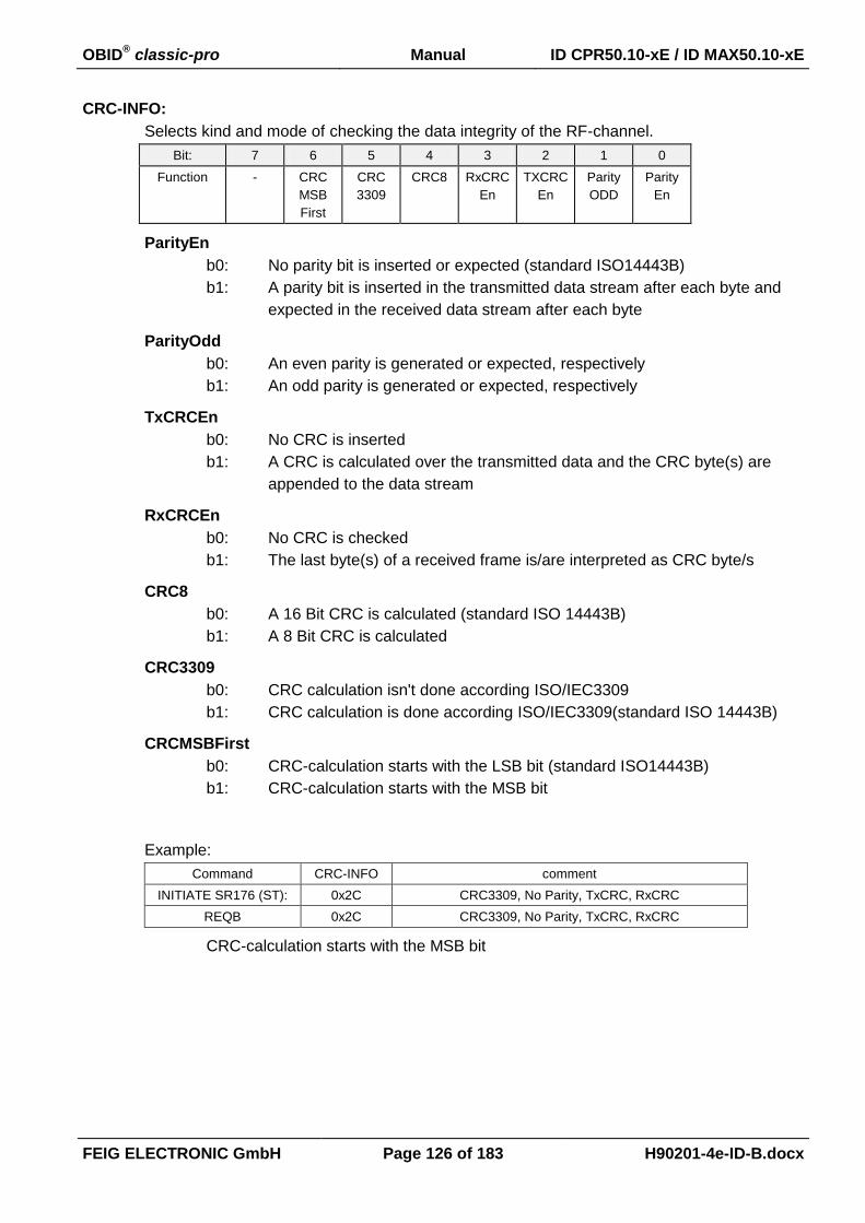
OBID® classic-pro Manual ID CPR50.10-xE / ID MAX50.10-xE
FEIG ELECTRONIC GmbH Page 126 of 183 H90201-4e-ID-B.docx
CRC-INFO:
Selects kind and mode of checking the data integrity of the RF-channel.
Bit: 7 6 5 4 3 2 1 0
Function - CRC
MSB
First
CRC
3309
CRC8 RxCRC
En
TXCRC
En
Parity
ODD
Parity
En
ParityEn
b0: No parity bit is inserted or expected (standard ISO14443B)
b1: A parity bit is inserted in the transmitted data stream after each byte and
expected in the received data stream after each byte
ParityOdd
b0: An even parity is generated or expected, respectively
b1: An odd parity is generated or expected, respectively
TxCRCEn
b0: No CRC is inserted
b1: A CRC is calculated over the transmitted data and the CRC byte(s) are
appended to the data stream
RxCRCEn
b0: No CRC is checked
b1: The last byte(s) of a received frame is/are interpreted as CRC byte/s
CRC8
b0: A 16 Bit CRC is calculated (standard ISO 14443B)
b1: A 8 Bit CRC is calculated
CRC3309
b0: CRC calculation isn't done according ISO/IEC3309
b1: CRC calculation is done according ISO/IEC3309(standard ISO 14443B)
CRCMSBFirst
b0: CRC-calculation starts with the LSB bit (standard ISO14443B)
b1: CRC-calculation starts with the MSB bit
Example:
Command CRC-INFO comment
INITIATE SR176 (ST): 0x2C CRC3309, No Parity, TxCRC, RxCRC
REQB 0x2C CRC3309, No Parity, TxCRC, RxCRC
CRC-calculation starts with the MSB bit

OBID® classic-pro Manual ID CPR50.10-xE / ID MAX50.10-xE
FEIG ELECTRONIC GmbH Page 127 of 183 H90201-4e-ID-B.docx
TX-SETTINGS:
Selects kind and mode of transmission settings.
Bit: 7 6 5 4 3 2 1 0
Function - - - - - - BAUDRATE
BAUDRATE
b00: 106 kBaud
b01: 212 kBaud
b10: 424 kBaud
b11: 848 kBaud
RX-SETTINGS:
Selects kind and mode of reception settings.
Bit: 7 6 5 4 3 2 1 0
Function - - - - - - BAUDRATE
BAUDRATE
b00: 106 kBaud
b01: 212 kBaud
b10: 424 kBaud
b11: 848 kBaud
REQ-BITS:
Number of valid bits in REQUEST-DATA.
REQUEST-DATA:
Complete transponder request without SOF and EOF. If “TxCRCEn” is “1” the reader ap-
pended a calculated CRC to the date stream. If “TxCRCEn” is “0” the application should
send the CRC within the Request-Data, if the CRC is needed.
NOTICE:
The max. size of REQUEST-DATA is 64 Byte
RESPONSE-DATA:
Complete transponder response without SOF and EOF. A CRC check is performed inside
the reader if “RxCRCEn” is “1”. However if “RxCRCEn” is “0” the transponder CRC is
transferred with the response data.
NOTICE:
Data is only transferred if STATUS = 0x00, 0x02, 0x83, 0x84, 0x94.
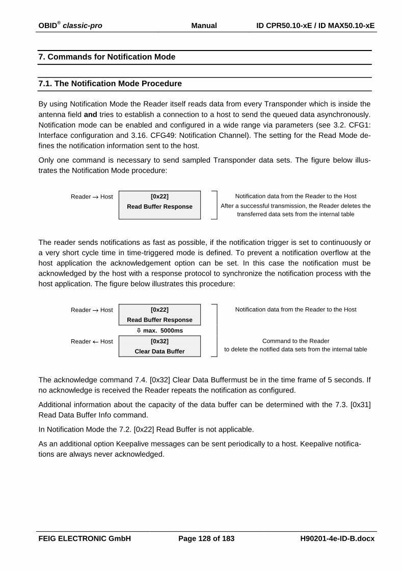
OBID® classic-pro Manual ID CPR50.10-xE / ID MAX50.10-xE
FEIG ELECTRONIC GmbH Page 128 of 183 H90201-4e-ID-B.docx
7. Commands for Notification Mode
7.1. The Notification Mode Procedure
By using Notification Mode the Reader itself reads data from every Transponder which is inside the
antenna field and tries to establish a connection to a host to send the queued data asynchronously.
Notification mode can be enabled and configured in a wide range via parameters (see 3.2. CFG1:
Interface configuration and 3.16. CFG49: Notification Channel). The setting for the Read Mode de-
fines the notification information sent to the host.
Only one command is necessary to send sampled Transponder data sets. The figure below illus-
trates the Notification Mode procedure:
Reader Host [0x22]
Read Buffer Response
Notification data from the Reader to the Host
After a successful transmission, the Reader deletes the
transferred data sets from the internal table
The reader sends notifications as fast as possible, if the notification trigger is set to continuously or
a very short cycle time in time-triggered mode is defined. To prevent a notification overflow at the
host application the acknowledgement option can be set. In this case the notification must be
acknowledged by the host with a response protocol to synchronize the notification process with the
host application. The figure below illustrates this procedure:
Reader Host [0x22]
Read Buffer Response
Notification data from the Reader to the Host
max. 5000ms
Reader Host [0x32]
Clear Data Buffer
Command to the Reader
to delete the notified data sets from the internal table
The acknowledge command 7.4. [0x32] Clear Data Buffermust be in the time frame of 5 seconds. If
no acknowledge is received the Reader repeats the notification as configured.
Additional information about the capacity of the data buffer can be determined with the 7.3. [0x31]
Read Data Buffer Info command.
In Notification Mode the 7.2. [0x22] Read Buffer is not applicable.
As an additional option Keepalive messages can be sent periodically to a host. Keepalive notifica-
tions are always never acknowledged.

OBID® classic-pro Manual ID CPR50.10-xE / ID MAX50.10-xE
FEIG ELECTRONIC GmbH Page 129 of 183 H90201-4e-ID-B.docx
7.2. [0x22] Read Buffer
The Read Buffer Command has two functions. It can be used to poll data sets from the internal noti-
fication data buffer.
In notification mode the reader transmits the data self initialized by using the response of the Read
Buffer command.
Host Reader
1 2 3 4 .. 5 6...7
7 COM-ADR [0x22] DATA-SETS CRC16
Host Reader
1 2 3 4 5 (6) 6, 7 (7, 8)
n COM-ADR [0x22] STATUS1 TR-DATA1 TR-DATA2 DATA-SETS
(8 or 9 ... n-2) n-1, n
DATA CRC16
DATA-SETS:
Number of data sets to be transferred from the data buffer. If the data buffer does not con-
tain the requested number of data sets, the Reader responds with all available data sets
and an error will occur.
TR-DATA1:
Indicates the content of the following data.
Bit: 7 6 5 4 3 2 1 0
Function Exten-
sion
- - - Byte Or-
der
- DB UID
UID:
Transponder serial number
DB:
data block
Byte Order:
b0: MSB first
b1: LSB first
Extension:
If this bit is set TR-DATA2 is present
1 see ANNEX C: Index of Status Bytes

OBID® classic-pro Manual ID CPR50.10-xE / ID MAX50.10-xE
FEIG ELECTRONIC GmbH Page 130 of 183 H90201-4e-ID-B.docx
TR-DATA2:
Selects the data types for read operation.
Bit: 7 6 5 4 3 2 1 0
Function - - - - - - MAC -
MAC:
MAC-Address
DATA:
Requested number of data sets from the data buffer. Only selected data will be transferred
to the host. See chapter 3.8. CFG11: Read Mode for details. Each data set has the follow-
ing structure:
Data Type DATA
Record Length byte no. 1 2
MSB RecLen LSB RecLen
Serial Number byte no. 1 2 3 3+LEN
TR-TYP TR_INFO UID-LEN UID
Data Blocks byte no. 1 2 3 4…4+DB-N*DB-SIZE
DB-N DB-SIZE DB
MAC-Address byte no. 1…6
MAC
TR-TYPE:
see 6.1.1. [0x01] Inventory.
TR_INFO (only ISO 14443A):
see 6.1.1.1. Response-Data - ISO 14443A (TR-TYPE = 0x04).
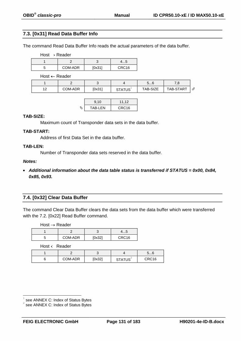
OBID® classic-pro Manual ID CPR50.10-xE / ID MAX50.10-xE
FEIG ELECTRONIC GmbH Page 131 of 183 H90201-4e-ID-B.docx
7.3. [0x31] Read Data Buffer Info
The command Read Data Buffer Info reads the actual parameters of the data buffer.
Host Reader
1 2 3 4...5
5 COM-ADR [0x31] CRC16
Host Reader
1 2 3 4 5...6 7,8
12 COM-ADR [0x31] STATUS1 TAB-SIZE TAB-START
9,10 11,12
TAB-LEN CRC16
TAB-SIZE:
Maximum count of Transponder data sets in the data buffer.
TAB-START:
Address of first Data Set in the data buffer.
TAB-LEN:
Number of Transponder data sets reserved in the data buffer.
Notes:
Additional information about the data table status is transferred if STATUS = 0x00, 0x84,
0x85, 0x93.
7.4. [0x32] Clear Data Buffer
The command Clear Data Buffer clears the data sets from the data buffer which were transferred
with the 7.2. [0x22] Read Buffer command.
Host Reader
1 2 3 4...5
5 COM-ADR [0x32] CRC16
Host Reader
1 2 3 4 5...6
6 COM-ADR [0x32] STATUS2 CRC16
1 see ANNEX C: Index of Status Bytes 2 see ANNEX C: Index of Status Bytes

OBID® classic-pro Manual ID CPR50.10-xE / ID MAX50.10-xE
FEIG ELECTRONIC GmbH Page 132 of 183 H90201-4e-ID-B.docx
7.5. [0x33] Initialize Buffer
The command Initialize Buffer clears the data buffer to an initial state. It does not matter if the data
sets in the data buffer were read or not.
Host Reader
1 2 3 4...5
5 COM-ADR [0x33] CRC16
Host Reader
1 2 3 4 5...6
6 COM-ADR [0x33] STATUS1
CRC16
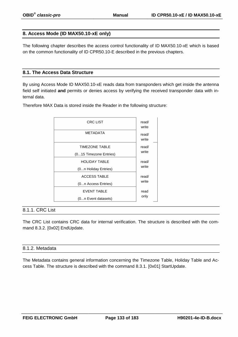
OBID® classic-pro Manual ID CPR50.10-xE / ID MAX50.10-xE
FEIG ELECTRONIC GmbH Page 133 of 183 H90201-4e-ID-B.docx
8. Access Mode (ID MAX50.10-xE only)
The following chapter describes the access control functionality of ID MAX50.10-xE which is based
on the common functionality of ID CPR50.10-E described in the previous chapters.
8.1. The Access Data Structure
By using Access Mode ID MAX50.10-xE reads data from transponders which get inside the antenna
field self initiated and permits or denies access by verifying the received transponder data with in-
ternal data.
Therefore MAX Data is stored inside the Reader in the following structure:
CRC LIST read/
write
METADATA read/
write
TIMEZONE TABLE
(0...15 Timezone Entries)
read/
write
HOLIDAY TABLE
(0...n Holiday Entries)
read/
write
ACCESS TABLE
(0...n Access Entries)
read/
write
EVENT TABLE
(0...n Event datasets)
read
only
8.1.1. CRC List
The CRC List contains CRC data for internal verification. The structure is described with the com-
mand 8.3.2. [0x02] EndUpdate.
8.1.2. Metadata
The Metadata contains general information concerning the Timezone Table, Holiday Table and Ac-
cess Table. The structure is described with the command 8.3.1. [0x01] StartUpdate.

OBID® classic-pro Manual ID CPR50.10-xE / ID MAX50.10-xE
FEIG ELECTRONIC GmbH Page 134 of 183 H90201-4e-ID-B.docx
8.1.3. Timezone Table
The Timezone Table is a list of Timezone Entries to permit access during the user defined timezone.
The entries are callable by their index starting with 0. The timezone table index 15 is not user defin-
able and permits permanent access.
TIMEZONE TABE INDEX
0...14 user defined TIMEZONE ENTRY
15 permits permanent access
TIMEZONE TABLE ENTRY:
Byte 0...3 3...5 6 7+8 9+10
Content STARTDATE
OF VALIDITY
ENDDATE OF
VALIDITY
DAYS OF
VALIDITY
STARTTIME
OF VALIDITY
ENDTIME OF
VALIDITY
STARTDATE OF VALIDITY:
This parameter defines the startdate for possible access.
Byte 0 1 2
Content STARTDAY OF
VALIDITY
STARTMONTH
OF VALIDITY
STARTYEAR OF
VALIDITY
1...31 1...12 00...99
ENDDATE OF VALIDITY:
This parameter defines the enddate for possible access.
Byte 0 1 2
Content ENDDAY OF
VALIDITY
ENDMONTH OF
VALIDITY
ENDYEAR OF
VALIDITY
1...31 1...12 00...99
DAYS OF VALIDITY:
This parameter defines the weekdays for possible access.
Bit: 7 6 5 4 3 2 1 0
Function b0 Sa Fr Th We Tu Mo Su
b0: Access denied for the specific weekday
b1: Access permitted for the specific weekday

OBID® classic-pro Manual ID CPR50.10-xE / ID MAX50.10-xE
FEIG ELECTRONIC GmbH Page 135 of 183 H90201-4e-ID-B.docx
STARTTIME OF VALIDITY:
This parameter defines the daily starttime for possible access.
Byte 0 1
Content STARTHOUR
OF VALIDITY
STARTMINUTE
OF VALIDITY
0...23 0...59
ENDTIME OF VALIDITY:
This parameter defines the daily endtime for possible access.
Byte 0 1
Content ENDHOUR OF
VALIDITY
ENDMINUTE OF
VALIDITY
0...23 0...59
Notes:
A value of 0xFF in any Byte of the Timezone Entry is treaded as don’t care for the specific
field.
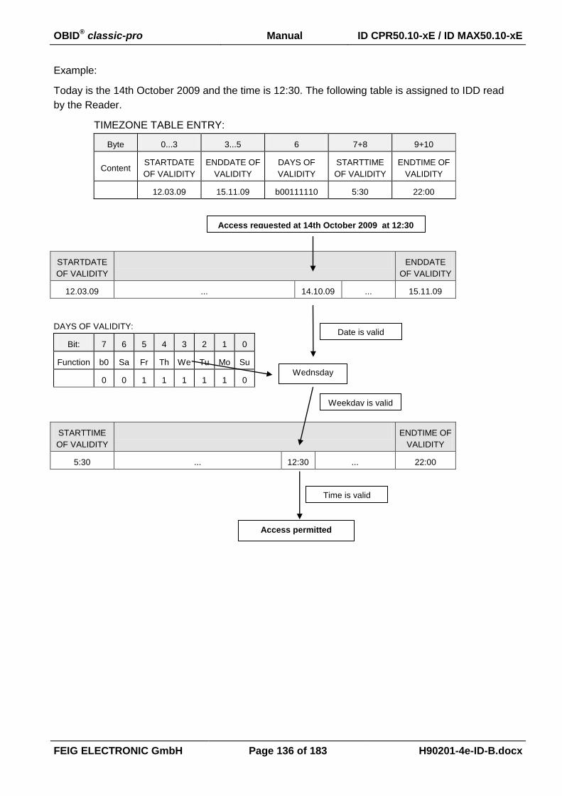
OBID® classic-pro Manual ID CPR50.10-xE / ID MAX50.10-xE
FEIG ELECTRONIC GmbH Page 136 of 183 H90201-4e-ID-B.docx
Example:
Today is the 14th October 2009 and the time is 12:30. The following table is assigned to IDD read
by the Reader.
TIMEZONE TABLE ENTRY:
Byte 0...3 3...5 6 7+8 9+10
Content STARTDATE
OF VALIDITY
ENDDATE OF
VALIDITY
DAYS OF
VALIDITY
STARTTIME
OF VALIDITY
ENDTIME OF
VALIDITY
12.03.09 15.11.09 b00111110 5:30 22:00
STARTDATE
OF VALIDITY
ENDDATE
OF VALIDITY
12.03.09 ... 14.10.09 ... 15.11.09
DAYS OF VALIDITY:
Bit: 7 6 5 4 3 2 1 0
Function b0 Sa Fr Th We Tu Mo Su
0 0 1 1 1 1 1 0
STARTTIME
OF VALIDITY
ENDTIME OF
VALIDITY
5:30 ... 12:30 ... 22:00
Date is valid
Wednsday
Weekday is valid
Time is valid
Access permitted
Access requested at 14th October 2009 at 12:30

OBID® classic-pro Manual ID CPR50.10-xE / ID MAX50.10-xE
FEIG ELECTRONIC GmbH Page 137 of 183 H90201-4e-ID-B.docx
8.1.4. Holiday Table
A list of Holidays that should have the same access permission as Sundays. The first entry has the
index 0. A maximum number of 255 Holidays can be de defined.
HOLIDAY TABLE ENTRY:
This parameter defined the date of a holiday.
Byte 0 1 2
Contents DAY OF
HOLIDAY
MONTH OF
HOLIDAY
YEAR OF
HOLIDAY
1...31 1...12 00...99
8.1.5. Access Table
A list of Access Entries to permit access for a user defined Identifier Data during the selected
Timezones. It is possible to add up to 65535 Access Entries.
ACCESS ENTRY:
Byte 0...n 2 byte 1 byte
Contents IDD Timezones Reserved
IDD:
Identifier Data (max. 64 byte - LSB first)
Notes:
All Identifier Data must have the same length defined in the Metadata.
The access table has to be sorted by the Identifier Data starting with the lowest
value. Therefore the Identifier Data is interpreted as a numeric data.
It is possible to use serial number or data blocks as Identifier Data for Configura-
tion see 8.4.2. CFG11: Read Mode – Read Data 1.
TIMEZONES:
Bit 15 14 13 12 11 10 9 8 7 6 5 4 3 2 1 0
Function
Each bit represents an index into the Timezone Table. To permit access during a
specified time the bit must be set. If bit 15 is set permanent access is permitted.
Reserved:
Reserved for future use.

OBID® classic-pro Manual ID CPR50.10-xE / ID MAX50.10-xE
FEIG ELECTRONIC GmbH Page 138 of 183 H90201-4e-ID-B.docx
8.1.6. Event Table
The Event Table contains the event datasets. The structure is described with the command 8.3.4.
[0x05] Read Table.

OBID® classic-pro Manual ID CPR50.10-xE / ID MAX50.10-xE
FEIG ELECTRONIC GmbH Page 139 of 183 H90201-4e-ID-B.docx
8.2. The Access Mode Procedure
To Exchange Access data with the Reader the MAX Data Exchange Protocol is used. This Protocol
is defined for transfer of block oriented data from host to a device or device to host.
The main task of the protocol is the update process of table data.
Host Reader [0x1F] [0x01]
UpdateStart
Command to the Reader
to activate the update process and
to delete the internal Event Table buffer
Host Reader: Status = OK
Reader responses with package size and timeout
and is ready to receive table data
.
Host Reader [0x1F] [0x03]
WriteTable
Command cycles to the Reader
with table data
Host Reader: Status = OK
Repeated for each table type
.
Host Reader [0x1F] [0x02]
UpdateEnd
Command to the Reader
to signal the end of update process and
to check the checksum of all tables
Host Reader Status = OK Reader is updated successfully
A second task is the read of MAX Data.
Host Reader [0x1F] [0x05]
ReadTable
Command to the Reader
to read data of one table
Host Reader: Status = OK
or
Status = MORE
Reader responses with all available datasets
that can be transmitted in one cycle.
If more datasets are available the Status is MORE.
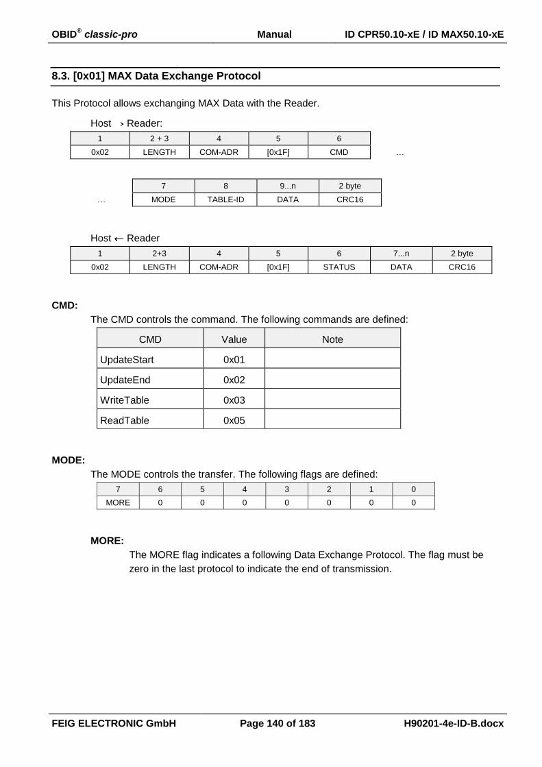
OBID® classic-pro Manual ID CPR50.10-xE / ID MAX50.10-xE
FEIG ELECTRONIC GmbH Page 140 of 183 H90201-4e-ID-B.docx
8.3. [0x01] MAX Data Exchange Protocol
This Protocol allows exchanging MAX Data with the Reader.
Host Reader:
1 2 + 3 4 5 6
0x02 LENGTH COM-ADR [0x1F] CMD …
7 8 9...n 2 byte
… MODE TABLE-ID DATA CRC16
Host Reader
1 2+3 4 5 6 7...n 2 byte
0x02 LENGTH COM-ADR [0x1F] STATUS DATA CRC16
CMD:
The CMD controls the command. The following commands are defined:
CMD Value Note
UpdateStart 0x01
UpdateEnd 0x02
WriteTable 0x03
ReadTable 0x05
MODE:
The MODE controls the transfer. The following flags are defined:
7 6 5 4 3 2 1 0
MORE 0 0 0 0 0 0 0
MORE:
The MORE flag indicates a following Data Exchange Protocol. The flag must be
zero in the last protocol to indicate the end of transmission.
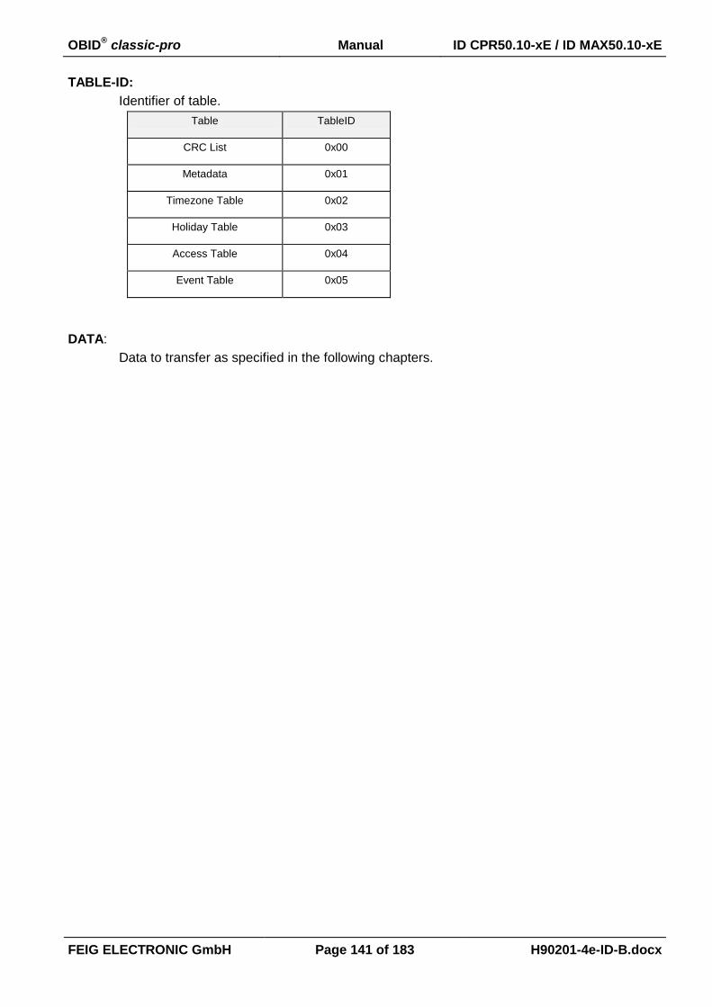
OBID® classic-pro Manual ID CPR50.10-xE / ID MAX50.10-xE
FEIG ELECTRONIC GmbH Page 141 of 183 H90201-4e-ID-B.docx
TABLE-ID:
Identifier of table.
Table TableID
CRC List 0x00
Metadata 0x01
Timezone Table 0x02
Holiday Table 0x03
Access Table 0x04
Event Table 0x05
DATA:
Data to transfer as specified in the following chapters.

OBID® classic-pro Manual ID CPR50.10-xE / ID MAX50.10-xE
FEIG ELECTRONIC GmbH Page 142 of 183 H90201-4e-ID-B.docx
8.3.1. [0x01] StartUpdate
This command activates the update table process and must be therefore the first command in the
command sequence. With this command the internal Event Table is deleted if the responded Status
from the Reader is OK.
Host Reader:
1 2 + 3 4 5 6
0x02 LENGTH COM-ADR [0x1F] 0x01 …
7 8 9...n 2 byte
… 0x00 0x01 METADATA CRC16
Host Reader
1 2+3 4 5 6 7... 2 byte
0x02 LENGTH COM-ADR [0x1F] STATUS RSP-DATA CRC16
METADATA:
General information concerning the Timezone Table, Holiday Table and Access Table:
Byte 0+1 2 3 4+5 6 7
Content TABLE-
VERSION
TIMEZONE-
ENTRIES
HOLIDAY-
ENTRIES
ACCESS-
ENTRIES IDD-LENGTH IDD-FORMAT
0...15 0...255 0...65535 1...64
Byte 8...15
Content reserved
TABLE-VERSION:
Defines the Table-Version. Only Version 0x00 defined.
TIMEZONE-ENTRIES:
Defines the number of valid Timezone Entries inside the Timezone Table. The
maximum value is 15.
HOLIDAY-ENTRIES:
Defines the number of valid Holiday Entries inside the Holiday Table. The maxi-
mum value is 255.
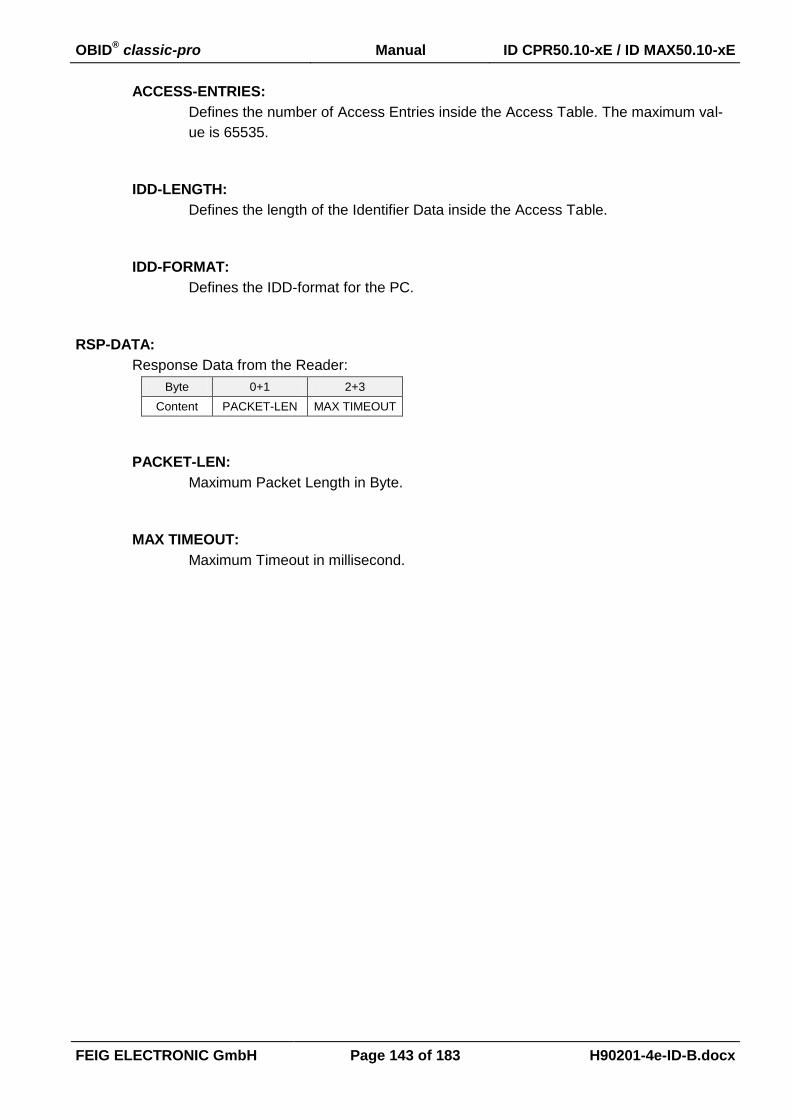
OBID® classic-pro Manual ID CPR50.10-xE / ID MAX50.10-xE
FEIG ELECTRONIC GmbH Page 143 of 183 H90201-4e-ID-B.docx
ACCESS-ENTRIES:
Defines the number of Access Entries inside the Access Table. The maximum val-
ue is 65535.
IDD-LENGTH:
Defines the length of the Identifier Data inside the Access Table.
IDD-FORMAT:
Defines the IDD-format for the PC.
RSP-DATA:
Response Data from the Reader:
Byte 0+1 2+3
Content PACKET-LEN MAX TIMEOUT
PACKET-LEN:
Maximum Packet Length in Byte.
MAX TIMEOUT:
Maximum Timeout in millisecond.
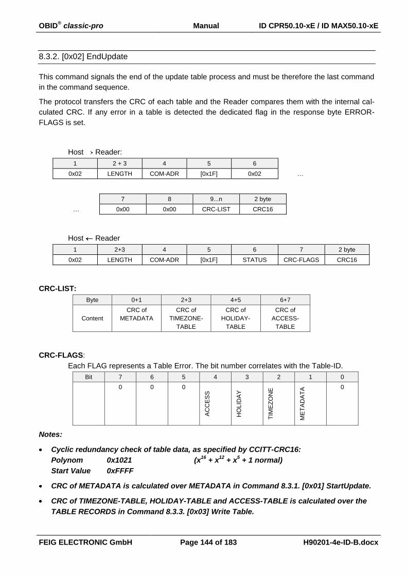
OBID® classic-pro Manual ID CPR50.10-xE / ID MAX50.10-xE
FEIG ELECTRONIC GmbH Page 144 of 183 H90201-4e-ID-B.docx
8.3.2. [0x02] EndUpdate
This command signals the end of the update table process and must be therefore the last command
in the command sequence.
The protocol transfers the CRC of each table and the Reader compares them with the internal cal-
culated CRC. If any error in a table is detected the dedicated flag in the response byte ERROR-
FLAGS is set.
Host Reader:
1 2 + 3 4 5 6
0x02 LENGTH COM-ADR [0x1F] 0x02 …
7 8 9...n 2 byte
… 0x00 0x00 CRC-LIST CRC16
Host Reader
1 2+3 4 5 6 7 2 byte
0x02 LENGTH COM-ADR [0x1F] STATUS CRC-FLAGS CRC16
CRC-LIST:
Byte 0+1 2+3 4+5 6+7
Content
CRC of
METADATA
CRC of
TIMEZONE-
TABLE
CRC of
HOLIDAY-
TABLE
CRC of
ACCESS-
TABLE
CRC-FLAGS:
Each FLAG represents a Table Error. The bit number correlates with the Table-ID.
Bit 7 6 5 4 3 2 1 0
0 0 0
AC
CE
SS
HO
LID
AY
TIM
EZ
ON
E
ME
TA
DA
TA
0
Notes:
Cyclic redundancy check of table data, as specified by CCITT-CRC16:
Polynom 0x1021 (x16
+ x12
+ x5 + 1 normal)
Start Value 0xFFFF
CRC of METADATA is calculated over METADATA in Command 8.3.1. [0x01] StartUpdate.
CRC of TIMEZONE-TABLE, HOLIDAY-TABLE and ACCESS-TABLE is calculated over the
TABLE RECORDS in Command 8.3.3. [0x03] Write Table.
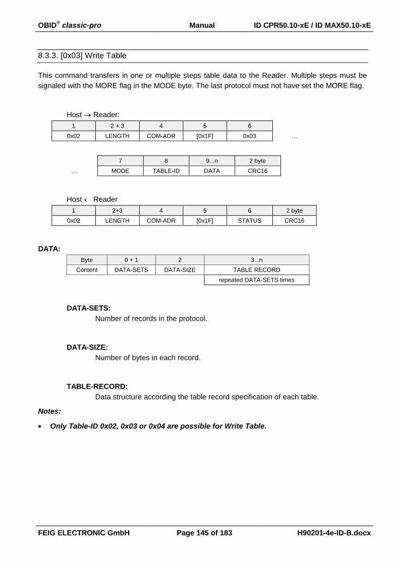
OBID® classic-pro Manual ID CPR50.10-xE / ID MAX50.10-xE
FEIG ELECTRONIC GmbH Page 145 of 183 H90201-4e-ID-B.docx
8.3.3. [0x03] Write Table
This command transfers in one or multiple steps table data to the Reader. Multiple steps must be
signaled with the MORE flag in the MODE byte. The last protocol must not have set the MORE flag.
Host Reader:
1 2 + 3 4 5 6
0x02 LENGTH COM-ADR [0x1F] 0x03 …
7 8 9...n 2 byte
… MODE TABLE-ID DATA CRC16
Host Reader
1 2+3 4 5 6 2 byte
0x02 LENGTH COM-ADR [0x1F] STATUS CRC16
DATA:
Byte 0 + 1 2 3...n
Content DATA-SETS DATA-SIZE TABLE RECORD
repeated DATA-SETS times
DATA-SETS:
Number of records in the protocol.
DATA-SIZE:
Number of bytes in each record.
TABLE-RECORD:
Data structure according the table record specification of each table.
Notes:
Only Table-ID 0x02, 0x03 or 0x04 are possible for Write Table.
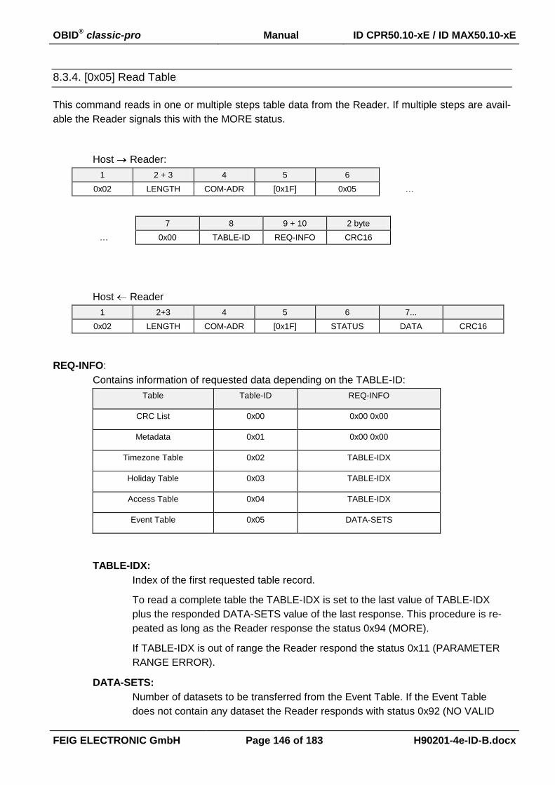
OBID® classic-pro Manual ID CPR50.10-xE / ID MAX50.10-xE
FEIG ELECTRONIC GmbH Page 146 of 183 H90201-4e-ID-B.docx
8.3.4. [0x05] Read Table
This command reads in one or multiple steps table data from the Reader. If multiple steps are avail-
able the Reader signals this with the MORE status.
Host Reader:
1 2 + 3 4 5 6
0x02 LENGTH COM-ADR [0x1F] 0x05 …
7 8 9 + 10 2 byte
… 0x00 TABLE-ID REQ-INFO CRC16
Host Reader
1 2+3 4 5 6 7...
0x02 LENGTH COM-ADR [0x1F] STATUS DATA CRC16
REQ-INFO:
Contains information of requested data depending on the TABLE-ID:
Table Table-ID REQ-INFO
CRC List 0x00 0x00 0x00
Metadata 0x01 0x00 0x00
Timezone Table 0x02 TABLE-IDX
Holiday Table 0x03 TABLE-IDX
Access Table 0x04 TABLE-IDX
Event Table 0x05 DATA-SETS
TABLE-IDX:
Index of the first requested table record.
To read a complete table the TABLE-IDX is set to the last value of TABLE-IDX
plus the responded DATA-SETS value of the last response. This procedure is re-
peated as long as the Reader response the status 0x94 (MORE).
If TABLE-IDX is out of range the Reader respond the status 0x11 (PARAMETER
RANGE ERROR).
DATA-SETS:
Number of datasets to be transferred from the Event Table. If the Event Table
does not contain any dataset the Reader responds with status 0x92 (NO VALID

OBID® classic-pro Manual ID CPR50.10-xE / ID MAX50.10-xE
FEIG ELECTRONIC GmbH Page 147 of 183 H90201-4e-ID-B.docx
DATA). If the Event Table does not contain the requested number of datasets, the
Reader responds with all available datasets. If more datasets are available, the
Reader responds with status 0x94 (MORE). The read datasets of the Event Table
are deleted.
DATA:
TABLE-ID = {0x00, 0x01, 0x02, 0x03, 0x04}
Byte 0 + 1 2 3...n
Content DATA-SETS DATA-SIZE TABLE RECORD
repeated DATA-SETS times
DATA-SETS:
Number of records in the protocol.
DATA-SIZE:
Number of bytes in each record.
TABLE-RECORD:
Data structure according the table Record specification of each table.
DATA:
TABLE-ID = {0x05}
Byte 0 1 + 2 3...n
Content DATA-LAYOUT DATA-SETS EVENT RECORD
repeated DATA-SETS times
DATA-LAYOUT:
Defines the layout of each event record. Each flag signals the inclusion of the data
section selected by the parameter EVENT-OPT in 8.4.3. CFG14: Access Control.
Bit: 7 6 5 4 3 2 1 0
Function 0 0 0 0 INPUT
DATA
EVENT
STATUS
TIME-
STAMP IDD SET
IDD SET: Identifier Data Set
TIMESTAMP: internal system date and time
EVENT STATUS: Access action and additional error code
INPUT DATA: Input status
DATA-SETS:
Number of records in the protocol.

OBID® classic-pro Manual ID CPR50.10-xE / ID MAX50.10-xE
FEIG ELECTRONIC GmbH Page 148 of 183 H90201-4e-ID-B.docx
EVENT RECORD:
Event record with different data sections:
Data Section DATA
Record Length byte no. 1 2
MSB RecLen LSB RecLen
EVENT-ID byte no. 1
EVENT-ID
IDD SET byte no. 1 2..2+IDD-LEN
IDD-LEN IDD
TIMESTAMP byte no. 1...3 4...6
DATE TIME
EVENT STATUS byte no. 1 2...3
ACTION ERROR
INPUT DATA byte no. 1
INPUT
EVENT-ID:
Number of Event type:
Event Type Event-ID
Access event 0x01
Input event 0x02
IDD-LENGTH:
Length of the Identifier Data in byte (max. 16 byte)
IDD:
Identifier Data (max. 16 byte)
DATE:
Byte 0 1 3
Contents DAY MONTH YEAR
1...31 1...12 0...99
TIME:
Byte 0 1 2
Contents HOUR MINUTE SECOND
0...23 0...59 0...59
ACTION:
Bit 7 6 5 4 3 2 1 0

OBID® classic-pro Manual ID CPR50.10-xE / ID MAX50.10-xE
FEIG ELECTRONIC GmbH Page 149 of 183 H90201-4e-ID-B.docx
Fu
nctio
n 0 0 0 0 0 0 0
Acce
ss
Access:
b0: Denied access
b1: Permitted access
ERROR:
Each FLAG represents an Error.
Bit 15 14 13 12 11 10 9 8
Fu
nctio
n
OV
ER
FL
OW
0 0 0 0 0 0 0
Bit 7 6 5 4 3 2 1 0
Fu
nctio
n
TA
BL
E
UP
DA
TE
BU
SY
RE
AD
ER
CO
NF
IG 0
AC
CE
SS
HO
LID
AY
TIM
EZ
ON
E
ME
TA
DA
TA
RT
C
INPUT:
Bit 7 6 5 4 3 2 1 0
Fu
nctio
n 0 0 0 0
IN3
IN3
IN2
IN1
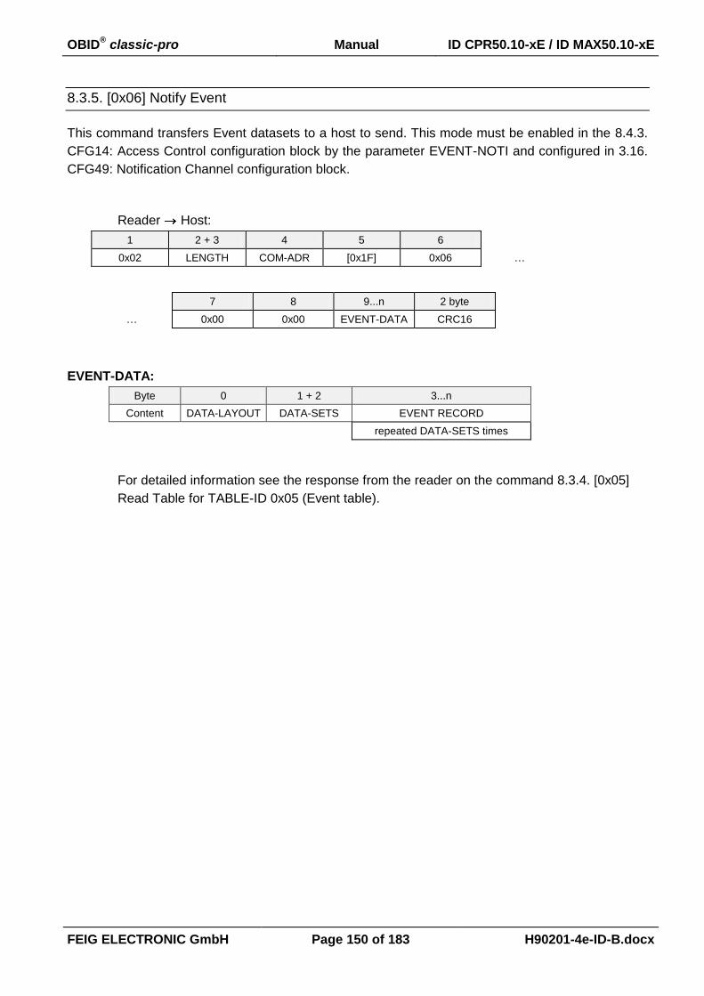
OBID® classic-pro Manual ID CPR50.10-xE / ID MAX50.10-xE
FEIG ELECTRONIC GmbH Page 150 of 183 H90201-4e-ID-B.docx
8.3.5. [0x06] Notify Event
This command transfers Event datasets to a host to send. This mode must be enabled in the 8.4.3.
CFG14: Access Control configuration block by the parameter EVENT-NOTI and configured in 3.16.
CFG49: Notification Channel configuration block.
Reader Host:
1 2 + 3 4 5 6
0x02 LENGTH COM-ADR [0x1F] 0x06 …
7 8 9...n 2 byte
… 0x00 0x00 EVENT-DATA CRC16
EVENT-DATA:
Byte 0 1 + 2 3...n
Content DATA-LAYOUT DATA-SETS EVENT RECORD
repeated DATA-SETS times
For detailed information see the response from the reader on the command 8.3.4. [0x05]
Read Table for TABLE-ID 0x05 (Event table).
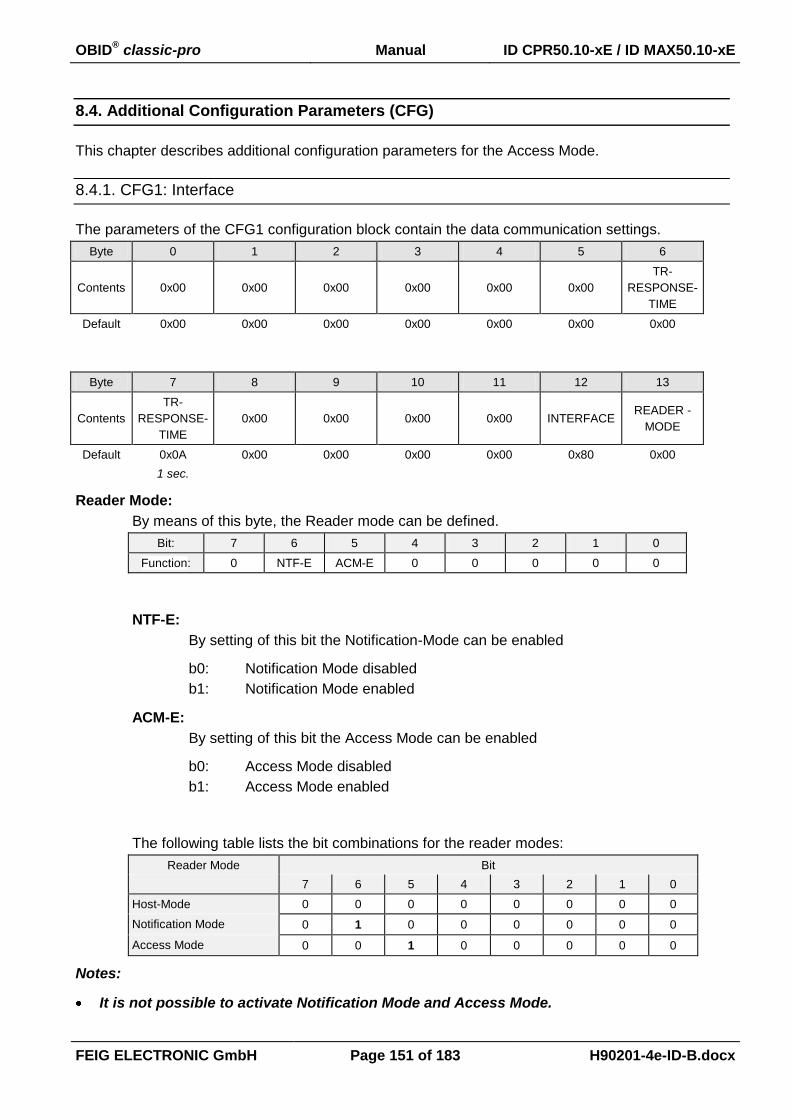
OBID® classic-pro Manual ID CPR50.10-xE / ID MAX50.10-xE
FEIG ELECTRONIC GmbH Page 151 of 183 H90201-4e-ID-B.docx
8.4. Additional Configuration Parameters (CFG)
This chapter describes additional configuration parameters for the Access Mode.
8.4.1. CFG1: Interface
The parameters of the CFG1 configuration block contain the data communication settings.
Byte 0 1 2 3 4 5 6
Contents 0x00 0x00 0x00 0x00
0x00
0x00
TR-
RESPONSE-
TIME
Default 0x00 0x00 0x00 0x00 0x00 0x00 0x00
Byte 7 8 9 10 11 12 13
Contents
TR-
RESPONSE-
TIME
0x00 0x00 0x00 0x00 INTERFACE READER -
MODE
Default 0x0A 0x00 0x00 0x00 0x00 0x80 0x00
1 sec.
Reader Mode:
By means of this byte, the Reader mode can be defined.
Bit: 7 6 5 4 3 2 1 0
Function: 0 NTF-E ACM-E 0 0 0 0 0
NTF-E:
By setting of this bit the Notification-Mode can be enabled
b0: Notification Mode disabled
b1: Notification Mode enabled
ACM-E:
By setting of this bit the Access Mode can be enabled
b0: Access Mode disabled
b1: Access Mode enabled
The following table lists the bit combinations for the reader modes:
Reader Mode Bit
7 6 5 4 3 2 1 0
Host-Mode 0 0 0 0 0 0 0 0
Notification Mode 0 1 0 0 0 0 0 0
Access Mode 0 0 1 0 0 0 0 0
Notes:
It is not possible to activate Notification Mode and Access Mode.

OBID® classic-pro Manual ID CPR50.10-xE / ID MAX50.10-xE
FEIG ELECTRONIC GmbH Page 152 of 183 H90201-4e-ID-B.docx
8.4.2. CFG11: Read Mode – Read Data 1
The parameters of the CFG11 configuration block contain Access Mode settings.
Byte 0 1 2 3 4 5 6
Contents TR-DATA-1 TR-DATA-2 0x00 0x00 DB-ADR 1 0x00
Default 0x01 0x00 0x00 0x00 0x0000 0x00
Byte 7 8 9 10 11 12 13
Contents 0x00 DB-N 2 0x00 D-OFFSET D-LENGTH
Default 0x00 0x0001 0x00 0x00 0x04
TR-DATA-1:
Defines the data types for read operation that are used for Identifier data (IDD).
Bit: 7 6 5 4 3 2 1 0
Function 0 0 0 0 Byte
Order
0 DB SNR
SNR:
b0: no Serial Number for Identifier Data
b1: use Serial Number for Identifier Data
DB:
b0: no data block for Identifier Data
b1: use data block for Identifier Data
Byte Order:
By this bit the byte order of the data block can be swapped.
b0: MSB first
b1: LSB first
Notes:
If SNR and DB are used for Identifier Data access is permitted if either SNR or DB
are valid.
TR-DATA-2:
Not used for Identifier data (IDD)..
DB-ADR:
Address of first data block. Range: 0x00...0xFF.
DB-N:
Number of data blocks. Range: 64 Bytes of data.
1 A reasonableness check is performed by writing this parameter to the Reader. If an error occurs the Reader answers with STATUS = [0x11].
2 A plausibility check is performed by writing this parameter to the Reader. If an error occurs the Reader
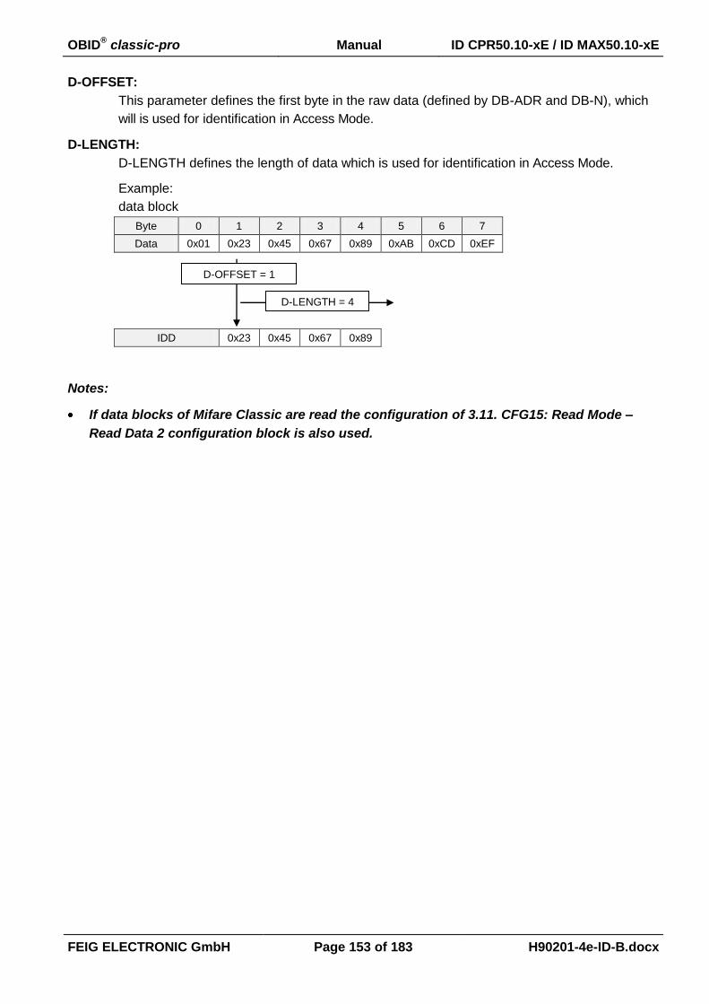
OBID® classic-pro Manual ID CPR50.10-xE / ID MAX50.10-xE
FEIG ELECTRONIC GmbH Page 153 of 183 H90201-4e-ID-B.docx
D-OFFSET:
This parameter defines the first byte in the raw data (defined by DB-ADR and DB-N), which
will is used for identification in Access Mode.
D-LENGTH:
D-LENGTH defines the length of data which is used for identification in Access Mode.
Example:
data block
Byte 0 1 2 3 4 5 6 7
Data 0x01 0x23 0x45 0x67 0x89 0xAB 0xCD 0xEF
IDD 0x23 0x45 0x67 0x89
Notes:
If data blocks of Mifare Classic are read the configuration of 3.11. CFG15: Read Mode –
Read Data 2 configuration block is also used.
D-OFFSET = 1
D-LENGTH = 4
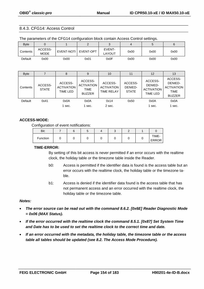
OBID® classic-pro Manual ID CPR50.10-xE / ID MAX50.10-xE
FEIG ELECTRONIC GmbH Page 154 of 183 H90201-4e-ID-B.docx
8.4.3. CFG14: Access Control
The parameters of the CFG14 configuration block contain Access Control settings.
Byte 0 1 2 3 4 5 6
Contents ACCESS-
MODE EVENT-NOTI EVENT-OPT
EVENT-
LAYOUT 0x00 0x00 0x00
Default 0x00 0x00 0x01 0x0F 0x00 0x00 0x00
Byte 7 8 9 10 11 12 13
Contents ACCESS-
STATE
ACCESS-
ACTIVATION
TIME LED
ACCESS-
ACTIVATION
TIME
BUZZER
ACCESS-
ACTIVATION
TIME RELAY
ACCESS-
DENIED-
STATE
ACCESS-
DENIED-
ACTIVATION
TIME LED
ACCESS-
DENIED-
ACTIVATION
TIME
BUZZER
Default 0x41 0x0A 0x0A 0x14 0x50 0x0A 0x0A
1 sec. 1 sec. 2 sec. 1 sec. 1 sec.
ACCESS-MODE:
Configuration of event notifications:
Bit: 7 6 5 4 3 2 1 0
Function 0 0 0 0 0 0 0 TIME-
ERROR
TIME-ERROR:
By setting of this bit access is never permitted if an error occurs with the realtime
clock, the holiday table or the timezone table inside the Reader.
b0: Access is permitted if the identifier data is found is the access table but an
error occurs with the realtime clock, the holiday table or the timezone ta-
ble.
b1: Access is denied if the identifier data found is the access table that has
not permanent access and an error occurred with the realtime clock, the
holiday table or the timezone table.
Notes:
The error source can be read out with the command 8.6.2. [0x6E] Reader Diagnostic Mode
= 0x06 (MAX Status).
If the error occurred with the realtime clock the command 8.5.1. [0x87] Set System Time
and Date has to be used to set the realtime clock to the correct time and date.
If an error occurred with the metadata, the holiday table, the timezone table or the access
table all tables should be updated (see 8.2. The Access Mode Procedure).

OBID® classic-pro Manual ID CPR50.10-xE / ID MAX50.10-xE
FEIG ELECTRONIC GmbH Page 155 of 183 H90201-4e-ID-B.docx
EVENT-NOTI:
Configuration of event notifications:
Bit: 7 6 5 4 3 2 1 0
Function 0 0 0 0 0 0 0 EN
EN:
By setting of this bit the notification of events defined in EVENT-OPT can be ena-
bled or disabled.
b0: Event notifications are disabled. Events are internally recorded and can
be read out by using the command 8.3.4. [0x05] Read Table.
b1: Event notifications are enabled and the reader tries to establish a host
connection immediately otherwise they are recorded internally. The host
connection is configured in 3.16. CFG49: Notification Channel configura-
tion block.
EVENT-OPT:
Different for events can be enabled:
Bit: 7 6 5 4 3 2 1 0
Function 0 0 0 0 0
0
0
AC
CE
SS
-
EV
EN
T
ACCESS-EVENT:
By setting of this bit access events (permissions and denials) can be activated
b0: access events disabled
b1: access events enabled
Notes:
Input Events can be enabled by the parameter INPUT-EVENT in 3.3. CFG2: Inputs / Out-
puts general configuration block.
EVENT-LAYOUT:
By means of this parameter the structure of an event record can be configured.
Layout for events:
Bit: 7 6 5 4 3 2 1 0
Function 0 0 0 0
INP
UT
DA
TA
EV
EN
T
ST
AT
US
TIM
E-
ST
AM
P
IDD
SE
T
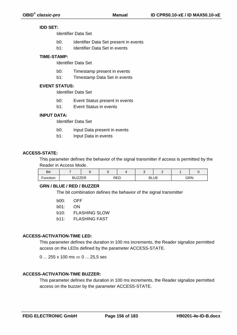
OBID® classic-pro Manual ID CPR50.10-xE / ID MAX50.10-xE
FEIG ELECTRONIC GmbH Page 156 of 183 H90201-4e-ID-B.docx
IDD SET:
Identifier Data Set
b0: Identifier Data Set present in events
b1: Identifier Data Set in events
TIME-STAMP:
Identifier Data Set
b0: Timestamp present in events
b1: Timestamp Data Set in events
EVENT STATUS:
Identifier Data Set
b0: Event Status present in events
b1: Event Status in events
INPUT DATA:
Identifier Data Set
b0: Input Data present in events
b1: Input Data in events
ACCESS-STATE:
This parameter defines the behavior of the signal transmitter if access is permitted by the
Reader in Access Mode.
Bit: 7 6 5 4 3 2 1 0
Function: BUZZER RED BLUE GRN
GRN / BLUE / RED / BUZZER
The bit combination defines the behavior of the signal transmitter
b00: OFF
b01: ON
b10: FLASHING SLOW
b11: FLASHING FAST
ACCESS-ACTIVATION-TIME LED:
This parameter defines the duration in 100 ms increments, the Reader signalize permitted
access on the LEDs defined by the parameter ACCESS-STATE.
0 ... 255 x 100 ms 0 ... 25,5 sec
ACCESS-ACTIVATION-TIME BUZZER:
This parameter defines the duration in 100 ms increments, the Reader signalize permitted
access on the buzzer by the parameter ACCESS-STATE.
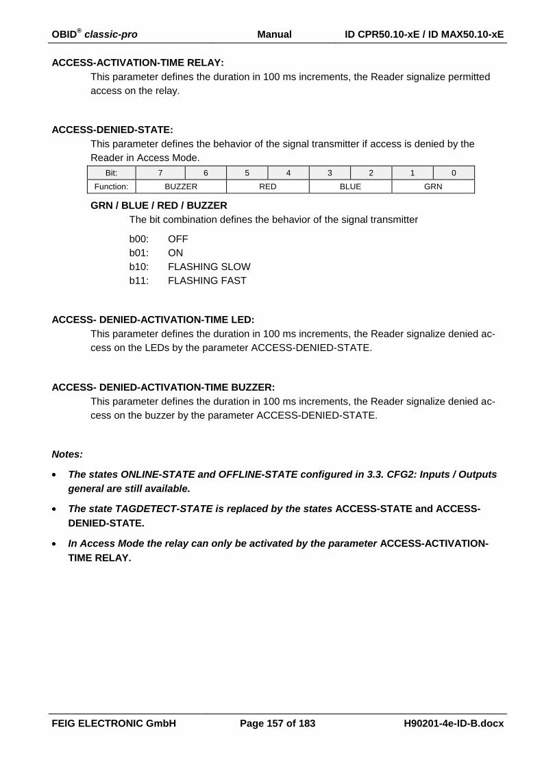
OBID® classic-pro Manual ID CPR50.10-xE / ID MAX50.10-xE
FEIG ELECTRONIC GmbH Page 157 of 183 H90201-4e-ID-B.docx
ACCESS-ACTIVATION-TIME RELAY:
This parameter defines the duration in 100 ms increments, the Reader signalize permitted
access on the relay.
ACCESS-DENIED-STATE:
This parameter defines the behavior of the signal transmitter if access is denied by the
Reader in Access Mode.
Bit: 7 6 5 4 3 2 1 0
Function: BUZZER RED BLUE GRN
GRN / BLUE / RED / BUZZER
The bit combination defines the behavior of the signal transmitter
b00: OFF
b01: ON
b10: FLASHING SLOW
b11: FLASHING FAST
ACCESS- DENIED-ACTIVATION-TIME LED:
This parameter defines the duration in 100 ms increments, the Reader signalize denied ac-
cess on the LEDs by the parameter ACCESS-DENIED-STATE.
ACCESS- DENIED-ACTIVATION-TIME BUZZER:
This parameter defines the duration in 100 ms increments, the Reader signalize denied ac-
cess on the buzzer by the parameter ACCESS-DENIED-STATE.
Notes:
The states ONLINE-STATE and OFFLINE-STATE configured in 3.3. CFG2: Inputs / Outputs
general are still available.
The state TAGDETECT-STATE is replaced by the states ACCESS-STATE and ACCESS-
DENIED-STATE.
In Access Mode the relay can only be activated by the parameter ACCESS-ACTIVATION-
TIME RELAY.
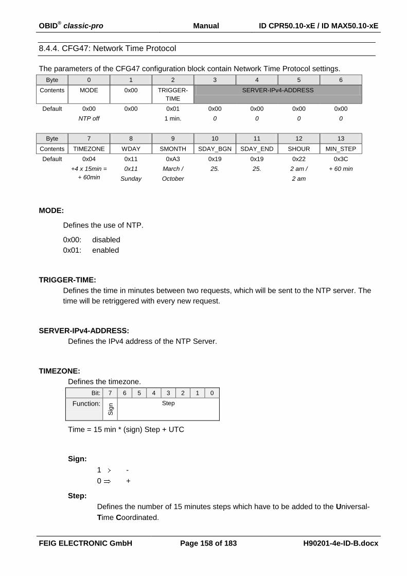
OBID® classic-pro Manual ID CPR50.10-xE / ID MAX50.10-xE
FEIG ELECTRONIC GmbH Page 158 of 183 H90201-4e-ID-B.docx
8.4.4. CFG47: Network Time Protocol
The parameters of the CFG47 configuration block contain Network Time Protocol settings.
Byte 0 1 2 3 4 5 6
Contents MODE 0x00 TRIGGER-
TIME
SERVER-IPv4-ADDRESS
Default 0x00 0x00 0x01 0x00 0x00 0x00 0x00
NTP off 1 min. 0 0 0 0
Byte 7 8 9 10 11 12 13
Contents TIMEZONE WDAY SMONTH SDAY_BGN SDAY_END SHOUR MIN_STEP
Default 0x04 0x11 0xA3 0x19 0x19 0x22 0x3C
+4 x 15min =
+ 60min
0x11
Sunday
March /
October
25. 25. 2 am /
2 am
+ 60 min
MODE:
Defines the use of NTP.
0x00: disabled
0x01: enabled
TRIGGER-TIME:
Defines the time in minutes between two requests, which will be sent to the NTP server. The
time will be retriggered with every new request.
SERVER-IPv4-ADDRESS:
Defines the IPv4 address of the NTP Server.
TIMEZONE:
Defines the timezone.
Bit: 7 6 5 4 3 2 1 0
Function:
Sig
n Step
Time = 15 min * (sign) Step + UTC
Sign:
1 -
0 +
Step:
Defines the number of 15 minutes steps which have to be added to the Universal-
Time Coordinated.

OBID® classic-pro Manual ID CPR50.10-xE / ID MAX50.10-xE
FEIG ELECTRONIC GmbH Page 159 of 183 H90201-4e-ID-B.docx
WDAY:
Together with SDAY_x defines the day of the week or date when the respective change
should occur.
Bit: 7 6 5 4 3 2 1 0
Function: WDAY_END
(0..7)
WDAY_BGN
(0..7)
WDAY_BGN
0 Changeover date is defined by SMONTH_BGN and SDAY_BGN.
1..7 Changeover occurs on a defined day of the week
(1: Sunday, 2: Monday, ....7: Saturday) in the month SMONTH_BGN.
SDAY_BGN defines the time period.
WDAY_END
0 Changeover date is defined by SMONTH_END and SDAY_END.
1..7 Changeover occurs on a defined day of the week
(1: Sunday, 2: Monday, ....7: Saturday) in the month SMONTH_END.
SDAY_END defines the time period.
SMONTH:
Defines the starting month for daylight saving time
Bit: 7 6 5 4 3 2 1 0
Function: SMONTH_END
(0..12)
SMONTH_BGN
(0..12)
SMONTH_BGN
1..12 Defines the starting month for daylight saving time
0 Change disabled
SMONTH_END
1..12 Defines the ending month for daylight saving time
0 Change disabled

OBID® classic-pro Manual ID CPR50.10-xE / ID MAX50.10-xE
FEIG ELECTRONIC GmbH Page 160 of 183 H90201-4e-ID-B.docx
SDAY_BGN / SDAY_END (1...31):
Defines the type of changeover depending on WDAY_BGN and WDAY_END (WDAY_x).
WDAY_x > 0 (weekday changeover):
Changeover occurs on the weekday defined by WDAY which lies between the
days SDAY_x and SDAY_x + 6.
Example:
To have the changeover occur on the last Sunday of a month having 31 days, set
WDAY = 1 (Sunday) and SDAY_x = 25 (31 - 6). The changeover then takes place
on the Sunday which occurs between the 25th and 31st of the month defined by
SMONTH_x.
To have the changeover occur for example on the 1st Friday of a month, set
WDAY = 6 and SDAY_x = 1.
WDAY_x = 0 (Date changeover)
Changeover occurs on the date defined by SMONTH_x and SDAY_x.
SHOUR:
Defines the time of day in full hours between midnight (0) and 15:00 (15) when the change-
over should occur .
Bit: 7 6 5 4 3 2 1 0
Function:
SH
OU
R_
EN
D
SH
OU
R_
BG
N
SHOUR_BGN:
Time in full hours of normal time when daylight saving time begins.
SHOUR_END:
Time in full hours of normal time when daylight saving time ends.
SHOUR_END = TSDST - MIN_STEP
TSDST: Time in daylight saving time when daylight saving time ends.
MIN_STEP: see below

OBID® classic-pro Manual ID CPR50.10-xE / ID MAX50.10-xE
FEIG ELECTRONIC GmbH Page 161 of 183 H90201-4e-ID-B.docx
MIN_STEP:
Defines the difference by which the clock time deviates in DST mode from standard time.
Bit: 7 6 5 4 3 2 1 0
Function:
SIG
N MIN_INC
SIGN:
Specifies the sign for the minute increments
1 "-"
0 "+"
MIN_INC (0...127):
Defines the number of minutes by which the clock time deviates in DST mode from
standard time.
NOTES:
Changeover to daylight saving time only is done if the use of NTP is enabled.
SHOUR_END and SHOUR_BGN refer to standard time (winter time). If the end of daylight
saving time needs to be 3:00 for example and the clock has to be set back by –1 hour,
SHOUR_END should be defined as = 2:00. To have the changeover occur on Saturday at
23:59, the changeover time must be configured for Sunday at 00:00.
The NTP-Port is 123, see the specification of Simple Network Time Protocol (RFC 4330)
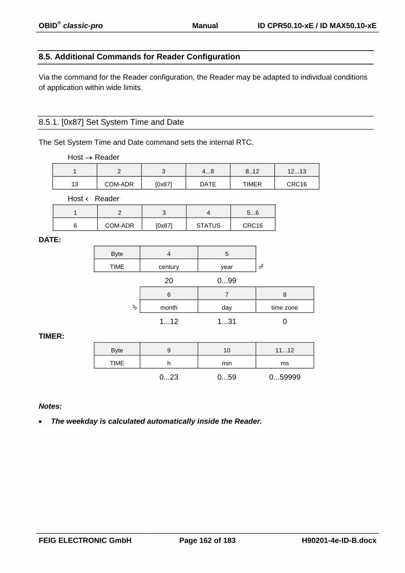
OBID® classic-pro Manual ID CPR50.10-xE / ID MAX50.10-xE
FEIG ELECTRONIC GmbH Page 162 of 183 H90201-4e-ID-B.docx
8.5. Additional Commands for Reader Configuration
Via the command for the Reader configuration, the Reader may be adapted to individual conditions
of application within wide limits.
8.5.1. [0x87] Set System Time and Date
The Set System Time and Date command sets the internal RTC.
Host Reader
1 2 3 4...8 8..12 12...13
13 COM-ADR [0x87] DATE TIMER CRC16
Host Reader
1 2 3 4 5...6
6 COM-ADR [0x87] STATUS CRC16
DATE:
Byte 4 5
TIME century year
20 0...99
6 7 8
month day time zone
1...12 1...31 0
TIMER:
Byte 9 10 11...12
TIME h min ms
0...23 0...59 0...59999
Notes:
The weekday is calculated automatically inside the Reader.
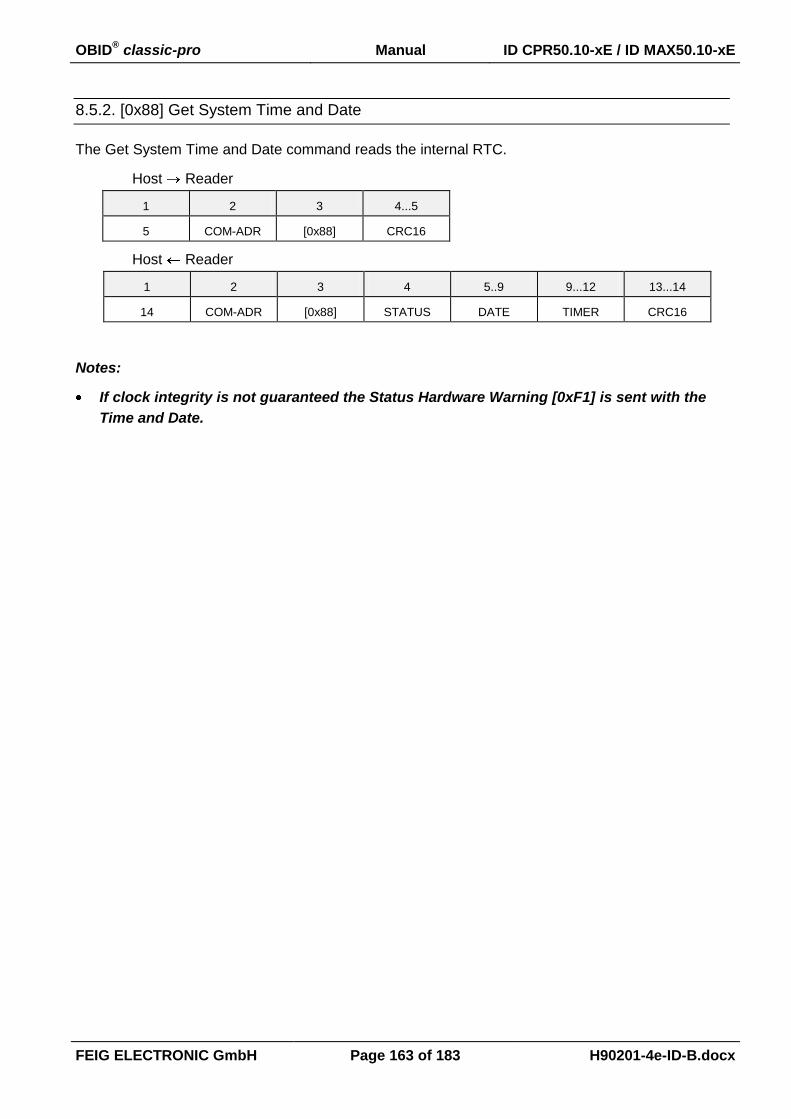
OBID® classic-pro Manual ID CPR50.10-xE / ID MAX50.10-xE
FEIG ELECTRONIC GmbH Page 163 of 183 H90201-4e-ID-B.docx
8.5.2. [0x88] Get System Time and Date
The Get System Time and Date command reads the internal RTC.
Host Reader
1 2 3 4...5
5 COM-ADR [0x88] CRC16
Host Reader
1 2 3 4 5..9 9...12 13...14
14 COM-ADR [0x88] STATUS
DATE TIMER CRC16
Notes:
If clock integrity is not guaranteed the Status Hardware Warning [0xF1] is sent with the
Time and Date.

OBID® classic-pro Manual ID CPR50.10-xE / ID MAX50.10-xE
FEIG ELECTRONIC GmbH Page 164 of 183 H90201-4e-ID-B.docx
8.6. Additional Commands for Reader Control
8.6.1. [0x66] Get Reader Info Mode = 0x04 (Additional firmware functionality)
This protocol allows you to determine Additional firmware functionality.
Host Reader
1 2 3 4 5...6
6 COM-ADR [0x66] MODE CRC16
Host Reader
1 2 3 4 5 6
17 COM-ADR [0x66] STATUS1 TEMPLATE FNC_LST0
7...8 8...10 1...12 13...14 15 16...17
- - - - - CRC16
MODE:
0x04: Additional firmware functionality.
TEMPLATE:
Indicates how to interpret the following content depending on the reader type
0x01: ID CPR-Family
FNC_LST0:
Each bit represents a firmware functionality.
Bit: 7 6 5 4 3 2 1 0
Function MAX 0 0 0 MFP MFD MAD TCL
TCL:
Indicates the support of the T=CL Function (Command [0xB2][0xBE])
b0: T=CL function is not supported
b1: T=CL function is supported
MAD:
Indicates the support of MAD (Mifare Application Directory) for Access
Control
b0: MAD is not supported
b1: MAD is supported
1 see: ANNEX C: Index of Status Bytes

OBID® classic-pro Manual ID CPR50.10-xE / ID MAX50.10-xE
FEIG ELECTRONIC GmbH Page 165 of 183 H90201-4e-ID-B.docx
MFD (Mifare DESFire high level crypto function):
Indicates the support of crypto functions with DESFire Commands
[0xC1][0x##] and [0xC3][0x##].
b0: Mifare DESFire crypto functions are not supported
b1: Mifare DESFire crypto functions are supported
MFP (Mifare PLUS high level crypto function):
Indicates the support of crypto functions with Mifare Plus Commands
[0xC2][0x##].
b0: Mifare Plus crypto functions are not supported
b1: Mifare Plus crypto functions are supported
MAX:
Indicates the support of MAX (Access Control)
b0: MAX is not supported
b1: MAX is supported

OBID® classic-pro Manual ID CPR50.10-xE / ID MAX50.10-xE
FEIG ELECTRONIC GmbH Page 166 of 183 H90201-4e-ID-B.docx
8.6.2. [0x6E] Reader Diagnostic Mode = 0x06 (MAX Status)
The command Reader Diagnostic displays several hardware diagnostics on the Reader.
Host Reader
1 2 3 4 5...6
6 COM-ADR [0x6E] MODE CRC16
Host Reader
1 2 3 4 5...n-2 n-1...n
n COM-ADR [0x6E] STATUS DATA CRC16
MODE:
0x06: MAX Status.
DATA:
Response for MAX Status (MODE = 0x06)
5..6 7..8 9..10
ERROR_FL
AGS
EVENT_TA
B_SIZE
EVENT_TA
B_LEN
ERROR_FLAGS:
Bit 15 14 13 12 11 10 9 8
Fu
nctio
n 0 0 0 0 0 0 0 0
Bit 7 6 5 4 3 2 1 0
Fu
nctio
n
UP
DA
TE
BU
SY
RE
AD
ER
CO
NF
IG 0
AC
CE
SS
HO
LID
AY
TIM
EZ
ON
E
ME
TA
DA
TA
RT
C
EVENT_TAB_SIZE
Maximum count of Event data sets in the event table
EVENT_TAB_LEN
Number of Event data sets reserved in the event table
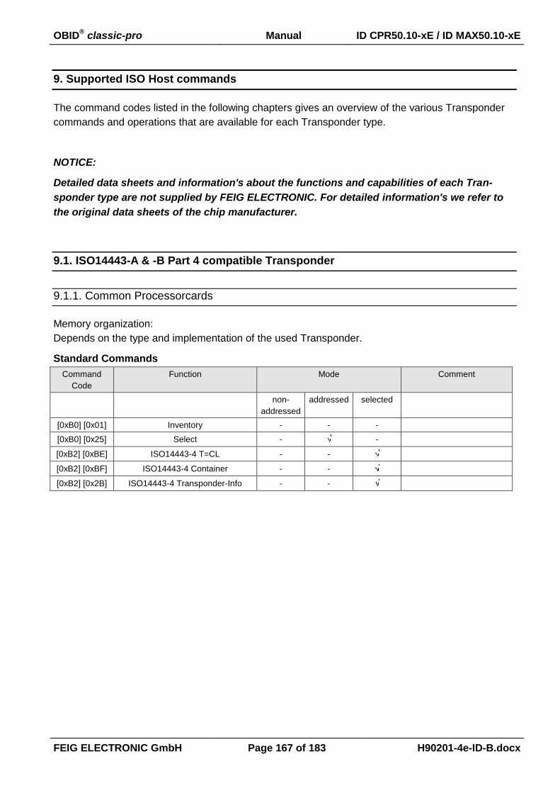
OBID® classic-pro Manual ID CPR50.10-xE / ID MAX50.10-xE
FEIG ELECTRONIC GmbH Page 167 of 183 H90201-4e-ID-B.docx
9. Supported ISO Host commands
The command codes listed in the following chapters gives an overview of the various Transponder
commands and operations that are available for each Transponder type.
NOTICE:
Detailed data sheets and information's about the functions and capabilities of each Tran-
sponder type are not supplied by FEIG ELECTRONIC. For detailed information's we refer to
the original data sheets of the chip manufacturer.
9.1. ISO14443-A & -B Part 4 compatible Transponder
9.1.1. Common Processorcards
Memory organization:
Depends on the type and implementation of the used Transponder.
Standard Commands
Command
Code
Function Mode Comment
non-
addressed
addressed selected
[0xB0] [0x01] Inventory - - -
[0xB0] [0x25] Select - -
[0xB2] [0xBE] ISO14443-4 T=CL - -
[0xB2] [0xBF] ISO14443-4 Container - -
[0xB2] [0x2B] ISO14443-4 Transponder-Info - -

OBID® classic-pro Manual ID CPR50.10-xE / ID MAX50.10-xE
FEIG ELECTRONIC GmbH Page 168 of 183 H90201-4e-ID-B.docx
9.1.2. NXP - mifare DESFire
mifare DESFire (MF3 IC D40)
mifare DESFire EV1 (2k: MF3 IC D21, 4k: MF3 IC D41, 8k: MF3 IC D81)
[0xC1] High Level Commands
Command
Code
Function Mode Comment
non-
addressed
addressed selected
[0xC1] [0xFA] DESFire Authent - -
[0xC1] [0xBD] DESFire Read Standard Data - -
[0xC1] [0x3B] DESFire Write Standard Data - -
[0xC1] [0x6C] DESFire Get Value - -
[0xC1] [0x0C] DESFire Credit - -
[0xC1] [0xDC] DESFire Debit - -
[0xC1] [0x1C] DESFire Limited Credit - -
[0xC1] [0x3B] DESFire Write Records - -
[0xC1] [0xBB] DESFire Read Records - -
[0xC1] [0xEB] DESFire Clear Record File - -
[0xC1] [0x5F] DESFire Change File Settings - -
[0xC1] [0x54] DESFire Change Key Settings - -
[0xC1] [0xC4] DESFire Change Key - -
[0xC3] High Level Commands
Command
Code
Function Mode Comment
non-
addressed
addressed selected
[0xC3] [0xFA] DESFire Authent - -
[0xC3] [0x54] DESFire Change Key Settings - -
[0xC3] [0x45] DESFire Get Key Settings - -
[0xC3] [0xC4] DESFire Change Key - -
[0xC3] [0x54] DESFire Get Key Version - -
[0xC3] [0xCA] DESFire Create Application - -
[0xC3] [0xDA] DESFire Delete Application - -
[0xC3] [0x6A] DESFire Get Application IDs - -
[0xC3] [0x6D] DESFire Get DF Names - -
[0xC3] [0x5A] DESFire Select Application - -
[0xC3] [0xFC] DESFire Format PICC - -
[0xC3] [0x60] DESFire Get Version - -
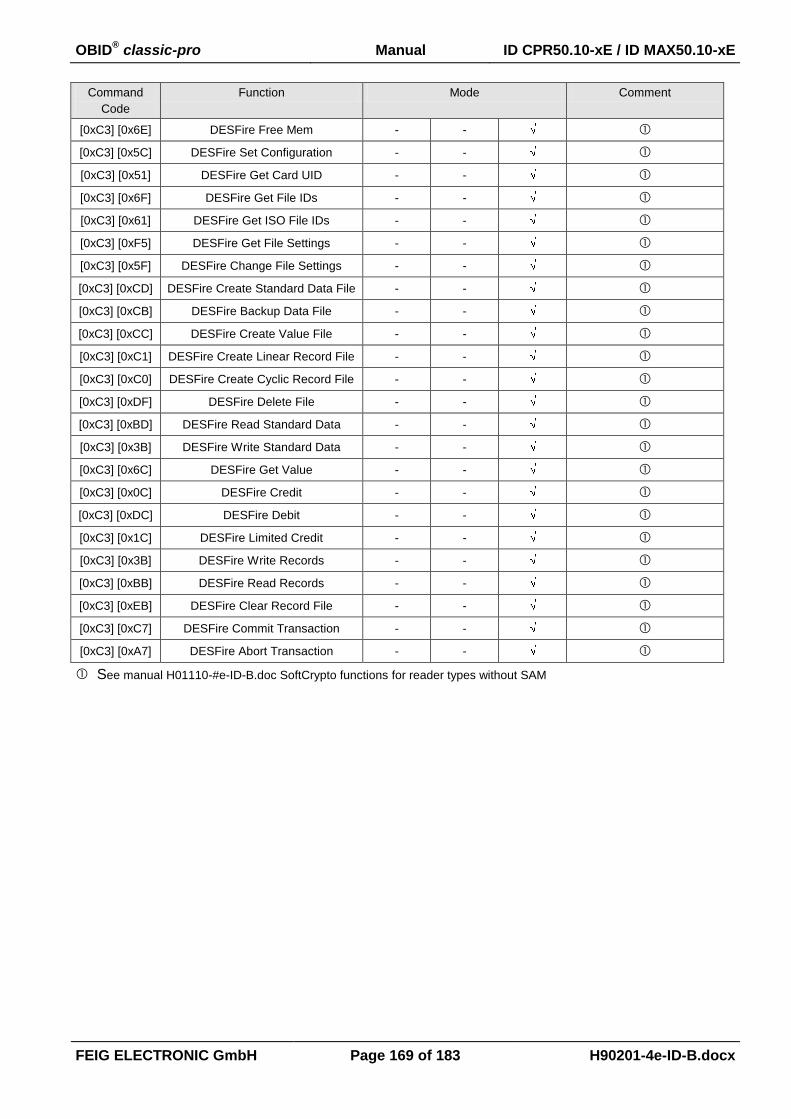
OBID® classic-pro Manual ID CPR50.10-xE / ID MAX50.10-xE
FEIG ELECTRONIC GmbH Page 169 of 183 H90201-4e-ID-B.docx
Command
Code
Function Mode Comment
[0xC3] [0x6E] DESFire Free Mem - -
[0xC3] [0x5C] DESFire Set Configuration - -
[0xC3] [0x51] DESFire Get Card UID - -
[0xC3] [0x6F] DESFire Get File IDs - -
[0xC3] [0x61] DESFire Get ISO File IDs - -
[0xC3] [0xF5] DESFire Get File Settings - -
[0xC3] [0x5F] DESFire Change File Settings - -
[0xC3] [0xCD] DESFire Create Standard Data File - -
[0xC3] [0xCB] DESFire Backup Data File - -
[0xC3] [0xCC] DESFire Create Value File - -
[0xC3] [0xC1] DESFire Create Linear Record File - -
[0xC3] [0xC0] DESFire Create Cyclic Record File - -
[0xC3] [0xDF] DESFire Delete File - -
[0xC3] [0xBD] DESFire Read Standard Data - -
[0xC3] [0x3B] DESFire Write Standard Data - -
[0xC3] [0x6C] DESFire Get Value - -
[0xC3] [0x0C] DESFire Credit - -
[0xC3] [0xDC] DESFire Debit - -
[0xC3] [0x1C] DESFire Limited Credit - -
[0xC3] [0x3B] DESFire Write Records - -
[0xC3] [0xBB] DESFire Read Records - -
[0xC3] [0xEB] DESFire Clear Record File - -
[0xC3] [0xC7] DESFire Commit Transaction - -
[0xC3] [0xA7] DESFire Abort Transaction - -
See manual H01110-#e-ID-B.doc SoftCrypto functions for reader types without SAM
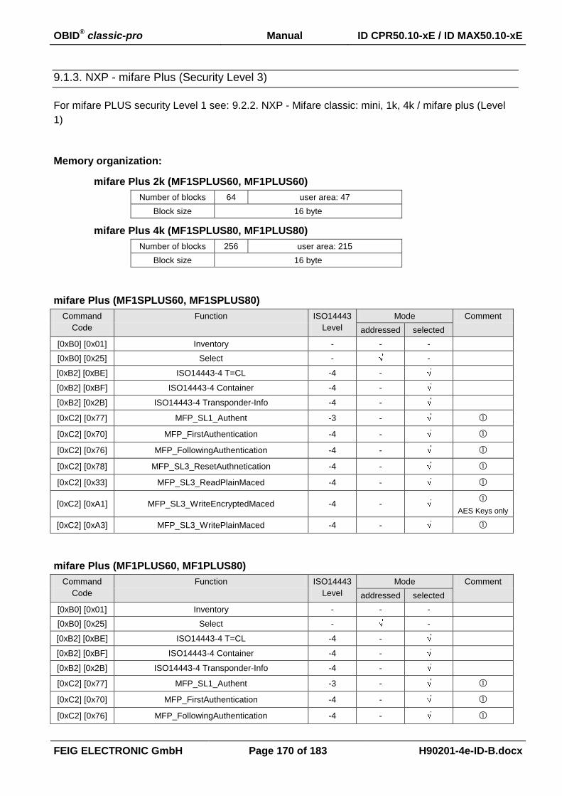
OBID® classic-pro Manual ID CPR50.10-xE / ID MAX50.10-xE
FEIG ELECTRONIC GmbH Page 170 of 183 H90201-4e-ID-B.docx
9.1.3. NXP - mifare Plus (Security Level 3)
For mifare PLUS security Level 1 see: 9.2.2. NXP - Mifare classic: mini, 1k, 4k / mifare plus (Level
1)
Memory organization:
mifare Plus 2k (MF1SPLUS60, MF1PLUS60)
Number of blocks 64 user area: 47
Block size 16 byte
mifare Plus 4k (MF1SPLUS80, MF1PLUS80)
Number of blocks 256 user area: 215
Block size 16 byte
mifare Plus (MF1SPLUS60, MF1SPLUS80)
Command
Code
Function ISO14443
Level
Mode Comment
addressed selected
[0xB0] [0x01] Inventory - - -
[0xB0] [0x25] Select - -
[0xB2] [0xBE] ISO14443-4 T=CL -4 -
[0xB2] [0xBF] ISO14443-4 Container -4 -
[0xB2] [0x2B] ISO14443-4 Transponder-Info -4 -
[0xC2] [0x77] MFP_SL1_Authent -3 -
[0xC2] [0x70] MFP_FirstAuthentication -4 -
[0xC2] [0x76] MFP_FollowingAuthentication -4 -
[0xC2] [0x78] MFP_SL3_ResetAuthnetication -4 -
[0xC2] [0x33] MFP_SL3_ReadPlainMaced -4 -
[0xC2] [0xA1] MFP_SL3_WriteEncryptedMaced -4 -
AES Keys only
[0xC2] [0xA3] MFP_SL3_WritePlainMaced -4 -
mifare Plus (MF1PLUS60, MF1PLUS80)
Command
Code
Function ISO14443
Level
Mode Comment
addressed selected
[0xB0] [0x01] Inventory - - -
[0xB0] [0x25] Select - -
[0xB2] [0xBE] ISO14443-4 T=CL -4 -
[0xB2] [0xBF] ISO14443-4 Container -4 -
[0xB2] [0x2B] ISO14443-4 Transponder-Info -4 -
[0xC2] [0x77] MFP_SL1_Authent -3 -
[0xC2] [0x70] MFP_FirstAuthentication -4 -
[0xC2] [0x76] MFP_FollowingAuthentication -4 -
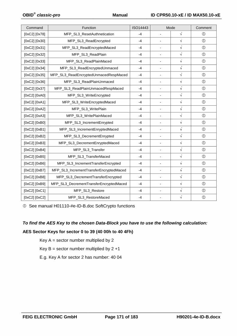
OBID® classic-pro Manual ID CPR50.10-xE / ID MAX50.10-xE
FEIG ELECTRONIC GmbH Page 171 of 183 H90201-4e-ID-B.docx
Command
Code
Function ISO14443
Level
Mode Comment
[0xC2] [0x78] MFP_SL3_ResetAuthnetication -4 -
[0xC2] [0x30] MFP_SL3_ReadEncrypted -4 -
[0xC2] [0x31] MFP_SL3_ReadEncryptedMaced -4 -
[0xC2] [0x32] MFP_SL3_ReadPlain -4 -
[0xC2] [0x33] MFP_SL3_ReadPlainMaced -4 -
[0xC2] [0x34] MFP_SL3_ReadEncryptedUnmaced -4 -
[0xC2] [0x35] MFP_SL3_ReadEncryptedUnmacedRespMaced -4 -
[0xC2] [0x36] MFP_SL3_ReadPlainUnmaced -4 -
[0xC2] [0x37] MFP_SL3_ReadPlainUnmacedRespMaced -4 -
[0xC2] [0xA0] MFP_SL3_WriteEncrypted -4 -
[0xC2] [0xA1] MFP_SL3_WriteEncryptedMaced -4 -
[0xC2] [0xA2] MFP_SL3_WritePlain -4 -
[0xC2] [0xA3] MFP_SL3_WritePlainMaced -4 -
[0xC2] [0xB0] MFP_SL3_IncrementEnrypted -4 -
[0xC2] [0xB1] MFP_SL3_IncrementEnryptedMaced -4 -
[0xC2] [0xB2] MFP_SL3_DecrementEnrypted -4 -
[0xC2] [0xB3] MFP_SL3_DecrementEnryptedMaced -4 -
[0xC2] [0xB4] MFP_SL3_Transfer -4 -
[0xC2] [0xB5] MFP_SL3_TransferMaced -4 -
[0xC2] [0xB6] MFP_SL3_IncrementTransferEncrypted -4 -
[0xC2] [0xB7] MFP_SL3_IncrementTransferEncryptedMaced -4 -
[0xC2] [0xB8] MFP_SL3_DecrementTransferEncrypted -4 -
[0xC2] [0xB9] MFP_SL3_DecrementTransferEncryptedMaced -4 -
[0xC2] [0xC1] MFP_SL3_Restore -4 -
[0xC2] [0xC2] MFP_SL3_RestoreMaced -4 -
See manual H01110-#e-ID-B.doc SoftCrypto functions
To find the AES Key to the chosen Data-Block you have to use the following calculation:
AES Sector Keys for sector 0 to 39 (40 00h to 40 4Fh)
Key A = sector number multiplied by 2
Key B = sector number multiplied by 2 +1
E.g. Key A for sector 2 has number: 40 04

OBID® classic-pro Manual ID CPR50.10-xE / ID MAX50.10-xE
FEIG ELECTRONIC GmbH Page 172 of 183 H90201-4e-ID-B.docx
9.2. ISO14443-A Part 3 compatible Transponder
9.2.1. Infineon - my-d move SLE66R01P
Memory organization (SLE66R01P): 38 x 4 byte = 152 byte
Number of blocks 38 user area: 12 ... 32
Block size 4 byte
Command
Code
Function Mode Comment
non-
addressed
addressed selected
[0xB0] [0x01] Inventory - - -
[0xB0] [0x23] Read Multiple Blocks - - Security Status is always
0x00
[0xB0] [0x24] Write Multiple Blocks - -
[0xB0] [0x25] Select - -
[0xB0] [0xC0] Halt - -
Commands for password protected memory and multiple block read/write commands can be
carried out by using [0xBD] ISO14443A Transparent Command or by with using the OBID®
C++ Class Library ID FEDM up from version 3.01.00 (see document H10202-##-ID-B) of OBID®
software development kit.
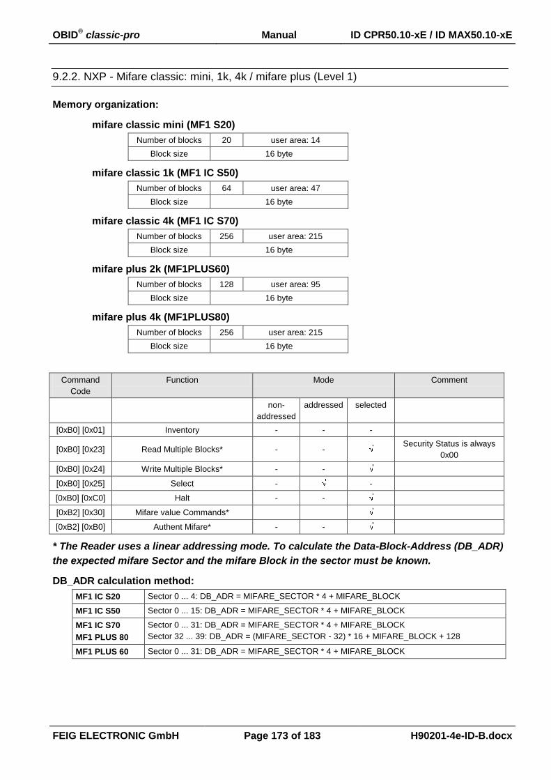
OBID® classic-pro Manual ID CPR50.10-xE / ID MAX50.10-xE
FEIG ELECTRONIC GmbH Page 173 of 183 H90201-4e-ID-B.docx
9.2.2. NXP - Mifare classic: mini, 1k, 4k / mifare plus (Level 1)
Memory organization:
mifare classic mini (MF1 S20)
Number of blocks 20 user area: 14
Block size 16 byte
mifare classic 1k (MF1 IC S50)
Number of blocks 64 user area: 47
Block size 16 byte
mifare classic 4k (MF1 IC S70)
Number of blocks 256 user area: 215
Block size 16 byte
mifare plus 2k (MF1PLUS60)
Number of blocks 128 user area: 95
Block size 16 byte
mifare plus 4k (MF1PLUS80)
Number of blocks 256 user area: 215
Block size 16 byte
Command
Code
Function Mode Comment
non-
addressed
addressed selected
[0xB0] [0x01] Inventory - - -
[0xB0] [0x23] Read Multiple Blocks* - - Security Status is always
0x00
[0xB0] [0x24] Write Multiple Blocks* - -
[0xB0] [0x25] Select - -
[0xB0] [0xC0] Halt - -
[0xB2] [0x30] Mifare value Commands*
[0xB2] [0xB0] Authent Mifare* - -
* The Reader uses a linear addressing mode. To calculate the Data-Block-Address (DB_ADR)
the expected mifare Sector and the mifare Block in the sector must be known.
DB_ADR calculation method:
MF1 IC S20 Sector 0 ... 4: DB_ADR = MIFARE_SECTOR * 4 + MIFARE_BLOCK
MF1 IC S50 Sector 0 ... 15: DB_ADR = MIFARE_SECTOR * 4 + MIFARE_BLOCK
MF1 IC S70
MF1 PLUS 80
Sector 0 ... 31: DB_ADR = MIFARE_SECTOR * 4 + MIFARE_BLOCK
Sector 32 ... 39: DB_ADR = (MIFARE_SECTOR - 32) * 16 + MIFARE_BLOCK + 128
MF1 PLUS 60 Sector 0 ... 31: DB_ADR = MIFARE_SECTOR * 4 + MIFARE_BLOCK

OBID® classic-pro Manual ID CPR50.10-xE / ID MAX50.10-xE
FEIG ELECTRONIC GmbH Page 174 of 183 H90201-4e-ID-B.docx
9.2.3. NXP - Mifare Ultralight
Memory organization (MF0U10 / MF0U11): 16 x 4 byte = 64 byte
Number of blocks 16 user area: 4...15; (2...3)
Block size 4 byte
Command
Code
Function Mode Comment
non-
addressed
addressed selected
[0xB0] [0x01] Inventory - - -
[0xB0] [0x23] Read Multiple Blocks - - Security Status is always
0x00
[0xB0] [0x24] Write Multiple Blocks - -
[0xB0] [0x25] Select - -
[0xB0] [0xC0] Halt - -
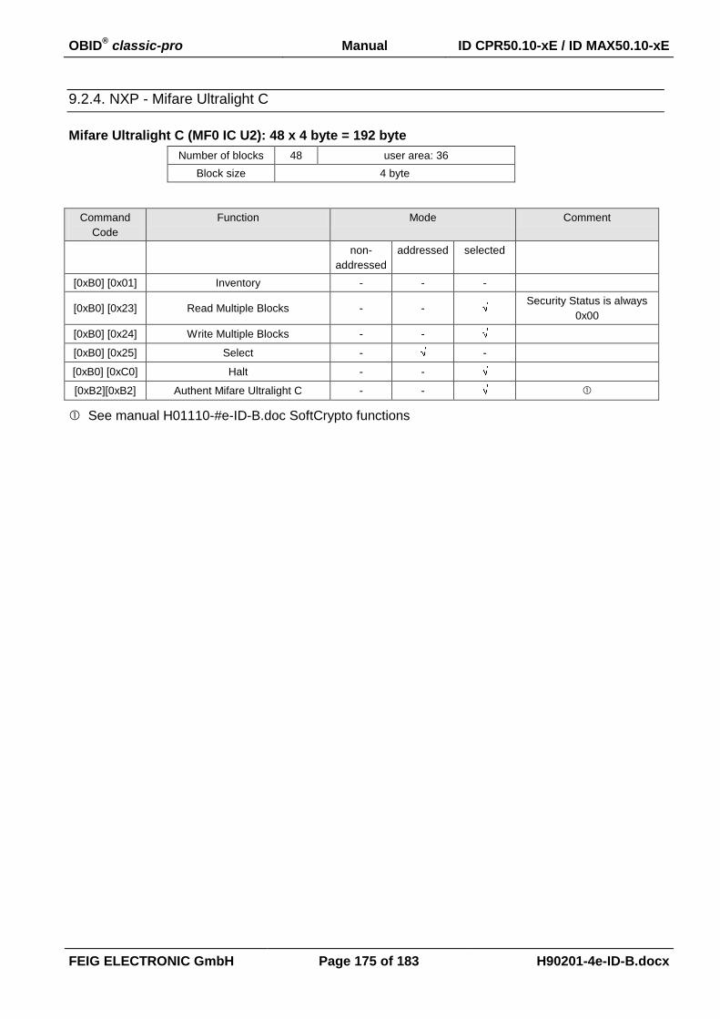
OBID® classic-pro Manual ID CPR50.10-xE / ID MAX50.10-xE
FEIG ELECTRONIC GmbH Page 175 of 183 H90201-4e-ID-B.docx
9.2.4. NXP - Mifare Ultralight C
Mifare Ultralight C (MF0 IC U2): 48 x 4 byte = 192 byte
Number of blocks 48 user area: 36
Block size 4 byte
Command
Code
Function Mode Comment
non-
addressed
addressed selected
[0xB0] [0x01] Inventory - - -
[0xB0] [0x23] Read Multiple Blocks - - Security Status is always
0x00
[0xB0] [0x24] Write Multiple Blocks - -
[0xB0] [0x25] Select - -
[0xB0] [0xC0] Halt - -
[0xB2][0xB2] Authent Mifare Ultralight C - -
See manual H01110-#e-ID-B.doc SoftCrypto functions
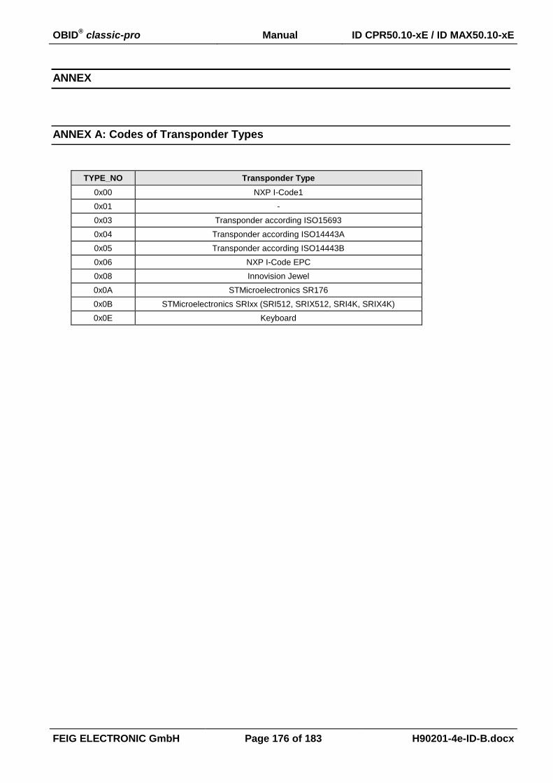
OBID® classic-pro Manual ID CPR50.10-xE / ID MAX50.10-xE
FEIG ELECTRONIC GmbH Page 176 of 183 H90201-4e-ID-B.docx
ANNEX
ANNEX A: Codes of Transponder Types
TYPE_NO Transponder Type
0x00 NXP I-Code1
0x01 -
0x03 Transponder according ISO15693
0x04 Transponder according ISO14443A
0x05 Transponder according ISO14443B
0x06 NXP I-Code EPC
0x08 Innovision Jewel
0x0A STMicroelectronics SR176
0x0B STMicroelectronics SRIxx (SRI512, SRIX512, SRI4K, SRIX4K)
0x0E Keyboard

OBID® classic-pro Manual ID CPR50.10-xE / ID MAX50.10-xE
FEIG ELECTRONIC GmbH Page 177 of 183 H90201-4e-ID-B.docx
ANNEX B: Codes of Reader Types
No. Reader Type
80 ID CPR.M02
81 ID CPR.02
82* ID CPR40.xx-U with USB interface
83* ID CPR40.xx- with asynchronous (RS232) interface
84 ID CPR50.xx
85 ID CPR44.xx
86 ID CPR30.xx
87 ID CPR52.xx
88 ID CPR.04-USB (USB-Version; 596/#)
100 ID MAX50.xx
* if a reader is equipped with both interfaces the reader type is switched dynamical depending on the
currently used interface.

OBID® classic-pro Manual ID CPR50.10-xE / ID MAX50.10-xE
FEIG ELECTRONIC GmbH Page 178 of 183 H90201-4e-ID-B.docx
ANNEX C: Index of Status Bytes
Hex-value General
0x00 OK:
Data / parameters have been read or stored without error
Control command has been executed
Hex-value Transponder Status
0x01 No Transponder:
No Transponder is located within the detection range of the Reader.
The Transponder in the detection range has been switched to mute.
The communication between Reader and Transponder has been interfered and the Reader is not able to read the Transponder anymore.
0x02 Data False:
CRC, parity or framing error at received data.
0x03 Write-Error: Negative plausibility check of the written data:
Attempt to write on a read-only storing-area.
Too much distance between Transponder and Reader antenna.
Attempt to write in a noise area.
0x04 Address-Error: The required data are outside of the logical or physical Transponder-address area:
The address is beyond the max. address space of the Transponder.
The address is beyond the configured address space of the Transponder.
0x05 Wrong Transponder-Type: This command is not applicable at the Transponder:
Attempt to write on or read from a Transponder.
A special command is not applicable to the Transponder.
0x08 Authent-Error The reader could not identify itself to the transponder as authorized:
reader- and transponder Keys do not correspond
0x0E General-Error
The Transponder answered with an undefined or general error code
0x83 RF Communication Error:
Anticollision could not be finished by the reader.
Corrupted or faulty data exchange between reader and Transponder
0x92 No valid Data:
There is no valid data in the buffer.
There is no Transponder in the antenna field.
0x93 Data Buffer Overflow:
A data buffer overflow occurred.
0x94 More Data:
There are more Transponder data sets requested than the response protocol can transfer at once.
0x95 ISO15693-Error:
An additional error code for ISO15693 Transponders is sent with response data. (see: ANNEX C1:
ISO15693-Error, Error-Codes)
0x96 ISO14443-Error:
An additional error code for ISO14443 Transponders is sent with response data. (see: ANNEX C2:
ISO14443-Error, Error-Codes)
0x97 Crypto Processing Error
An additional code for source and reason of the error is sent with response data (See: ANNEX C3:
Crypto Processing Error - ERROR-CODE)

OBID® classic-pro Manual ID CPR50.10-xE / ID MAX50.10-xE
FEIG ELECTRONIC GmbH Page 179 of 183 H90201-4e-ID-B.docx
Hex-value Parameter Status
0x10 EEPROM-failure:
The EEPROM of the Reader is not able to be written on.
Before writing onto the EEPROM a faulty checksum of parameters has been detected.
0x11 Parameter-Range-Error:
The value range of the parameters was exceeded.
Hex-value Interface Status
0x80 Unknown Command:
The Reader does not support the selected function.
0x81 Length-Error:
The received protocol contains not the expected content.
0x82 Command (currently) not available:
The reader is configured in scan-mode and had received an ISO Host-mode command.
0x12 Reader authent error:
The host could not identify itself to the reader as authorized. -> False authentkey
0x19 Cryptoproccesing error:
The reader is configured in cryptomode and ignores plain commands
Hex-value Reader Status
0xF1 Hardware Warning:
The Firmware is incompatible with the hardware.
0xF3 MAX TableUpdate Error:
The Table Data for ID MAX50.10xE was not correct.
Hex-value SAM Status
0x31 No SAM detected
The reader get no response from the Smart Card
0x32 Requested SAM is not activated
The requested SAM is not activated by the SAM Activate command
0x33 Requested SAM is already activated
0x34 Requested protocol is not supported by the SAM
Check if T=0 or T=1 protocol is supported by the SAM
0x35 SAM communication error
A data transmission error occurred while communication with the SAM
0x36 Timeout
The Reader got no response from SAM within the defined timeout
0x37 Unsupported SAM Baudrate
The used parameter of Fi and/or Di are not supported by the reader

OBID® classic-pro Manual ID CPR50.10-xE / ID MAX50.10-xE
FEIG ELECTRONIC GmbH Page 180 of 183 H90201-4e-ID-B.docx
ANNEX C1: ISO15693-Error, Error-Codes
Hex-value Response error code definition
0x01 The command is not supported, i.e. the request code is not recognised
0x02 The command is not recognised, for example: a format error occured
0x03 The option is not supported
0x0F Unknown error
0x10 The specified block is not available (doesn’t exist)
0x11 The specified block is already locked and thus cannot be locked again
0x12 The specified block is locked and ist content cannot be changed
0x13 The specified block was not successfully programmed
0x14 The specified block was not successfully locked
0xA0 - 0xDF Custom command error codes
all others reserved for future use
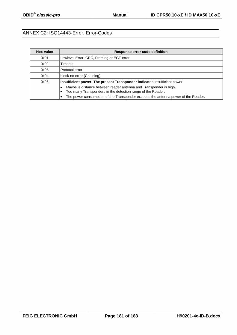
OBID® classic-pro Manual ID CPR50.10-xE / ID MAX50.10-xE
FEIG ELECTRONIC GmbH Page 181 of 183 H90201-4e-ID-B.docx
ANNEX C2: ISO14443-Error, Error-Codes
Hex-value Response error code definition
0x01 Lowlevel Error: CRC, Framing or EGT error
0x02 Timeout
0x03 Protocol error
0x04 block-no error (Chaining)
0x05 Insufficient power: The present Transponder indicates insufficient power
Maybe is distance between reader antenna and Transponder is high.
Too many Transponders in the detection range of the Reader.
The power consumption of the Transponder exceeds the antenna power of the Reader.

OBID® classic-pro Manual ID CPR50.10-xE / ID MAX50.10-xE
FEIG ELECTRONIC GmbH Page 182 of 183 H90201-4e-ID-B.docx
ANNEX C3: Crypto Processing Error - ERROR-CODE
ERROR-SOURCE = 1:
ERROR-
CODE
Status
0x96xx ISO14443-Error: An additional error code for ISO14443 Transponders is sent with response data. (ANNEX C2: ISO14433-Error, Error-Codes)
0x6581 Buffer Overflow, because the received data volume exceeds the reader internal buffer size
0x00## MFP Error The ERROR-CODE was received form the mifare Plus Card (see NXP mifare Plus functional speci-fication)
0x00## DESFire Error The ERROR-CODE was received form the DESFire Card (see NXP mifare DESFire functional spec-ification)
ERROR-SOURCE = 3:
ERROR-
CODE
Status
0x901E an error occurs while authentication, MAC calculation or CRC calculation. The reason can be a not satisfied security status or any kind of transmission errors.
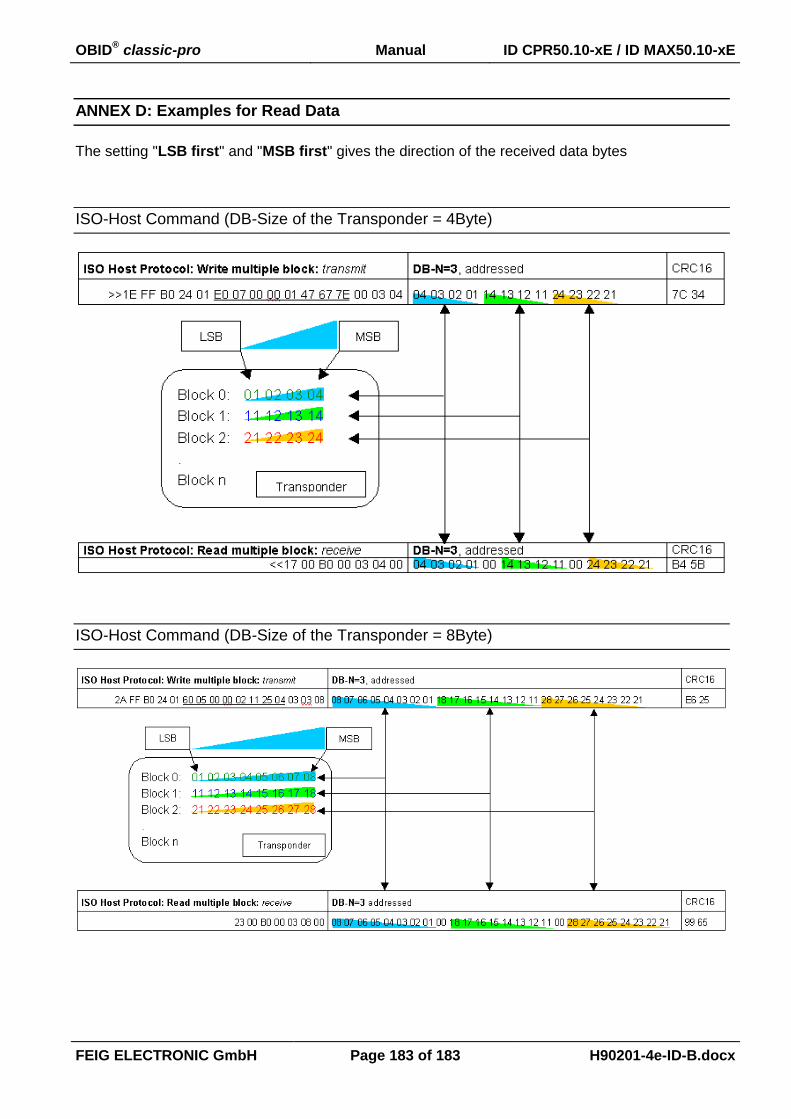
OBID® classic-pro Manual ID CPR50.10-xE / ID MAX50.10-xE
FEIG ELECTRONIC GmbH Page 183 of 183 H90201-4e-ID-B.docx
ANNEX D: Examples for Read Data
The setting "LSB first" and "MSB first" gives the direction of the received data bytes
ISO-Host Command (DB-Size of the Transponder = 4Byte)
ISO-Host Command (DB-Size of the Transponder = 8Byte)