system level design of software-defined radio … · system level design of software-defined radio...
TRANSCRIPT

System Level Design of
Software-Defined Radio
Platform
A Major Qualifying Project Report Submitted to the Faculty of
WORCESTER POLYTECHNIC INSTITUTE
In partial fulfillment of the requirements for the Degree of Bachelor of
Science in Electrical and Computer Engineering by
_____________________
Stefan Gvozdenovic
Project Advisor:
________________________
Professor Alexander Wyglinski
This report represents the work of WPI undergraduate students submitted to the faculty as evidence of
completion of a degree requirement. WPI routinely publishes these reports on its website without
editorial or peer review. For more information about the projects program at WPI, please
see http://www.wpi.edu/academics/ugradstudies/project-learning.html

2
Abstract This major qualifying project proposes a new single-board design for a Dedicated
Short Range Communication (DSRC) On Board Unit (OBU) which consists of a Zynq 7030
system on a chip and AD9361 wideband transceiver. This software-defined radio (SDR)
platform design is based on ZedBoard and FMcomms2. The advantages of this approach
compared to the ZedBoard and FMcomms2 joint solution are smaller form factor, front end
tuned to 5.9GHz and a more powerful processor. Since the prototype has not been
manufactured due to the time constraints of this project, the working implementation of 6GHz
DSRC radio 802.11p in GNU Radio has been confirmed on the lower capability hardware
USRP2 and USRP N210 (Universal Software Radio Peripheral).

3
Executive Summary
The aim of this project was to build a Software-Defined Radio (SDR) Platform capable
of being used as an OBU (On board Unit) in the automotive industry specifically for Dedicated
Short Range Communication (DSRC). Since the DSRC protocol stack varies between US,
Europe and Japan and is very complex, this project aims to show the capability of the
proposed hardware platform to run the physical layer of the DSRC (802.11p), which is the
amendment to the 802.11 standards, popularly known as Wi-Fi. The main difference that
802.11p brings are: narrower channel bandwidth of 10MHz instead of 20MHz, and a carrier
frequency of 5.9GHz.
The first half of the project timeline was spent on designing the SDR platform in “Orcad
Capture”. The proposed design runs on the Zynq 7000 system-on-a-chip, which has a
heterogeneous processor consisting of a double ARM core and programmable logic. The
radio front end is contained within a single agile transceiver AD9361. The RF performance of
this platform fully supports the 802.11p physical layer. Frequency range spans from 70MHz
up to 6GHz and the maximum bandwidth is 56MHz.
The necessary peripherals for this system were three types of memory: RAM (main
memory for the processor), flash memory (possible boot source), SD Card (recommended
boot source). Communication interfaces include gigabit Ethernet and USB 2.0. With the
Ethernet port, the proposed device could be used in the same manner as an N210, which is
in “network mode”. Network mode means that the radio application (e.g., MATLAB or GNU
Radio) runs on the host computer and not on the board itself. In this case, the Ethernet is just
used to stream IQ sample data to and from the device, which acts only as a radio front end
and does no baseband computation. Debugging communication interfaces are serial terminal

4
(USB-to-Serial) and JTAG (Joint Test Action Group). When a Zynq boots, serial terminal will
go through uBoot, FSBL (First stage boot loader) and finally boot the Linux. In case of any
failure on boot (e.g., initialization of peripherals) the serial terminal log will contain more
information. Zynq serial console has following parameters:
baud rate = 115200 data bits = 8 stop bits = 1 flow control = none parity = none
On the host computer popular serial terminal emulators are “Putty” (Windows and Linux) and
“Screen” (Linux). Except for the serial port parameters, one needs to know the virtual serial
port number assigned to the USB-to-Serial chip on board (this chip is necessary to translate
between UART/serial and USB). In Windows, so called COMx port number is found in the
device manager while on Linux, the ttyUSBx (x is the actual number) number is found by
running “dmesg | tail” after connecting the board/platform and the host with USB cable. JTAG
interface requires more than a USB cable, it needs “JTAG USB Cable” made by Digilent that
contains the Xilinx proprietary JTAG emulation software. One side of the cable plugs in to the
standard 6-pin JTAG programming header on the board and the other side is a USB that
connects to the host. The complete schematic for the board (platform and board are used
interchangeably through the document) design is in the Appendix A.
In order to meet the project objectives, it can be argued that the proposed platform
has more processing power than the most serious competitor E310 made by Ettus Research
(NI). Secondly, since the proposed platform’s intended application is primarily an OBU device
(secondary application is a Wi-Fi and DSRC testing equipment), the RF section contains
baluns that are essentially matching six of the receive channels to the following frequencies:
5.9GHz band, 2.4GHz band and 2Mhz-2.1GHz low frequency band.

5
Project Objectives:
Communication system capable of transmitting/receiving 10 MHz of bandwidth
Form factor of approximately 30x51x5mm
Power consumption of about 4W
The AD9361 has 2 receive and 2 transmit chains. Each of the transmit chains is broken out
to two separate channels and each receive chain is broken out to the three channels.
Figure 1 - Experiment Setup with N210 (left) and USRP2 (right). The only relevant difference between N210 and USRP2 is that FPGA image and ZPU firmware is loaded from SD card in case of USRP2 or from flash IC in case of N210. The box at the bottom is a spectrum analyzer used to confirm the presence of 802.11p carrier frequency.
Due to time constraints of the project and limited budget, instead of fabricating the new
design, the similar SDR platform was used to confirm the hardware capability to run 802.11p.
Specifically, the N210 and USRP2 (Universal Software Radio Peripheral) were used to show
the 802.11p implementation in GNU Radio (Figure 1). Both N210 and USRP2 have the same
daughter-boards and therefore the same RF performance. The code and the GNU Radio flow

6
graph were adopted from the open-source GitHub repository by Bastian Bloessl [2]. Other
SDR platforms, mainly Zedboard+FMCOMMS2 and E310, were tried before using N210 for
the final implementation. N210 was the most supported and documented platform which
allowed easier troubleshooting and debugging.
The contribution of this project is the design of the Software-defined radio (SDR)
platform on one hand. On the other hand, it has been confirmed that the N210, similar platform
to the proposed one, can transmit/receive 802.11p packets. Board design is described in the
“Proposed System” section and the schematic is included in the appendix A. Implementation
of 802.11p in GNU Radio is explained in the “Results and testing” section.

7
Table of Contents Abstract ......................................................................................................................................................... 2
Executive Summary ....................................................................................................................................... 3
Table of Figures ............................................................................................................................................. 9
Acknowledgements ..................................................................................................................................... 11
1. Introduction ........................................................................................................................................ 12
1.1 Motivation ................................................................................................................................... 13
1.2 Marketing Plan ............................................................................................................................ 14
2. Current State of the Art ...................................................................................................................... 16
2.1 Problem Statement ..................................................................................................................... 18
Run software radio suite on board ............................................................................................. 18
Design prototype architecture that fits small form factor .......................................................... 18
Low power ................................................................................................................................... 19
2.2 Proposed Contributions .............................................................................................................. 19
Communication system capable of transmitting/receiving at least 10 MHz of bandwidth ....... 19
Form factor of approximately 30x51x5mm ................................................................................ 20
Power consumption of about 4W ............................................................................................... 20
2.3 Organization of the Report ......................................................................................................... 20
3. Background Information ..................................................................................................................... 22
3.1 DSRC versus Wi-Fi ....................................................................................................................... 23
3.2 GNU Radio ................................................................................................................................... 25
3.3 FPGA Developing Environments ................................................................................................. 26
3.4 Linux on a Custom Hardware ...................................................................................................... 28
Chapter Summary ................................................................................................................................... 30
4. Proposed System ................................................................................................................................ 31
Chapter Summary ................................................................................................................................... 42
5. Implementation .................................................................................................................................. 43
5.1 Zedboard ..................................................................................................................................... 43
5.2 E310 ............................................................................................................................................ 49
5.3 N210 ............................................................................................................................................ 50
Chapter Summary ................................................................................................................................... 51
6. Results and Testing ............................................................................................................................. 52
Chapter Summary ................................................................................................................................... 61

8
7. Conclusion ........................................................................................................................................... 62
Future Work ............................................................................................................................................ 62
8. References .......................................................................................................................................... 66
9. Appendix A .......................................................................................................................................... 70

9
Table of Figures Figure 1 - Experiment Setup with N210 (left) and USRP2 (right). The only relevant difference between
N210 and USRP2 is that FPGA image and ZPU firmware is loaded from SD card in case of USRP2 or from
flash IC in case of N210. The box at the bottom is a spectrum analyzer used to confirm the presence of
802.11p carrier frequency. ........................................................................................................................... 5
Figure 2 - Different devices in an automobile connected together with a CAN bus [28]. Proposed SDR
platform could easily connect to the existing CAN bus, making the integration simple. ........................... 12
Figure 3 - Block diagram of E310. Proposed platform looks the same except it does not include the GPS
receiver and filter bank. The main advantage of these type of platforms is that they can perform data
processing on board (on Zynq) rather than host computer [30]. ............................................................... 14
Figure 4 - Communications Equipment Manufacturing Revenue. Proposed SDR platform would fall under
Wireless networking equipment, however the SDR platform is creating a new markets potentially bigger
than the that of wireless networking equipment. ...................................................................................... 15
Figure 5 - Characteristics of different 802.11 standards. * 802.11p is half-duplex; throughput at
maximum bandwidth is 27 Mbps each direction. ** Provides the 802.11a packet format in the 4.9 GHz
band in Japan [34]. ...................................................................................................................................... 23
Figure 6 - DSRC applications by communication categories [44]. .............................................................. 25
Figure 7 – USRP N210 signal chain. LNA, PA and RF mixers are part of the XCVR2450 daughterboards.
ADCs and DACs are the integrated circuits on the main board. Up/down conversion and filtering is
implemented on the FPGA. ......................................................................................................................... 27
Figure 8 - Overview of development tools [26]. The point is that a Zynq image can be created through
Xilinx tools only or through the open source third party tools................................................................... 29
Figure 9 - Block diagram of the proposed SDR platform ............................................................................ 31
Figure 10 - Block diagram of the RF section of the proposed SDR platform (First half). First half shows
transmit chain TX1 and receive chain RX1. Each receive chain breaks out to three channels, namely
RX1A, RX1B and RX1C. Each transmit channel is broken out to two transmit channels, namely TX1A and
TX1B. ........................................................................................................................................................... 32
Figure 11 - Block diagram of the RF section of the proposed SDR platform (Second Half). Second half is
the same as first. Only difference are the naming of the signal chains, TX2 and RX2. ............................... 33
Figure 12 - Zynq 7000 All Programmable SoC. Processing System is what is shown on most of the image.
Programmable logic is the bottom block showing different interconnects. ............................................. 35
Figure 13 - MIO Table shows which pins on the physical package can use which peripherals. There are 54
pins, numbered from 0 to 53. MIO Bank 0 goes from 0 to 15 and MIO Bank 1 goes from 16 to 53. ......... 37
Figure 14 - Ethernet block diagram [39] shows the data lines between KS9031 Ethernet PHY, Ethernet
connector and the Zynq MIO bank. Corresponding Zynq pinout [9] (part of Figure 12) shows the RGMII
data lines. .................................................................................................................................................... 39
Figure 15 - JTAG connection [40] between a Zynq and the JTAG programming header from Digilent. .... 40
Figure 16 - SD card pinout [9] (part of the Figure 12). SD card has to connect to the certain pins which
Zynq defaults to use on boot from SD card. Small image shows pins used for serial console. .................. 41
Figure 17 - Zedboard+FMCOMMS2 Platform. Radio front end that is AD9361 in FMCOMMS2 is broken
down to two differential transmit and receive chains. Because the chains are differential the ADC/DAC
looks like there is two of them within one. ................................................................................................ 44
Figure 18 - Zedboard and FMCOMMS2 setup requires extra components: keyboard, mouse (connected
through USB hub to USB2.0 port), HDMI monitor and power supply for Zedboard. ................................. 45

10
Figure 19 - ZedBoard jumper map [41]. Most important jumpers: JP7-JP11 (boot select), JP18
(FMCOMMS2 voltage supply), JP2 and JP3 (Vbus 5V and USB host mode). .............................................. 46
Figure 20 – FPGA accelerated FIR filter example in GNU Radio. Four main parts are shown in red. ......... 48
Figure 21 - E310 Architecture. E310 has processing power (Zynq SoC) unlike earlier USRP generations.
Two main blocks of E310 are the Zynq processor and AD9361 radio. ...................................................... 49
Figure 22 - N210 left and E310 right. .......................................................................................................... 50
Figure 23 - Location of the Serial Output 4-pin header on the USRP N210 main board. ........................... 52
Figure 24 - uhd_find_devices, command for discovering USRP devices connected to the machine. Two
devices are discovered. Both of them are of USRP2 type, but one is actually USRP2 and the other is
N210. To make sure which one is which (determine its IP address) one would look up the serial number
on the sticker in the back of the USRP and compare it to the serial listed in this figure. .......................... 53
Figure 25 - Screenshot of the N210 “boot log” from serial console. To be technically correct, what N210
boots is not an OS but FPGA image and ZPU microcontroller firmware (ZPU is a softcore microcontroller
implemented on the FPGA).Also N210 does not really have a complete serial console, since it only
transmits “boot log” on power up and does not receive any commands .................................................. 53
Figure 26 - To find a number of the virtual serial port in Linux (ttyUSBx, the easiest way is to run dmesg |
tail, right after plugging in the USB-to-serial converter/cable. .................................................................. 54
Figure 27 - Running Transmitter. Sample rate, gain, channel and the different constellations can be
selected on the run. .................................................................................................................................... 55
Figure 28 - Running Receiver. Sample rate, gain and channel are selected on the run. Received
constellation is shown on the scope plot. .................................................................................................. 56
Figure 29 - Received string "Hello World" is shown in the GNU Radio Companion console. Console might
also indicate error conditions such as RX buffer overflows and/or TX buffer underflow. ......................... 56
Figure 30 - BPSK, QPSK, 16-QAM and 64-QAM Constellations. .................................................................. 57
Figure 31 - Rate field determines the modulation type [25] ...................................................................... 58
Figure 32 - IEEE 802.11 Receiver ................................................................................................................. 59
Figure 33 - IEEE 802.11 Transmitter ............................................................................................................ 60
Figure 34 - Spectrum Mask for 802.11p ..................................................................................................... 65
Figure 35 - Cohda Wireless Products, OBU left, RDU right ......................................................................... 65

11
Acknowledgements
Alex Ryan
Travis Collins
Dr. Radu David
Prof. Alexander Wyglinski
Prof. Donald Brown
Prof. Sergey Makarov
Robin Getz

12
1. Introduction
The purpose of this Single-Board FPGA-Based SDR project is to design an
automotive-focused, stand-alone operation software-defined radio (SDR) prototyping unit.
The unit is targeted to be installed and operated within motor vehicles, providing full
capabilities to interface with CAN data bus (Figure 2) while also providing a broadband RF
prototyping transceiver. Proposed platform can be easily connected to the automobile’s CAN
bus through CAN-to-USB cable. Future redesign might utilize a CAN controller in the Zynq
itself.
Figure 2 - Different devices in an automobile connected together with a CAN bus [28]. Proposed SDR platform could easily connect to the existing CAN bus, making the integration simple.

13
One focused design goal for the project is to provide the ability to work with 802.11p
wireless access networks within vehicular environments (i.e. WAVE support) and be able to
implement a dedicated short-range communications (DSRC) transceiver between a car and
a monitoring ground station. One of the elements of this project that would enable us to
achieve these goals is to use the Analog Devices, Inc. AD9361 RF Agile Transceiver [29], a
fully-integrated multiple input, multiple output- (MIMO) capable RF front-end integrated circuit
(IC). Additionally, a Xilinx, Inc. Zynq 7000 system-on-chip (SoC) processor [9] was utilized,
which contains an interface to digital signal processing (DSP) capabilities.
1.1 Motivation
The issue with most of the SDR platforms on the market (e.g. USRP N210 Ettus,
HackRF, BladeRF etc.) is the throughput bottleneck and the latency in transferring data
between the front end and the processor (USB2.0, USB3.0 or gigabit Ethernet). To this day,
the best solution for this issue is USRP E310 from Ettus (National Instruments) released in
2014 (Figure 3). E310 uses a Zynq 7020, which has a double ARM core processors running
up to 1GHz and FPGA on the same chip. With such processing power and high-bandwidth
connectivity between processing system (PS or the processor) and the programmable logic
(PL or the FPGA), one can eliminate the latency between the processor and the radio front
end. The programming workflow of a Zynq platform includes programming the processor (in
C for instance) as well as the FPGA (in Verilog for example). In most available platforms, the
FPGA is only used to pass through the data (up sampling/interpolation or down
sampling/decimation without any other useful function/algorithm).

14
Figure 3 - Block diagram of E310. Proposed platform looks the same except it does not include the GPS receiver and filter bank. The main advantage of these type of platforms is that they can perform data processing on board (on Zynq) rather than host computer [30].
Most programmers would tend to implement as much functionality as possible into the
processing system since writing in C (or other higher level language) is less tedious, less
prone to error and is easier to debug (since it is actually software not reconfigurable gates)
and not to mention that compiling and then loading the FPGA image can take a while.
1.2 Marketing Plan
Software Defined Radio (SDR) Industry is a mix of telecommunications, wireless and
mobile industries. According to 2012 NAICS (North American Industry Classification System)
definition SDR would fall under Radio and Television Broadcasting and Wireless
Communication Equipment Manufacturing Industry with a NAICS code of 334220 (Equivalent
Standard Industrial Classification (SIC) code is 3663). According to IBISWorld
Communications Equipment Manufacturing Industry in USA has $34.5 billion annual revenue
(Figure 4). However only 16.9% falls under wireless networking equipment which is $5.8

15
billion. Wireless networking equipment mainly includes cell phone base stations, cell phones,
WiFi, WiMax equipment etc. Wireless telecommunications has been steadily increasing since
2009 and is expected to increase in 2014. Revenue of the Ettus Research, a National
Instruments (NI) company since 2010, has been estimated to be $550K in 2008. For purposes
of this project it will be assumed that total market share does not exceed $1 million.
Figure 4 - Communications Equipment Manufacturing Revenue. Proposed SDR platform would fall under Wireless networking equipment, however the SDR platform is creating a new markets potentially bigger than the that of wireless networking equipment.

16
2. Current State of the Art
Two competitive products from Epiq Solutions are Sidekiq [31] and Matchstiq [31].
Sidekiq is a small form factor 30x51x5mm standard compliant MiniPCIe card. It utilizes the
Xilinx Spartan-6 FPGA and AD9361 transceiver, which enables 70MHz to 6GHz frequency
range. Its power consumption is 1.6W. Maximum power consumption of MiniPCIe card is
3.3V*1.1A = 3.6W for 3.3V rail and 1.5V*0.375A = 0.56W for 1.5V rail [10]. 50Mhz bandwidth
per channel is conditional on the AD9361 transceiver, like most of other RF specifications
listed. MiniPCIe connector supports PCI express interface, first generation 2.5Gbps [11] and
USB 2.0 with maximum 480Mbps [12]. Major deficiency for this product is its price of $5000.
Sidekiq is intended for either laptop or computer tablets integration. However, its targeted
market is not ordinary WiFi network interface cards, whose price is in the range from a few
dollars to a few tens of dollars. Epiq advertises Matchstiq as “Stand-alone in UAV (unarmed
aerial vehicle)” which suggest that their intended market is military among others. Matchstiq
has a slightly more relaxed form factor of 2.2" x 4.6" x 0.9" (5.58cm x 11.68cm x 2.28cm) [6]
since it is stand-alone and does not have to be integrated. However, its frequency range is
only 300MHz to 3.8GHz, which suggests the use of the LMS6002D from Lime Microsystems.
Power consumption is <3W. Being stand-alone means that it can do the signal processing on
board. Two different versions of Matchstiq use the following processors [31]:
Option 001: TI DM3730 @ 1 GHz (ARMv7/Cortex™ A8 + TI C64x DSP)
Option Z01: Xilinx® Zynq®-7020 @ 800 MHz (ARMv7 / Cortex™ A9 Dual Core)
Ettus Research (National Instruments since 2010) is a second major competitor. It has a
wide spectrum of products. One of the cheaper ones is the USRP (Universal software radio

17
peripheral) B210, priced at $1100. It utilizes an AD9361, hence the frequency range 70MHz
to 6GHz and MIMO (2 Tx & 2 Rx) operation. It interfaces with a computer through USB 3.0.
Real-time bandwidth of 56MHz (Mbps) should have no delays while being transferred through
SuperSpeed USB connectivity (maximum bandwidth rate of 5Gbps). However, this bandwidth
may vary with different operating systems, processors etc. Data from AD9361 gets streamed
and down converted through Xilinx Spartan 6 XC6SLX150 FPGA to the USB port. The
advantage of Ettus products is that they are open-hardware (unlike Epiq Solutions) but they
are still much higher priced compared similar platforms: BladeRF, HackRF, Agile SDR. One
of the higher performance devices is a USRP N210. It comes with a Gigabit Ethernet
interface. The purpose of the two SMA connectors at front panel is defined by the
daughterboard cards inside the USRP (bought separately). Different daughterboard cards are
made for different frequency bands. It also has Xilinx® Spartan® 3A-DSP 3400 FPGA but
instead of AD9361 transceiver it uses 100 MS/s dual ADC (ADS62P45), 400 MS/s dual DAC
(AD9777). FPGA can support 100 Msps data rate in both transmit and receive directions (full
duplex).
Finally, the biggest competitor to the proposed platform is the USRP E310 which has
almost the same specification as the proposed SDR platform. E310 runs on the Zynq 7020
and its radio front end entirely relies on the ADI’s agile transceiver AD9361. E310’s radio
frequency performance is just reflection of the AD9361, whose frequency support ranges from
70MHz to 6GHz. To select the operating frequency, filter banks are applied between the
antenna and the RX channels. Maximum bandwidth is 56MHz and both ADCs and DACs are
12bit. E310 is open-hardware, meaning that PCB design files are publicly available. There is
be more information about E310 in the implementation section of the report.

18
2.1 Problem Statement
Run software radio suite on board
For a development platform it is very important to provide free design files, which
means to be open software and open hardware. Most of the current SDR platform on
the market are compatible with GNU radio, free and open source software
development toolkit for signal processing in software defined radio. However, not all
of them can run GNU radio on board. For instance, HackRF made by “Great Scott
Gadgets” uses dual ARM M4 core LPC43XX microcontroller just for streaming the
data to the host. USRP B210 from Ettus Research (bought by NI) has GNURadio and
OpenBTS support however the product is primarily advertised for use with a host
machine. B210 was used to run LTE stack with a Core i7 computer. BladeRF made
by Nuand [9] with Cypress FX3 microcontroller could possibly run OpenBTS and
OpenLTE [10] heedlessly (no computer necessary). Although not a single product,
Zedboard + FMCOMMS2 is a platform that runs GNU radio. GNU radio was able to
run on Xilinx Zynq, Beagleboard, TI OMAP 3 and TI Keystone II [12]. Currently GNU
radio has SDK support only for Zynq machines.
Design prototype architecture that fits small form factor
Apart from targeting an educational platform for hobbyists and professionals, it has
a tendency to become an integrated device/card for mobile computing devices in
which case the size really matters. In case of integration device the design would have
to fit on miniPICe card form factor. In case of an educational development platform the
dimension specifications could be looser, but still small enough when compared to
competition. Portable handheld SDR device with a size of external hard drive would
be suitable for mobile usage.

19
Low power
Power is an important consideration for a platform that has potential to get
integrated into mobile equipment. Even for standalone platform it is desirable to be
bus powered, such as BladeRF which is powered through USB3 port (although it also
has a DC power jack). Matchstiq on the other hand, requires either external power
supply (Input Connector Lemo EGG.0B.302.CLL (locking)) or it can use internal
Lithium Polymer (Rechargeable) battery [6]. HackRF as well as USRP B210 are also
USB bus powered. In order to follow up with the competition, bus powered design
(whether USB2, USB3 or Ethernet) will impose power limitations.
2.2 Proposed Contributions
Communication system capable of transmitting/receiving at least
10 MHz of bandwidth
RF bandwidth of the design will mainly be imposed by sampling rate of the
ADC/DAC inside the AD9361. Maximum real time RF bandwidth of AD9361 is 56 Mhz
(56 MHz quadrature samples, AD9361 is fully differential). Secondary bandwidth
limitation could be due to lack of computing resources of the baseband processor. Just
as a comparison B210 is benchmarked by Ettus with 61 MHz real time bandwidth
(even though it uses 56 Mhz bandwidth AD9361). BladeRF and Matchstiq can do only
28 MHz since it uses LMS6002D transceiver. Max sampling rate of HackRF is 20 MHz.
Different wireless technologies would require different bandwidths. Bandwidth of the
stereo FM radio goes up to 53 kHz. Bluetooth 2.0 technology could provide up to 3
Mbps data rate. The bandwidth for IEEE 802.11 WiFi standard is 20 MHz (depends

20
on the standard, it can be less). Therefore, the goal is to demonstrate the
transmission/reception of at least 20 MHz signal bandwidth.
Form factor of approximately 30x51x5mm
BladeRF board has a handheld form factor of 5" by 3.5" (127mm by 89mm). Size
of HackRF One board is 120 mm x 75 mm [11]. B210 is of similar area if not even
bigger (USRPs sold as testing equipment, size not an issue). ZedBoard is 6.3 inches
long and 5.3 inches wide. Form factor of a laptop hard drive (2.7 inches wide, 0.37
inch tall, and 3.96 inches long) should be enough to beat the most of the related
products. Except Agile SDR solutions, which does not hold a big market in the US and
Matchstiq from Epiq Solutions 2.2" x 4.6" x 0.9" (5.58cm x 11.68cm x 2.28cm) [6].
Power consumption of about 4W
In case an SDR device is used with a host computer it is necessary to power the
device over whichever bus that is being used. IEEE 802.3af-2003 power over Ethernet
standard provides up to 15.4 W of DC power (minimum 44 V DC and 350 mA) [18].
Whereas USB 3.0 operating in SuperSpeed mode is specified to supply maximum six
unit loads of 150mA which is 900mA * 5V = 4.5W [12]. Due to this limitation SDR
platform should draw not more than roughly 4W. The third and most likely option is to
use an external power adapter.
2.3 Organization of the Report The rest of the report is structured in four main sections: Background information;
Proposed System; Implementation and Results and Testing. Background information

21
describes the applications of the proposed SDR platform for DSRC in automotive industry
and provides brief description of DSRC and related technologies. Proposed System section
gives overview of the main components of the SDR platform design. Implementation
describes the custom board bring up, that is how to prepare the custom made Zynq based
board to run a Linux OS. Results and testing presents the accomplishments in implementing
a 802.11p (DSRC PHY) in GNU Radio using USRP N210 and USRP2 platforms.

22
3. Background Information
Software Defined Radio (SDR) is a relatively new field of study in academia. The term
was introduced by Joseph Mitola in 1992 [32]. Jeffrey H. Reed described this technology in
his book Software Radio [1]. Recently it gained more popularity due to the availability of
several commercial hardware platforms on the market. The idea behind SDR is to be able to
implement different radio technologies (e.g., Bluetooth, FM radio, WiFi, ZigBee, WiMax, LTE)
with a single reconfigurable radio front end transceiver. Such a radio does all the
demodulation/modulation, coding/decoding, filtering and other signal processing techniques
in software and/or reconfigurable hardware platforms such as FPGA.
Such a radio front end is typically capable of processing samples directly from a fast
ADC/DAC (the sampling rate of the converter will limit the bandwidth of the radio link). Where
the digitization occurs will depend on the carrier frequency. For example, in the case of AM
or FM radio frequencies, one could almost digitize the signal right after the antenna. On the
other hand, in the case of the WiFi (2.4 or 5GHz), the ADC would typically require a mixer to
down convert the frequency and possibly a combination of LNAs and filters to condition the
signal in the intermediate steps between the antenna and the ADC/DAC. Giga sample ADCs
do exist but are prohibitively expensive. For instance, ADC12J4000 is a TI made 12bit single
4GSPS RF-sampling ADC costs $3900 per unit (Mouser) and consumes 2W of power.
Signals between ADC/DAC and the processor usually requires down/up sampling and
filtering. Since these tasks can easily be implemented in parallel, the I/Q samples between
ADC/DAC and the processor are passed through the FPGA (Field programmable gate array).

23
3.1 DSRC versus Wi-Fi
DSRC or dedicated short range communication is considered to be the key technology
for the IVC (Inter vehicular communication) systems to be developed in future. FCC (Federal
Communications Commissions) in US and ETSI (European Telecommunications Standard
Institute) in Europe allocated 75 MHz and 30 MHz respectively, in the 5.9 GHz band for use
in intelligent transportation system (ITS). DSRC technology encompasses several ISO
standards for different layer in OSI (Open systems interconnection) model: physical layer (EN
12253:2004); data link layer (EN 12795:2002); application layer (EN 12834:2002) [33]. DSRC
does have a different regional standards for Japan, Europe and USA.
Figure 5 - Characteristics of different 802.11 standards. * 802.11p is half-duplex; throughput at maximum bandwidth is 27 Mbps each direction. ** Provides the 802.11a packet format in the 4.9 GHz band in Japan [34].

24
To understand 802.11p one must first understand Wi-Fi standard that is 802.11a/b/g/n.
The comparison of different 802.11 standards is shown in Figure 5. The main two difference
that 802.11p introduces are the frequency and the frequency bandwidth. The IEEE 802.11p
uses 5.9GHz band instead of 2.4GHz (802.11b/g/n) and 5GHz (802.11a/n). Also it uses
10MHz band instead of 20MHz. Half the bandwidth or double the transmission time makes
the radio link more robust in vehicular environments (multipath fading, Doppler effect, etc.).
Longer OFDM symbols means there will be less inter-symbol-interference. And a dedicated
frequency band will ensure there is no interference with legacy Wi-Fi systems.
To this day there are several existing 802.11p implementations in GNU Radio such as
[2] and [3]. The efforts put in towards software-defined implementation of PHY and MAC
layers of 802.11p (and Wi-Fi as well) are justified because such testbeds are needed by
researchers to test different modulations, medium access technologies, in a quick and
reconfigurable way. This cannot be done with the Wi-Fi cards that come in the standard
laptops. Even if we could tune the local oscillator to 5.9GHz and change the interpolation
factor, to make the Wi-Fi card run 802.11p, the rest of the parameters are static in ASICs and
not reconfigurable.
To give a more general overview, a DSRC is a medium to short range communication
with low latency. It is being worked on by IEEE and ASTM standard groups. Main benefit of
the DSRC is saving lives in traffic. The applications mostly fall under these three categories:
Collision Avoidance/Warning and Driver Assistance
Intelligent Speed Adaptation
Automated Operation
For instance, an intelligent vehicle would warn a driver in case of a possible collision, say a
car is approaching another stationary car with high speed. A vehicle would first issue a

25
warning to the driver, in case the driver does not respond or if it is too late to respond, the
vehicle would take over the breaks and prevent the crash. For example, it has been
announced on the Intelligent Transportation System (ITS) Word Congress in 2014, that the
new Cadillac, planned to be release in two years, will have a driver assistance enabling
hands-free driving on highways. Figure 6 shows more specific DSRC applications. Some of
the companies involved with the recent DSRC developments are: Arada Systems, Cohda
Wireless, NXP Semiconductors.
Figure 6 - DSRC applications by communication categories [44].
3.2 GNU Radio
GNU radio is a digital signal processing (DSP) framework which is commonly used to
develop and test SDR applications. It is graphical programming language (similar to MATLAB
Simulink) which has commonly used signal processing blocks or SPBs (GNU radio starts one

26
thread per SPB). GNU radio uses unidirectional, noncyclic graph, commonly called flow
graph, to describe the interconnection between the SPBs. GNU radio blocks are based on
stream processing. SPBs that deliver data streams (receiver or ADC) are called “sources”
and SPBs that consume data (transmitter or DAC or up-sampler) are called “sinks”. SPBs
that are neither sinks nor sources are the most common and they take data stream in, process
it and output the processes data stream out (by convention inputs are on the left side of SPBs
and outputs are on the right). In case one needs to build custom GNU radio blocks or for any
serious work one should be familiar with C++ and python. SPBs are written in C++. Compiled
blocks are called within a python script.
3.3 FPGA Developing Environments
Third generation of USRP devices supports the RFNoC which is a RF Network-on-
Chip modular SDR development on FPGA [18]. The RFNoC is still under last stages of
development and is not yet in popular use. The code for RFNoC is hosted publicly on GitHub
and under “rfnoc-devel” as a branch of a UHD project by Ettus Research. The problem with
the previous generations was a more tedious and time-consuming workflow in developing
custom logic on the FPGA parts of the USRPs. The originally provided FPGA image (in some
cases firmware for the USRP microcontroller as well) was to be modified only when switching
the developing environments. For example, Matlab and GNU Radio would require different
sets of images (and firmware versions). Nevertheless, the FPGA image contains:
1. Offset correction 2. Up and down conversion (interpolation and decimation)
This is illustrated in the Figure 7 below. This figure is applicable to the USRP family of products.
In case of the platforms that run on AD9361 (B210 and E310) entire chain in the Figure 7 below

27
is contained within the agile radio AD9361. What goes between AD9361 and PL of the Zynq
are digitized raw baseband I/Q samples.
Figure 7 – USRP N210 signal chain. LNA, PA and RF mixers are part of the XCVR2450 daughterboards. ADCs and DACs are the integrated circuits on the main board. Up/down conversion and filtering is implemented on the FPGA.
Most users/researchers do not attempt to modify the original FPGA hardware design given
by the Ettus, and where they did “develop the radio” was in C/C++/python running on a host
machine’s processor connected to the USRP. The problem with this approach can come up
in case of computationally intensive algorithms (e.g. FFT, filtering, CRC) which are more
suitable to run in parallel manner on FPGA if possible instead of a general purpose processor.
Another problem might occur due to the latency between IQ samples between USRP front
end and the GPU. In case of USRP N210, it is a gigabit Ethernet that creates this bottleneck.
In case of USRP B200/B210 series this would be USB3. In case of E310 thought, this latency
would be negligible since the radio front end (AD9361) is connected to the FPGA part of the
Zynq 7020 (that is PL or programmable logic) and FPGA or PL is then connected to the
processor (double ARM core) or the PS (Processing System) through the AXI bus (ACP port
in Linux).

28
This is where RFNoC (which works along with GNU Radio) rewards. Another, closed
source and commercial solution is HDL coder from Matlab. HDL coder allows users to
automatically generate HDL images for USRP’s FPGA directly from Matlab script or Simulink
flow graph. However, the range of hardware devices is limited. At the time of the writing of
this report, the USRP N210 is supported but for instance E310 is not.
3.4 Linux on a Custom Hardware
To set up a Linux distribution on a custom made embedded system or computer on
module (just call it computer) many pieces must come in place. The tools used in this process
will mostly depend on the processor. In case of the proposed SDR platform, the processor is
the Zynq system on a chip XC7Z030 (Zynq 7000 family). Since Xilinx is the manufacturer of
Zynq, it is no wonder that their tools are essential in the development of this product. The
main tool/software package is the Xilinx Vivado Design Suite with SDK (Software
Development Kit).
One might ask why one needs an OS at all. Since this depends on the applications,
the typical radio application will require an OS. The Zynq can also run applications (programs
in C/C++ for instance) on a bare metal, that is with no underlying OS. For this purpose one
would use the provided SDK in an Eclipse-like environment and download the code to the
Zynq like with any other microcontroller. However, for most of the applications, the Zynq offers
too much computational power that could not be practically used without an OS.
For instance, Xilinx provides their own Xilinx Zynq Linux [35] which is based on the
open source software [36]. They also provide the related support through the Embedded
Linux forum [37]. Ettus research provides OpenEmbedded Linux pre-imaged on their E310s.

29
Analog Devices officially supports the Linaro Ubuntu Linux [38] for the purposes of using
FMCOMMS boards on Zynq platforms.
Except the mentioned Xilinx tools, PetaLinux software development kit (SDK) is has
everything to build, develop, test and deploy Linux on custom embedded systems.
Customization of Xilinx PetaLinux is available under no charge. Before custom board bringup,
one can get familiar with pre-built BSPs and reference design that PetaLinux SDK provides.
Figure 8 below shows the relation between Yocto Project/Open Embedded, PetaLinux and
the Xilinx Components. It also shows two different ways to create a bootable system, which
requires an image, which consists of: Rootfs (file system); kernel; u-boot (boatloader).
Figure 8 - Overview of development tools [26]. The point is that a Zynq image can be created through Xilinx tools only or through the open source third party tools.

30
Before jumping to PetaLinux, a hardware project or Vivado/XPS project needs to be created
first. At this stage, a hardware platform is configured. This means specifying certain
configuration that Linux hardware system cannot run without the following:
1. Triple Timer Counter
2. External memory controller with at least 32MB of memory
3. UART for serial console
4. Non-volatile memory, for instance QSPI Flash or SD/MMC (Optional)
5. Ethernet (Optional)
The following steps deal with configuring Linux BSP (Board Support Package) for a specific
platform, configuring Zynq FSBL (First stage bootloader) and U-boot (described in UG980
Board Bringup Guide). Once the image for Zynq “BOOT.BIN” is created in PetaLinux, there
are following ways to boot the system ([9] page 167):
1. JTAG Boot Mode
2. NOR Boot
3. NAND
4. Quad-SPI
5. SD Card
Chapter Summary This chapter introduced the reader to the Software-defined radio (SDR) technology as
well as its applications in vehicle-to-vehicle and vehicle-to-infrastructure communication
(DSRC and 802.11p). Signal processing environments used in academia are presented. GNU
Radio and MATLAB are the most common. RFNoC is still in its developing phase. Finally,
detailed explanation of how to run Linux on a custom made Zynq based platform is given.

31
4. Proposed System
Figure 9 depicts the proposed overall system architecture, and RF system architecture,
respectively. Block diagram shows memory blocks on the right (green). Flash and SD card
can be used to store the OS. However, SD card is the preferred boot device. SDRAM is the
main processor’s memory. Gigabit Ethernet could be used to stream samples in case of host
processing or for graphical interface using X11 forwarding and secure shell (SSH). JTAG can
be used to load the OS in case the SD card and flash fails. Serial terminal (USB-to-Serial) is
essentially the same as “SSH” terminal, except that it provides the boot log. RF front end
(block on the left) connects to the Zynq through PL (programmable logic) unlike other blocks
on Figure 9. The RF system’s design primarily consists of the AD9361 RF Agile Transceiver
in conjunction with its supporting matching networks and baluns, RF switches to allow for
aggregation of different band support to the same SMA connectors, minimizing size
requirements, and output amplifiers to allow for a more linear, high power operation (Figure
10 and Figure 11).
Figure 9 - Block diagram of the proposed SDR platform

32
Figure 10 - Block diagram of the RF section of the proposed SDR platform (First half). First half shows transmit chain TX1 and receive chain RX1. Each receive chain breaks out to three channels, namely RX1A, RX1B and RX1C. Each transmit channel is broken out to two transmit channels, namely TX1A and TX1B.

33
Figure 11 - Block diagram of the RF section of the proposed SDR platform (Second Half). Second half is the same as first. Only difference are the naming of the signal chains, TX2 and RX2.

34
Figure 10 (Figure 11) shows one transmit and one receive signal chain, namely TX1 (TX2) and
RX1 (RX2). Every receive chain is broken out to three different channels. The purpose of this
is to enable easier multiplexing of different RF filters and/or matching networks. Receive
channel A (channels differ slightly, channel A is the high frequency channel) was used for
5.9GHz band, channel B for 2.4GHz band and the channel C covers low frequency range
2.3MHz to 2.7GHz. The important channel for 802.11p is the channel A. However, this
configuration can be used to implement other 802.11 standards that use 2.4GHz band, such
as Wi-Fi. Low frequency channel could potentially be used for FM radio reception or as an
interface for TPMS (Tire Pressure Monitoring System) devices inside the automobile. The
baluns are basically high frequency transformers. They serve two purposes, first they
translate between single ended signal and differential (signal chains in AD9361 are all
differential to reduce noise corruption), secondly baluns essentially provide implicit frequency
selection. No RF component can keep its best performance over all possible frequencies,
and baluns are no exception. Different baluns have different operating frequency, at other
frequencies the performance worsens, mainly gain. Therefore, operating frequencies of
baluns, shown in Figure 10 and Figure 11, are essentially the frequency filters. Purpose of the
RF switches is to connect different channels to limited number of antennas, 4 in this case.
Antennas marked as TXRX can be used for both reception and transmission while RX
antennas can only receive.

35
The Zynq 7030 system-on-chip (SoC) contains double ARM Cortex-A9 core which is
the main component of the PS (Processing System). Another, out of two main parts, is the
PL or programmable logic, FPGA (Field Programmable Gate Array). PS always boots first,
after which PL data (bitstream) can be configured during boot process or later. PL allows for
complete or partial, dynamic reconfiguration (PR). This dynamic loading of software modules
is useful for switching to new algorithms or simply changing coefficients.
Figure 12 shows how PS can be broken down to the following: Application Processor
Unit (APU), Memory Interfaces, I/O peripherals (IOP) and the Interconnect between the
programmable logic (PL) and the processing system (PS).
Figure 12 - Zynq 7000 All Programmable SoC. Processing System is what is shown on most of the image. Programmable logic is the bottom block showing different interconnects.

36
Memory Interfaces relevant to the proposed SDR platform are: SDRAM, flash and
SDcard. 1GB DDR3 RAM (2x AS4C256M16D3) is connected to its dedicated bank
which directly connects to the processing system. The wiring/schematics for the RAM
is standard and similar to the RAM schematic on ZedBoard which severed as a
reference design. The fastest DDR3 that can run on Zynq is 1333MHz. The length of
the printed circuit board (PCB) traces connecting the Zynq and the RAM has to be
taken into account when setting up the OS image. 256MB of flash memory
(S25FL256SAGBH) connected through quad-SPI which is multiplexed on MIO
(Multiplexed I/O). Flash memory is used as a secondary boot source. SD/SDIO card
connected through MIO. On the proposed platform OS can boot from SD card or flash,
SD card being the preferred source since it is easier to update the image. SD card,
flash are connected to its corresponding peripherals on the MIO bank. Except the
static/flash memory interfaces, 54 MIO pins are used by the I/O peripherals listed on
Figure 12. The relevant peripherals for SDR platform are: USB2.0, Ethernet, SPI and
UART. USB 2.0 MAC is used to connect keyboard and a mouse to the Zynq (possibly
a touchscreen). Gigabit Ethernet medium access controller (MAC) is connected to the
Ethernet physical layer controller (PHY) which is a separate IC (KSZ9031RNX). Since
Zynq does not have any graphics cores (possible to implement on PL) most users will
use “X11 forwarding” through Ethernet instead of a dedicated screen. SPI peripheral
is used to configure the radio AD9361. When configured, AD9361 sends/receives
samples through much faster parallel interface (CMOS/LVDS). Connecting to UART
or serial console for Zynq is equivalent to ssh-ing through Ethernet. Boot select pins
(not really a peripheral but uses MIO, proposed platform boots from SD card)

37
Figure 13 [9] shows which pin of the Zynq’s physical package (FB484) is connected to
which peripheral. Peripherals broken out through the MIO (multiplexed I/O) voltage
bank 1 and 2. More specifics about the peripherals and the rest of the design follow in
the next paragraphs.
Figure 13 - MIO Table shows which pins on the physical package can use which peripherals. There are 54 pins, numbered from 0 to 53. MIO Bank 0 goes from 0 to 15 and MIO Bank 1 goes from 16 to 53.

38
Reference designs using the USB3320 from Microchip, a ULPI-based OTG -capable
HS USB PHY, were available. This chip is used in the Parallella and Digilent ZYBO platform
and contains full drivers available for it on Linux. The inclusion of USB allows easy connection
of numerous peripherals to be used by the radio platform, including keyboards for direct shell
access on Linux, USB flash drives and hard drives, connection to a host PC for data transfers.
Additionally, it allows the future use of external OBD-II adapters commonly used for
connection to a car’s CAN bus, which could be used by the system to enable complete
integration into the car and implement the full DSRC protocol for testing. The Zedboard design
uses a TI HS PHY, which has been noted to have potential problems at higher temperatures
due to incompatible timing specifications for the ULPI interface.
The platform uses Ethernet physical transceiver KSZ9031RNX from Micrel (datasheet
publicly available), capable of triple data transfer rate of 10/100/1000Mbps. It connects with
RGMII (Reduces gigabit media independent interface) to the Zynq-7030 MIO bank 1/501
which has fixed power supply of 1.8V. Transceiver (AVDDH) of the KSZ9031RNX operates
at 3.3V, however RGMII has 1.8V tolerant pins (DVDDH). Core supply voltage of 1.2V
(DVDDL, AVDDL, AVDDL_PLL) is derived from 3.3V using the integrated LDO (Low dropout
voltage) regulator and an external P-channel MOSFET FDT434P, which is part of the
recommended design for the part (evaluation board for KSZ9031RNX). The RJ-45 connector
(L829-1J1T-43) from Bell Fuse Inc. has integrated magnetics and two status LEDs. The left
LED indicates the link and the right indicates the link activity (functionality of LED is
programmable).

39
Figure 14 - Ethernet block diagram [39] shows the data lines between KS9031 Ethernet PHY, Ethernet connector and the Zynq MIO bank. Corresponding Zynq pinout [9] (part of Figure 13) shows the RGMII data lines.
The Digilent JTAG HS1 Programming Cable is used instead of onboard USB-JTAG
interface in order to relax the component density. The programming cable directly connects
to the Zynq-7030 Bank 0 through the 6-pin, 100-mil spaced programming header. In addition
to the image TDI, TDO, TMS have pull-up resistors (3.3V) and TCK has a pull-down.

40
Figure 15 - JTAG connection [40] between a Zynq and the JTAG programming header from Digilent.
USB-UART port is implemented with Cypress CY7C64225 which provides royalty-free
Virtual COM Port drivers. TXD/RXD pins (no flow control) are connected to through the TI
TXS0206 level shifter the Zynq-7030 MIO Bank 1//501, which is 1.8V powered. An on-board
USB connector can be connected to a host PC for monitoring UART debug signals, such as
kernel messages or real-time application program info.
A Micro-SD card slot connects to the Zynq-7030 MIO 1/501 bank. Since the normal
SD cards are 3.3V powered, a voltage translator (level shifter) TXS0206 from TI was used.
MIO 1/501 bank has a fixed voltage supply of 1.8V. In order to boot from SD card Zynq-7000
SoC Technical Reference Manual (UG585) instructs the SD card to be connected to MIO pins
40 through 45 (SDIO 0 interface). Pins 46 and 47 are connected to card detect and card
protect pins and are not part of the boot process. The micro SD card socket is SCHA4B0100
(Push-push type) made by ALPS Electric.

41
Figure 16 - SD card pinout [9] (part of the Figure 13). SD card has to connect to the certain pins which Zynq defaults to use on boot from SD card. Small image shows pins used for serial console.
The digital baseband signals are converted to the RF spectrum via the direct-
conversion AD9361 Agile RF Transceiver. It contains virtually all components necessary to
go from bits to an RF waveform, including the digitizers in the form of configurable and fixed
digital filters and interpolators/decimators, sigma-delta 12-bit oversampling ADC’s/DAC’s,
configurable analog low-pass filters, a broadband frequency synthesizer and mixer section,
and configurable output power amplifiers (PA) and input low power amplifiers (LNA).
AD9361 has three power domains. The first, 1.3V DC analog supply powers most of
the chip is also the most sensitive to the poor power supply noise rejection ratio (PSRR)
especially the lower frequency ripple. The second, VCC_INTERFACE supply determined the
voltage for digital interface and can go from 1.2V to 2.5V. For LVDS mode VCC_INTERFACE
will be 1.8V. The third, VCC_GPO powers four general-purpose outputs (GPOs) with 3.3V.
GPOs are used to control antenna switches and LNAs.
Switching regulator ADP2164 provides 1.8V VDD_INTERFACE supply from 3.3V input. It
can source 4A the most. Two low dropout linear regulators (LDOs) ADP1755 regulate 1.3V

42
analog supply from 1.8 V VDD_INTERFACE domain. 1.3V supply is broken down into several
1.3V subdomains or fingers where each has its own decoupling capacitors 1uF and 0.01uF.
In order to have the optimum communication distance available to the radio platform,
external PA’s are needed for the transmitter section, as the AD9361 is not capable of
outputting more than approximately 6 dBm of power at 5.5 GHz RF carrier. Furthermore, it’s
OIP3 of 17 dBm necessitates an internal attenuation setting away from full output power in
order to meet the out-of-channel power specification that 802.11p allows (-32 dBc @ 2.75
MHz from center for 5 MHz channel, Class C). This leads to the selection of a suitable high-
frequency linear amplifier for the transmission section.
In order to implement the capability of supporting fully either TDD or FDD modes of
operation with different frequency bands, usage of dual HMC849 RF switches was added
into the design. This allows for future operation of MIMO capability with either two or four
antennas for TDD/FDD operation. It’s expected that when prototyping 802.11p systems, the
two antenna, TDD mode will be used. Another possibility is to have receiving software
multiplex different receiving antennas to allow up to four total receive antennas, to achieve
ideal reception if another antenna experiences fading or attenuation effects.
Chapter Summary This chapter described the details of the SDR platform design from top-level block
diagram to description of each of the main building blocks: Zynq processor, RF baluns, RF
switches, AD9361 RF front end, memories and communication interfaces. There are three
types of memories: SD card (primary boot memory), flash (secondary boot memory) and
SDRAM (processor’s main memory). Main communication interfaces are Gigabit Ethernet
(SSH and X11 forwarding) and USB 2.0 (keyboard and mouse). Debugging interfaces are
JTAG (tertiary boot source) and serial console (USB-to-Serial).

43
5. Implementation
Three different platforms were being used to evaluate the most ready to use hardware
which would facilitate 802.11p proof of concept:
Zedboard + FMCOMMS2 (although supports only 2.4GHz band)
E310
N210
The next section describes setting up Zedboard and E310 environment, which is very close
to what would have been done for a custom made proposed SDR platform.
5.1 Zedboard It is possible to run radio applications on the Zynq 7020 itself or on the host computer.
GNU Radio can run on both, while MATLAB is known to run only on the host and use the
Zynq only as pass-through. Figure 17, shows the main components of Zedboard setup for
running SDR applications. USB keyboard/mouse connects to the single USB port on
Zedboard. For both keyboard and mouse, a USB switch is needed. Zedboard also supports
HDMI or VGA monitor. HDMI is more common, since VGA requires a loading a module on
FPGA. As Figure 17 shows, a host computer would be used to read from serial terminal (also
for burning SD card). Once all the hardware is setup, the next step is to burn the SD card with
the proper Linux kernel image with a bootloader, device tree and file system. One can do all
this from scratch or use the pre-build images. Depending on whose instruction one follows,
the process will vary slightly.

44
Figure 17 - Zedboard+FMCOMMS2 Platform. Radio front end that is AD9361 in FMCOMMS2 is broken down to two differential transmit and receive chains. Because the chains are differential the ADC/DAC looks like there is two of them within one.
Analog Devices (manufacturer of the FMCOMMS2) provides the extensive tutorial to setup
the Linaro Linux on Zedboard for purposes of developing SDR applications with their
FMCOMMS boards. After downloading 700MB image, it should be checked with md5sum,
uncompressed with xz and burned to the SD card (command by command explanation is
provided on ADI website). To be clear this pre-build image includes, the kernel, file system,
device trees and bootloader. Before booting the card, one just has to select the right image
for the given hardware from the BOOT partition (different Zynq based boards are supported,
Zedboard being one of the most common). Before the actual boot one has to make sure
everything is wired properly as in Figure 18.

45
Figure 18 - Zedboard and FMCOMMS2 setup requires extra components: keyboard, mouse (connected through USB hub to USB2.0 port), HDMI monitor and power supply for Zedboard.
Also it is crucial to setup the Zedboard jumpers as in Figure 19. Failing to do this right could
result in booting from something else then SD card or powering the FMCOMMS card with the
2.5V or 3.3V instead of proper 1.8V (Interestingly instructions provided by Avnet, who makes
Zedboards, instructs using 2.5V while ADI suggests 1.8V). The most important jumpers to
configure are: JP7-JP11 (boot source); JP18 (voltage supply for FMCOMMS2); JP3 (set
ZedBoard USB to host mode, necessary for keyboard and mouse); JP2 (Vbus 5V enable).
The rest of the jumpers are less critical to the proper FMCOMMS2 interface, however all
jumpers should be set as in Figure 19. The descriptions and functions of all jumpers are listed
in [41].

46
Figure 19 - ZedBoard jumper map [41]. Most important jumpers: JP7-JP11 (boot select), JP18 (FMCOMMS2 voltage supply), JP2 and JP3 (Vbus 5V and USB host mode).
If the image fails to boot (monitor is blank) the first debugging step is to capture boot
messages from serial terminal. Once the Linux has booted and running, one should setup the
network settings to gain access to the web and to be able to “ssh” into the Zynq for possible
debugging. ADI advises running the update scripts to make sure the software pre-installed
on the image is up to date. This makes sense since the new application software releases
happen more frequently than new updated images. Also, one could potentially check that the
device tree blob corresponds to the FMCOMMS board being used. Device tree basically
describes the underlying hardware to the Linux kernel. If there was not for device tree, one
would have to embed information about hardware in the kernel itself which would require

47
recompiling the kernel every time a peripheral changes (e.g. switching from FMCOMMS1 to
FMCOMMS2 card).
GNU Radio comes pre-installed on the pre-build images that ADI provides. More about
GNU Radio development can be found on [27]. The whole point with Zynq is to run
computationally intensive algorithms on the FPGA and compute the rest of the chain using
the ARM processors. Problem with switching completely to the FPGA is a non-existence of
GNU Radio blocks for reconfigurable logic which would slow down the development since
one would have to create modules from scratch and struggle with the Xilinx workflow. An
example of integration of FPGA-based filter block in GNU Radio is shown in Figure 20.

48
Figure 20 – FPGA accelerated FIR filter example in GNU Radio. Four main parts are shown in red.

49
5.2 E310 Setting up Linux for the E310 is not necessary since it come preinstalled with
OpenEmbedded Linux on the micro SD card. The architecture of the E310 is shown on the
Figure 21. E310 can run radio applications on board and on the host computer. In case of
running GNU Radio on the host computer (network mode) one has to run
“usrp_e3x0_network_mode” script, through SSH or serial. Ettus however does not
recommend running in network mode since it creates additional latency (essentially the same
as N210) and after all E310 is made with purpose to run programs on the Zynq since its
heterogeneous core (general processor and FPGA) provides flexibility necessary for radio
applications. Figure 22 shows N210 and E310 devices.
Figure 21 - E310 Architecture. E310 has processing power (Zynq SoC) unlike earlier USRP generations. Two main blocks of E310 are the Zynq processor and AD9361 radio.

50
Figure 22 - N210 left and E310 right.
There is no straightforward explanation of E310 workflow. First rational thing that come
to a mind is using X11 forwarding through SSH and run GNU Radio on Zynq the same way it
would be run on host. Another option is to implement a graphical interface through USB ports
on E310 (Some reported running a USB touchscreen) which would require some effort. The
issue with the current E310 GNU Radio release, that comes pre-installed on the SD card, is
that it cannot run any GUI. Currently if one wants to run GNU Radio flow graphs, “No-GUI”
option has to be set under “Options” block. The E310 is relatively new on the market and its
open-source software is being improved continuously and this issue should be solved in
future.
5.3 N210 Even though E310 and Zedboard are more similar to the proposed SDR platform,
since they run Zynq 7020 and the proposed platform is based on Zynq 7030, the
implementation of 802.11p has been confirmed on N210 since it is the most straightforward
to use. N210 can only be used in “Network Mode”, that means running GNU Radio/MATLAB
on host. The Gigabit Ethernet brings a certain amount of latency between baseband
processing and the radio front end. However, this platform can still facilitate one way proof of
concept communication link based on 802.11p implementation. The next section provides,
more detailed description of 802.11p testing.

51
Chapter Summary This chapter described the necessary hardware and software setup of the platforms
being tested, namely ZedBoard and FMCOMMS2 join solution, N210 and E310. However, it
was only with N210 that the 802.11p was implemented successfully. At the time of writing this
report, MATLAB and GNU Radio had support for all the platform mentioned, with an exception
of E310 not having MATLAB support. MATLAB is primarily intended to run on the host
computer and not on the board itself, unlike GNU Radio which can run on both host and on
board since it is less computationally intensive than MATLAB and does not starve all system
resources.

52
6. Results and Testing
When first connecting to the USRP devices one must make sure that they are on the
same subnet as the host computer. The Figure 24 shows two USRPs with IP addresses:
192.168.10.2 and 192.168.10.3. Assuming the netmask is 255.255.255.0, the IP address of
the host could be anywhere from 192.168.10.0 to 192.168.10.255, except the two IPs taken
by USRPs (all IPs on subnet must be unique). In case the command in Figure 24 fails, and the
USRPs are powered and connected (directly or through the switch), the chances are the
host’s Ethernet interface configuration is not on the same subnet. In that case, there are two
ways to find an IP. One way is explained in Figure 25, USB-to-Serial (extra device, does not
come with USRP) is connected to the designated 4-pin header (3.3V level) on the left edge
of the N210 main board (Figure 23). Only two pins of the header are used, ground and the
transmit pin (N210 cannot receive any commands). “Boot log” in Figure 25 lists FPGA and
firmware version as well as the MAC and IP address of the USRP. The “boot log” was obtain
by running the “screen” serial emulator:
sudo screen /dev/ttyUSB0 230400
Finding the serial port number or ttyUSB# is shown in Figure 26. Baudrate is specified in [42].
Figure 23 - Location of the Serial Output 4-pin header on the USRP N210 main board.

53
Figure 24 - uhd_find_devices, command for discovering USRP devices connected to the machine. Two devices are discovered. Both of them are of USRP2 type, but one is actually USRP2 and the other is N210. To make sure which one is which (determine its IP address) one would look up the serial number on the sticker in the back of the USRP and compare it to the serial listed in this figure.
Figure 25 - Screenshot of the N210 “boot log” from serial console. To be technically correct, what N210 boots is not an OS but FPGA image and ZPU microcontroller firmware (ZPU is a softcore microcontroller implemented on the FPGA).Also N210 does not really have a complete serial console, since it only transmits “boot log” on power up and does not receive any commands

54
Figure 26 - To find a number of the virtual serial port in Linux (ttyUSBx, the easiest way is to run dmesg | tail, right after plugging in the USB-to-serial converter/cable.
If one does not have a USB-to-serial, the other way to find out an IP address is to actually set
up a new IP. This is done with the following Linux command:
cd <install-path>/lib/uhd/utils
sudo ./usrp2_recovery.py --ifc=eth0 --new-ip=192.168.10.3
Lastly, if none of this works or the USRP is bricked with bad images, the solution is to enter
the safe mode by holding the S2 pushbutton on the main board. Complete unbricking
procedure is explained in [42].
Once the IP of an USRP device is known, an Ethernet interface “eth0” can be
configured to an IP 192.168.10.30 with the following command:
sudo ifconfig eth0 192.168.10.30

55
The test application on N210 and USRP2 implements complete OFDM (Orthogonal
Frequency Division Multiplexing) receiver and transmitter. The code for this project is adopted
from the GitHub repository by Bastian Bloessl. It supports both WiFi standards IEEE
802.11a/g/p with 20MHz bandwidth and IEEE 802.11p DSRC with 10MHz bandwidth. It also
allows for choosing different modulations: BPSK, QPSK, QAM-16 and QAM-64 (Figure 27).
Compared to standalone Wi-Fi adapter which would select the modulation relative to the
corresponding data rate, given in the Rate bit filed of the PPDU frame (Transmitter is free to
select the modulation/rate and receiver demodulates the data payload by inferring the
modulation scheme from Rate field).
Figure 27 - Running Transmitter. Sample rate, gain, channel and the different constellations can be selected on the run.
The message that is being transmitted from transmitter flow graph to the receiver flow
graph is simple “Hello World” proof of concept which shows up in the GNU Radio terminal
(Figure 29) after the MAC packet has been decoded. Properly functioning transmitter (Figure
27) and receiver (Figure 28) will run until the user terminates the flow graphs.

56
Figure 28 - Running Receiver. Sample rate, gain and channel are selected on the run. Received constellation is shown on the scope plot.
Figure 29 - Received string "Hello World" is shown in the GNU Radio Companion console. Console might also indicate error conditions such as RX buffer overflows and/or TX buffer underflow.

57
Figure 30 - BPSK, QPSK, 16-QAM and 64-QAM Constellations.
Figure 30 shows measured constellation at the receiver. Figure 31 shows how different
modulations correspond to different data rates. The 802.11p implementation tested [2], does
not change the modulation scheme dynamically. This would be the task for higher level OSI
layers. Most of the radio systems including full DSRC stack would adopt the proper
modulation dynamically by measuring the signal-to-noise ratio (SNR) level. If SNR decreases,
the number of re-transmitted packets will increase, decreasing the data rate. Even though,
high order modulations can achieve higher data rates, they are also more prone to noise and
interference. If an air channel gets estimated as a noisy, using a lower order modulations is
a better idea since it provides more reliable data link with less re-transmitted packets.

58
Figure 31 - Rate field determines the modulation type [25]
The most computationally intensive blocks are the front end once that is essentially
the OFDM frame detector (USRP source, divide, multiply etc.) shown in Figure 32 since it
operates on all samples (both real packets and noise/gibberish) and its computation only
depends on the bandwidth [2]. In order to avoid transmitter underflows and receiver overflows,
the two flow graphs should be run on a different computers. The detector uses a short training
sequence (OFDM Sync Short). The next block in the chain, OFDM Sync Long, is used for the
frequency offset correction and symbol alignment. After the FFT, OFDM equalizer
compensates for the multipath fading. In every frame training sequences are followed by
Signal Field which is BPSK modulated with ½. After signal field gets demodulated with known
scheme, the resulting rate field dictates what demodulation scheme to use for the data
payload. OFDM decode signal demodulates the actual data payload in the PPDU frame and
does the descrambling with a known scheme.

59
Figure 32 - IEEE 802.11 Receiver. Main parts are OFDM frame detector and decoder.

60
Figure 33 - IEEE 802.11 Transmitter. Input to the flow graph is the message strobe block and the output is the USRP sink.

61
Chapter Summary This chapter describes how to setup the USRP N210 (and USRP2) and the host network
interface necessary for implementing the 802.11p DSRC physical layer. Receiver and
transmitter are briefly explained as well as their user configurations: sample rate, channel,
gain, frequency offset, and constellation type. Received constellations are presented: BPSK,
QPSK, 16-QAM and 64-QAM. Detailed explanation on how to install the 802.11p receiver
and transmitter blocks can be found in [43].

62
7. Conclusion
Due to the lack of time and resources, the proposed SDR platform has not been
fabricated. Second reason for not fabricating our design is the recent release of the competing
product E310 by Ettus Research (NI). In order to test the targeted application, similar platform
was used. The physical layer of the DSRC (Digital Short Range Communication) or 802.11p
has been implemented on N210 and USRP2 both with XCVR2450 daughterboard. The
implementation of 802.11p has been adopted from the code originally written by Bastian
Bloessl [1]. There are two main flow graphs: receiver in Figure 32 and transmitter in Figure 33.
Both GNU Radio and N210 are used for research and testing purposes rather than a
standalone product. This 802.11p implementation only offers one directional communication
(frames sent from TX flow graph to RX flow graph) and is just a proof of concept to show that
such radio technologies can run on N210 and USRP2.
Future Work
Fabrication of the proposed SDR platform would happen as a next stage of this project.
Existing PCB design files (schematics in the Appendix A) would be first laid out on the board
that fits the small form factor defined in the objectives. In order for the AD9361 to keep its
datasheet RF performance, the PCB has to have 10 layers. After laying out and fabricating,
the components has to be machine assembled. These steps were left as a future work, due
to high expense of the fabrication and limited time frame of this project (one year). The brand
new board would have to be brought up with the procedure described in the section “Linux
on a Custom Hardware”.

63
After the basic functionality check is done and the chosen Linux distribution is up and
running, one would test the 802.11p implementation in GNU Radio the same way it has been
tested with N210. In theory AD9361 supports 56MHz of bandwidth witch is more than enough
for 10MHz wide channels of 802.11p. Also the carrier frequency 5.9GHz is within the
transceivers range. The only question is which GNU Radio block would have to be remade
in the programmable logic. The most straight forward answer would be the blocks in the
detector of the OFDM frames since it operates on all samples and is therefore the most
computationally intensive. However, the point is to make separate GNU Radio blocks as a
separate FPGA modules rather than one big detector module. This would make the project
modular and easier to debug and modify. Ettus research is already going in this direction with
their new framework RFNoC.
In order to confirm that the 802.11p implementation is truly compliant with the standard
more thorough tests would have to be done. Spectrum emission mask would have to be
according the specification in Figure 34. Also, transmitter antenna is specified to be 10mW or
less per 1MHz of bandwidth. In addition to the constellation testing done in the project, one
would have to measure the actual EVM (Error vector magnitude) or RCE (Relative
constellation error), as well as do an exhaustive nonadjacent channel rejection tests. Second
characterization of receiver quality to be tested is PER or packet error rate through different
input power levels. Note that the list of tests provided is not exhaustive and shows only the
most important once. To summarize receiver would need the following tests:
Packet Error Rate
Receiver Minimum Input Sensitivity
Receiver Maximum Input Level
Adjacent and Nonadjacent Channel Rejection

64
The transmitter would need the following tests:
Modulation accuracy (e.g. low SNR, IQ impairments)
Transmitter Constellation Error
Transmitter Spectral Flatness
Transmit Center Leakage Frequency
Spectrum Quality
o Transmit Power
o Occupied Bandwidth
o Out-of-band measurements (e.g. spurious emissions)
o Spectrum Emission Mask

65
Figure 34 - Spectrum Mask for 802.11p
Once the 802.11p transceiver passed the tests with the laboratory equipment (e.g.
Spectrum Analyzer et.al.), the next step would be to run the tests with the existing commercial
802.11p equipment already on the market. This would require buying some of the products
as in Figure 35.
Figure 35 - Cohda Wireless Products, OBU left, RDU right

66
8. References [1]J. Reed, Software radio. Upper Saddle River, NJ: Prentice Hall, 2002.
[2]B. Bloessl, M. Segata and C. Sommer, 'An IEEE 802.11a/g/p OFDM Receiver for GNU
Radio',SRIF'13, 2013.
[3]P. Fuxjaeger, A. Costantini and D. Valerio, 'IEEE 802.11p Transmission Using GNU
Radio',Workshop on Software Radios (WSR), 2010.
[4]L. Ward and D. Simon, 'Intelligent Transportation Systems Using IEEE 802.11p', rohde-
schwarz, 2015. [Online]. Available: http://cdn.rohde-
schwarz.com/pws/dl_downloads/dl_application/application_notes/1ma152/1MA152_3e
_ITS_using_802_11p.pdf. [Accessed: 23- Apr- 2015].
[5]M. Broun and M. Ettus, 'RF Network-on-ChipTM: Modular SDR development on
FPGAs', 8th Karlsruhe Workshop on Software Radios, 2014.
[6] Ni.com, 'WLAN - 802.11 a,b,g and n - National Instruments', 2015. [Online]. Available:
http://www.ni.com/tutorial/7131/en/. [Accessed: 23- Apr- 2015].
[7] media.techtarget, '802.11 PHY Layers'. [Online]. Available:
http://media.techtarget.com/searchMobileComputing/downloads/CWAP_ch8.pdf.
[Accessed: 23- Apr- 2015].
[8] Inguardians.com, 'CONVERTING RADIO SIGNALS TO DATA PACKETS', 2014. [Online].
Available: http://www.inguardians.com/pubs/GRC_signal_analysis_InGuardians_v1.pdf.
[Accessed: 23- Apr- 2015].
[9] xilinx.com, 'Zynq-7000 All Programmable SoC Technical Reference Manual', 2015.
[Online]. Available: http://www.xilinx.com/support/documentation/user_guides/ug585-
Zynq-7000-TRM.pdf. [Accessed: 23- Apr- 2015].
[10] fit-pc.com, 'PCI Express® Mini Card Electromechanical Specification Revision 1.2', 2007.
[Online]. Available: http://fit-pc.com/download/facet-
cards/documents/PCI_Express_miniCard_Electromechanical_specs_rev1.2.pdf.
[Accessed: 23- Apr- 2015].
[11] komposter.com, 'PCI Express® Base Specification Revision 3.0', 2010. [Online].
Available:

67
http://komposter.com.ua/documents/PCI_Express_Base_Specification_Revision_3.0.p
df. [Accessed: 23- Apr- 2015].
[12] sdphca.ucsd.edu, 'http://sdphca.ucsd.edu/Lab_Equip_Manuals/usb_20.pdf', 2000.
[Online]. Available: http://sdphca.ucsd.edu/Lab_Equip_Manuals/usb_20.pdf. [Accessed:
23- Apr- 2015].
[13]T. Rondeau, 'Embedded Developments with GNU Radio', Gnuradio.org, 2014. [Online].
Available: http://gnuradio.org/redmine/projects/gnuradio/wiki/Embedded. [Accessed: 23-
Apr- 2015].
[14]B. Bloessl, M. Segata, C. Sommer and F. Dressler, 'Decoding IEEE 802.11a/g/p OFDM
in Software using GNU Radio', MobiCom, 2013.
[15]B. Bloessl, M. Segata, C. Sommer and F. Dressler, 'Towards an Open Source IEEE
802.11p Stack: A Full SDR-based Transceiver in GNU Radio', IEEE Vehicular
Networking Conference, 2013.
[16]R. Thakur and K. Khare, 'Synchronization and Preamble Concept for Frame Detection in
OFDM',IJMO, pp. 71-73, 2013.
[17]P. Fuxjaeger, D. Valerio and P. Castiglione, 'IEEE 802.11p Transmission Using
GNURadio', WSR, 2013.
[18]J. Malsbury and M. Ettus, 'Simplifying FPGA Design with A Novel Network-on-Chip
Architecture', SRIF'13, 2013.
[19]M. Dickens, B. Dunn and L. Nicholas, 'Design and Implementation of a Portable Software
Radio',IEEE Communications Magazine, vol. 46, no. 8, pp. 58-66, 2008.
[20]A. Tabassam, F. Azmat Ali, S. Kalsait and M. Uzair Suleman, 'Building Software-Defined
Radios in MATLAB Simulink - A Step Towards Cognitive Radios', International
Conference on Modeling and Simulation, 2011.
[21]N. West, D. Geiger and G. Sheets, 'Benchmarking GNU Radio Kernels and Multi-
Processor Scheduling', NEWSDR'13, 2013.
[22]T. Rondeau, T. O'Shea and N. Georgen, 'Inspecting GNU Radio Applications with
ControlPort and Performance Counters', SRIF'13, 2013.
[23] Cpe.ku.ac.th, 'Anan Phonphoem', 2014. [Online]. Available:
http://www.cpe.ku.ac.th/~anan. [Accessed: 23- Apr- 2015].

68
[24] Ni.com, 'WLAN - 802.11 a,b,g and n - National Instruments', 2015. [Online]. Available:
http://www.ni.com/tutorial/7131/en/. [Accessed: 23- Apr- 2015].
[25] Ecee.colorado.edu, 'wireless802.11a', 2015. [Online]. Available:
http://ecee.colorado.edu/~ecen4242/wlana/wireless802.11a.html. [Accessed: 23- Apr- 2015].
[26] Xilinx.com, 'PetaLinux SDK User Guide', 2013. [Online]. Available:
http://www.xilinx.com/support/documentation/sw_manuals/petalinux2013_10/ug980-
petalinux-board-bringup.pdf. [Accessed: 23- Apr- 2015].
[27] Gnuradio.org, 'FPGA Accelerators in GNU Radio with Xilinx's Zynq System on Chip',
2014. [Online]. Available: https://gnuradio.org/redmine/projects/gnuradio/wiki/Zynq.
[Accessed: 23- Apr- 2015].
[28] Mouser.com, 'CAN000x CAN BUS Automotive Varistors - AVX | Mouser', 2015. [Online]. Available: http://www.mouser.com/new/avx/avx-CAN000x/. [Accessed: 29- Apr- 2015].
[29] analog.com, 'RF Agile Transceiver', 2015. [Online]. Available: http://www.analog.com/media/en/technical-documentation/data-sheets/AD9361.pdf. [Accessed: 29- Apr- 2015].
[30] Ettus.com, 'USRP E310 Product Detail', 2015. [Online]. Available: http://www.ettus.com/product/details/E310-KIT. [Accessed: 29- Apr- 2015].
[31] Epiqsolutions.com, 'Products | Epiq Solutions', 2015. [Online]. Available: http://epiqsolutions.com/products_overview.php. [Accessed: 29- Apr- 2015].
[32] J. Mitola, 'Software radios: Survey, critical evaluation and future directions', IEEE
Aerospace and Electronic Systems Magazine, vol. 8, no. 4, pp. 25-36, 1993.
[33] Iso.org, 'ISO 15628:2013 - Intelligent transport systems -- Dedicated short range
communication (DSRC) -- DSRC application layer', 2015. [Online]. Available:
http://www.iso.org/iso/iso_catalogue/catalogue_tc/catalogue_detail.htm?csnumber=5
9288. [Accessed: 29- Apr- 2015].
[34] Arabia.ni.com, '802.11p - Making Vehicles Talk - National Instruments Arabia', 2015.
[Online]. Available: http://arabia.ni.com/rf-update/802-11p. [Accessed: 29- Apr- 2015].
[35] Wiki.xilinx.com, 'Xilinx Wiki - home', 2015. [Online]. Available: http://www.wiki.xilinx.com. [Accessed: 29- Apr- 2015].
[36] GitHub, 'Xilinx/linux-xlnx', 2015. [Online]. Available: http://github.com/Xilinx/linux-xlnx. [Accessed: 29- Apr- 2015].
[37] Forums.xilinx.com, 'Xilinx User Community Forums', 2015. [Online]. Available: http://forums.xilinx.com. [Accessed: 29- Apr- 2015].

69
[38] GitHub, 'analogdevicesinc/linux', 2015. [Online]. Available: http://github.com/analogdevicesinc/linux. [Accessed: 29- Apr- 2015].
[39] micrel.com, 'KSZ9031RNX Gigabit Ethernet Transceiver', 2015. [Online]. Available: http://www.micrel.com/_PDF/Ethernet/datasheets/KSZ9031RNX.pdf. [Accessed: 29- Apr- 2015].
[40] Digilentinc.com, 'Digilent Inc. - Digital Design Engineer's Source', 2015. [Online]. Available: https://www.digilentinc.com/Products/Detail.cfm?NavPath=2,395,1053&Prod=JTAG-SMT2. [Accessed: 29- Apr- 2015].
[41] zedboard.org, 'ZedBoard Hardware User’s Guide', 2015. [Online]. Available: http://zedboard.org/sites/default/files/ZedBoard_HW_UG_v1_1.pdf. [Accessed: 30- Apr- 2015].
[42] Files.ettus.com, 'USRP Hardware Driver and USRP Manual: USRP2 and N2x0 Series', 2015. [Online]. Available: http://files.ettus.com/manual/page_usrp2.html. [Accessed: 30- Apr- 2015].
[43] GitHub, 'bastibl/gr-ieee802-11', 2015. [Online]. Available: https://github.com/bastibl/gr-ieee802-11. [Accessed: 30- Apr- 2015].
[44] umich.edu, 'Vehicle Safety Communications in DSRC', 2015. [Online]. Available: http://groups.engin.umd.umich.edu/vi/w5_workshops/guo_DSRC.pdf. [Accessed: 30- Apr- 2015].

70
9. Appendix A

71

72

73

74
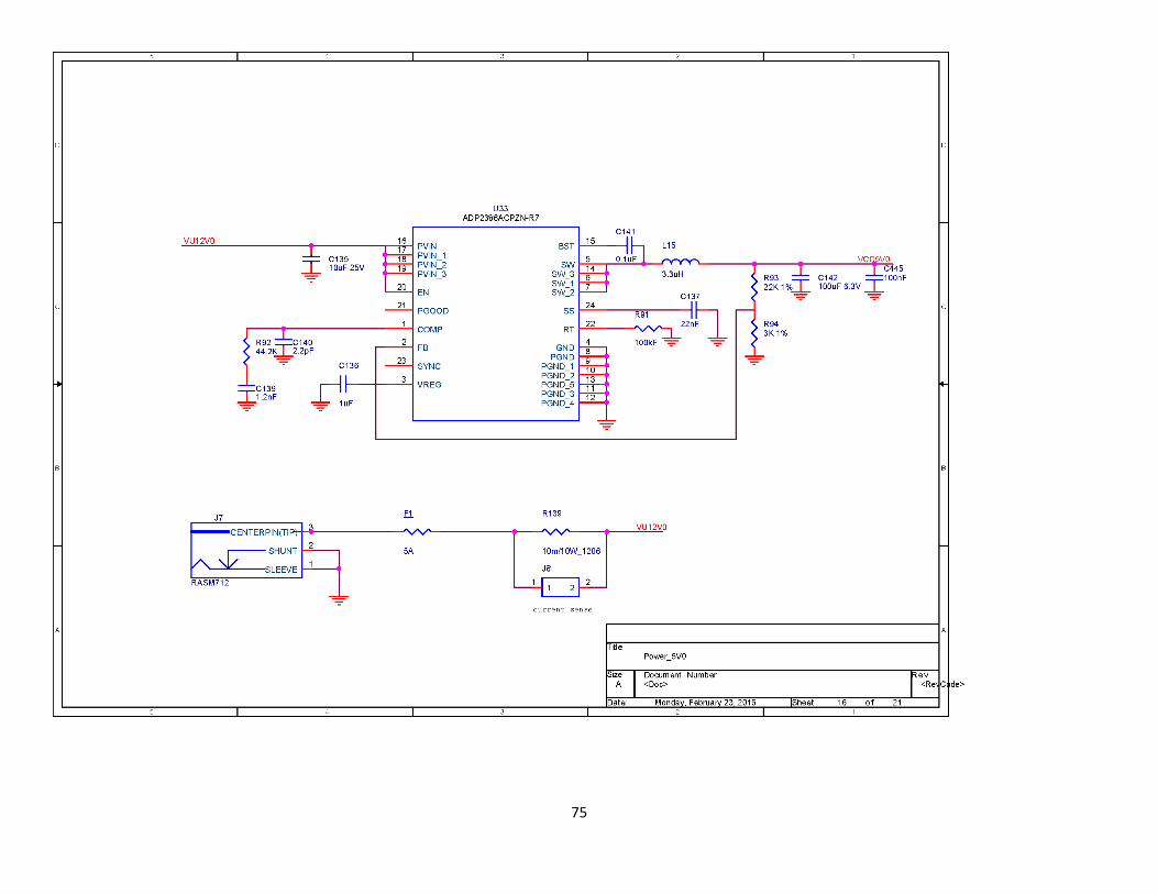
75

76

77

78

79

80

81

82

83

84

85

86

87

88

89