system level cooling, fatigue, and durability analysis … · system level cooling, fatigue, and...
TRANSCRIPT

System Level Cooling, Fatigue, and Durability
Analysis via MultiphysicsAnalysis via MultiphysicsCo-SimulationStuart A. Walker, Ph.D.

Outline
• Motivation• Presentation of process• Presentation of tools• Presentation of the results• Presentation of the results
2

Importance of External Automotive Aerodynamics via CFD
Cooling• Engine• Transmission• Brakes
Comfort• Ventilation• Heating• Air conditioning• Wind noise
Stability• Directional• Cross wind sensitivity
Visibility• Dirt (soiling)• Splash/spray• Wiper lift off
Performance
3
• Brakes• Condenser
Performance• Fuel economy• Emission• Max. speed• Acceleration
downforce
dragforce
Spoiler oscillation, FSI
Aero acoustics (CAA)

Importance of System Level Modeling• Many important component level
responses – Temperature– Stress– Displacement
• Component responses are coupled via external aerodynamics,
Rotor/Brake Pad Friction
(hot side boundary conditions)
Rotor/Brake Pad Friction
(hot side boundary conditions)
External Aerodynamics
(cold side boundary conditions)
External Aerodynamics
(cold side boundary conditions)
via external aerodynamics, structural physics, and control systems
– Rotor example
4
AcuSolve Coupled Model
Heat Transfer Simulation to calculate rotor temperaturesHeat Transfer Simulation to calculate rotor temperatures
Thermo-structural Model
(durability and fatigue)
Thermo-structural Model
(durability and fatigue)

Outline
• Motivation• Presentation of process• Presentation of tools• Presentation of the results• Presentation of the results
5

Engine Block Cooling Example• Desired result:
– Temperature in engine block– Stress in engine block– Displacement in engine block
• Important CFD physics– Underhood flow for HTC on engine block– Water jacket flow for engine block cooling
• Modeling approach– Compute HTC from external aero calc– Compute temperature in solid from internal water jacket model– Compute stress/displacement in solid
6

General Approach
Subcase 1:
• Bolt Pretension in Head Bolts
Subcase 1:
• Bolt Pretension in Head Bolts
Thermo-structural Model
Combustion Simulation
(hot side boundary conditions)
Combustion Simulation
(hot side boundary conditions)
Heat Transfer Simulation to calculate Heat Transfer Simulation to calculate
7
AcuSolve Coupled Model
Subcase 2:
• Lock Pre-tension Displacements• Apply Temperature Loading
Subcase 2:
• Lock Pre-tension Displacements• Apply Temperature Loading
Subcase 3:
• Lock Pre-tension Displacements• Continue Temperature Loading• Apply Combustion Pressure Loading
Subcase 3:
• Lock Pre-tension Displacements• Continue Temperature Loading• Apply Combustion Pressure Loading
Heat Transfer Simulation to calculate Engine Temperature loading
Heat Transfer Simulation to calculate Engine Temperature loading
External Aerodynamic Simulation
(cold side boundary conditions)
External Aerodynamic Simulation
(cold side boundary conditions)
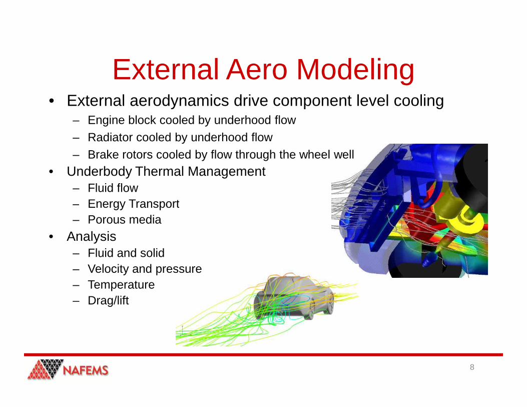
External Aero Modeling• External aerodynamics drive component level cooling
– Engine block cooled by underhood flow– Radiator cooled by underhood flow– Brake rotors cooled by flow through the wheel well
• Underbody Thermal Management– Fluid flow– Energy Transport– Energy Transport– Porous media
• Analysis– Fluid and solid – Velocity and pressure– Temperature– Drag/lift
8

Component Level ModelingComponent designs
– Exhaust systems– Radiator– Blower/Fans– Water jacket HX
Detailed analysis– Fluid and solid– Fluid and solid– Velocity and Pressure– Temperature
9

System Level Modeling• Thermal management
– External aerodynamics– Component level modeling
• Coupling for stress analysis– AcuSolve– Radioss
Friction / Motor Dissipation / Combustion
(hot side boundary conditions)
Friction / Motor Dissipation / Combustion
(hot side boundary conditions)
External Aero/HX Simulation
(cold side boundary conditions)
External Aero/HX Simulation
(cold side boundary conditions)
10
AcuSolve Coupled Model
Heat Transfer Simulation to calculate Engine Loading
Heat Transfer Simulation to calculate Engine Loading
Thermo-structural Model
(durability and fatigue)
Thermo-structural Model
(durability and fatigue)
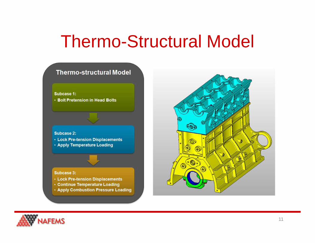
Thermo-Structural Model
11

Outline
• Motivation• Presentation of process• Presentation of tools• Presentation of the results• Presentation of the results
12
Modeling and Visualization Tools
• “One team – One solution”• Altair Engineering, Inc.
– HyperWorks Suite provides an integrated environment for pre/solve/post for system environment for pre/solve/post for system level vehicle coupling of FEA, CFD, MBD, and NVH physics
13

Pre-Processing• AcuConsole
– Dedicated pre-processor for AcuSolve– Fast and robust CFD meshing (e.g. 90Mio tetras external automotive
80min)
• HyperMesh– Solver neutral CFD grid generator
14
– Solver neutral CFD grid generator– Powerful geometry cleanup/generation tools– One pre-processor for structural and CFD analysis
HyperMesh AcuConsole

Solver• Radioss CFD/FSI
– Explicit multi-physics solver– Coupled solver (structure + fluid)– Suited for compressible flow
• AcuSolve– Implicit multi-purpose CFD solver– Implicit multi-purpose CFD solver– Finite element based– Strong FSI capabilities (P-FSI, DC-FSI)
15
Courtesy of HTTAcuSolve Radioss

AcuSolve• General
– General purpose, 3-dimensional, unstructured CFD solver
– Based on Finite Element method (Galerkin Least Square, GLS)
• Originated at Stanford University by Prof. T.J.R. Hughes et. al. and further improved for industrial applications
– Incompressible, weakly compressible Navier Stokes solver
• Numerics
– 2nd order accuracy (space and time) for all flow variables
– Scalable (e.g. customer runs on 1024 CPUs, 350Mio cells)
– Various turbulence models available (RANS, LES, DES)
– Transient / steady state
– Solving the fully coupled system
– Sliding mesh (rotating machinery)
– Moving/deforming mesh, ALE (Fluid-Structure)
16
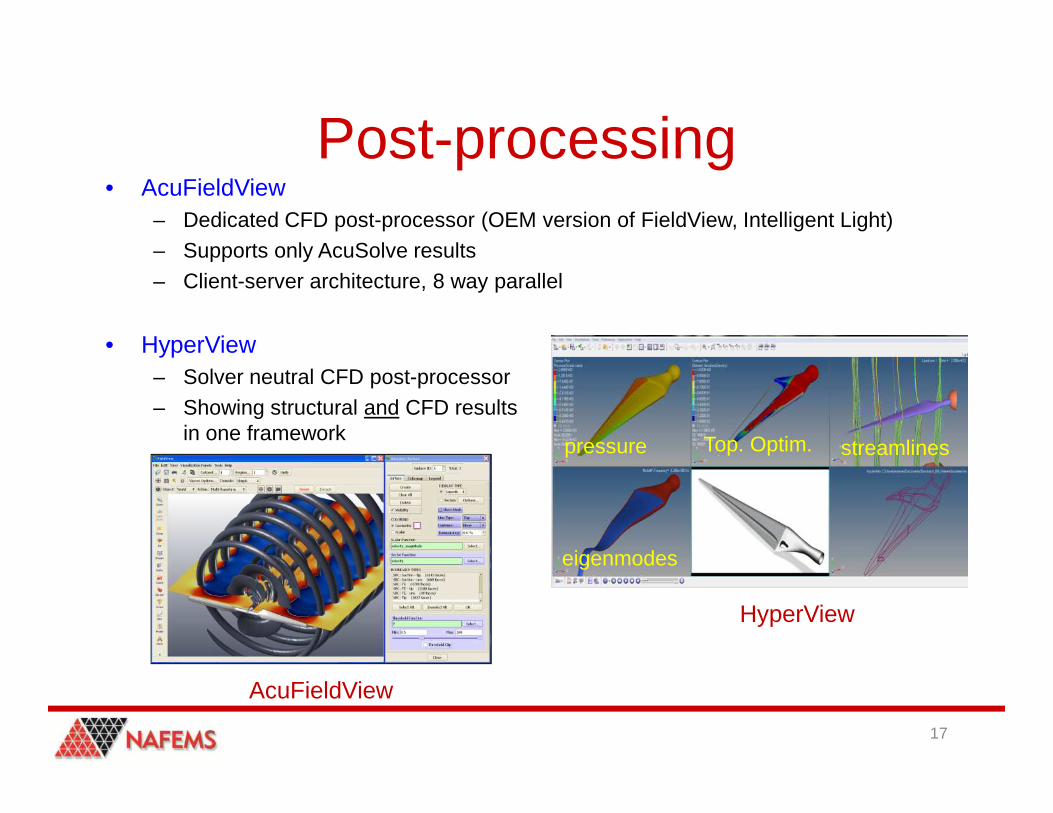
Post-processing• AcuFieldView
– Dedicated CFD post-processor (OEM version of FieldView, Intelligent Light)– Supports only AcuSolve results– Client-server architecture, 8 way parallel
• HyperView– Solver neutral CFD post-processor– Showing structural and CFD results – Showing structural and CFD results
in one framework
17
HyperView
eigenmodes
pressure Top. Optim. streamlines
AcuFieldView

CFD Optimization with HyperWorksInitial design Morphing Optimization Optimized design
18
Cw = 0.04Cw = 1
UI = 0.83 UI = 0.94

Component Level OptimizationSuccess Story (CFD optimization)
Case: Exhaust system, catalytic converterObjective: uniform flow, min. pressure dropResult: uniformity +12%, pressure drop -16%
19
Case: Engine compressor, impeller bladeObjective: maximize pressure ratioResult: pressure ratio +5.6%,
Case: Evaporator, HVAC systemObjective: uniform flow, min. pressure dropResult: uniformity +5.6%, pressure drop -7%

Outline
• Motivation• Presentation of process• Presentation of tools• Presentation of the results• Presentation of the results
20

External Aero Solution• Closed shell mesh generated in HyperMesh
– Shell mesh boolean– CFD wrapping
• Starting point for “The Virtual Wind Tunnel”– Ease of use– AcuSolve behind the scenes
21

External Aero Solution
22

External Aero Results
23

Engine Block Loading
24

Static FEA Analysis in OptiStruct
Subcase 1:
• Bolt Pretension in Head Bolts
Subcase 1:
• Bolt Pretension in Head Bolts
Thermo-structural Model
25
Subcase 2:
• Lock Pre-tension Displacements• Apply Temperature Loading
Subcase 2:
• Lock Pre-tension Displacements• Apply Temperature Loading
Subcase 3:
• Lock Pre-tension Displacements• Continue Temperature Loading• Apply Combustion Pressure Loading
Subcase 3:
• Lock Pre-tension Displacements• Continue Temperature Loading• Apply Combustion Pressure Loading
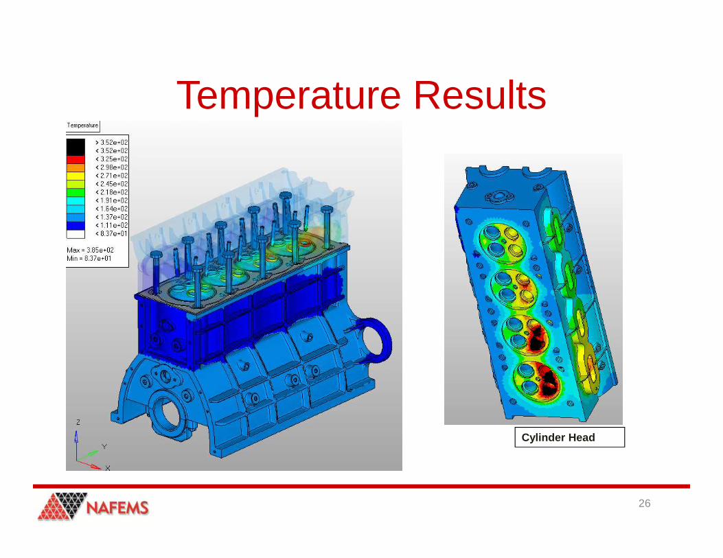
Temperature Results
26
Cylinder Head

Displacement Results
27

Stress Results
28

Contact Pressure and Bore Deformation
29

Conclusion• Altair HyperWorks Suite provides a
complete vehicle simulation package– Pre-processing
• HyperMesh/AcuConsole• Virtual Wind Tunnel
– Solver• AcuSolve – CFD• OptiStruct/Radioss – FEA• OptiStruct/Radioss – FEA
– Post-Processing• HyperView/AcuFieldView
– CFD/FEA Optimization• HyperMorph/HyperStudy
30
Stuart Walker, Ph.D. | CFD Specialist [email protected] | altair.com
Altair | Innovation Intelligence®