system interfaces for distribution management part 13: cim...
TRANSCRIPT

January 2005 / Rev08 : June 2006
****************** CDV **************
INTERNATIONAL ELECTROTECHNICAL COMMISSION
____________
System Interfaces For Distribution Management
Part 13: CIM RDF Model Exchange Format for Distribution
FOREWORD
1) The IEC (International Electrotechnical Commission) is a worldwide organization for standardization comprising all national electrotechnical committees (IEC National Committees). The object of the IEC is to promote international co-operation on all questions concerning standardization in the electrical and electronic fields. To this end and in addition to other activities, the IEC publishes International Standards. Their preparation is entrusted to technical committees; any IEC National Committee interested in the subject dealt with may participate in this preparatory work. International, governmental and non-governmental organizations liaising with the IEC also participate in this preparation. The IEC collaborates closely with the International Organization for Standardization (ISO) in accordance with conditions determined by agreement between the two organizations.
2) The formal decisions or agreements of the IEC on technical matters express, as nearly as possible, an international consensus of opinion on the relevant subjects since each technical committee has representation from all interested National Committees.
3) The documents produced have the form of recommendations for international use and are published in the form of standards, technical reports or guides and they are accepted by the National Committees in that sense.
4) In order to promote international unification, IEC National Committees undertake to apply IEC International Standards transparently to the maximum extent possible in their national and regional standards. Any divergence between the IEC Standard and the corresponding national or regional standard shall be clearly indicated in the latter.
5) The IEC provides no marking procedure to indicate its approval and cannot be rendered responsible for any equipment declared to be in conformity with one of its standards.
6) Attention is drawn to the possibility that some of the elements of this International Standard may be the subject of patent rights. The IEC shall not be held responsible for identifying any or all such patent rights.
International Standard IEC 61968 has been prepared by Working Group 14, of IEC technical committee 57: Power System Control And Associated Communications.
The text of this standard is based on the following documents:
FDIS Report on Voting
57/……. 57/…….
Full information on the voting for the approval of this standard can be found in the report on voting indicated in the above table.

CONTENTS
Scope ..............................................................................................................................4
Scope of full standard................................................................................................4
Scope of this Part ......................................................................................................4
General .....................................................................................................................5
Normative references.......................................................................................................6
Reference and Information Models...................................................................................7
Introduction ...............................................................................................................7
CIM RDF describing Distribution Networks.......................................................................8
Issues related to partial-phase devices modeling .............................................................9
Switches....................................................................................................................9
Partial phase continuity in radial networks .................................................................9
CIM Classes Used and Corresponding RDF.....................................................................10
BaseVoltage and VoltageLevel .........................................................................10
Containment hierarchy roots.............................................................................10
HV/MV Substation ............................................................................................11
MV/MV Substation ............................................................................................11
MV/LV Substation.............................................................................................11
Junction ...........................................................................................................12
Switch 12
Bay 13
BusbarSection ...........................................................................................................13
PowerTransformer .....................................................................................................14
MV/MV Transformer .........................................................................................15
Line 15
ACLineSegment ........................................................................................................16
WireArrangement ......................................................................................................16
EquivalentSource ......................................................................................................17
Compensator .............................................................................................................17
StaticVarCompensator...............................................................................................17
EquivalentLoad..........................................................................................................18
Adequation between Part 13 (CDPSM) and Part 61968-4 ..........................................21
Adequation between CDPSM and CPSM ...................................................................22
Annex A (Informative) CIM XML Document from Langdale ...............................................23
Annex B (Informative) Comparison from CIM RDF and CIM XSD (ISO ITC Working Group Architecture)..............................................................................................................26
Annex C (Informative) Key Discussion points on CIM RDF and CIM XSD (ISO ITC Working Group Architecture) ...................................................................................................27
Annex D (Informative) Conclusions and recommendations (ISO ITC Working Group Architecture)..............................................................................................................29
Annex E (informative) Example of a European Distribution Network Described through CIM RDF ..........................................................................................................................30
A Distribution Network ...............................................................................................30
Corresponding CIM RDF ...........................................................................................31
Annex F (informative) Example of a North American Distribution Network ........................38

A Distribution Network ...............................................................................................38
Annex G (informative) Comparison between CDPSM and CPSM......................................41
IEC 61968
System Interfaces For Distribution Management –
Part 13: CIM RDF Model Exchange Format for Distribution
Introduction
The IEC 61968 series of standards is intended to facilitate inter-application integration as opposed to intra-application integration. Intra-application integration is aimed at programs in the same application system, usually communicating with each other using middleware that is embedded in their underlying runtime environment, and tends to be optimized for close, real-time, synchronous connections and interactive request/reply or conversation communication models. IEC 61968, by contrast, is intended to support the inter-application integration of a utility enterprise that needs to connect disparate applications that are already built or new (legacy or purchased applications), each supported by dissimilar runtime environments. Therefore, these interface standards are relevant to loosely coupled applications with more heterogenity in languages, operating systems, protocols and management tools. This series of standards is intended to support applications that need to exchange data every few seconds, minutes, or hours rather than waiting for a nightly batch run. This series of standards, which are intended to be implemented with middleware services that exchange messages among applications, will complement, not replace utility data warehouses, database gateways, and operational stores.
As used in IEC 61968, a DMS consists of various distributed application components for the utility to manage electrical distribution networks. These capabilities include monitoring and control of equipment for power delivery, management processes to ensure system reliability, voltage management, demand-side management, outage management, work management, automated mapping and facilities management. Standards interfaces are defined for each class of applications identified in the Interface Reference Model (IRM), which is described in Part 1: Interface Architecture and General Requirements.

Scope
Scope of full standard
The IEC 61968 standard, taken as a whole, defines interfaces for the major elements of an interface architecture for Distribution Management Systems (DMS). Part 1:Interface Architecture and General Requirements, identifies and establishes requirements for standard interfaces based on an Interface Reference Model (IRM). Parts 3-10 of this standard define interfaces relevant to each of the major business functions described by the Interface Reference Model.
As used in IEC 61968, a DMS consists of various distributed application components for the utility to manage electrical distribution networks. These capabilities include monitoring and control of equipment for power delivery, management processes to ensure system reliability, voltage management, demand-side management, outage management, work management, automated mapping and facilities management.
This set of standards is limited to the definition of interfaces and is implementation independent. They provide for interoperability among different computer systems, platforms, and languages. Methods and technologies used to implement functionality conforming to these interfaces are considered outside of the scope of these standards; only the interface itself is specified in these standards.
Scope of this Part
This part 13 specifies the format and rules for exchanging modeling information based upon the CIM and related to Distribution Network Data.
The intention of this part is to allow the exchange of instance data in bulk. Thus the imported network model data should be sufficient to allow performing network connectivity analysis, including network tracing, outage analysis, load flow calculations etc….
It uses the CIM RDF Schema presented in IEC 61970-501 as the meta-model framework for constructing XML documents containing power system modeling information. The syntax of these documents is called CIM XML format. Model exchange by file transfer serves many useful purposes, specially when some applications need to have the complete network model defined. Though the format can be used for general CIM-based information exchange, in this document specific profiles (or subsets) of the CIM are identified in order to address particular exchange requirements.
General
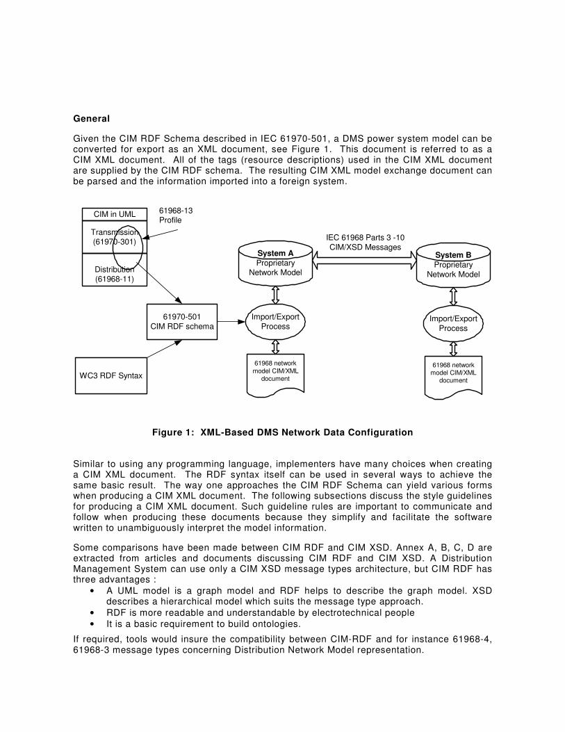
Given the CIM RDF Schema described in IEC 61970-501, a DMS power system model can be converted for export as an XML document, see Figure 1. This document is referred to as a CIM XML document. All of the tags (resource descriptions) used in the CIM XML document are supplied by the CIM RDF schema. The resulting CIM XML model exchange document can be parsed and the information imported into a foreign system.
WC3 RDF Syntax
61968-13Profile
61970-501
CIM RDF schema
Transmission(61970-301)
Distribution(61968-11)
CIM in UML
System A
ProprietaryNetwork Model
Import/Export
Process
61968 network
model CIM/XMLdocument
System B
Proprietary
Network Model
Import/Export
Process
61968 networkmodel CIM/XML
document
IEC 61968 Parts 3 -10
CIM/XSD Messages
Figure 1: XML-Based DMS Network Data Configuration
Similar to using any programming language, implementers have many choices when creating a CIM XML document. The RDF syntax itself can be used in several ways to achieve the same basic result. The way one approaches the CIM RDF Schema can yield various forms when producing a CIM XML document. The following subsections discuss the style guidelines for producing a CIM XML document. Such guideline rules are important to communicate and follow when producing these documents because they simplify and facilitate the software written to unambiguously interpret the model information.
Some comparisons have been made between CIM RDF and CIM XSD. Annex A, B, C, D are extracted from articles and documents discussing CIM RDF and CIM XSD. A Distribution Management System can use only a CIM XSD message types architecture, but CIM RDF has three advantages :
• A UML model is a graph model and RDF helps to describe the graph model. XSD describes a hierarchical model which suits the message type approach.
• RDF is more readable and understandable by electrotechnical people
• It is a basic requirement to build ontologies.
If required, tools would insure the compatibility between CIM-RDF and for instance 61968-4, 61968-3 message types concerning Distribution Network Model representation.
Normative references
The following normative documents contain provisions, which, through reference in this text, constitute provisions of this International Standard. For dated references, subsequent amendments to, or revisions of, any of these publications do not apply. However, parties to agreements based on this International Standard are encouraged to investigate the possibility of applying the most recent editions of the normative documents indicated below. For undated references, the latest edition of the normative document referred to applies. Members of IEC and ISO maintain registers of currently valid International Standards.
IEC 61970-301, EMSAPI – Part 301: Common Information Model (CIM) Base
IEC 61970-452, EMS-API – Part 452: CIM Model Exchange Specification
IEC 61970-501, EMS-API – Part 501 : CIM RDF Schema
IEC 61970-503, EMS-API – Part 503 : CIM XML Model Exchange Format
IEC 61968-1 System Interfaces for Distribution Management – Interface Architecture and General Requirements
IEC 61968-11 System Interfaces for Distribution Management- Interface Reference Model
IEC 61968-3 System Interfaces for Distribution Management- Network Operation
IEC 61968-4 System Interfaces for Distribution Management- Asset Management
IEC 60050 series: International Electrotechnical Vocabulary
W3C: RDF/XML Syntax Specification
W3C: Extensible Markup Language (XML) 1.0
W3C: XSL Transformations (XSLT)
W3C: Document Object Model (DOM)

Reference and Information Models
Introduction
The message types defined in the 61968 series of standards are based on a logical partitioning of the DMS business functions and components called the IEC 61968 Interface Reference Model.
The contents of the message types are based on a static information model to ensure consistency of field names and data types. Each message type is defined as a set of fields copied from the information model classes. The message types defined in this standard are intended to satisfy a majority of typical applications. In some particular project implementations, it may be desirable to modify the set of fields using a methodology such as that described in Part 1.

CIM RDF describing Distribution Networks
In this part of the 61968 standard, we intend to describe a CIM RDF model for the Distribution networks. It has the same objective as the NERC Common Power System Model (CPSM) Profile that has been agreed to at the Transmission level (reference : http://www.w3.org/TR/2004/REC-rdf-primer-20040210 §6.5, and 61970-452). At the Distribution level, there exist several kinds of applications concerned such as Network Operation, Asset Management, Customer Information, Network Planning, Work Management, etc. Efforts on standardization of these applications are conducted at the IEC through the Technical Committee 57 and Working Group 14 (System Interfaces for Distribution management). For more information please refer to http://www.cimuser.org web site. Electric utilities use power system models for a number of different purposes. For example, power system simulations are developed for planning and security analysis. An operational power system model may consist of thousands of classes of information. In addition to using these models in-house, applications inside an individual utility need to exchange system modelling information, both for planning and operational purposes (e.g. coordinating transmission and distribution networks and ensuring reliable operations). However, individual utilities use different software packages for these purposes. As a result, the system models are stored in different formats, making exchange among these models a hard work. The exchange of model data is difficult and requires specific interface development for data exchange between each pair of applications. Consequently, the individual utilities recognize the need to agree on common definitions of the power system entities and relationships to facilitate the future data exchange requirements. The CIM defines most of objects inside an electric utility as classes and attributes, as well as the relationships among them. The CIM uses these object classes, their attributes and relationships to support the integration of independently developed applications among vendor specific DMS applications. CIM represents a canonical data model to support data exchange between each part of a DMS system such as asset management, distribution planning, etc.. Based on the NERC CPSM Profile for the transmission network, this part proposes a CIM-RDF profile for modelling Distribution networks. This part defines a CDPSM profile (Common Distribution Power System Model). This document will mention the differences between this part and CPSM profile when they occur. Consequently the proposal is mainly based on 61970-301 part, without, at the present time, the Asset class found in 61968. In the future, assetType attribute of Asset class will be used instead of PsrType if CIM 61968-11 is normalized and incorporated officially in the CIM. In this proposal, class Location is defined in the 61968 packages.
The proposal is valid for three-phase balanced and unbalanced distribution networks. It is described as a single phase network and may have single- or two-phase components such as single-phase laterals and transformers1. However, some users may find it convenient to restrict the proposed profile to include only the subset of three-phase balanced networks and exclude support for single phase components. In the sections which follow the term “partial-phase devices” is used to describe components having less than three phases.
——————— 1 The US radial electric distribution system is typically unbalanced. The main distribution feeder is three-phased with single-phased tapped load. The model exchange format should support a three-phased, unbalanced model to support, as an example, unbalanced load flow calculations.
Issues related to partial-phase devices modeling
The IEC 61970-301 standard already has support for partial phase conducting devices through the phase-code attribute which may be a combination of any or all of the letters A, B, C, and N. In general one can think of a partial phase conducting device as being the same as a full 3-phase device with some of the phases missing.
Impedances of unbalanced and partial phase devices
61970-301 specifies impedance of conducting devices in terms of the real and reactive positive and zero sequence impedance. Unfortunately, this is only valid for perfectly symmetric three-phase networks where all 3 phases have the same value of self-impedance and the same mutual impedance value.
The impedance of unbalanced 3-phase conducting devices such as AC line segments must be specifed as a three by three complex matrix where the diagonal terms specify the self impedance of each phase and the off-diagonal terms specify the mutual impedance between each phase pair. These values can be computed using Carson’s equations based on the geometric mean radius, the linear resistance and the geometric arangement of the three phases on the pole. 61970-301 provides all the parameters necessary in the Conductor and WireArrangement classes. For 2-phase devices the impedance matrix is two by two and for single-phase devices it is a complex scalar specifying the self impedance of the single phase conductor.
Switches
61970-301 allows only two states for a switch device, i.e. open and closed. Thus for a 3-phase switch it suggests that all three phases of the switch always operate together and it does not support the situation where, for example, phase A of the switch is open while phases B and C are closed. Of course a single-phase switch may be open or closed.
Partial phase continuity in radial networks
Many distribution networks are operated radially meaning that there is only one path for power to be supplied to any conducting device. For all phases of a device in a radial network to be properly energized all devices upstream must have the same phases present. (For example it is not possible to energize all the phases of a three phase device via a partial phase upstream device.)
However, this requirement is not enforced in this specification. Rather it is up to the importing DMS to check if this requirement is satisfied throughout the network

CIM Classes Used and Corresponding RDF
There is a large variety of voltage combinations in a substation. Also, in general substations may contain one, two or more voltage levels. The applications needing such “substation type” information will deduce the substation type from the voltage levels it contains
In general substations may contain one, two or more voltage levels, the substation type will be deduced by analyzing the voltage levels a substation contains.The class PSRType can be used to distinguish these different substations. Class Location can be used to define the absolute position of a Substation.
Annex E gives a complete example of a Distribution Network Data represented through CIM-RDF.
This document is aligned to CIM Model version 10.7, CPSM 2.0 profile, and 61970-452. From the standpoint of a data producer (exporter), the document describes a minimum subset of CIM classes and class data which must be present in an XML formatted data file to comply with CDPSM Minimum Data Requirements. From the standpoint of a data recipient (importer), the document describes a subset of the CIM that an importer could reasonably expect to receive in an XML data file designed to be compliant with the CDPSM Minimum Data Requirements.
BaseVoltage and VoltageLevel
For every operating voltage found in the network we create a BaseVoltage. An ACLineSegment is associated to a BaseVoltage. A TransformerWinding is associated to a BaseVoltage. PowerTransformer should be contained in a Substation.
Every Substation is associated with one or more VoltageLevel-s, each of which is in turn associated with the corresponding BaseVoltage.
All the objects of the network, except ACLineSegment, PowerTransformer and TransformerWinding should be contained within a VoltageLevel.
<cim:BaseVoltage rdf:ID="BaseVoltage_1"> <cim:BaseVoltage.nominalVoltage>63</cim:BaseVoltage.nominalVoltage>
</cim:BaseVoltage> <cim:BaseVoltage rdf:ID="BaseVoltage_2">
<cim:BaseVoltage.nominalVoltage>42</cim:BaseVoltage.nominalVoltage> </cim:BaseVoltage> <cim:VoltageLevel rdf:ID="VL_1">
<cim:Naming.name>NOD10S61</cim:Naming.name> <cim:VoltageLevel.MemberOf_Substation rdf:resource="#Substation_1"/> <cim:VoltageLevel.BaseVoltage rdf:resource="#BaseVoltage_1"/>
</cim:VoltageLevel> <cim:VoltageLevel rdf:ID="VL_2">
<cim:Naming.name>NOD10S62</cim:Naming.name> <cim:VoltageLevel.MemberOf_Substation rdf:resource="#Substation_1"/> <cim:VoltageLevel.BaseVoltage rdf:resource="#BaseVoltage_2"/>
</cim:VoltageLevel>
Containment hierarchy roots
The CPSM 2.0 profile of base CIM defines HostControlArea to be at the root of containment hierarchy. In contrast, this specification defines HV/MV Substation as the root of the containment hierarchy.
HV/MV Substation
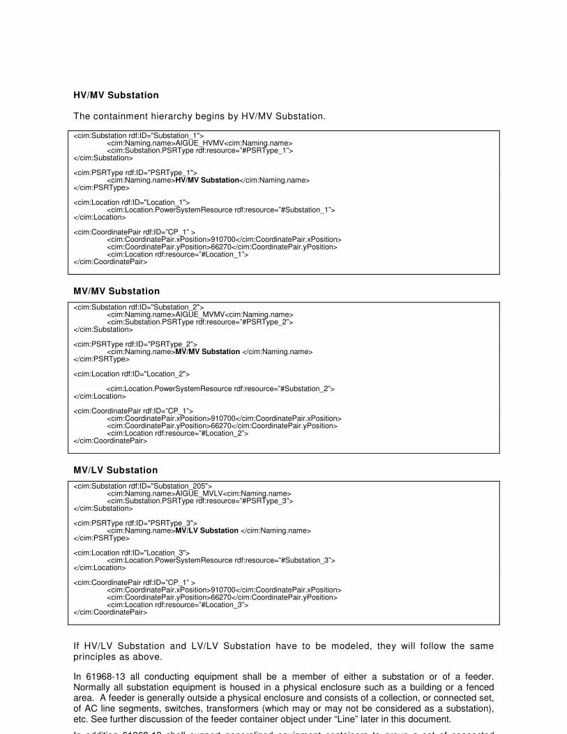
The containment hierarchy begins by HV/MV Substation.
<cim:Substation rdf:ID="Substation_1"> <cim:Naming.name>AIGUE_HVMV<cim:Naming.name> <cim:Substation.PSRType rdf:resource=”#PSRType_1”> </cim:Substation> <cim:PSRType rdf:ID="PSRType_1"> <cim:Naming.name>HV/MV Substation</cim:Naming.name> </cim:PSRType> <cim:Location rdf:ID="Location_1">
<cim:Location.PowerSystemResource rdf:resource=”#Substation_1”> </cim:Location> <cim:CoordinatePair rdf:ID=”CP_1” >
<cim:CoordinatePair.xPosition>910700</cim:CoordinatePair.xPosition> <cim:CoordinatePair.yPosition>66270</cim:CoordinatePair.yPosition> <cim:Location rdf:resource=”#Location_1”> </cim:CoordinatePair>
MV/MV Substation
<cim:Substation rdf:ID="Substation_2"> <cim:Naming.name>AIGUE_MVMV<cim:Naming.name> <cim:Substation.PSRType rdf:resource=”#PSRType_2”> </cim:Substation> <cim:PSRType rdf:ID="PSRType_2"> <cim:Naming.name>MV/MV Substation </cim:Naming.name> </cim:PSRType> <cim:Location rdf:ID="Location_2">
<cim:Location.PowerSystemResource rdf:resource=”#Substation_2”>
</cim:Location> <cim:CoordinatePair rdf:ID=”CP_1”>
<cim:CoordinatePair.xPosition>910700</cim:CoordinatePair.xPosition> <cim:CoordinatePair.yPosition>66270</cim:CoordinatePair.yPosition> <cim:Location rdf:resource=”#Location_2”> </cim:CoordinatePair>
MV/LV Substation
<cim:Substation rdf:ID="Substation_205"> <cim:Naming.name>AIGUE_MVLV<cim:Naming.name> <cim:Substation.PSRType rdf:resource=”#PSRType_3”> </cim:Substation> <cim:PSRType rdf:ID="PSRType_3"> <cim:Naming.name>MV/LV Substation </cim:Naming.name> </cim:PSRType> <cim:Location rdf:ID="Location_3"> <cim:Location.PowerSystemResource rdf:resource=”#Substation_3”> </cim:Location> <cim:CoordinatePair rdf:ID=”CP_1” >
<cim:CoordinatePair.xPosition>910700</cim:CoordinatePair.xPosition> <cim:CoordinatePair.yPosition>66270</cim:CoordinatePair.yPosition> <cim:Location rdf:resource=”#Location_3”> </cim:CoordinatePair>
If HV/LV Substation and LV/LV Substation have to be modeled, they will follow the same principles as above.
In 61968-13 all conducting equipment shall be a member of either a substation or of a feeder. Normally all substation equipment is housed in a physical enclosure such as a building or a fenced area. A feeder is generally outside a physical enclosure and consists of a collection, or connected set, of AC line segments, switches, transformers (which may or may not be considered as a substation), etc. See further discussion of the feeder container object under “Line” later in this document.
In addition 61968-13 shall support generalized equipment containers to group a set of connected

conducting devices – for example the CompositeSwitch device of 61970-301.
Junction
In the CIM, devices are connected to each other by connecting a terminal of a device to a common ConnectivityNode. A connectivity node may have any number of terminals connected to it.
In a Distribution network most ConnectivityNodes are contained in substations. However in some cases (e.g. a tapped distribution line), ConnectivityNodes may be located on lines which are outside of substations. 61970-301 defines the Junction class to indicate such connectivity nodes. In this case, the ConnectivityNode and the Junction must be located in a virtual Substation.
However, a typical distribution network generally has many connectivity nodes outside of substations along a feeder. Since these connectivity nodes serve no purpose other than to connect two or more devices it is generally not necessary to also specify them as a Junction.
Switch2
Switches are contained either by VoltageLevel or by Bay. . If Switches are contained by VoltageLevel, Bay are not required. The abstract Switch is used only when we do not know the detailed class.
61968-13 supports the following kinds of Switch devices:
- Breaker (exist in CPSM) able to interrupt fault currents greater than normal load currents.
- LoadBreakSwitch (exist in CPSM) able to interrupt normal load currents only
- Disconnector (exist in CPSM) no current interrupt capability
- Fuse (doesn’t exist in CPSM) able to interrupt fault currents
- Jumper (doesn’t exist in CPSM)
- GroundDisconnector (doesn’t exist in CPSM)
<cim:BaseVoltage rdf:ID="BaseVoltage_1"> <cim:BaseVoltage.nominalVoltage>63</cim:BaseVoltage.nominalVoltage>
</cim:BaseVoltage> <cim:VoltageLevel rdf:ID="VL_1">
<cim:Naming.name>NOD10S61</cim:Naming.name> <cim:VoltageLevel.MemberOf_Substation rdf:resource="#Substation_1"/> <cim:VoltageLevel.BaseVoltage rdf:resource="#BaseVoltage_1"/>
</cim:VoltageLevel> <cim:Substation rdf:ID="Substation_10">
<cim:Naming.name>AIGUE_HVMV<cim:Naming.name> <cim:Substation.PSRType rdf:resource=”#PSRType_1”>
</cim: Substation > <cimBreaker rdf:ID="Switch_1"> <cim:Naming.name>73109J0001<cim:Naming.name> <cim:Switch.normalOpen>false</cim:Switch.normalOpen> <cim:Equipment.MemberOf_EquipmentContainer rdf:resource="#VL_1"> </cim:Breaker> <cim:Location rdf:ID="Location_5">
<cim:Location.PowerSystemResource rdf:resource=”#Substation_1”> </cim:Location> <cim:CoordinatePair rdf:ID=”CP_1”>
<cim:CoordinatePair.xPosition>909255.1</cim:CoordinatePair.xPosition> <cim:CoordinatePair.yPosition>56999</cim:CoordinatePair.yPosition> <cim:Location rdf:resource=”#Location_5”> </cim:CoordinatePair>
——————— 2 this should be forbidden, switch is an abstract class.

Bay
61970-301 supports the Bay object as a collection or container of a set of switch devices and connectivity nodes inside a substation. Generally a substation will contain several, usually identical, bays containing connectivity nodes for incoming or outgoing lines (feeders) Outgoing and incoming feeders are distinguished by the class PSRType. (PSR Type & Location are nonmandatory)
This data is not mandatory. If Switches are contained by VoltageLevel, Bay is not required.
<cim:BaseVoltage rdf:ID="BaseVoltage_1"> <cim:BaseVoltage.nominalVoltage>63</cim:BaseVoltage.nominalVoltage>
</cim:BaseVoltage> <cim:VoltageLevel rdf:ID="VL_1">
<cim:Naming.name>NOD10S61</cim:Naming.name> <cim:VoltageLevel.MemberOf_Substation rdf:resource="#Substation_1"/> <cim:VoltageLevel.BaseVoltage rdf:resource="#BaseVoltage_1"/>
</cim:VoltageLevel> <cim:Substation rdf:ID="Substation_10">
<cim:Naming.name>AIGUE_HVMV<cim:Naming.name> <cim:Substation.PSRType rdf:resource=”#PSRType_1”>
</cim: Substation > <cim:Bay rdf:ID="Bay_1">
<cim:Naming.name>AIGUEC0601<cim:Naming.name> <cim:Bay.MemberOf_Substation rdf:resource="#VL_1">
<cim:PowerSystemResource.PSRType rdf:resource=”#PSRType_5”> </cim:Bay> <cim:PSRType rdf:ID="PSRType_5"> <cim:Naming.name>OUTGOING FEEDER</cim:Naming.name> </cim:PSRType> <cim:Breaker rdf:ID="Breaker_1"> <cim:Naming.name>AIGUEC0601<cim:Naming.name> <cim:Switch.normalOpen>false</cim:Switch.normalOpen> <cim:Equipment.MemberOf_EquipmentContainer rdf:resource="#Bay_1"> </cim:Breaker> <cim:Location rdf:ID="Location_6">
<cim:Location.PowerSystemResource rdf:resource=”#Bay_1”> </cim:Location> <cim:CoordinatePair rdf:ID=”CP_1”>
<cim:CoordinatePair.xPosition>910696</cim:CoordinatePair.xPosition> <cim:CoordinatePair.yPosition>66272</cim:CoordinatePair.yPosition> <cim:Location rdf:resource=”#Location_6”> </cim:CoordinatePair>
BusbarSection
BusbarSection
Terminal
ConnectivityNode
<cim:BaseVoltage rdf:ID="BaseVoltage_1"> <cim:BaseVoltage.nominalVoltage>63</cim:BaseVoltage.nominalVoltage>
</cim:BaseVoltage> <cim:VoltageLevel rdf:ID="VL_1">
<cim:Naming.name>NOD10S61</cim:Naming.name> <cim:VoltageLevel.MemberOf_Substation rdf:resource="#Substation_1"/> <cim:VoltageLevel.BaseVoltage rdf:resource="#BaseVoltage_1"/>
</cim:VoltageLevel> <cim:Substation rdf:ID="Substation_10">
<cim:Naming.name>AIGUE_HVMV<cim:Naming.name> <cim:Substation.PSRType rdf:resource=”#PSRType_1”>
</cim: Substation >
<cim:BusbarSection rdf:ID="BusbarSection_1"> <cim:Naming.name>AIGUEB0001<cim:Naming.name> <cim:Equipment.MemberOf_EquipmentContainter rdf:resource="#VL_1"> </cim:BusbarSection>

<cim:Terminal rdf:ID=”Terminal_1”> <cim:Terminal.ConductingEquipment rdf:resource="#BusbarSection_1"/> <cim:Terminal.ConnectivityNode rdf:resource="#CN_1"/>
</cim:Terminal> <cim:ConnectivityNode rdf:ID=”CN_1”>
<cim: ConnectivityNode.MemberOf_EquipmentContainer rdf:resource=”#Substation_1”> </cim:ConnectivityNode> <cim:Location rdf:ID="Location_7">
<cim:Location.PowerSystemResource rdf:resource=”#BusbarSection_1”> </cim:Location>
<cim:CoordinatePair rdf:ID=”CP_1”>
<cim:CoordinatePair.xPosition>910720</cim:CoordinatePair.xPosition> <cim:CoordinatePair.yPosition>66290</cim:CoordinatePair.yPosition> <cim:Location rdf:resource=”#Location_7”>
</cim:CoordinatePair>
PowerTransformer
61968-13 supports transformer objects and their tap changers exactly as defined in 61970-301.
While an Autotransformer in reality does not have two distinct windings, it is acceptable in 61968-13 to model it as having two windings similar to conventional transformers in order to define the voltage ratio. However, in distribution systems, line voltage regulators are sometimes used to compensate for line voltage drop. Line voltage regulators frequently are Autotransformers with a nominal 1:1 voltage ratio but generally operate at slightly off-nominal taps to provide a voltage boost. There is a special problem defining the leakage impedance of such devices since at nominal tap position the leakage impedance is essentially zero. Therefore for autotransformers with a nominal 1:1 voltage ratio the leakage impedance shall be defined with the tap at maximum tap position.
There are dozens of distribution transformer winding configurations which cannot be simply transformed into Y-Y equivalents as is commonly done for balanced transmission modeling. Therefore, more information is needed than is provided below in order to accurately model many transformer types. However, comprehensive transformer modeling would push the size and detail of the profile beyond practical usability. Depending on the need, Kersting IEEE models could be used as a guide to an appropriate level of transformer detail to extend this profile.
Here are the associations for PowerTransformer containment : Substation -> PowerTransformer -> TransformerWinding
The TransformerWinding -> BaseVoltage link should be used. The model needs only BaseVoltage instances that correspond to TransformerWinding’s voltage levels.
<cim:BaseVoltage rdf:ID="BaseVoltage_2">
<cim:BaseVoltage.nominalVoltage>42</cim:BaseVoltage.nominalVoltage> </cim:BaseVoltage> <cim:BaseVoltage rdf:ID="BaseVoltage_3">
<cim:BaseVoltage.nominalVoltage>20</cim:BaseVoltage.nominalVoltage> </cim:BaseVoltage> <cim:PowerTransformer rdf:ID="PowerTransformer_1"> <cim:Naming.name>AIGUEY0001<cim:Naming.name> <cim: PowerTransformer.MemberOf_ Substation rdf:resource="#SubStation_1"> </cim:PowerTransformer> <cim:TransformerWinding rdf:ID="TransformerWinding_1"> <cim:TransformerWinding.MemberOf_PowerTransformer rdf:resource="#PowerTransformer_1">
<cim:ConductingEquipment.BaseVoltage rdf:resource="#BaseVoltage_2"/> <cim:TransformerWinding.windingType rdf:resource="http://iec.ch/TC57/2005/CIM-schema-
cim10#WindingType.primary"/> <cim:TransformerWinding.ratedKV>42</cim:TransformerWinding.ratedKV>
<cim:TransformerWinding.ratedMVA>20</cim:TransformerWinding.ratedMVA> <cim:TransformerWinding.r>0.068</cim:TransformerWinding.r> <cim:TransformerWinding.x>1.89</cim:TransformerWinding.x> <cim:TransformerWinding.g>29</cim:TransformerWinding.g> <cim:TransformerWinding.shortTermMVA>22</cim:TransformerWinding.shortTermMVA >
</cim:TransformerWinding> <cim:TransformerWinding rdf:ID="TransformerWinding_2"> <cim:TransformerWinding.MemberOf_PowerTransformer rdf:resource="#PowerTransformer_1">
<cim:ConductingEquipment.BaseVoltage rdf:resource="#BaseVoltage_3"/> <cim:TransformerWinding.windingType rdf:resource="http://iec.ch/TC57/2005/CIM-schema-

cim10#WindingType.secondary"/> <cim:TransformerWinding.ratedKV>20</cim:TransformerWinding.ratedKV>
<cim:TransformerWinding.ratedMVA>20</cim:TransformerWinding.ratedMVA> <cim:TransformerWinding.r>0.08 </cim:TransformerWinding.r> <cim:TransformerWinding.x>1.2</cim:TransformerWinding.x> <cim:TransformerWinding.g>29</cim:TransformerWinding.g> <cim:TransformerWinding.shortTermMVA>22</cim:TransformerWinding.shortTermMVA >
</cim:TransformerWinding> <cim:Location rdf:ID="Location_8">
<cim:Location.PowerSystemResource rdf:resource=”#PowerTransformer_1”> </cim:Location>
<cim:CoordinatePair rdf:ID=”CP_1”>
<cim:CoordinatePair.xPosition>910720</cim:CoordinatePair.xPosition> <cim:CoordinatePair.yPosition>66290</cim:CoordinatePair.yPosition>
<cim:Location rdf:resource=”#Location_8”> </cim:CoordinatePair>
MV/MV Transformer
A MV/MV transformer or auto-transformer is a PowerTransformer as described above.
Line
In 61970-301 a line is a conductor connecting nodes usually in two different substations. However, 61970-301 also allows for the modeling of a tapped line connecting more than two substations, but it imposes the requirement that the tap junction be contained in a “dummy” or collapsed (or fictitious) substation.
In distribution networks it is more common to use the term “feeder” instead of the term ”line”. A feeder can be considered as a tapped line having, in general, several ACLineSegments, junctions or taps. In addition a feeder may also contain switch devices, MV/LV distribution transformers, capacitors, line voltage regulators. Because of this potentially large number of junctions it is considered impractical to insist that all such devices and junctions be contained in a substation. Instead it is sufficient to indicate them as members of a feeder only. However, it is also acceptable to model feeder devices, such as an MV/LV transformer and related switches, to be contained in a distribution substation which in turn is a member of a feeder. A Substation can’t be a member of a feeder or a line. If there is a Substation, it is necessary to split the feeder or the line into two different feeders or lines. To be consistent with CPSM, any ConnectivityNode and any equipment except ACLineSegment, PowerTransformer and TransformerWinding should be in a VoltageLevel itself in a Substation. PowerTransformer and TransformerWinding should be in a Substation.
Each Line has a list of coordinatePair. The list of coordinatePair-s in the file reflects a precise order, if the line has to be drawn.
<cim:BaseVoltage rdf:ID="BaseVoltage_2"> <cim:BaseVoltage.nominalVoltage>42</cim:BaseVoltage.nominalVoltage>
</cim:BaseVoltage> <cim:Line rdf:ID="Line_70"> <cim:Naming.description>AIGUE0001</cim:Naming.description> </cim:Line> <cim:ACLineSegment rdf:ID="ACLine1234"> <cim:Conductor.bch>0.0049480041</cim:Conductor.bch> <cim:Conductor.length>63</cim:Conductor.length> <cim:Conductor.r>0.0078750001</cim:Conductor.r> <cim:Conductor.x>0.0063</cim:Conductor.x> <cim:Conductor.ConductorType rdf:resource="#CT1237"/> <cim:ACLineSegment.MemberOf_Line rdf:resource="#Line_70"/> <cim:ConductingEquipment.BaseVoltage rdf:resource="#BaseVoltage_2"/> </cim:ACLineSegment> <cim:Location rdf:ID="Location_85">
<cim:Location.PowerSystemResource rdf:resource=”#Line_70”> </cim:Location> <cim:CoordinatePair rdf:ID="CP1085"> <cim:CoordinatePair.xPosition>908058.1</cim:CoordinatePair.xPosition> <cim:CoordinatePair.yPosition>64395.6</cim:CoordinatePair.yPosition> <cim:CoordinatePair.Location rdf:resource="# Location_85"/>

</cim:CoordinatePair> <cim:CoordinatePair rdf:ID="CP1086"> <cim:CoordinatePair.xPosition>908574</cim:CoordinatePair.xPosition> <cim:CoordinatePair.yPosition>63368</cim:CoordinatePair.yPosition> <cim:CoordinatePair. Location rdf:resource="# Location_85"/> </cim:CoordinatePair>
ACLineSegment
We must distinguish between Asset characteristics of the Line Segment and the operational (PowerSystemResource) characteristics of the Line Segment. For instance the maximum ampacity can be modeled by the amprating attribute of WireType class (Current carrying capacity, expressed in amperes, of a wire or cable under stated thermal conditions). To reflect the operational value of this attribute, then a Measurement can be used with Limit and LimitSet classes.
WireArrangement
The WireArrangement needs an enumeration of phase in order to make the Carsion’s Equations calculations for impedances. Currently one WireArrangement is needed per each phase and neutral of an ACLineSegment. Eventually this information should be moved into the Assets package, including each phase’s x,y position where ground level is assumed to be at y= 0 for reference.
For a balanced 3 or 4 wire case, an ACLineSegment instance is described as follows :
<cim:BaseVoltage rdf:ID="BaseVoltage_2"> <cim:BaseVoltage.nominalVoltage>42</cim:BaseVoltage.nominalVoltage>
</cim:BaseVoltage> <cim:ACLineSegment rdf:ID="ACLineSegment_1"> <cim:ACLineSegment.MemberOf_Line rdf:resource="#Line_1"> <cim:Conductor.length>63</cim:Conductor.length> <cim:ACLineSegment.r>0.125000</cim:ACLineSegment.r> <cim:ACLineSegment.x>0.100000</cim:ACLineSegment.x> <cim:ACLineSegment.b0ch>250</cim:ACLineSegment.bg0ch> <cim:ConductingEquipment.phases>ABC</cim:ConductingEquipment.phases> <cim:Conductor.ConductorType rdf:resource=”#ConductorType_1”>
<cim:ConductingEquipment.BaseVoltage rdf:resource="#BaseVoltage_2"/> </cim:ACLineSegment> <cim:WireArrangement rdf:ID=”WireArrangement_1”> <cim: WireArrangement.WireType rdf:resource=”#WireType_1”> <cim: WireArrangement.ConductorType rdf:resource=”#ConductorType_1”> </cim:WireArrangement> <cim:ConductorType rdf:ID=”ConductorType_1”/> <cim:WireType rdf:ID=”WireType_1”>
<cim:WireType.ampRating>493.350006</cim:WireType.ampRating> </cim:WireType>
For an unbalanced case where impedances must be derived with Carson’s Equations, the X,Y wire arrangement data must be supplied as well as wire type impedance per unit length. <cim:BaseVoltage rdf:ID="BaseVoltage_2">
<cim:BaseVoltage.nominalVoltage>42</cim:BaseVoltage.nominalVoltage> </cim:BaseVoltage> <cim:ACLineSegment rdf:ID="ACLineSegment_1">
<cim:ACLineSegment.MemberOf_Line rdf:resource="#Line_1"> <cim:Conductor.length>63</cim:Conductor.length> <cim:ConductingEquipment.phases>ABC</cim:ConductingEquipment.phases>
<cim:Conductor.ConductorType rdf:resource=”#ConductorType_1”><cim:ConductingEquipment.BaseVoltage rdf:resource="#BaseVoltage_2"/> </cim:ACLineSegment> <cim:ConductorType rdf:ID=”ConductorType_1”/> <cim:WireArrangement rdf:ID=”WireArrangement_1”> <cim: WireArrangement.WireType rdf:resource=”#WireType_1”> <cim: WireArrangement.ConductorType rdf:resource=”#ConductorType_1”> <cim: WireArrangement.mountingPointX>-1</cim:WireArrangement.mountingPointX> <cim: WireArrangement.mountingPointY>8</cim:WireArrangement.mountingPointY> <cim: WireArrangement.phase>A</cim:WireArrangement.phase> </cim:WireArrangement>
<cim:WireType rdf:ID=”WireType_1”>
<cim:WireType.ampRating>493.350006</cim:WireType.ampRating> <cim:WireType.resistance>.001</cim:WireType.resistance> <cim:WireType.gMR>.01</cim:WireType.gMR> <cim:WireType.radius>.01</cim:WireType.radius>
</cim:WireType>
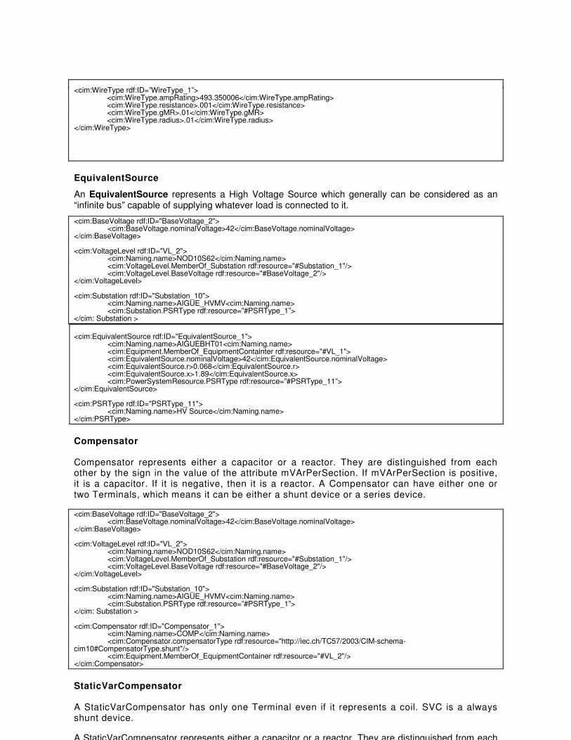
EquivalentSource
An EquivalentSource represents a High Voltage Source which generally can be considered as an “infinite bus” capable of supplying whatever load is connected to it.
<cim:BaseVoltage rdf:ID="BaseVoltage_2"> <cim:BaseVoltage.nominalVoltage>42</cim:BaseVoltage.nominalVoltage>
</cim:BaseVoltage> <cim:VoltageLevel rdf:ID="VL_2">
<cim:Naming.name>NOD10S62</cim:Naming.name> <cim:VoltageLevel.MemberOf_Substation rdf:resource="#Substation_1"/> <cim:VoltageLevel.BaseVoltage rdf:resource="#BaseVoltage_2"/>
</cim:VoltageLevel> <cim:Substation rdf:ID="Substation_10">
<cim:Naming.name>AIGUE_HVMV<cim:Naming.name> <cim:Substation.PSRType rdf:resource=”#PSRType_1”>
</cim: Substation >
<cim:EquivalentSource rdf:ID="EquivalentSource_1"> <cim:Naming.name>AIGUEBHT01<cim:Naming.name> <cim:Equipment.MemberOf_EquipmentContainter rdf:resource="#VL_1"> <cim:EquivalentSource.nominalVoltage>42</cim:EquivalentSource.nominalVoltage> <cim:EquivalentSource.r>0.068</cim:EquivalentSource.r>
<cim:EquivalentSource.x>1.89</cim:EquivalentSource.x> <cim:PowerSystemResource.PSRType rdf:resource=”#PSRType_11”>
</cim:EquivalentSource> <cim:PSRType rdf:ID="PSRType_11"> <cim:Naming.name>HV Source</cim:Naming.name> </cim:PSRType>
Compensator
Compensator represents either a capacitor or a reactor. They are distinguished from each other by the sign in the value of the attribute mVArPerSection. If mVArPerSection is positive, it is a capacitor. If it is negative, then it is a reactor. A Compensator can have either one or two Terminals, which means it can be either a shunt device or a series device.
<cim:BaseVoltage rdf:ID="BaseVoltage_2"> <cim:BaseVoltage.nominalVoltage>42</cim:BaseVoltage.nominalVoltage>
</cim:BaseVoltage> <cim:VoltageLevel rdf:ID="VL_2">
<cim:Naming.name>NOD10S62</cim:Naming.name> <cim:VoltageLevel.MemberOf_Substation rdf:resource="#Substation_1"/> <cim:VoltageLevel.BaseVoltage rdf:resource="#BaseVoltage_2"/>
</cim:VoltageLevel> <cim:Substation rdf:ID="Substation_10">
<cim:Naming.name>AIGUE_HVMV<cim:Naming.name> <cim:Substation.PSRType rdf:resource=”#PSRType_1”>
</cim: Substation > <cim:Compensator rdf:ID="Compensator_1"> <cim:Naming.name>COMP</cim:Naming.name> <cim:Compensator.compensatorType rdf:resource="http://iec.ch/TC57/2003/CIM-schema-cim10#CompensatorType.shunt"/> <cim:Equipment.MemberOf_EquipmentContainer rdf:resource="#VL_2"/> </cim:Compensator>
StaticVarCompensator
A StaticVarCompensator has only one Terminal even if it represents a coil. SVC is a always shunt device.
A StaticVarCompensator represents either a capacitor or a reactor. They are distinguished from each

other by the capacitiveRating (for capacitor) and inductiveRating (for reactor).
An example of a capacitor:
<cim:BaseVoltage rdf:ID="BaseVoltage_2"> <cim:BaseVoltage.nominalVoltage>42</cim:BaseVoltage.nominalVoltage>
</cim:BaseVoltage> <cim:VoltageLevel rdf:ID="VL_2">
<cim:Naming.name>NOD10S62</cim:Naming.name> <cim:VoltageLevel.MemberOf_Substation rdf:resource="#Substation_1"/> <cim:VoltageLevel.BaseVoltage rdf:resource="#BaseVoltage_2"/>
</cim:VoltageLevel> <cim:Substation rdf:ID="Substation_10">
<cim:Naming.name>AIGUE_HVMV<cim:Naming.name> <cim:Substation.PSRType rdf:resource=”#PSRType_1”>
</cim: Substation > <cim:StaticVarCompensator rdf:ID=" StaticVarCompensator _1"> <cim:Naming.name>AIGUEK0680<cim:Naming.name> <cim:Equipment.MemberOf_EquipmentContainter rdf:resource="#VL_2"> <cim:StaticVarCompensator.capacitiveRating> 900 </cim:StaticVarCompensator.capacitiveRating> </cim:StaticVarCompensator>
An example of a reactor:
<cim:BaseVoltage rdf:ID="BaseVoltage_2"> <cim:BaseVoltage.nominalVoltage>42</cim:BaseVoltage.nominalVoltage>
</cim:BaseVoltage> <cim:VoltageLevel rdf:ID="VL_2">
<cim:Naming.name>NOD10S62</cim:Naming.name> <cim:VoltageLevel.MemberOf_Substation rdf:resource="#Substation_1"/> <cim:VoltageLevel.BaseVoltage rdf:resource="#BaseVoltage_2"/>
</cim:VoltageLevel> <cim:Substation rdf:ID="Substation_10">
<cim:Naming.name>AIGUE_HVMV<cim:Naming.name> <cim:Substation.PSRType rdf:resource=”#PSRType_1”>
</cim: Substation > <cim:StaticVarCompensator rdf:ID=" StaticVarCompensator _1"> <cim:Naming.name>AIGUEK0680<cim:Naming.name> <cim:Equipment.MemberOf_EquipmentContainter rdf:resource="#VL_2"> <cim:StaticVarCompensator.inductiveRating> 900 </cim:StaticVarCompensator.inductiveRating> </cim:StaticVarCompensator>
EquivalentLoad
According to 61970-301 an EnergyConsumer is a generic user of energy - a point of consumption on the power system model. According to 61968-13, a MV customer is a CustomerMeter, a LV customer is an EquivalentLoad. An EquivalentLoad has the attribute customerCount having its value greater than one to indicate the number of customers attached. The voltage level is specified by a voltage level that contains this EquivalentLoad.
The abstract EnergyConsumer is used only when we do not know the detailed class (as for Switch, it is not recommended).
<cim:BaseVoltage rdf:ID="BaseVoltage_4"> <cim:BaseVoltage.nominalVoltage>0.22</cim:BaseVoltage.nominalVoltage>
</cim:BaseVoltage> <cim:VoltageLevel rdf:ID="VL_6">
<cim:Naming.name>NOD10S78</cim:Naming.name> <cim:VoltageLevel.MemberOf_Substation rdf:resource="#Substation_205"/> <cim:VoltageLevel.BaseVoltage rdf:resource="#BaseVoltage_4"/>
</cim:VoltageLevel> <cim:Substation rdf:ID="Substation_205">
<cim:Naming.name>AIGUE_MVLV<cim:Naming.name> <cim:Substation.PSRType rdf:resource=”#PSRType_3”>
</cim: Substation > <cim:PSRType rdf:ID="PSRType_3"> <cim:Naming.name>MV/LV Substation </cim:Naming.name> </cim:PSRType> <cim:EquivalentLoad rdf:ID="EquivalentLoad_1"> <cim:PowerSystemResource.MemberOf_EquipementContainer rdf:resource="#VL_4">

<cim:EnergyConsumer.pfixed>16.574152</cim:EnergyConsumer.pfixed> <cim:EnergyConsumer.qfixed>10.574152</cim:EnergyConsumer.qfixed> <cim:EnergyConsumer.powerFactor>0.905024</cim:EnergyConsumer.powerFactor> <cim:EnergyConsumer.customerCount>22</cim:EnergyConsumer.customerCount> </cim:EquivalentLoad> <cim:Terminal rdf:ID="Terminal_14">
<cim:Terminal.ConductingEquipment rdf:resource="#EnergyConsumer _1"/> <cim:Terminal.ConnectivityNode rdf:resource="#CN_2"/>
</cim:Terminal> <cim:ConnectivityNode rdf:ID=”CN_2”>
<cim:ConnectivityNode.MemberOf_EquipmentContainer rdf:resource=”#Substation_1”> </cim:ConnectivityNode>
Using CustomerMeter, GeneratingUnit and SynchronousMachine to model Distributed Energy Resource
For a Distributed Energy Resource (DER), we generate CustomerMeter, SynchronousMachine and GeneratingUnit to model it. When it consumes energy, we take data from CustomerMeter. When it produces energy, we take data from SynchronousMachine and GeneratingUnit.
A DER can have two different contracts: Energy Consumption and Energy Generation. A DER can be a Voltage regulator. For a DER we need to define its rated active Power and rated reactive Power. When P is positive, it is consuming energy. When P is negative, it acts as producing energy.
<cim:BaseVoltage rdf:ID="BaseVoltage_3"> <cim:BaseVoltage.nominalVoltage>20</cim:BaseVoltage.nominalVoltage>
</cim:BaseVoltage> <cim:VoltageLevel rdf:ID="VL_4">
<cim:Naming.name>NOD10S88</cim:Naming.name> <cim:VoltageLevel.MemberOf_Substation rdf:resource="#Substation_205"/> <cim:VoltageLevel.BaseVoltage rdf:resource="#BaseVoltage_3"/>
</cim:VoltageLevel> <cim:Substation rdf:ID="Substation_205">
<cim:Naming.name>AIGUE_MVLV<cim:Naming.name> <cim:Substation.PSRType rdf:resource=”#PSRType_3”>
</cim: Substation > <cim:CustomerMeter rdf:ID="CustomerMeter_1"> <cim:PowerSystemResource.MemberOf_EquipementContainer rdf:resource="#VL_4"> <cim:EnergyConsumer.pfixed>16.574152</cim:EnergyConsumer.pnom> <cim:EnergyConsumer.qfixed>10.574152</cim:EnergyConsumer.qnom> <cim:EnergyConsumer.powerFactor>0.905024</cim:EnergyConsumer.powerFactor> </cim:CustomerMeter> <cim:GeneratingUnit rdf:ID="GU_1">
<cim:Naming.name>NOD09S61_GU</cim:Naming.name> <cim:Equipment.MemberOf_EquipmentContainer rdf:resource="#VL_4"/> <cim:GeneratingUnit.initialMW>5.5</cim:GeneratingUnit.initialMW>
</cim:GeneratingUnit> <cim:SynchronousMachine rdf:ID="SM_1">
<cim:Naming.name>NOD02S71_SM</cim:Naming.name> <cim:Equipment.MemberOf_EquipmentContainer rdf:resource="#VL_4"/> <cim:SynchronousMachine.baseMVAr>2.2</cim:SynchronousMachine.baseMVAr> <cim:SynchronousMachine.MemberOf_GeneratingUnit rdf:resource="#GU_1"/>
</cim:SynchronousMachine> <cim:Terminal rdf:ID="Terminal_15">
<cim:Terminal.ConductingEquipment rdf:resource="#CustomerMeter_1"/> <cim:Terminal.ConnectivityNode rdf:resource="#CN_4"/>
</cim:Terminal> <cim:Terminal rdf:ID="Terminal_16">
<cim:Naming.name> NOD09S61_GU_T</cim:Naming.name> <cim:Terminal.ConductingEquipment rdf:resource="#GU_1 "/> <cim:Terminal.ConnectivityNode rdf:resource="#CN_4"/>
</cim:Terminal> <cim:Terminal rdf:ID="Terminal_17">
<cim:Naming.name>NOD02S71_SM_T</cim:Naming.name> <cim:Terminal.ConductingEquipment rdf:resource="#SM_1"/> <cim:Terminal.ConnectivityNode rdf:resource="#CN_4"/>
</cim:Terminal> <cim:ConnectivityNode rdf:ID=”CN_4”>
<cim: ConnectivityNode.MemberOf_EquipmentContainer rdf:resource=”#Substation_205”> </cim:ConnectivityNode>

GeneratingUnit
In most distribution networks, embedded generation is not intended to supply all load and can only operate while there is also a transmission source of supply. Thus embedded generators should be modeled as generators and not as an equivalent source . The output of an embedded generator may be specified by a curve and it may be specified as a P,Q schedule or a P,V schedule3.
In CPSM, these curves do not exist. There are the GrossToNetMWCurve which defines net power and gross power of the group and the MVArCapabilityCurve that defines Qmin and Qmax.
Note that in the case of a P,Q generator it is also acceptable to model it simply as a negative load, Connectivity Nodes and Terminals.
Connectivity Nodes and Terminal classes of the CIM topological model are used to describe the connectivity model. GeneratingUnit.initalMW is used to represent normal Active power (P).
<cim:BaseVoltage rdf:ID="BaseVoltage_1"> <cim:BaseVoltage.nominalVoltage>63</cim:BaseVoltage.nominalVoltage>
</cim:BaseVoltage> <cim:VoltageLevel rdf:ID="VL_1">
<cim:Naming.name>NOD10S61</cim:Naming.name> <cim:VoltageLevel.MemberOf_Substation rdf:resource="#Substation_1"/> <cim:VoltageLevel.BaseVoltage rdf:resource="#BaseVoltage_1"/>
</cim:VoltageLevel> <cim:Substation rdf:ID="Substation_1">
<cim:Naming.name>AIGUE_HVMV<cim:Naming.name> <cim:Substation.PSRType rdf:resource=”#PSRType_1”>
</cim: Substation > <cim:GeneratingUnit rdf:ID="GU_5">
<cim:Naming.name>NOD09S05_GU</cim:Naming.name> <cim:Equipment.MemberOf_EquipmentContainer rdf:resource="#VL_1"/> <cim:GeneratingUnit.initialMW>5.5</cim:GeneratingUnit.initialMW>
</cim:GeneratingUnit>
SynchronousMachine
SynchronousMachine.baseMVAr is used to represent reactive power (Q).
<cim:BaseVoltage rdf:ID="BaseVoltage_1"> <cim:BaseVoltage.nominalVoltage>63</cim:BaseVoltage.nominalVoltage>
</cim:BaseVoltage> <cim:VoltageLevel rdf:ID="VL_1">
<cim:Naming.name>NOD10S61</cim:Naming.name> <cim:VoltageLevel.MemberOf_Substation rdf:resource="#Substation_1"/> <cim:VoltageLevel.BaseVoltage rdf:resource="#BaseVoltage_1"/>
</cim:VoltageLevel> <cim:Substation rdf:ID="Substation_1">
<cim:Naming.name>AIGUE_HVMV<cim:Naming.name> <cim:Substation.PSRType rdf:resource=”#PSRType_1”>
</cim: Substation > <cim:SynchronousMachine rdf:ID="SM_1">
<cim:Naming.name>NOD02S71_SM</cim:Naming.name> <cim:Equipment.MemberOf_EquipmentContainer rdf:resource="#VL_1"/> <cim:SynchronousMachine.baseMVAr>2.2</cim:SynchronousMachine.baseMVAr> <cim:SynchronousMachine.MemberOf_GeneratingUnit rdf:resource="#GU_5"/>
</cim:SynchronousMachine>
HostControlArea
This class is not mandatory in 61968-13 (CDPSM) profile. We list it here since it is used in CPSM profile hierarchy.
<cim:HostControlArea rdf:ID="HCA_1"> <cim:Naming.name>HostControlArea_1</cim:Naming.name>
</cim:HostControlArea>
SubControlArea
——————— 3 A minimum set of data is required for an embedded generator and it is not necessary to have to support all the
61970-301 data for generators

This class is not mandatory in 61968-13 (CDPSM) profile. We list it here since it is used in CPSM profile hierarchy.
<cim:SubControlArea rdf:ID=”SCA_1"> <cim:Naming.name>07</cim:Naming.name> <cim:SubControlArea.HostControlArea rdf:resource="#HCA_1 "/>
</cim:SubControlArea>
Adequation between Part 13 (CDPSM) and Part 61968-4
In 61968 part 4 (Records and Asset Management), NetworkDataSet Message Type is defined. In order to proove that the standard is consistent and that the semantic is shared whatever XML support used (RDF, XSD), the following table highlights differences between CDPSM profile defined in part 13, and Cim elements used in NetworkDataSet Message Type. A comment is given when necessary. It has to be mentioned that 61968-13 relies on CPSM profile, as a consequence 61970-301 is used, thus PowerSytemResource is principally the base class which is used. On the other end, 61968-4, and NetworkDataSet message type, relied on all CIM classes, and extensions made in 61968-11, thus Asset class is also used as a base class.
The message type NetworkDataSet.xsd is based on CIM version 10 revision 7.
Remark : In order to be concise, if the same set of elements is found in the NetworkDataSet message type, we have used a global name to refer to it. For instance : TerminalSubSet.
The Message is composed of two blocks :
MessageHeader MessagePayload
CIM elements in NetworkDataSet Header
Verb
Noun
Revision
TimeDate
Source
SourcePathName
CIM elements in NetworkDataSet Payload Hierarchy level 0
Comment if it exist in CDPSM
<NetworkDataSet>
NameSubSet
aliasName
description
name
pathname
mrid
EndNameSubSet
collectionType
collectionQuantity
currentStatus
statusDate
<Equipement>
NameSubSet
Substation Yes
PSRType Yes
VoltageLevel Yes
Measurement Yes
Organisation Not used in CDPSM
Location Yes (Optional)
Structure Not used in CDPSM
UGStructure Not used in CDPSM
Manhole Not used in CDPSM
Pole Not used in CDPSM
Asset Not used in CDPSM
<Equipement\>
Ground Not used in CDPSM
AssetCatalogue Not Used in CDPSM
ConductingEquipment Yes
PowerTransformer Yes

EquivalentSource Yes
EnergyConsumer Yes
Switch Yes
Fuse Yes
Disconnector Yes
LoadBreakSwitch Yes
GroundDisconnector Yes
Jumper Yes
Breaker Yes
DCLineSegment Yes
ACLineSegment Yes
BusbarSection Yes
Junction Yes
EquivalentLoad Yes
InductionMotorLoad No
CustomerMeter Yes
SynchronousMachine Yes
StaticVarCompensator Yes
Compensator Yes
Based on the previous table, it can be said that 61968-13 is, at the present time, a subset of 61968-4, as it doesn’t include any asset related class.
Adequation between CDPSM and CPSM
Annex G compares CDPSM and CPSM through some CIM-XML-RDF files examples.

Annex A (Informative) CIM XML Document from Langdale
Electric utilities use power system models for a number of different purposes. For example, simulations of power systems are necessary for planning and security analysis. An operational power system model can consist of thousands of classes of information. In addition to using these models in-house, utilities need to exchange system modelling information, both in planning, and for operational purposes, e.g., for coordinating transmission and ensuring reliable operations. However, individual utilities use different software for these purposes, and as a result the system models are stored in different formats, making the exchange of these models difficult.
In order to support the exchange of power system models, utilities needed to agree on common definitions of power system entities and relationships. To support this, the Electric Power Research Institute (EPRI) a non-profit energy research consortium, developed a Common Information Model (CIM) [CIM]. The CIM specifies common semantics for power system resources, their attributes, and relationships. In addition, to further support the ability to electronically exchange CIM models, the power industry has developed CIM/XML, a language for expressing CIM models in XML. CIM/XML is an RDF application, using RDF and RDF Schema to organize its XML structures. The North American Electric Reliability Council (NERC) (an industry-supported organization formed to promote the reliability of electricity delivery in North America) has adopted CIM/XML as the standard for exchanging models between power transmission system operators. The CIM/XML format is also going through an IEC international standardization process. An excellent discussion of CIM/XML can be found in [DWZ01]. [NB: This power industry CIM should not be confused with the CIM developed by the Distributed Management Task Force for representing management information for distributed software, network, and enterprise environments. The DMTF CIM also has an XML representation, but does not currently use RDF, although independent research is underway in that direction.]
The CIM can represent all of the major objects of an electric utility as object classes and attributes, as well as their relationships. CIM uses these object classes and attributes to support the integration of independently developed applications between vendor specific EMS systems, or between an EMS system and other systems that are concerned with different aspects of power system operations, such as generation or distribution management.
The CIM is specified as a set of class diagrams using the Unified Modeling Language (UML). The base class of the CIM is the PowerSystemResource class, with other more specialized classes such as Substation, Switch, and Breaker being defined as subclasses. CIM/XML represents the CIM as an RDF Schema vocabulary, and uses RDF/XML as the language for exchanging specific system models. Example 1 shows examples of CIM/XML class and property definitions:
Example 1: Examples of CIM/XML Class and Property Definitions <rdfs:Class rdf:ID="PowerSystemResource">
<rdfs:label xml:lang="en">PowerSystemResource</rdfs:label>
<rdfs:comment>"A power system component that can be either an
individual element such as a switch or a set of elements

such as a substation. PowerSystemResources that are sets
could be members of other sets. For example a Switch is a
member of a Substation and a Substation could be a member
of a division of a Company"</rdfs:comment>
</rdfs:Class>
<rdfs:Class rdf:ID="Breaker">
<rdfs:label xml:lang="en">Breaker</rdfs:label>
<rdfs:subClassOf rdf:resource="#Switch" />
<rdfs:comment>"A mechanical switching device capable of making,
carrying, and breaking currents under normal circuit conditions
and also making, carrying for a specified time, and breaking
currents under specified abnormal circuit conditions e.g. those
of short circuit. The typeName is the type of breaker, e.g.,
oil, air blast, vacuum, SF6."</rdfs:comment>
</rdfs:Class>
<rdf:Property rdf:ID="Breaker.ampRating">
<rdfs:label xml:lang="en">ampRating</rdfs:label>
<rdfs:domain rdf:resource="#Breaker" />
<rdfs:range rdf:resource="#CurrentFlow" />
<rdfs:comment>"Fault interrupting rating in amperes"</rdfs:comment>
</rdf:Property>
CIM/XML uses only a subset of the complete RDF/XML syntax, in order to simplify expressing the models. In addition, CIM/XML implements some extensions to the RDF Schema vocabulary. These extensions support the description of inverse roles and multiplicity (cardinality) constraints describing how many instances of a given property are allowed for a given resource (allowable values for a multiplicity declaration are zero-or-one, exactly-one, zero-or-more, one-or-more). The properties in Example 2 illustrate these extensions (which are identified by a cims: QName prefix):
Example 2: Some CIM/XML Extensions of RDF Schema <rdf:Property rdf:ID="Breaker.OperatedBy">
<rdfs:label xml:lang="en">OperatedBy</rdfs:label>
<rdfs:domain rdf:resource="#Breaker" />
<rdfs:range rdf:resource="#ProtectionEquipment" />
<cims:inverseRoleName rdf:resource="#ProtectionEquipment.Operates"
/>
<cims:multiplicity rdf:resource="http://www.cim-
logic.com/schema/990530#M:0..n" />
<rdfs:comment>"Circuit breakers may be operated by
protection relays."</rdfs:comment>
</rdf:Property>
<rdf:Property rdf:ID="ProtectionEquipment.Operates">
<rdfs:label xml:lang="en">Operates</rdfs:label>
<rdfs:domain rdf:resource="#ProtectionEquipment" />
<rdfs:range rdf:resource="#Breaker" />
<cims:inverseRoleName rdf:resource="#Breaker.OperatedBy" />
<cims:multiplicity rdf:resource="http://www.cim-
logic.com/schema/990530#M:0..n" />
<rdfs:comment>"Circuit breakers may be operated by
protection relays."</rdfs:comment>
</rdf:Property>
EPRI has conducted successful interoperability tests using CIM/XML to exchange real-life, large-scale models (involving, in the case of one test, data describing over 2000 substations) between a variety of vendor products, and validating that these models would be correctly interpreted by typical utility applications. Although the CIM

was originally intended for EMS systems, it is also being extended to support power distribution and other applications as well.
The Object Management Group has adopted an object interface standard to access CIM power system models called the Data Access Facility [DAF]. Like the CIM/XML language, the DAF is based on the RDF model and shares the same CIM schema. However, while CIM/XML enables a model to be exchanged as a document, DAF enables an application to access the model as a set of objects.
CIM/XML illustrates the useful role RDF can play in supporting XML-based exchange of information that is naturally expressed as entity-relationship or object-oriented classes, attributes, and relationships (even when that information will not necessarily be Web-accessible). In these cases, RDF provides a basic structure for the XML in support of identifying objects, and using them in structured relationships. This connection is illustrated by a number of applications using RDF/XML for information interchange, as well as a number of projects investigating linkages between RDF (or ontology languages such as OWL) and UML (and its XML representations). CIM/XML's need to extend RDF Schema to support cardinality constraints and inverse relationships also illustrates the kinds of requirements that have led to the development of more powerful RDF-based schema/ontology languages such as DAML+OIL and OWL. Such languages may be appropriate in supporting many similar modelling applications in the future.
Finally, CIM/XML also illustrates an important fact for those looking for additional examples of "RDF in the Field": sometimes languages are described as "XML" languages, or systems are described as using "XML", and the "XML" they are actually using is RDF/XML, i.e., they are RDF applications. Sometimes it is necessary to go fairly far into the description of the language or system in order to find this out (in some examples that have been found, RDF is never explicitly mentioned at all, but sample data clearly shows it is RDF/XML). Moreover, in applications such as CIM/XML, the RDF that is created will not be readily found on the Web, since it is intended for information exchange between software components rather than for general access (although future scenarios could be imagined in which more of this type of RDF would become Web-accessible).

Annex B (Informative) Comparison from CIM RDF and CIM XSD (ISO ITC Working Group Architecture)
Categories CIM/RDF CIM/XSD
Technologies RDF, RDF(S), XSD and XML XSD and XML
Semantics A semantic model for CIM modelled by RDF(S) and namespace extension “cims”. It is a schema for describing the CIM semantics.
It is a schema for describing format and structure of the model for defining messages. It is an XSD representation of CIM with embedded semantic information.
Data Types and Instances
String Wide range of data types
Format and Structure
Additional specification needs to be provided on top of RDF. WG13 has produced two documents, 61970-501 and 503 that specify how to use RDF Schema for power system model transfers.
XSD structure
Technology Development Status
RDF(S) is a W3C recommendation but cims namespace is a WG13 extension
XML Schema is a W3C recommendation
Technology acceptance and support
• Continues to be modified and developed
• Requires time for more people to appreciate it
• Limited supporting tools
• Has evolved
• should be replaced with OWL
• Wide acceptance
• Ease of use
• Many supporting and companion standards such as XSLT
• Lots of supporting tools
Base File RDF representation of CIM UML model.
XSD representation of CIM UML model.
CIM Classes • Represented as an element with the CIM class name and identified by rdf:ID
• Defined by complexType with an identifier.
Defined by complexType with mrid attribute as a unique identifier
CIM Attributes Represented as an element with the CIM attribute name.
Defined as local elements.
CIM Relationships
Represented as an element with a reference pointing to the related instance.
Flexible structure. Can use: • Containment • Reference • Reference with key/keyref
Message Schema Generation
Not available for a direct XML representation of RDF schema; Manually identify classes and attributes for the message schema.
Messages are modelled using UML and then message schemas are automatically generated based on user selected message configuration options.

Message Schema structure
• Fixed and flat structure without conforming schemas
• Once the message schema is defined, there is no programmatic connection between the message and CIM/RDF base file. The message schema is defined using CIM but can not be validated afterwards. Changes made to the schema that deviate from CIM will not make it invalid.
• Certain CIM definitions are not carried into the schema, and definitions are repeated in every schema.
•
Options are provided for message structure. Individual message schemas are based on the base file and therefore always conform to CIM semantics, and they can easily be made backward compatible.
Schema Level Validation
• A specialized CIM Validator is provided, but is designed for Network Model Data exchange.
• Data type checking is not included.
• The referenced relationship cannot be validated through XSD validation either.
The message schema provides the schema level validation. Relationships can be checked either by the containment or the key/keyref.
Required Element Validation
• Validation is by convention. By selecting the class and attribute profile to be included in the schema (examples are CPSM and this document).
• Schema will need to change as new attributes for the schema are needed even from existing CIM classes.
All CIM attributes are included in the schema design as optional elements. Required elements are checked by using XSLT.
Business Rule Validation
Not available. Business rules can be defined using XSLT.
Annex C (Informative) Key Discussion points on CIM RDF and CIM XSD (ISO ITC Working Group Architecture)

1. RDF was chosen when XSD was immature and not yet a standard. RDF proved to be the correct choice for electric network model exchange because:
a. Electric network models are very complex and require a flexible and object oriented way to represent network connectivity;
b. The “flat” nature of CIM/RDF XML instance data helps reduce the amount of data to represent and process large electric network models;
c. Several application vendors have adopted CIM/RDF for network model exchange.
d. CIM/RDF for Full Network Model that includes both the physical and dynamic (market) components of a network model is a natural extension of CIM/RDF.
2. RDF may prove useful for messages very similar in nature to network models (large
and complex and require very efficient structure to minimize message size etc.), such as used for inter-application data exchange in a homogeneous operating environment, but RDF is not the right choice for a vast majority of loosely-coupled business messages such as Bids, Interchange Schedules, Outages, and Work etc., that are exchanged between systems or enterprises. XSD, on the other hand, is designed for a well-structured representation of business data in general, which is why most other industry standards for common data exchange use XSD, not RDF.
3. RDF was designed primarily for semantic representation, not data exchange, but
industry standards have continued to evolve beyond RDF. OWL Web Ontology Language provides a more robust structure for representing complex and object-oriented data. OWL builds upon RDF specification and will be the language of choice for representing semantics. OWL was only recently enacted as a standard and there are not many implementations as of yet.
4. XSD is used for message definition because of the following advantages:
• Attributes of all classes are now represented in messages (previous messages used XML QName pointers to classes not included in the message)
• CIM classes are logically represented in XML Schema as they are defined in UML
• CIM associations are represented using functionality provided by XML Schema
• Data integrity is assured within a message instance to ensure content is meaningful to both sender and receiver
• Strong typing is provided to XML data types whenever possible to ensure that content is represented as intended by the CIM
• Reliance on programmatic logic in message adaptors to determine the meaning of a message, i.e., discovering class associations, is reduced
• The mapping of messages to business vocabularies is simplified
• Messages adhere to generally applied XML Schema design methodologies
Annex D (Informative) Conclusions and recommendations (ISO ITC Working Group Architecture)
This paper defines an approach and includes the necessary guidelines for leveraging the CIM/CME to produce XSD representations. The following recommendations are being proposed:
1. When defining infrastructures, creating interfaces and performing integrations the CIM/CME should be leveraged as a standard ontology model. It provides the basis for reducing dissonance and defining data unambiguously. It provides mechanisms for extensions and is an adequate platform independent model for the utilities domain.
2. Apply model-based principles by using the CIM and a consistent approach for forward
engineering to XSD or RDF depending on the data requirements. This will improve interoperability, reliability and reduce the cost of integration.
3. As CIM extensions become necessary submit them to the standards body for adoption
and ratification. It is also recommended that the ISO/RTO share the extensions (prior to submission) as they are defined to reduce overlaps and improve consistency of the CIM/CME.
4. Both RDF and XSD based formats should be used when implementing CIM based
architectures – RDF should be utilized for network model exchanges and XSD for all other use-cases.
5. Closely follow emerging standards (i.e. OWL)

Annex E (informative) Example of a European Distribution Network Described through CIM RDF
A Distribution Network
An example of a MV European distribution network is presented as follows.
EC
ACLineSegment (Wires)
Terminal (Core)
ConnectivityNode (Topology)
LoadBreakSwitch (Wires)
Breaker (Wires)
PowerTransformer
2 Windings (Wires)
EnergyConsumer (Wires)
Substation (Core)
Bay (Core)
Line (Wires)
S EquivalentSource (Wires)
C Compensator (Wires)

S
C
HV Source "_01"
"_01""_02"
CN "_01"
"_03""_04"CN "_02"
CN "_036"
Busbar "_02" CN "_019"TW "_08", "_09"
Breaker "_07"
HV/MVSubstation
"_01"
MV/LV
Substation"_205"
Breaker "_093"
Transfo "_01"
TW "_01"
TW "_02"
"_06""_07"
Breaker "_2300"
CN "_09"TW "_14", and "_15"
ECMV Network
LoadBreakSwitch "_01"
"_18""_19"
CN "_12",TW "_20", "_21"
EnergyConsumer"_205"
CN "_033"TW "_16" and "_17"
Line"_0216"
CN "_31"
"_28", "_29"
CN "_16"
"_26"
CN "_15"
Breaker "_Y0001"
LoadBreakSwitch"_02"
Transfo "_02"TW_03, TW_04
Busbar "_05"
Vo
lta
ge
Le
ve
l "_
01
"V
olta
ge
Le
ve
l "_
03
"V
olta
ge
Le
ve
l "_
05
"
"_10", "_11"
"_08", "_09"
Corresponding CIM RDF
<cim:BaseVoltage rdf:ID="BaseVoltage_01"> <cim:BaseVoltage.nominalVoltage>42</cim:BaseVoltage.nominalVoltage>
</cim:BaseVoltage> <cim:VoltageLevel rdf:ID="VL_01">
<cim:Naming.name>VL_42_1</cim:Naming.name> <cim:VoltageLevel.MemberOf_Substation rdf:resource="#Substation_01"/> <cim:VoltageLevel.BaseVoltage rdf:resource="#BaseVoltage_01"/>
</cim:VoltageLevel> <cim:VoltageLevel rdf:ID="VL_02">
<cim:Naming.name>VL_42_2</cim:Naming.name> <cim:VoltageLevel.MemberOf_Substation rdf:resource="#Substation_01"/> <cim:VoltageLevel.BaseVoltage rdf:resource="#BaseVoltage_01"/>
</cim:VoltageLevel> <cim:BaseVoltage rdf:ID="BaseVoltage_02">
<cim:BaseVoltage.nominalVoltage>20</cim:BaseVoltage.nominalVoltage> </cim:BaseVoltage> <cim:VoltageLevel rdf:ID="VL_03">
<cim:Naming.name>VL_20_1</cim:Naming.name> <cim:VoltageLevel.MemberOf_Substation rdf:resource="#Substation_01"/> <cim:VoltageLevel.BaseVoltage rdf:resource="#BaseVoltage_02"/>
</cim:VoltageLevel> <cim:VoltageLevel rdf:ID="VL_04">
<cim:Naming.name>VL_20_2</cim:Naming.name> <cim:VoltageLevel.MemberOf_Substation rdf:resource="#Substation_01"/> <cim:VoltageLevel.BaseVoltage rdf:resource="#BaseVoltage_02"/>

</cim:VoltageLevel> <cim:BaseVoltage rdf:ID="BaseVoltage_03">
<cim:BaseVoltage.nominalVoltage>0.22</cim:BaseVoltage.nominalVoltage> </cim:BaseVoltage> <cim:VoltageLevel rdf:ID="VL_05">
<cim:Naming.name>VL_0.22_1</cim:Naming.name> <cim:VoltageLevel.MemberOf_Substation rdf:resource="#Substation_01"/> <cim:VoltageLevel.BaseVoltage rdf:resource="#BaseVoltage_02"/>
</cim:VoltageLevel> <cim:VoltageLevel rdf:ID="VL_06">
<cim:Naming.name>VL_0.22_2</cim:Naming.name> <cim:VoltageLevel.MemberOf_Substation rdf:resource="#Substation_205"/> <cim:VoltageLevel.BaseVoltage rdf:resource="#BaseVoltage_03"/>
</cim:VoltageLevel> <cim:Substation rdf:ID="Substation_01"> <cim:Naming.name>AIGUE_HVMV<cim:Naming.name>
<cim:PowerSystemResource.PSRType rdf:resource="#PSRType_1"> </cim:Substation> <cim:PSRType rdf:ID="PSRType_1"> <cim:Naming.name>HV/MV Substation</cim:Naming.name> </cim:PSRType> <cim:Location rdf:ID="Location_1"/>
<cim:Location.PowerSystemResource rdf:resource=”#Substation_01”> </cim:Location> <cim: CoordinatePair rdf:ID="CP1001”>
<cim:CoordinatePair.xPosition>763593</cim:CoordinatePair.xPosition> <cim:CoordinatePair.yPosition>172693</cim:CoordinatePair.yPosition> <cim:CoordinatePair.Location rdf:resource="#Location_1"/> </cim:CoordinatePair > <cim:EquivalentSource rdf:ID="EquivalentSource_01">
<cim:Naming.name>AIGUEBHT01<cim:Naming.name> <cim:Equipment.MemberOf_EquipmentContainter rdf:resource="#VL_01"> <cim:PowerSystemResource.PSRType rdf:resource="#PSRType_11">
<cim:EquivalentSource.nominalVoltage>90</cim:EquivalentSource.nominalVoltage> <cim:EquivalentSource.x>17.052631</cim:EquivalentSource.x> <cim:EquivalentSource.r>0</cim:EquivalentSource.r>
</cim:EquivalentSource> <cim:PSRType rdf:ID="PSRType_11"> <cim:Naming.name>HV Source</cim:Naming.name> </cim:PSRType> <cim:Location rdf:ID="Location_12"/> <cim:Location.PowerSystemResource rdf:resource="#EquivalentSource_01"> </cim:Location> <cim:CoordinatePair rdf:ID="CP1002">
<cim:CoordinatePair.xPosition>763603</cim:CoordinatePair.xPosition> <cim:CoordinatePair.yPosition>172703</cim:CoordinatePair.yPosition> <cim:CoordinatePair.Location rdf:resource="#Location_12"/>
</cim:CoordinatePair> <cim:Terminal rdf:ID="Terminal_01">
<cim:Terminal.ConductingEquipment rdf:resource="#EquivalentSource_01"/> <cim:Terminal.ConnectivityNode rdf:resource="#CN_01"/>
</cim:Terminal> <cim :ConnectivityNode rdf :ID=”CN_01”>
<cim:ConnectivityNode.MemberOf_EquipmentContainer rdf:resource=”#VL_01”> </cim:ConnectivityNode> <cim:Terminal rdf:ID="Terminal_02">
<cim:Terminal.ConductingEquipment rdf:resource="#Breaker_Y0001"/> <cim:Terminal.ConnectivityNode rdf:resource="#CN_01"/>
</cim:Terminal> <cim:Breaker rdf:ID="Breaker_Y0001">
<cim:Naming.name>AIGUEY0001_Breaker<cim:Naming.name> <cim:Switch.normalOpen>false</cim:Switch.normalOpen> <cim:Equipment.MemberOf_EquipmentContainer rdf:resource="#VL_01">
</cim:Breaker> <cim:Terminal rdf:ID="Terminal_03">
<cim:Terminal.ConductingEquipment rdf:resource="#Breaker_Y0001"/> <cim:Terminal.ConnectivityNode rdf:resource="#CN_02"/>
</cim:Terminal> <cim :ConnectivityNode rdf :ID=”CN_02”>
<cim:ConnectivityNode.MemberOf_EquipmentContainer rdf:resource=”#VL_01”> </cim:ConnectivityNode>

<cim:Terminal rdf:ID="Terminal_04">
<cim:Terminal.ConductingEquipment rdf:resource="#TW_01"/> <cim:Terminal.ConnectivityNode rdf:resource="#CN_02"/>
</cim:Terminal> <cim:PowerTransformer rdf:ID="Transfo_01"> <cim:Naming.name>AIGUEY0001<cim:Naming.name> <cim:Equipment.MemberOf_EquipmentContainter rdf:resource="#Substation_01"> </cim:PowerTransformer> <cim:Location rdf:ID="Location_7"> <cim:Location.PowerSystemResource rdf:resource="#Transfo_01"> </cim:Location> <cim:CoordinatePair rdf:ID=”CP1003”>
<cim:CoordinatePair.xPosition>763763</cim:CoordinatePair.xPosition> <cim:CoordinatePair.yPosition>172863</cim:CoordinatePair.yPosition>
<cim:CoordinatePair.Location rdf:resource="#Location_7"/> </cim:CoordinatePair> <cim:TransformerWinding rdf:ID="TW_01">
<cim:Naming.name>AIGUEY0001_TW1</cim:Naming.name> <cim:TransformerWinding.g>30.413794</cim:TransformerWinding.g> <cim:TransformerWinding.r>0</cim:TransformerWinding.r> <cim:TransformerWinding.ratedKV>42</cim:TransformerWinding.ratedKV> <cim:TransformerWinding.ratedMVA>20</cim:TransformerWinding.ratedMVA> <cim:TransformerWinding.shortTermMVA>22</cim:TransformerWinding.shortTermMVA> <cim:TransformerWinding.windingType rdf:resource="http://iec.ch/TC57/2003/CIM-schema-
cim10#WindingType.primary"/> <cim:TransformerWinding.x>0</cim:TransformerWinding.x> <cim:TransformerWinding.MemberOf_PowerTransformer rdf:resource="#Transfo_01"/> <cim:ConductingEquipment.BaseVoltage rdf:resource="#VL_01"/>
</cim:TransformerWinding> <cim:TransformerWinding rdf:ID="TW_02">
<cim:Naming.name>AIGUEY0001_TW2</cim:Naming.name> <cim:TransformerWinding.g>6.8965516</cim:TransformerWinding.g> <cim:TransformerWinding.r>0</cim:TransformerWinding.r> <cim:TransformerWinding.ratedKV>20</cim:TransformerWinding.ratedKV> <cim:TransformerWinding.ratedMVA>20</cim:TransformerWinding.ratedMVA> <cim:TransformerWinding.shortTermMVA>22</cim:TransformerWinding.shortTermMVA> <cim:TransformerWinding.windingType rdf:resource="http://iec.ch/TC57/2003/CIM-schema-
cim10#WindingType.secondary"/> <cim:TransformerWinding.x>0</cim:TransformerWinding.x> <cim:TransformerWinding.MemberOf_PowerTransformer rdf:resource="#Transfo_01"/> <cim:ConductingEquipment.BaseVoltage rdf:resource="#VL_02"/>
</cim:TransformerWinding> <cim:Terminal rdf:ID="Terminal_06">
<cim:Terminal.ConductingEquipment rdf:resource="#Tw_02"/> <cim:Terminal.ConnectivityNode rdf:resource="#CN_036"/>
</cim:Terminal> <cim :ConnectivityNode rdf :ID=”CN_036”>
<cim: ConnectivityNode.MemberOf_EquipmentContainer rdf:resource=”#VL_03”> </cim:ConnectivityNode> <cim:Terminal rdf:ID="Terminal_07">
<cim:Terminal.ConductingEquipment rdf:resource="#Breaker_2300"/> <cim:Terminal.ConnectivityNode rdf:resource="#CN_036"/>
</cim:Terminal>
<cim:Breaker rdf:ID="Breaker_2300"> <cim:Naming.name>AIGUEC2300_Breaker<cim:Naming.name> <cim:Switch.normalOpen>false</cim:Switch.normalOpen> <cim:Equipment.MemberOf_EquipmentContainer rdf:resource="#VL_03"> </cim:Breaker> <cim:Location rdf:ID="Location_5"> <cim:Location.PowerSystemResource rdf:resource="#Breaker_2300"> </cim:Location> <cim:CoordinatePair rdf:ID=”CP1004”>
<cim:CoordinatePair.xPosition>763693</cim:CoordinatePair.xPosition> <cim:CoordinatePair.yPosition>172793</cim:CoordinatePair.yPosition> <cim:CoordinatePair.Location rdf:resource="#Location_5"/>
</cim:CoordinatePair> <cim:Terminal rdf:ID="Terminal_08">
<cim:Terminal.ConductingEquipment rdf:resource="#Breaker_2300"/> <cim:Terminal.ConnectivityNode rdf:resource="#CN_019"/>
</cim:Terminal> <cim :ConnectivityNode rdf :ID=”CN_019”>
<cim: ConnectivityNode.MemberOf_EquipmentContainer rdf:resource=”#VL_03”> </cim:ConnectivityNode> <cim:Terminal rdf:ID="Terminal_09">

<cim:Terminal.ConductingEquipment rdf:resource="#Breaker_093"/> <cim:Terminal.ConnectivityNode rdf:resource="#CN_019"/>
</cim:Terminal> <cim:Terminal rdf:ID="Terminal_10">
<cim:Terminal.ConductingEquipment rdf:resource="#Busbar_02"/> <cim:Terminal.ConnectivityNode rdf:resource="#CN_019"/>
</cim:Terminal> <cim:BusbarSection rdf:ID="Busbar_02"> <cim:Naming.name>AIGUEB0002 <cim:Naming.name> <cim:Equipment.MemberOf_EquipmentContainter rdf:resource="#VL_03"> </cim:BusbarSection> <cim:Location rdf:ID="Location_6”>
<cim:Location.PowerSystemResource rdf:resource="#Busbar_02"> </cim:Location> <cim:CoordinatePair rdf:ID=”CP1005”>
<cim:CoordinatePair.xPosition>763623</cim:CoordinatePair.xPosition> <cim:CoordinatePair.yPosition>172723</cim:CoordinatePair.yPosition> <cim:CoordinatePair.Location rdf:resource="#Location_6"/>
</cim:CoordinatePair> <cim:Breaker rdf:ID="Breaker_093"> <cim:Naming.name>AIGUEC0093_Breaker<cim:Naming.name> <cim:Switch.normalOpen>false</cim:Switch.normalOpen> <cim:Equipment.MemberOf_EquipmentContainer rdf:resource="#VL_3"> </cim:Breaker> <cim:Terminal rdf:ID="Terminal_16">
<cim:Terminal.ConductingEquipment rdf:resource="#Breaker_093"/> <cim:Terminal.ConnectivityNode rdf:resource="#CN_033"/>
</cim:Terminal> <cim :ConnectivityNode rdf :ID=”CN_033”>
<cim: ConnectivityNode.MemberOf_EquipmentContainer rdf:resource=”#VL_3”> </cim:ConnectivityNode> <cim:Terminal rdf:ID="Terminal_17">
<cim:Terminal.ConductingEquipment rdf:resource="#SVC_2000"/> <cim:Terminal.ConnectivityNode rdf:resource="#CN_033"/>
</cim:Terminal> <cim:Compensator rdf:ID="Comp_2000">
<cim:Naming.name>AIGUEK2000<cim:Naming.name> <cim:Equipment.MemeberOf_EquipmentContainter rdf:resource="#VL_3"> <cim:PowerSystemResource.Location rdf:resource="#Location_42">
</cim:Compensator>
<cim:Location rdf:ID="Location_42"> <cim:Location.PowerSystemResource rdf:resource="#Comp_2000">
</cim:Location> <cim:CoordinatePair rdf:ID=”CP1006”>
<cim:CoordinatePair.xPosition>763753</cim:CoordinatePair.xPosition> <cim:CoordinatePair.yPosition>172853</cim:CoordinatePair.yPosition> <cim:CoordinatePair.Location rdf:resource="#Location_42"/>
</cim:CoordinatePair> <cim:Breaker rdf:ID="Breaker_07"> <cim:Naming.name>AIGUEC0093_Breaker<cim:Naming.name> <cim:Switch.normalOpen>false</cim:Switch.normalOpen> <cim:Equipment.MemberOf_EquipmentContainer rdf:resource="#VL_3">
<cim:PowerSystemResource.PSRType rdf:resource="#PSRType_5"> </cim:Breaker> <cim:Terminal rdf:ID="Terminal_11">
<cim:Terminal.ConductingEquipment rdf:resource="#Breaker_07"/> <cim:Terminal.ConnectivityNode rdf:resource="#CN_019"/>
</cim:Terminal> <cim:Location rdf:ID="Location_93">
<cim:Location.PowerSystemResource rdf:resource="#Breaker_07"> </cim:Location> <cim:CoordinatePair rdf:ID=”CP1007”>
<cim:CoordinatePair.xPosition>763590</cim:CoordinatePair.xPosition> <cim:CoordinatePair.yPosition>172691.8</cim:CoordinatePair.yPosition> <cim:CoordinatePair.Location rdf:resource="#Location_93"/>
</cim:CoordinatePair> <cim:PSRType rdf:ID="PSRType_5">
<cim:Naming.name>OUTGOING FEEDER</cim:Naming.name> </cim:PSRType> <cim:Terminal rdf:ID="Terminal_14">
<cim:Terminal.ConductingEquipment rdf:resource="#Breaker_07"/> <cim:Terminal.ConnectivityNode rdf:resource="#CN_09"/>

</cim:Terminal> <cim :ConnectivityNode rdf :ID=”CN_09”>
<cim: ConnectivityNode.MemberOf_EquipmentContainer rdf:resource=”#VL_3”> </cim:ConnectivityNode> <cim:Terminal rdf:ID="Terminal_15">
<cim:Terminal.ConductingEquipment rdf:resource="#ACLS_0216_1"/> <cim:Terminal.ConnectivityNode rdf:resource="#CN_09"/>
</cim:Terminal>
<cim:Line rdf:ID="Line_0216"> <cim:Naming.description>AIGUE0216</cim:Naming.description> <cim:PowerSystemResource.Location rdf:resource="#Location_85">
</cim:Line> <cim:Location rdf:ID="Location_85">
<cim:Location.PowerSystemResource rdf:resource="#Line_0216"> </cim:Location>
<cim:CoordinatePair rdf:ID=”CP2000>
<cim:CoordinatePair.xPosition>763577.7</cim:CoordinatePair.xPosition> <cim:CoordinatePair.yPosition>172692.7</cim:CoordinatePair.yPosition> <cim:CoordinatePair.Location rdf:resource="#Location_85"/>
</cim:CoordinatePair> <cim:CoordinatePair rdf:ID=”CP1008”>
<cim:CoordinatePair.xPosition>763542.3</cim:CoordinatePair.xPosition> <cim:CoordinatePair.yPosition>172718.7</cim:CoordinatePair.yPosition> <cim:CoordinatePair.Location rdf:resource="#Location_85"/>
</cim:CoordinatePair> <cim:CoordinatePair rdf:ID=”CP1009”>
<cim:CoordinatePair.xPosition>763608.4</cim:CoordinatePair.xPosition> <cim:CoordinatePair.yPosition>172802.7</cim:CoordinatePair.yPosition> <cim:CoordinatePair.Location rdf:resource="#Location_85"/>
</cim:CoordinatePair> <cim:ACLineSegment rdf:ID="ACLS_0216_1"> <cim:ACLineSegment.MemberOf_Line rdf:resource="#Line_0216"/> <cim:ConductingEquipment.BaseVoltage rdf:resource="#BaseVoltage02”/>
<cim:Conductor.length>566</cim:Conductor.length> <cim:ConductorType rdf:resource=”ConductorType_1”> <cim:ACLineSegment.r>0.2</cim:ACLineSegment.r> <cim:ACLineSegment.x>0.1</cim:ACLineSegment.x> <cim:ACLineSegment.b0ch>449</cim:ACLineSegment.g0ch> </cim:ACLineSegment> <cim:ConductorType rdf:ID=”ConductorType_1”/> <cim:WireArrangement rdf:ID=”WireArrangement_1”> <cim: WireArrangement.WireType rdf:resource=”#WireType_1”> <cim: WireArrangement.ConductorType rdf:resource=”#ConductorType_1”> </cim:WireArrangement> <cim:WireType rdf:ID=”WireType_1”>
<cim:WireType.ampRating>258.225006</cim:WireType.ampRating> </cim:WireType> <cim:Substation rdf:ID="Substation_205"> <cim:Naming.name>30189P0205<cim:Naming.name>
<cim:PowerSystemResource.Location rdf:resource="#Location_2"> <cim:PowerSystemResource.PSRType rdf:resource="#PSRType_2">
</cim:Substation> <cim:PSRType rdf:ID="PSRType_2"> <cim:Naming.name>MV/LV Substation</cim:Naming.name> </cim:PSRType> <cim:Location rdf:ID="Location_2">
<cim:Location.PowerSystemResource rdf:resource="#Substation_205"> </cim:Location> <cim:CoordinatePair rdf:ID=”CP1010”>
<cim:CoordinatePair.xPosition>763682.7</cim:CoordinatePair.xPosition> <cim:CoordinatePair.yPosition>173102</cim:CoordinatePair.yPosition> <cim:CoordinatePair.Location rdf:resource="#Location_2"/>
</cim:CoordinatePair> <cim:Terminal rdf:ID="Terminal_18">
<cim:Terminal.ConductingEquipment rdf:resource="#ACLS_0216_1"/> <cim:Terminal.ConnectivityNode rdf:resource="#CN_031"/>
</cim:Terminal> <cim :ConnectivityNode rdf :ID=”CN_031”>
<cim: ConnectivityNode.MemberOf_EquipmentContainer rdf:resource=”#VL_05”> </cim:ConnectivityNode> <cim:Terminal rdf:ID="Terminal_19">

<cim:Terminal.ConductingEquipment rdf:resource="#LoadBreakSwitch_01"/> <cim:Terminal.ConnectivityNode rdf:resource="#CN_031"/>
</cim:Terminal> <cim:LoadBreakSwitch rdf:ID="LoadBreakSwitch_01"> <cim:Naming.name>30189P0205_LBS1<cim:Naming.name>
<cim:Switch.normalOpen>false</cim:Switch.normalOpen> <cim:Equipment.MemberOf_EquipmentContainer rdf:resource="#VL_05"> </cim:LoadBreakSwitch> <cim :ConnectivityNode rdf :ID=”CN_012”>
<cim: ConnectivityNode.MemberOf_EquipmentContainer rdf:resource=”#VL_05”> </cim:ConnectivityNode> <cim:Terminal rdf:ID="Terminal_20">
<cim:Terminal.ConductingEquipment rdf:resource="#LoadBreakSwitch_01"/> <cim:Terminal.ConnectivityNode rdf:resource="#CN_012"/>
</cim:Terminal> <cim:Terminal rdf:ID="Terminal_21">
<cim:Terminal.ConductingEquipment rdf:resource="#TW_03"/> <cim:Terminal.ConnectivityNode rdf:resource="#CN_012"/>
</cim:Terminal> <cim:Terminal rdf:ID="Terminal_31">
<cim:Terminal.ConductingEquipment rdf:resource="#BusbarSection_05"/> <cim:Terminal.ConnectivityNode rdf:resource="#CN_012"/>
</cim:Terminal> <cim:Terminal rdf:ID="Terminal_32">
<cim:Terminal.ConductingEquipment rdf:resource="#LoadBreakSwitch_02"/> <cim:Terminal.ConnectivityNode rdf:resource="#CN_012"/>
</cim:Terminal> <cim:BusbarSection rdf:ID="Busbar_05">
<cim:Naming.name>30189P0205_Busbar_01<cim:Naming.name> <cim:Equipment.MemberOf_EquipmentContainter rdf:resource="#VL_05">
</cim:BusbarSection>
<cim:PowerTransformer rdf:ID="Transfo_02"> <cim:Naming.name>30189P0205_Transfo_01<cim:Naming.name> <cim:Equipment.MemberOf_EquipmentContainter rdf:resource="#Substation_205"> </cim:PowerTransformer>
<cim:TransformerWinding rdf:ID="TW_03"> <cim:TransformerWinding.MemberOf_PowerTransformer rdf:resource="#Transfo_02"> <cim:TransformerWinding.ratedKV>20</cim:TransformerWinding.ratedKV>
<cim:ConductingEquipment.BaseVoltage rdf:resource="#BaseVoltage_02"/> </cim:TransformerWinding> <cim:TransformerWinding rdf:ID="TW_04"> <cim:TransformerWinding.MemberOf_PowerTransformer rdf:resource="#Transfo_02">
<cim:ConductingEquipment.BaseVoltage rdf:resource="#BaseVoltage_03"/> <cim:TransformerWinding.ratedKV>0.22</cim:TransformerWinding.ratedKV>
</cim:TransformerWinding> <cim:Terminal rdf:ID="Terminal_28">
<cim:Terminal.ConductingEquipment rdf:resource="#TW_04"/> <cim:Terminal.ConnectivityNode rdf:resource="#CN_016"/>
</cim:Terminal> <cim :ConnectivityNode rdf :ID=”CN_016”>
<cim: ConnectivityNode.MemberOf_EquipmentContainer rdf:resource=”#VL_05”> </cim:ConnectivityNode> <cim:Terminal rdf:ID="Terminal_29">
<cim:Terminal.ConductingEquipment rdf:resource="#EC_205"/> <cim:Terminal.ConnectivityNode rdf:resource="#CN_016"/>
</cim:Terminal> <cim:EquivalentLoad rdf:ID="EC_205"> <cim:PowerSystemResource.MemberOf_EquipementContainer rdf:resource="#VL_05"> <cim:EnergyConsumer.pnom>0.081</cim:EnergyConsumer.pnom>
<cim:EnergyConsumer.qnom>0,002693</cim:EnergyConsumer.qnom> <cim:EnergyConsumer.powerFactor>0.967823</cim:EnergyConsumer.powerFactor> <cim:EnergyConsumer.customerCount>173</cim:EnergyConsumer.customerCount> </cim:EquivalentLoad > <cim:LoadBreakSwitch rdf:ID="LoadBreakSwitch_2">
<cim:Naming.name>30189P0205_LBS2<cim:Naming.name> <cim:Switch.normalOpen>false</cim:Switch.normalOpen> <cim:Equipment.MemberOf_EquipmentContainer rdf:resource="#VL_05">
</cim:LoadBreakSwitch>
<cim:Terminal rdf:ID="Terminal_26"> <cim:Terminal.ConductingEquipment rdf:resource="#LoadBreakSwitch_2"/> <cim:Terminal.ConnectivityNode rdf:resource="#CN_15"/>
</cim:Terminal>

<cim :ConnectivityNode rdf :ID=”CN_15”>
<cim: ConnectivityNode.MemberOf_EquipmentContainer rdf:resource=”#VL_05”> </cim:ConnectivityNode>

Annex F (informative) Example of a North American Distribution Network
A Distribution Network
A graphical example of a US HV/LV Substation is presented as follows.
This figure represents a graphical representation of a North American Substation, not a graphical CIM representation (Transfer bus and Main Bus are busbar which in CIM has only one terminal).
G
B
ACLineSegment (Wires) Terminalll
ConnectivityNode (Topology)
NonLoadBreakSwitch (Wires)
Fuse (Wires)
PowerTransformer (Wires)
Regulator (Wires)
Breaker (Wires)

B
G
B
G
B
G
Main Bus
Transfer Bus
ByPass Open
ByPass Open
ByPass Open
ByPass Open
ByPass Open
ByPass Closed
Feeder Feeder Feeder
NonLoadBreakSwitch
Regulator
Breaker
NonLoadBreakSwitch
NonLoadBreakSwitch
NonLoadBreakSwitch
NonLoadBreakSwitch
Fuse
PowerTransformer


Annex G (informative) Comparison between CDPSM and CPSM
CIM CLASS CDPSM
<cim:Substation rdf:ID="SUB102">
<cim:Naming.description>LAC</cim:Naming.description>
<cim:Naming.name>73002P0013</cim:Naming.name>
<cim:PowerSystemResource.PSRType rdf:resource="#PSR5"/>
<cim:PowerSystemResource.Location rdf:resource="#LOC103"/>
<cim:EquipmentContainer.ConnectivityNodes rdf:resource="#CN105"/>
Substation
</cim:Substation>
<cim:ConnectivityNode rdf:ID="CN1008">
<cim:Naming.name>73237J0003_CN1</cim:Naming.name>
<cim:ConnectivityNode.MemberOf_EquipmentContainer rdf:resource="#EC1005"/>
</cim:ConnectivityNode>
ConnectivityNode
<cim:EquivalentSource rdf:ID="EquivalentSource_1">
<cim:Naming.name>AIGUEBHT01<cim:Naming.name>
<cim:Equipment.MemberOf_EquipmentContainter rdf:resource="#VL_1">
<cim:EquivalentSource.nominalVoltage>42</cim:EquivalentSource.nominalVoltage>
<cim:EquivalentSource.r>0.068</cim:EquivalentSource.r>
<cim:EquivalentSource.x>1.89</cim:EquivalentSource.x>
<cim:PowerSystemResource.PSRType rdf:resource=”#PSRType_11”>
</cim:EquivalentSource>
EquivalentSource
<cim:Compensator rdf:ID="Compensator_1">
<cim:Naming.name>COMP</cim:Naming.name>
<cim:Compensator.compensatorType rdf:resource="http://iec.ch/TC57/2003/CIM-schema-cim1/>
<cim:Compensator.maximumSections>1</cim:Compensator.maximumSections>
<cim:Compensator.mVArPerSection>5</cim:Compensator.mVArPerSection>
<cim:Compensator.nominalkV>33</cim:Compensator.nominalkV>
<cim:Compensator.normalSections>1</cim:Compensator.normalSections>
Compensator
<cim:Equipment.MemberOf_EquipmentContainer rdf:resource="#VL_2"/>

</cim:Compensator>
StaticVarCompensator
<cim:StaticVarCompensator rdf:ID="SVC1214"> <cim:Naming.name>AIGUEK0680_SVC</cim:Naming.name> <cim:Equipment.MemberOf_EquipmentContainer rdf:resource="#SUB1210"/> <cim:StaticVarCompensator.inductiveRating>0</cim:StaticVarCompensator.inductiveRating> <cim:StaticVarCompensator.sVCControlMode>Voltage</cim:StaticVarCompensator.sVCControlMode> <cim:ConductingEquipment.Terminals rdf:resource="#TER1216"/> <cim:StaticVarCompensator.capacitiveRating>900000</cim:StaticVarCompensator.capacitiveRating> </cim:StaticVarCompensator>
<cim:EnergyConsumer rdf:ID="EC100">
<cim:Equipment.MemberOf_EquipmentContainer rdf:resource="#SUB96"/>
<cim:ConductingEquipment.Terminals rdf:resource="#TER101"/>
<cim:EnergyConsumer.customerCount>120</cim:EnergyConsumer.customerCount>
<cim:EnergyConsumer.pfixed>0.093000032</cim:EnergyConsumer.pnom>
<cim:EnergyConsumer.powerFactor>0.90502399</cim:EnergyConsumer.powerFactor>
<cim:EnergyConsumer.conformingLoadFlag>0</cim:EnergyConsumer.conformingLoadFlag>
<cim:EnergyConsumer.qfixed>0.043709937</cim:EnergyConsumer.qnom>
</cim:EnergyConsumer>
EnergyConsumer
<cim:GeneratingUnit rdf:ID="GU_5">
<cim:Naming.name>NOD09S05_GU</cim:Naming.name>
<cim:Equipment.MemberOf_EquipmentContainer rdf:resource="#VL_1"/>
<cim:GeneratingUnit.initialMW>5.5</cim:GeneratingUnit.initialMW>
<cim:GeneratingUnit.ratedNetMaxMW>4648</cim:GeneratingUnit.ratedNetMaxMW>
<cim:GeneratingUnit.genControlSource>offAGC</cim:GeneratingUnit.genControlSource>
</cim:GeneratingUnit>
GeneratingUnit
<cim:SynchronousMachine rdf:ID="SM_1">
<cim:Naming.name>NOD02S71_SM</cim:Naming.name>
<cim:Equipment.MemberOf_EquipmentContainer rdf:resource="#VL_1"/>
SynchronousMachine
<cim:SynchronousMachine.baseMVAr>2.2</cim:SynchronousMachine.baseMVAr>

<cim:SynchronousMachine.MemberOf_GeneratingUnit rdf:resource="#GU_5"/>
</cim:SynchronousMachine>
<cim:ACLineSegment rdf:ID="ACLine1234">
<cim:ConductingEquipment.Terminals rdf:resource="#TER1238"/>
<cim:ConductingEquipment.Terminals rdf:resource="#TER1239"/>
<cim:Conductor.bch>0.0049480041</cim:Conductor.bch>
<cim:Conductor.length>63</cim:Conductor.length>
<cim:Conductor.r>0.0078750001</cim:Conductor.r>
<cim:Conductor.x>0.0063</cim:Conductor.x>
<cim:Conductor.ConductorType rdf:resource="#CT1237"/>
<cim:ACLineSegment.MemberOf_Line rdf:resource="#LIN1226"/>
</cim:ACLineSegment>
ACLineSegment
<cim:Breaker rdf:ID="BRK1228">
<cim:Naming.name>AIGUEC0602_SW</cim:Naming.name>
<cim:Equipment.MemberOf_EquipmentContainer rdf:resource="#Bay1175"/>
<cim:ConductingEquipment.Terminals rdf:resource="#TER1229"/>
<cim:ConductingEquipment.Terminals rdf:resource="#TER1230"/>
<cim:Switch.normalOpen>false</cim:Switch.normalOpen>
</cim:Breaker>
Breaker
<cim:BusbarSection rdf:ID="BUS1154">
<cim:Naming.name>AIGUEB0001</cim:Naming.name>
<cim:PowerSystemResource.Location rdf:resource="#LOC1155"/>
<cim:Equipment.MemberOf_EquipmentContainer rdf:resource="#SUB6"/>
<cim:ConductingEquipment.Terminals rdf:resource="#TER1158"/>
<cim:ConductingEquipment.Terminals rdf:resource="#TER2635"/>
<cim:ConductingEquipment.Terminals rdf:resource="#TER2648"/>
<cim:ConductingEquipment.Terminals rdf:resource="#TER2661"/>
<cim:ConductingEquipment.Terminals rdf:resource="#TER2674"/>
BusbarSection
<cim:ConductingEquipment.Terminals rdf:resource="#TER2687"/>

</cim:BusbarSection>
<cim:Bay rdf:ID="Bay1170">
<cim:Naming.description>AIGUEB</cim:Naming.description>
<cim:Naming.name>AIGUEC0601</cim:Naming.name>
<cim:PowerSystemResource.PSRType rdf:resource="#PSRType1"/>
<cim:PowerSystemResource.Location rdf:resource="#LOC1171"/>
<cim:EquipmentContainer.ConnectivityNodes rdf:resource="#CN1173"/>
<cim:EquipmentContainer.ConnectivityNodes rdf:resource="#CN1174"/>
<cim:EquipmentContainer.Contains_Equipments rdf:resource="#BRK2692"/>
<cim:Bay.MemberOf_Substation rdf:resource="#SUB6"/>
Bay
</cim:Bay>
<cim:LoadBreakSwitch rdf:ID="LBS1231">
<cim:Naming.name>73002J0501_SW</cim:Naming.name>
<cim:Equipment.MemberOf_EquipmentContainer rdf:resource="#EC36"/>
<cim:ConductingEquipment.Terminals rdf:resource="#TER1232"/>
<cim:ConductingEquipment.Terminals rdf:resource="#TER1233"/>
<cim:Switch.normalOpen>false</cim:Switch.normalOpen>
LoadBreakSwitch
</cim:LoadBreakSwitch>
<cim:Line rdf:ID="LIN1226">
<cim:Naming.name>AIGUE0001</cim:Naming.name>
<cim:PowerSystemResource.Location rdf:resource="#LOC1227"/>
</cim:Line>
Line
<cim:Terminal rdf:ID="TER101">
<cim:Terminal.ConductingEquipment rdf:resource="#EC100"/>
<cim:Terminal.ConnectivityNode rdf:resource="#CN99"/>
</cim:Terminal>
Terminal
<cim:PowerTransformer rdf:ID="PT1217">
<cim:Naming.name>AIGUEY0001</cim:Naming.name>
<cim:PowerSystemResource.Location rdf:resource="#LOC1218"/>
<cim:Equipment.MemberOf_EquipmentContainer rdf:resource="#SUB6"/>
<cim:PowerTransformer.Contains_TransformerWindings rdf:resource="#TW1220"/>
<cim:PowerTransformer.Contains_TransformerWindings rdf:resource="#TW1221"/>
<cim:PowerTransformer.transformerType rdf:resource="http://iec.ch/TC57/2005/CIM-schema-cim10#TransformerType.fix"/>
PowerTransformer
</cim:PowerTransformer>
<cim:TransformerWinding rdf:ID="TW1220">
<cim:Naming.name>AIGUEY0001_TW1</cim:Naming.name>
<cim:ConductingEquipment.BaseVoltage rdf:resource="#_BV1"/>
TransformerWinding
<cim:TransformerWinding.b>0</cim:TransformerWinding.b>

<cim:ConductingEquipment.Terminals rdf:resource="#TER1224"/>
<cim:TransformerWinding.g>30.413794</cim:TransformerWinding.g>
<cim:TransformerWinding.r>0</cim:TransformerWinding.r>
<cim:TransformerWinding.ratedKV>24.248711</cim:TransformerWinding.ratedKV>
<cim:TransformerWinding.ratedMVA>20</cim:TransformerWinding.ratedMVA>
<cim:TransformerWinding.shortTermMVA>22</cim:TransformerWinding.shortTermMVA>
<cim:TransformerWinding.windingType rdf:resource="http://iec.ch/TC57/2003/CIM-schema-cim10#WindingType.primary"/>
<cim:TransformerWinding.x>0</cim:TransformerWinding.x>
<cim:TransformerWinding.MemberOf_PowerTransformer rdf:resource="#PT1217"/>
</cim:TransformerWinding>
<cim:VoltageLevel rdf:ID="VL_1">
<cim:Naming.name>NOD10S61</cim:Naming.name>
<cim:VoltageLevel.MemberOf_Substation rdf:resource="#Substation_1"/>
<cim:VoltageLevel.BaseVoltage rdf:resource="#BaseVoltage_1"/>
<cim:VoltageLevel.highVoltageLimit>23</cim:VoltageLevel.highVoltageLimit>
<cim:VoltageLevel.lowVoltageLimit>17</cim:VoltageLevel.lowVoltageLimit>
</cim:VoltageLevel>
VoltageLevel
<cim:BaseVoltage rdf:ID="BaseVoltage_2">
<cim:BaseVoltage.nominalVoltage>42</cim:BaseVoltage.nominalVoltage>
</cim:BaseVoltage> BaseVoltage
<cim:HostControlArea rdf:ID="HCA_1">
<cim:Naming.name>HostControlArea_1</cim:Naming.name>
</cim:HostControlArea>
HostControlArea
<cim:SubControlArea rdf:ID=”SCA_1">
<cim:Naming.name>07</cim:Naming.name>
<cim:SubControlArea.HostControlArea rdf:resource="#HCA_1 "/>
SubControlArea
</cim:SubControlArea>

CIM CLASS CPSM
<cim:Substation rdf:ID="CO-NEPOOLDV-EASTST-HEARN" >
<cim:Naming.name>HEARN</cim:Naming.name>
<cim:Substation.MemberOf_SubControlArea rdf:resource="#AREA-EASTDV-EASTAREA-EAST"/>
</cim:Substation> >
Substation
<cim:ConnectivityNode rdf:ID="CO-ECARDV-ECARST-MARTDALEKV-345ND-169" >
<cim:Naming.name>169</cim:Naming.name>
<cim:ConnectivityNode.MemberOf_EquipmentContainer rdf:resource="#CO-ECARDV-ECARST-MARTDALEKV-345"/>
</cim:ConnectivityNode> >
ConnectivityNode
not in CPSM
EquivalentSource
<cim:Compensator rdf:ID="_3542900133514a94a4ecb8a3860db26">
<cim:Naming.name>ME 1S35_CP</cim:Naming.name>
<cim:Equipment.MemberOf_EquipmentContainer rdf:resource="#_285126666c44a8abfd5497d411d4b14"/>
<cim:Compensator.maximumSections>1</cim:Compensator.maximumSections>
<cim:Compensator.mVArPerSection>5</cim:Compensator.mVArPerSection>
Compensator
<cim:Compensator.nominalkV>33</cim:Compensator.nominalkV>

<cim:Compensator.normalSections>1</cim:Compensator.normalSections>
<cim:Compensator.compensatorType rdf:resource="http://iec.ch/TC57/2005/CIM-schema-
cim10#CompensatorType.shunt"/>
</cim:Compensator>
StaticVarCompensator
<cim:StaticVarCompensator rdf:ID="_50DE873E88E2421383DCC3945A1F8A4D"> <cim:Naming.name>SVC NTHSD</cim:Naming.name> <cim:StaticVarCompensator.capacitiveRating>500</cim:StaticVarCompensator.capacitiveRating> <cim:StaticVarCompensator.inductiveRating>500</cim:StaticVarCompensator.inductiveRating> <cim:StaticVarCompensator.sVCControlMode>Voltage</cim:StaticVarCompensator.sVCControlMode> <cim:StaticVarCompensator.slope>0.00001</cim:StaticVarCompensator.slope> <cim:StaticVarCompensator.voltageSetPoint>229.55</cim:StaticVarCompensator.voltageSetPoint> <cim:RegulatingCondEq.Measurement rdf:resource="#_114304E1EB1A4C5B9244BDBCA33F5C9B"/> <cim:RegulatingCondEq.RegulationSchedule rdf:resource="#_A2F043D541D04116A9DBB18A6B061546"/> <cim:Equipment.MemberOf_EquipmentContainer rdf:resource="#_EB84E6A15E9D4DF18CE33ADB8CBE4648"/> </cim:StaticVarCompensator>
<cim:EnergyConsumer rdf:ID="_491034bf555d46f59c1e2ad4c3e17d12">
<cim:Naming.name>NOD04S71</cim:Naming.name>
<cim:Equipment.MemberOf_EquipmentContainer rdf:resource="#_3d6d614d5beb4fa189e422e6cac5cfa8"/>
<cim:EnergyConsumer.conformingLoadFlag>0</cim:EnergyConsumer.conformingLoadFlag>
<cim:EnergyConsumer.pfixed>956</cim:EnergyConsumer.pfixed>
<cim:EnergyConsumer.qfixed>-78</cim:EnergyConsumer.qfixed>
</cim:EnergyConsumer>
EnergyConsumer
<cim:GeneratingUnit rdf:ID="_f1c0c969644343e8b88ae41537dd5b">
<cim:Naming.name>NOD01S71_GU</cim:Naming.name>
<cim:Equipment.MemberOf_EquipmentContainer rdf:resource="#_23333cd4619840f88ea8431dc1915fe"/>
<cim:GeneratingUnit.initialMW>5112.7998</cim:GeneratingUnit.initialMW>
<cim:GeneratingUnit.ratedNetMaxMW>4648</cim:GeneratingUnit.ratedNetMaxMW>
<cim:GeneratingUnit.SubControlArea rdf:resource="#_b198466d24a64f25942195cbab26b384"/>
</cim:GeneratingUnit>
GeneratingUnit

<cim:SynchronousMachine rdf:ID="_1983f84c3db84f75b46c5559b793d19f">
<cim:Naming.name>NOD06S61_SM</cim:Naming.name>
<cim:Equipment.MemberOf_EquipmentContainer rdf:resource="#_d0191bb2b8643419b74f1a77d8e4e9"/>
<cim:RegulatingCondEq.Measurement rdf:resource="#_10dac0e32bfe40e1878585de7ae0e66b"/>
<cim:RegulatingCondEq.RegulationSchedule rdf:resource="#_9ba849f8593e4092882897a593d8f281"/>
<cim:SynchronousMachine.baseMVAr>287.42599</cim:SynchronousMachine.baseMVAr>
<cim:SynchronousMachine.maximumMVAr>99999</cim:SynchronousMachine.maximumMVAr>
<cim:SynchronousMachine.minimumMVAr>-99999</cim:SynchronousMachine.minimumMVAr>
<cim:SynchronousMachine.operatingMode rdf:resource="http://iec.ch/TC57/2005/CIM-schema-cim10#SynchronousMachineOperatingMode.condenser"/>
<cim:SynchronousMachine.type rdf:resource="http://iec.ch/TC57/2005/CIM-schema-cim10#SynchronousMachineType.condenser"/>
<cim:SynchronousMachine.MemberOf_GeneratingUnit rdf:resource="#_faf74f1d45e444a4b4341c276c143f60"/>
</cim:SynchronousMachine> SynchronousMachine
<cim:ACLineSegment rdf:ID="_211296fa3ff9498d8833a8a8df9bc1b0">
<cim:Naming.name>NOD02S71-NOD05S71-1</cim:Naming.name>
<cim:ConductingEquipment.BaseVoltage rdf:resource="#_358210899d3742a59e6d74bbf2d3dce0"/>
<cim:Conductor.bch>0.000479223</cim:Conductor.bch>
ACLineSegment
<cim:Conductor.r>4.1110682</cim:Conductor.r>

<cim:Conductor.x>12.552692</cim:Conductor.x>
<cim:ACLineSegment.MemberOf_Line rdf:resource="#_fe63c77941904924994487b4cd4be77"/>
</cim:ACLineSegment>
<cim:Breaker rdf:ID="_214c2c7829284edd91d3b90e4e2d32">
<cim:Naming.name>NOD04S71-NOD05S71-1_B2</cim:Naming.name>
<cim:Equipment.MemberOf_EquipmentContainer rdf:resource="#_d0908bce97ad46c38f8fba427ed873a1"/>
<cim:Switch.normalOpen>0</cim:Switch.normalOpen>
</cim:Breaker>
Breaker
BusbarSection
<cim:BusbarSection rdf:ID="_26D828C78EDC46C18C6AE57C543E8924"> <cim:Naming.name>O-IN1150</cim:Naming.name> <cim:Equipment.MemberOf_EquipmentContainer rdf:resource="#_DE7397F17ED140F38EFCA1B395DAE4D6"/> </cim:BusbarSection>
Bay
<cim:Bay rdf:ID="_557717BD05A548EB86619BBEC636856D"> <cim:Naming.name>115SW1</cim:Naming.name> <cim:Bay.MemberOf_VoltageLevel rdf:resource="#_DE7397F17ED140F38EFCA1B395DAE4D6"/> </cim:Bay>
LoadBreakSwitch <cim:LoadBreakSwitch rdf:ID="_4150C8ADD03545DA9B8F99E491422E9A"> <cim:Naming.name>LBS</cim:Naming.name> <cim:Switch.normalOpen>false</cim:Switch.normalOpen>

<cim:Switch.normalOpen>false</cim:Switch.normalOpen> <cim:Equipment.MemberOf_EquipmentContainer rdf:resource="#_1434840A084340DBA5C16C18638C3BC1"/> </cim:LoadBreakSwitch>
<cim:Line rdf:ID="_d2a592391c45e0aacc2eae2e702e">
<cim:Naming.name>NOD01S71-NOD02S71-1</cim:Naming.name>
</cim:Line>
Line
<cim:Terminal rdf:ID="_d2b23dccdeae451abaf3625fc60498">
<cim:Naming.name>NOD06S61-NOD11S61-1_TS2</cim:Naming.name>
<cim:Terminal.ConductingEquipment rdf:resource="#_f74cf8358ad44ef866d93fea3ba17b"/>
<cim:Terminal.ConnectivityNode rdf:resource="#_91b1acae5635424094f4c490ac8acfa"/>
</cim:Terminal>
Terminal
<cim:PowerTransformer rdf:ID="_e058a062f2ce4c519cd460e97069561f">
<cim:Naming.name>NOD09S61-NOD07S71-1</cim:Naming.name>
<cim:Equipment.MemberOf_EquipmentContainer rdf:resource="#_dcd2272019834930bf50c0af8cfbc093"/>
<cim:PowerTransformer.transformerType rdf:resource="http://iec.ch/TC57/2005/CIM-schema-cim10#TransformerType.fix"/>
</cim:PowerTransformer>
PowerTransformer
<cim:TransformerWinding rdf:ID="_7924abe41c94b7b89d257d2a7f242">
<cim:Naming.name>NOD02S71-NOD04S71-1_TW2</cim:Naming.name>
<cim:ConductingEquipment.BaseVoltage rdf:resource="#_358210899d3742a59e6d74bbf2d3dce0"/>
<cim:TransformerWinding.b>0</cim:TransformerWinding.b>
<cim:TransformerWinding.g>0</cim:TransformerWinding.g>
<cim:TransformerWinding.r>2.0978055</cim:TransformerWinding.r>
<cim:TransformerWinding.ratedKV>380</cim:TransformerWinding.ratedKV>
<cim:TransformerWinding.ratedMVA>6581.1001</cim:TransformerWinding.ratedMVA>
<cim:TransformerWinding.windingType rdf:resource="http://iec.ch/TC57/2005/CIM-schema-cim10#WindingType.secondary"/>
<cim:TransformerWinding.x>6.3652906</cim:TransformerWinding.x>
<cim:TransformerWinding.MemberOf_PowerTransformer rdf:resource="#_6bb7dc437e7416ca1adcd5e46ce42d7"/>
</cim:TransformerWinding>
TransformerWinding
VoltageLevel <cim:VoltageLevel rdf:ID="_83441496d74aa7b9e1e3d9996e8f1">

<cim:Naming.name>NOD09S61</cim:Naming.name>
<cim:VoltageLevel.highVoltageLimit>253</cim:VoltageLevel.highVoltageLimit>
<cim:VoltageLevel.lowVoltageLimit>187</cim:VoltageLevel.lowVoltageLimit>
<cim:VoltageLevel.MemberOf_Substation rdf:resource="#_dcd2272019834930bf50c0af8cfbc093"/>
<cim:VoltageLevel.BaseVoltage rdf:resource="#_144aef9f8d44b1496dc347efc75786"/>
</cim:VoltageLevel>
<cim:BaseVoltage rdf:ID="BV-345" >
<cim:BaseVoltage.nominalVoltage>345</cim:BaseVoltage.nominalVoltage>
</cim:BaseVoltage> BaseVoltage
<cim:HostControlArea rdf:ID="CO-NEPOOLHCA-DV-EAST" >
<cim:Naming.name>NEPOOL</cim:Naming.name>
<cim:HostControlArea.Controls rdf:resource="#CO-NEPOOLDV-EAST"/>
</cim:HostControlArea> HostControlArea
<cim:SubControlArea rdf:ID="AREA-EASTDV-EASTAREA-EAST" >
<cim:Naming.name>EAST</cim:Naming.name>
<cim:SubControlArea.HostControlArea rdf:resource="#CO-NEPOOLHCA-DV-EAST"/>
<cim:PowerSystemResource.OperatedBy_Companies rdf:resource="#CO-NEPOOL"/>
</cim:SubControlArea> SubControlArea
DayType
LimitSet
LoadArea
MeasurementType
RegulationSchedule
Season
TapChanger
Unit
Classes used in CPSM, and not mandatory in CDPSM
AreaLoadCurve

Company
ControlAreaOperator
CurveSchedData
Limit
WireArrangement
WireType
EquivalentLoad
PSRType
Location
CoordinatePair
ConductorType
Classes used in CDPSM and not mandatory in CPSM
EquipmentContainer