system engineering - summer school alpbach
TRANSCRIPT

ESA UNCLASSIFIED – Releasable to the Public
System Engineering
Christian Erd Alpbach 27/07/2012

System Engineering | Christian Erd | Alpbach | 27/07/2012 | SRE-F | Slide 2
ESA UNCLASSIFIED – Releasable to the Public
Mission Flow Diagram
System Engineering | Christian Erd | Alpbach | 27/07/2012 | SRE-F | Slide 3
ESA UNCLASSIFIED – Releasable to the Public
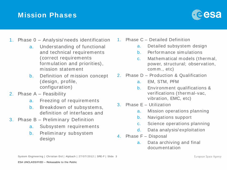
Mission Phases
1. Phase 0 – Analysis/needs identification a. Understanding of functional
and technical requirements (correct requirements formulation and priorities), mission statement
b. Definition of mission concept (design, profile, configuration)
2. Phase A – Feasibility a. Freezing of requirements b. Breakdown of subsystems,
definition of interfaces and 3. Phase B – Preliminary Definition
a. Subsystem requirements b. Preliminary subsystem
design
1. Phase C – Detailed Definition a. Detailed subsystem design b. Performance simulations c. Mathematical models (thermal,
power, structural; observation, comm., etc)
2. Phase D – Production & Qualification a. EM, STM, PFM b. Environment qualifications &
verifications (thermal-vac, vibration, EMC, etc)
3. Phase E – Utilization a. Mission operations planning b. Navigations support c. Science operations planning d. Data analysis/exploitation
4. Phase F – Disposal a. Data archiving and final
documentation

System Engineering | Christian Erd | Alpbach | 27/07/2012 | SRE-F | Slide 4
ESA UNCLASSIFIED – Releasable to the Public
Approximate Timeline of Phases
Activity Approximate Duration ESA Internal Assessment Phase 0 1.25 yrs Industrial Assessment Phase A 2.25 yrs Definition Phase B1 0.5 yrs Preparation of Implementation Phase 1 yr Implementation Phase B2/C/D 5 – 7 yrs

System Engineering | Christian Erd | Alpbach | 27/07/2012 | SRE-F | Slide 5
ESA UNCLASSIFIED – Releasable to the Public
Properties of Requirements
1. Requirements: Formal statement expressing what is needed to fulfil the mission objectives
2. Mission statement: captures the objectives and measurements required in a single sentence
3. Requirements should be product related, not process related 4. Good Examples:
a. The mission shall provide a measurement of the x constant with an accuracy better than 10–13
b. The mission shall allow scanning of the sky with an angular rate of 60 arsec/s around an axis of rotation which is 50°±0.1° away from the Sun direction
c. The mission shall have a nominal in-orbit duration of 4 years 5. Bad Examples:
a. The system design shall maximise the spectral resolution b. The mass shall be below 1000 kg
6. Clear requirements are key to good design 7. Requirements are hierarchical: lower level system requirements shall come
from higher level mission requirements

System Engineering | Christian Erd | Alpbach | 27/07/2012 | SRE-F | Slide 6
ESA UNCLASSIFIED – Releasable to the Public
Requirements Example
The science telemetry shall be downloaded using Ka-band telemetry
Good or Bad ??

System Engineering | Christian Erd | Alpbach | 27/07/2012 | SRE-F | Slide 7
ESA UNCLASSIFIED – Releasable to the Public
Requirements & Design Drivers
1. Identification of design drivers is result of requirements analysis a. First iteration during definition of mission concept
2. Design drivers constrain flexibility of system design there should be as few as possible!
3. Classification of requirements: unavoidable – negotiable
4. Typical (expected) unavoidable design drivers for outer planet missions a. Power generation b. Communications
5. Negotiable (examples):
a. Telemetry downlink b. Mission profile: mission duration, flybys, sequence of events

System Engineering | Christian Erd | Alpbach | 27/07/2012 | SRE-F | Slide 8
ESA UNCLASSIFIED – Releasable to the Public
Design Driver – Distance
http://nssdc.gsfc.nasa.gov/planetary/factsheet
1. (solar) Power generation
2. Telemetry slant range

System Engineering | Christian Erd | Alpbach | 27/07/2012 | SRE-F | Slide 9
ESA UNCLASSIFIED – Releasable to the Public
Design Driver – Environment
1. Example: Jupiter mission
1.E+03
1.E+04
1.E+05
1.E+06
1.E+07
1.E+08
1.E+09
0 2 4 6 8 10 12 14 16 18 20
Shielding Thickness [mm Al - solid sphere]
Dose
[rad
(Si)]
JGO (full mission)GEO (12 year mission)MEO (12 year mission)
Shieldose

System Engineering | Christian Erd | Alpbach | 27/07/2012 | SRE-F | Slide 10
ESA UNCLASSIFIED – Releasable to the Public
Design Driver – Planetary Protection
Planet Priorities Mission Type
Mission Category
Not of direct interest for understanding the process of chemical evolution. No protection of such planets is warranted.
Any I
Of significant interest relative to the process of chemical evolution and the origin of life, but only a remote chance that contamination by spacecraft could compromise future investigations
Any II
Of significant interest relative to the process of chemical evolution and the origin of life and for which scientific opinion provides a significant chance of contamination which could compromise future investigations.
Flyby, Orbiter
III
Lander, Probe
IV
Any solar system body Earth-Return
V

System Engineering | Christian Erd | Alpbach | 27/07/2012 | SRE-F | Slide 11
ESA UNCLASSIFIED – Releasable to the Public
Planetary Protection – Target Classification
1. Category I: Flyby, Orbiter, Lander: Undifferentiated, metamorphosed asteroids; others TBD
2. Category II: Flyby, Orbiter, Lander: Venus; Moon (with organic inventory); Comets; Carbonaceous Chondrite Asteroids; Jupiter; Saturn; Uranus; Neptune; Ganymede*; Titan*; Triton*; Pluto/Charon*; Ceres; Kuiper-Belt Objects > 1/2 the size of Pluto*; Kuiper-Belt Objects < 1/2 the size of Pluto; others TBD
3. Category III: Flyby, Orbiters: Mars; Europa; Enceladus; others TBD
4. Category IV: Lander Missions: Mars; Europa; others TBD
5. Category V: Any Earth-return mission. a. “Restricted Earth return”: Mars; Europa; others TBD b. “Unrestricted Earth return”: Venus, Moon; others TBD
* The mission-specific assignment of these bodies to Category II must be supported by an analysis of the “remote” potential for contamination of the liquid-water environments that may exist beneath their surfaces (a probability of introducing 1 viable terrestrial organism of <10–4), addressing both the existence of such environments and the prospects of accessing them.

System Engineering | Christian Erd | Alpbach | 27/07/2012 | SRE-F | Slide 12
ESA UNCLASSIFIED – Releasable to the Public
Spacecraft Subsystems
Structure
Communi- cations
Propulsion
Power
Avionics AOCS
Thermal
Configuration Payload
Launcher

System Engineering | Christian Erd | Alpbach | 27/07/2012 | SRE-F | Slide 13
ESA UNCLASSIFIED – Releasable to the Public
Trade-off
1. Trade-off allows exploring alternative solutions to a baseline
2. The parameter space needs to be prepared, and an evaluation criterion shall be established
3. Most common criteria: mass, cost; several system properties can be translated into them –
a. Power consumption generation of more power solar array size mass
b. Higher telemetry volume larger HGA, more power for TM&C mass
c. Very complex solutions more effort for verification longer integration time cost
Mass Cost
System Performance

System Engineering | Christian Erd | Alpbach | 27/07/2012 | SRE-F | Slide 14
ESA UNCLASSIFIED – Releasable to the Public
Trade-off Example: optimisation of solar array mass
1. Cover glass thickness: a. Thicker cover glass: better protection
against radiation, more mass b. Thinner cover glass: less mass, higher
degradation of solar cells
Radiation damage Cover glass obscuration

System Engineering | Christian Erd | Alpbach | 27/07/2012 | SRE-F | Slide 15
ESA UNCLASSIFIED – Releasable to the Public
Orbital Elements
1. Orbital plane is defined by a. The right ascension of the
ascending node Ω b. The inclination i
2. Orientation of the orbital trajectory (ellipse) is defined by
a. The argument of periapsis ω b. Eccentricity of the orbit e c. Semi-major axis
3. Reference times a. Epoch is the time since last
passage of periapsis b. The reference date for one
periapsis passage

System Engineering | Christian Erd | Alpbach | 27/07/2012 | SRE-F | Slide 16
ESA UNCLASSIFIED – Releasable to the Public
Other Local Coordinate Systems
1. Magnetic coordinates offset from bulk coordinates
2. Local coordinates rotating with the planet
3. Also left-handed systems in use!
4. Local coordinates of moons a. Similar to local planet
coordinates b. Longitude =0 at
meridian facing planet
Europa

System Engineering | Christian Erd | Alpbach | 27/07/2012 | SRE-F | Slide 17
ESA UNCLASSIFIED – Releasable to the Public
Technology Readiness Levels
System Engineering | Christian Erd | Alpbach | 27/07/2012 | SRE-F | Slide 18
ESA UNCLASSIFIED – Releasable to the Public
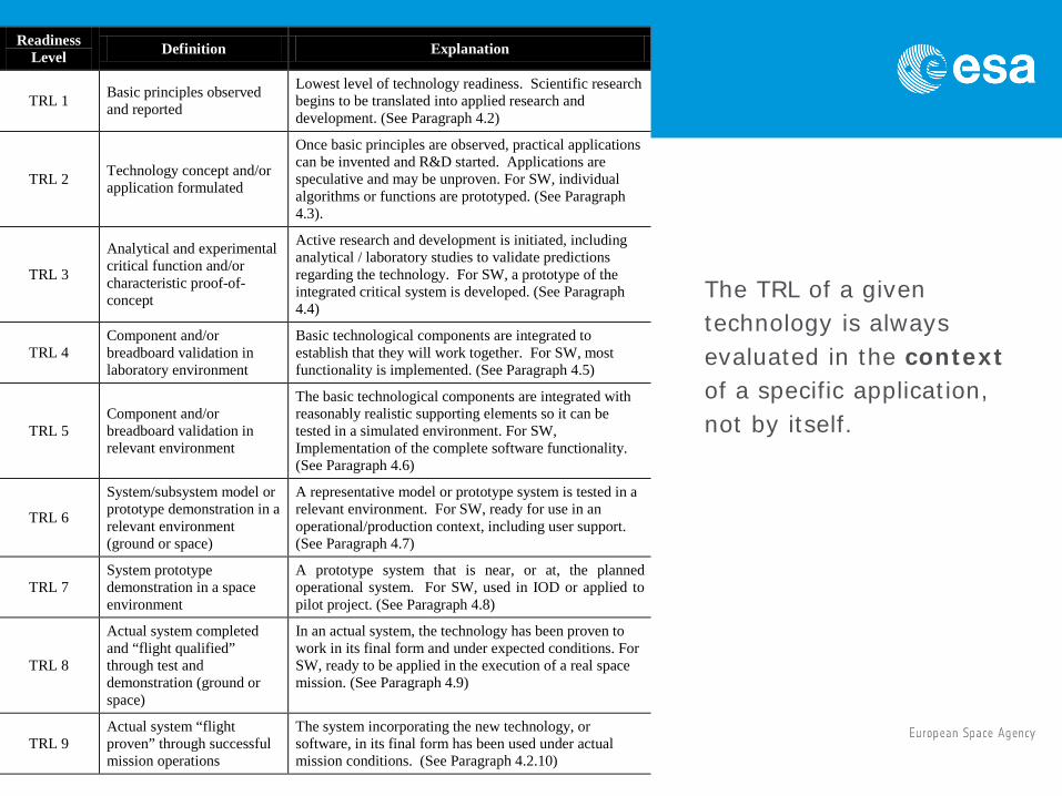
The TRL of a given technology is always evaluated in the context of a specific application, not by itself.
Readiness Level Definition Explanation
TRL 1 Basic principles observed and reported
Lowest level of technology readiness. Scientific research begins to be translated into applied research and development. (See Paragraph 4.2)
TRL 2 Technology concept and/or application formulated
Once basic principles are observed, practical applications can be invented and R&D started. Applications are speculative and may be unproven. For SW, individual algorithms or functions are prototyped. (See Paragraph 4.3).
TRL 3
Analytical and experimental critical function and/or characteristic proof-of-concept
Active research and development is initiated, including analytical / laboratory studies to validate predictions regarding the technology. For SW, a prototype of the integrated critical system is developed. (See Paragraph 4.4)
TRL 4 Component and/or breadboard validation in laboratory environment
Basic technological components are integrated to establish that they will work together. For SW, most functionality is implemented. (See Paragraph 4.5)
TRL 5 Component and/or breadboard validation in relevant environment
The basic technological components are integrated with reasonably realistic supporting elements so it can be tested in a simulated environment. For SW, Implementation of the complete software functionality. (See Paragraph 4.6)
TRL 6
System/subsystem model or prototype demonstration in a relevant environment (ground or space)
A representative model or prototype system is tested in a relevant environment. For SW, ready for use in an operational/production context, including user support. (See Paragraph 4.7)
TRL 7 System prototype demonstration in a space environment
A prototype system that is near, or at, the planned operational system. For SW, used in IOD or applied to pilot project. (See Paragraph 4.8)
TRL 8
Actual system completed and “flight qualified” through test and demonstration (ground or space)
In an actual system, the technology has been proven to work in its final form and under expected conditions. For SW, ready to be applied in the execution of a real space mission. (See Paragraph 4.9)
TRL 9 Actual system “flight proven” through successful mission operations
The system incorporating the new technology, or software, in its final form has been used under actual mission conditions. (See Paragraph 4.2.10)

System Engineering | Christian Erd | Alpbach | 27/07/2012 | SRE-F | Slide 19
ESA UNCLASSIFIED – Releasable to the Public
Margins – Contingencies
1. Equipment level margins according to maturity a. 5% for off-the-shelf items (no changes) b. 10% for off-the-shelf items with minor modifications c. 20% for new designs, new developments, major modifications
2. System margin (at least 20%) a. On top of and in addition to equipment margins; applied after
summing best estimates + margin b. Two options for the propellant calculation +10% margin + 2%
residuals – Margin on total dry mass and margin on launcher: typically
used during early study phases +10% margin – Margin on maximum separated mass: typically used later,
when mission analysis and launcher analysis become available
3. Always keep lots of margins 4. “Margin philosophy for Science Assessment Studies” (in library)

System Engineering | Christian Erd | Alpbach | 27/07/2012 | SRE-F | Slide 20
ESA UNCLASSIFIED – Releasable to the Public
Spacecraft Subsystems
Structure
Communi- cations
Propulsion
Power
Avionics AOCS
Thermal
Configuration Payload
Launcher

System Engineering | Christian Erd | Alpbach | 27/07/2012 | SRE-F | Slide 21
ESA UNCLASSIFIED – Releasable to the Public
Power – Nuclear Sources
1. Basically using heat generated by radioactive decay and a thermo-electric converter
2. Degradation a. Half life: Pu (88 yrs), 241Am (433 yrs) b. Themo-electric element: ~0.8% /yr
3. Radioisotope Heating Unit (RHU)
a. US: 1 W 40 g b. Rus: 8 W 200 g
Name Electrical Thermal Mass
MMRTG (238Pu) 110 W 2000 W 45 kg
ASRG (238Pu) 160 W 500 W 34 kg
ESA (Am2O3) <1 W/kg

System Engineering | Christian Erd | Alpbach | 27/07/2012 | SRE-F | Slide 22
ESA UNCLASSIFIED – Releasable to the Public
Power – Solar Arrays
1. Rosetta: 62 m2, Si technology, 443 W at 5.35 AU
2. JUICE: 64 m2, Triple junction GaAs Low-Intensity-Low-Temperature (LILT) technology, ~30% efficiency (BOL)
3. Physical properties (typical): 9.4 W/m2, 3 W /kg
4. Radiation damage (NIEL=Non-Ionising Energy Loss)
a. Protons: ∫𝑑Φ𝑝+ 𝐸
𝑑𝐸𝑁𝑁𝑁𝑁𝑝+ 𝑁 𝑑𝑁
b. Electrons: ∫𝑑Φ𝑒– 𝐸
𝑑𝐸𝑁𝑁𝐸𝑁𝑒–(𝐸)𝑎
𝑁𝑁𝐸𝑁𝑒–(1𝑀𝑀𝑀) 𝑎−1 𝑑𝑁
5. Need to include batteries for energy storage during eclipse!

System Engineering | Christian Erd | Alpbach | 27/07/2012 | SRE-F | Slide 23
ESA UNCLASSIFIED – Releasable to the Public
Power – Solar Arrays
-160 -140 -120 -100 -80 -60 -40 -20 0 20 4024
26
28
30
32
34
36
η
3.7 % AM0 BOL
ηAM0 BOL
Effic
ienc
y [%
]
Temperature [°C]1E14 1E15 1E16
0.2
0.3
0.4
0.5
0.6
0.7
0.8
0.9
1.0
1.1
AM0 relative degredation curve (established under room temperature)
η/η 0
1MeV electron fluence [cm-2]
Relative degredation of 3G28 solar cells (established under LILT conditions)
cell 73-7 cell 73-10 cell 92-3
Radiation Damage Efficiency
Radiation models at SPENVIS: http://www.spenvis.oma.be

System Engineering | Christian Erd | Alpbach | 27/07/2012 | SRE-F | Slide 24
ESA UNCLASSIFIED – Releasable to the Public
Communications
1. Telemetry budget, receiver margin: Eb/N0 ratio of received-energy-per-bit to noise-density
2. Transmitter a. P transmitter power b. Ll transmitter line loss c. Gt transmitter antenna gain (area, shape, λ–2)
3. Transmission a. Ls space loss (slant range) b. La transmission path loss (atmosphere,
etc) 4. Receiver
a. Gr receiver antenna gain b. kTs system noise energy
5. Data rate: R
𝑁𝑏𝑁0
=𝑃 ∙ 𝑁𝑙 ∙ 𝐺𝑡 ∙ 𝑁𝑠 ∙ 𝑁𝑎 ∙ 𝐺𝑟
𝑘 ∙ 𝑇𝑠 ∙ 𝑅
see also in SMAD

System Engineering | Christian Erd | Alpbach | 27/07/2012 | SRE-F | Slide 25
ESA UNCLASSIFIED – Releasable to the Public
Communications
1. High Gain Antenna (HGA) versus pointing performance 2. Optimum antenna diameter for known AOCS off-pointing 3. Further iteration to be done once AOCS performance is known
Diam1
Diam2 > Diam1Pointin
P
1
2
3
4
(the
Diam1
Diam2 > Diam1Pointin
P
11
22
33
44
(the
Parabolic reflector antenna @ 32,05GHz
0,00
0,05
0,10
0,15
0,20
0,25
0,30
0,35
2 2,2 2,4 2,6 2,8 3 4 5 6
Antenna diameter [m]
Dou
ble
side
d be
amw
idth
[deg
]
51,50
52,00
52,50
53,00
53,50
54,00
54,50
55,00
55,50
56,00
Gai
n w
ith o
ff-po
intin
g [d
Bi]
3dB double sided beamwidth [deg] Gain with off-pointing of 0,1deg [dBi]see also in SMAD

System Engineering | Christian Erd | Alpbach | 27/07/2012 | SRE-F | Slide 26
ESA UNCLASSIFIED – Releasable to the Public
Attitude and Orbit Control System
1. Allows maintaining the desired spacecraft attitudes 2. Trade-off: spinner versus 3-axis stabilized 3. Composed of
a. Sensors (to measure actual attitude) – Star trackers measure attitude wrt to inertial directions and
have accuracy between 1 arcsec and 1 arcmin – Sun sensors have accuracy between 20 arcsec and – 1 deg – Gyros measure angular rates and can be used together with
Star trackers for high accuracy pointing b. Actuators (to achieve desired attitude)
– Reaction wheels – Thrusters
4. Choice of sensors and actuators widely depends on requirements

System Engineering | Christian Erd | Alpbach | 27/07/2012 | SRE-F | Slide 28
ESA UNCLASSIFIED – Releasable to the Public
Attitude Control Definitions
see also ECSS-E-ST-60-10C
MPE mean performance error APE absolute performance error RPE relative performance error AKE absolute knowledge error MKE mean knowledge error RKE relative knowledge error PDE performance drift error PRE performance reproducibility error

System Engineering | Christian Erd | Alpbach | 27/07/2012 | SRE-F | Slide 29
ESA UNCLASSIFIED – Releasable to the Public
Propulsion
1. The subsystem in charge of satellite manoeuvring 2. Includes thrusters, tanks, piping and valves 3. Many technologies available
a. Solid thruster: single one off, high thrust b. Monopropellant c. Bi-propellant: d. Solar Electric
4. For orbital manoeuvres with high ΔV: “high” Isp (> 300 s) – e.g. bipropellant or electric propulsion
5. For orbital manoeuvres with low ΔV: “medium” Isp and thrust (~1 N) – e.g. monopropellant - hydrazine
6. For fine control: “low” thrust: (≤10 mN) – cold gas or FEEP based
7. Specifics for deep space missions: a. Pressurized tanks will be necessary (engine re-start) b. Valve isolation and redundancy
500 N engine
22N thruster

System Engineering | Christian Erd | Alpbach | 27/07/2012 | SRE-F | Slide 30
ESA UNCLASSIFIED – Releasable to the Public
Propulsion Design
1. Propellant mass 𝑀prop = 𝑀dry × (𝑒∆𝑣
𝑔∙𝐼sp − 1)
2. Needs to include: a. All deterministic manoeuvres (ΔV) b. Navigations manoeuvres (stochastic) c. All AOCS needs (momentum wheel off-loading, SAFE mode,
etc) 3. Propulsion system dry mass rule of thumb: 0.2 × Mprop

System Engineering | Christian Erd | Alpbach | 27/07/2012 | SRE-F | Slide 31
ESA UNCLASSIFIED – Releasable to the Public
Example Propulsion System

System Engineering | Christian Erd | Alpbach | 27/07/2012 | SRE-F | Slide 32
ESA UNCLASSIFIED – Releasable to the Public
Propulsion – RCS Thrusters
1. Definition and location of thrusters
2. Force-free layout
3. Thrusting in any direction in any attitude
4. Redundancy required
5. RCS Thrusters could act as backup for main engine
Messenger RCS layout

System Engineering | Christian Erd | Alpbach | 27/07/2012 | SRE-F | Slide 33
ESA UNCLASSIFIED – Releasable to the Public
Avionics
1. The subsystem in charge of handling all mission and system onboard data, of hosting and running the onboard software
2. Composed of a. On-board computer (CDMU), Mass Memory Unit,
RTUs/interface electronics 3. Often payload has its own computer for on-board science data
processing

System Engineering | Christian Erd | Alpbach | 27/07/2012 | SRE-F | Slide 34
ESA UNCLASSIFIED – Releasable to the Public
Thermal
1. The subsystem that allows keeping the spacecraft and payload temperatures within allowable limits
2. Generally, separated thermal control for spacecraft and payload due to different temperature requirements
3. Basic principles: a. Insulate the spacecraft from the
environment to keep stable temperatures inside and provide an aperture for dissipation of excess heat (radiator).
b. During eclipse provide heating power to keep the spacecraft warm
4. Composed of : thermal blankets (MLI), external paints to modify optical properties, radiator(s) and associated heat transport devices (heat pipes, high conductivity paths)

System Engineering | Christian Erd | Alpbach | 27/07/2012 | SRE-F | Slide 35
ESA UNCLASSIFIED – Releasable to the Public
Thermal Design
1. Spacecraft Thermal verification: 2. Assume single node and make thermal balance
𝑄intin + 𝑄extin = 𝑄out
𝑄out = ε𝜎𝑇4𝐴rad
𝑄int𝑖𝑖 = 𝑃dissipated
𝑄extin = 𝛼𝐴exposed𝑆 + 𝑄PlanetIR + 𝑄Albedo
3. Solve first for Arad (radiator area) fixing max allowed T and optical
properties 4. Solve then to find Pdissipated needed to keep T within limits in eclipse for
Arad

System Engineering | Christian Erd | Alpbach | 27/07/2012 | SRE-F | Slide 36
ESA UNCLASSIFIED – Releasable to the Public
Structure
1. The subsystem that supports all the spacecraft equipment and payload and allows withstanding the mission loads
2. Primary structure: Satellite “backbone”, carrying the loads transmitted to the spacecraft by the launcher through the launcher interface. It includes external panels if they support high mass components
3. Secondary structure: supports harness, propellant lines, and panels and brackets for small components
4. Structure is a large fraction of the total satellite mass: ~30 % 5. Many different types and shapes depending on mission architecture

System Engineering | Christian Erd | Alpbach | 27/07/2012 | SRE-F | Slide 37
ESA UNCLASSIFIED – Releasable to the Public
System Summary
1. Budgets: Mass, Power
2. Mission profile & lifetime
3. Launcher: launch mass, fairing
4. Total system margin

System Engineering | Christian Erd | Alpbach | 27/07/2012 | SRE-F | Slide 38
ESA UNCLASSIFIED – Releasable to the Public
Launch !