system description - the fire alarm store · table of contents system description, autrosafe...
TRANSCRIPT
116-P-ASAFE-SYSTEMD/EGB Rev. B, 2010-02-01
System Description
AutroSafe Interactive Fire Detection System
Release 4
COPYRIGHT ©
This publication, or parts thereof, may not be reproduced in any form, by any method, for any purpose. Autronica Fire and Security AS and its subsidaries assume no responsibility for any errors that may appear in the publication, or for damages arising from the information in it. No information in this publication should be regarded as a warranty made by Autronica Fire and Security. The information in this publication may be updated without notice. Product names mentioned in this publication may be trademarks. They are used only for identification.
E-1
676
This product contains static-sensitive devices. Avoid any electrostatic discharge.
The WEEE Directive
When the marking below is shown on the product and/or its literature, it means that the product should not be disposed with other household wastes at the end of its life cycle. During waste treatment, disposal and collection, please separate the product from other types of wastes and recycle it responsibly to promote the sustainable reuse of material resources. This product should not be mixed with other commercial wastes for disposal.

Table of Contents
System Description, AutroSafe Interactive Fire Detection System, Release 4, 116-P-ASAFE-SYSTEMD/EGB Rev. B, 2010-02-01, Autronica Fire and Security AS
Page 1
Table of Contents
1. Introduction.......................................................................4 1.1 About the Handbook ......................................................................... 4 1.2 The Reader ....................................................................................... 4 1.3 Reference Documentation ................................................................ 4
2. Compliance to Standards.................................................5 2.1 Compliance with Regulations and Standards ................................... 5 2.2 EN 54-2 Functionality List ................................................................. 5
2.2.1 Optional functions with requirements of this European Standard.................................................................................. 6
2.2.2 Functions relating to other parts of EN 54 .............................. 7 2.2.3 Ancillary functions not required by this European
Standard.................................................................................. 7 2.3 CE Marking Information .................................................................... 8 2.4 Definitions.......................................................................................... 8
3. System Characteristics ....................................................9 3.1 Introduction........................................................................................ 9 3.2 Onshore Market / Maritime Market.................................................... 9 3.3 Petrochemical, Oil & Gas Market ...................................................... 10 3.4 AutroNet - the Local Area Network ................................................... 11 3.5 AutroFieldBus – the Low Level Protocol for Field Devices ............ 11 3.6 System Capacity ............................................................................... 11 3.7 Zoning Concept ................................................................................. 12 3.8 Communication Ports........................................................................ 13 3.9 AutroMaster ISEMS........................................................................... 13 3.10 Interfacing Peripheral Equipment...................................................... 13 3.11 Language Options............................................................................. 14 3.12 Environmental Requirements............................................................ 14 3.13 Configuration / Service...................................................................... 14
3.13.1 Downloading from one central point ....................................... 14 3.14 SelfVerify® Function ......................................................................... 15 3.15 Operation Classes for different Detection Methods .......................... 15 3.16 Performance Classes for Environmental Adaptivity.......................... 16 3.17 Interactive Detectors with Dynamic Filtering (DYFI+) ....................... 17 3.18 Built-in Short-circuit Isolator .............................................................. 18 3.19 Integrity of Transmissions Paths ....................................................... 18
4. System Units .....................................................................19

Table of Contents
System Description, AutroSafe Interactive Fire Detection System, Release 4, 116-P-ASAFE-SYSTEMD/EGB Rev. B, 2010-02-01, Autronica Fire and Security AS
Page 2
5. Examples of Network Solutions ......................................20 5.1 Introduction........................................................................................ 20 5.2 General Guidelines ........................................................................... 20 5.3 Phoenix Ethernet Switches ............................................................... 21
5.3.1 Overview ................................................................................. 21 5.3.2 Twisted Pair ............................................................................ 22 5.3.3 Multi-mode Fibre ..................................................................... 22 5.3.4 Single-mode Fibre................................................................... 23
5.4 Network Solution – Example 1 .......................................................... 24 5.5 Network Solution – Example 2 .......................................................... 24 5.6 Network Solution – Example 3 .......................................................... 25 5.7 Network Solution – Example 4 .......................................................... 25 5.8 Network Solution – Example 5 .......................................................... 26 5.9 Network Solution – Example 6 .......................................................... 27 5.10 Network Solution – Example 7 .......................................................... 28 5.11 Network Solution – Example 8 .......................................................... 28
6. Internal Modules ...............................................................29 6.1 Module Capacity inside the Fire Alarm Control Panel and
Controller........................................................................................... 29 6.2 Overview ........................................................................................... 29
7. Loop Units .........................................................................31
8. Detection Loops................................................................37 8.1 Description ........................................................................................ 37 8.2 Branch-offs ........................................................................................ 37 8.3 Capacity on the Detection Loop........................................................ 38
9. Cable Specifications........................................................39
10. Power Distribution, Calculation and Consumption .......41 10.1 Introduction........................................................................................ 41 10.2 Power Calculation Example – 4 Power Cabinets BP-405 ............... 42 10.3 Power Consumption.......................................................................... 44
10.3.1 Mains Power ........................................................................... 44 10.3.2 System Units ........................................................................... 45 10.3.3 Loop Units ............................................................................... 45 10.3.4 Phoenix Ethernet Switches ..................................................... 45
11. Appendix ...........................................................................46 11.1 Zoning Concept ................................................................................. 46
11.1.1 General ................................................................................... 46 11.1.2 Detection Zone........................................................................ 46 11.1.3 Alarm Zone.............................................................................. 47 11.1.4 Operation Zone ....................................................................... 47
11.2 Configuration Examples .................................................................... 48 11.2.1 Simple Configuration Example................................................ 48 11.2.2 Configuration Example with Several Operation Zones.......... 50

Table of Contents
System Description, AutroSafe Interactive Fire Detection System, Release 4, 116-P-ASAFE-SYSTEMD/EGB Rev. B, 2010-02-01, Autronica Fire and Security AS
Page 3
12. Reader’s Comments .........................................................53
Introduction
System Description, AutroSafe Interactive Fire Detection System, Release 4, 116-P-ASAFE-SYSTEMD/EGB Rev. B, 2010-02-01, Autronica Fire and Security AS
Page 4
1. Introduction
1.1 About the Handbook
This document provides a description of the AutroSafe Interactive Fire Detection System, Release 4.
1.2 The Reader
This handbook is intended for consultants, sales personnel, potential customers and distributors.
1.3 Reference Documentation
The table below shows an overview of the technical marketing documentation for AutroSafe Interactive Fire Detection System, Release 4.
Document Name Part number File name System Description 116-P-ASAFE-SYSTEMD/EGB asafesystem_egb Installation Handbook 116-P-ASAFE-INSTALL/DGB asafeinstall_dgb Commissioning Handbook 116-P-ASAFE-COMMISS/EGB asafecommiss_egb Connecting Loop Units 116-P-CONNECTLOOPUNIT/DGB connectloopunit_dgb Operator’s Handbook 116-P-ASAFE-OPERATE/FGB asafeoperate_fgb User Guide 116-P-ASAFE-USERGUI/LGB asafeusergui_lgb Wall Chart 116-P-ASAFE-WALLCHA/LGB asafewallcha_lgb Menu Structure 116-P-ASAFE-MENUSTR/MGB asafemenustr_mgb Datasheet; Fire Alarm Control Panel BS-420 116-P-BS420/CGB bs420_cgb Datasheet; Operator Panel BS-430 116-P-BS430/CGB bs430_cgb Datasheet; Repeater Panel BU-BV-420 116-P-BUBV420/CGB bubv420_cgb Datasheet; Power Cabinet BP-405 116-P-BP405/CGB bp405_cgb Datasheet; Controller BC-420 116-P-BC420/CGB bc420_cgb
Compliance to Standards
System Description, AutroSafe Interactive Fire Detection System, Release 4, 116-P-ASAFE-SYSTEMD/EGB Rev. B, 2010-02-01, Autronica Fire and Security AS
Page 5
2. Compliance to Standards
2.1 Compliance with Regulations and Standards
AutroSafe Interactive Fire Detection System, Release 4, complies with IEC-61508 SIL2 requirements, C.E.N. EN 54-2, EN 54-4 and EN 54-13 regulations, FM regulations (Factory Mutual) and the maritime SOLAS requirements (Safety Of Life At Sea). Certified according to Construction Products Directive (CPD9 and Maritime Equipment Directive (MED).
2.2 EN 54-2 Functionality List
With reference to 12.2.1 in EN 54-2. h) a general description of the equipment, including a list of the: optional functions with requirements of this European Standard
(chapter 2.2.1 in this handbook) functions relating to other parts of EN 54 (chapter 0 in this
handbook) ancillary functions not required by this European Standard (chapter
2.2.3 in this handbook)
Compliance to Standards
System Description, AutroSafe Interactive Fire Detection System, Release 4, 116-P-ASAFE-SYSTEMD/EGB Rev. B, 2010-02-01, Autronica Fire and Security AS
Page 6
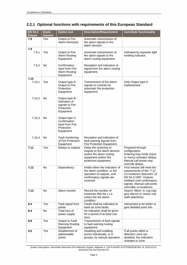
2.2.1 Optional functions with requirements of this European Standard
EN 54-2 Clause
Imple- mented
Option text Description/Requirement AutroSafe functionality
7.8 Yes Output to Fire Alarm Device(s)
Automatic transmission of fire alarm signals to fire alarm devices.
7.9 7.9.1
7.9.2
Yes No
Output to Fire Alarm Routing Equipment Confirmation input from Fire Alarm Routing Equipment
Automatic transmission of fire alarm signals to fire alarm routing equipment. Reception and indication of signal from fire alarm routing equipment.
Indicated by separate light emitting indicator.
7.10 7.10.1
7.10.2
7.10.3
7.10.4
Yes No No No
Output type A: Output to Fire Protection Equipment Output type B: Indication of signals to Fire Protection Equipment Output type C: Confirmation input from Fire Protection Equipment Fault monitoring of Fire Protection Equipment
Transmission of fire alarm signals to controls for automatic fire protection equipment. Reception and indication of fault warning signals from Fire Protection Equipment.
Only Output type A implemented
7.11 Yes Delays to outputs Delay the actioning of outputs to fire alarm devices and/or fire alarm routing equipment and/or fire protection equipment.
Prepared through configuration. Entering Day-mode (input or menu) activates delays. Manual call points may override delays.
7.12 No Dependency Inhibit either the indication of fire alarm condition, or the operation of outputs, until confirmatory signals are received.
First release will meet the requirements of the “7.12 Co-incidence detection” of EN 54-2:1997. Outputs inhibited until confirmatory signals. Manual call points overrides co-incidence.
7.13 No Alarm counter Record the number of instances that the c.i.e. enters the fire alarm condition.
Search ‘filters’ in Log may give alarms or resets only (with date/time).
8.3 Yes Fault signal from points
Faults shall be indicated at least as zone faults.
Interpreted to be better to give detailed point info.
8.4 No Total loss of power supply
An indication shall be given for a period of at least one hour.
8.9 Yes Output to Fault Warning Routing Equipment
Transmission of fault signals to fault warning routing equipment.
9.5 Yes Disablement of addressable points
Disabling and enabling points individually, or in groups, by manual operation.
If all points within a detection zone are disabled, the indication changes to zone
Compliance to Standards
System Description, AutroSafe Interactive Fire Detection System, Release 4, 116-P-ASAFE-SYSTEMD/EGB Rev. B, 2010-02-01, Autronica Fire and Security AS
Page 7
EN 54-2 Clause
Imple- mented
Option text Description/Requirement AutroSafe functionality
disablement.
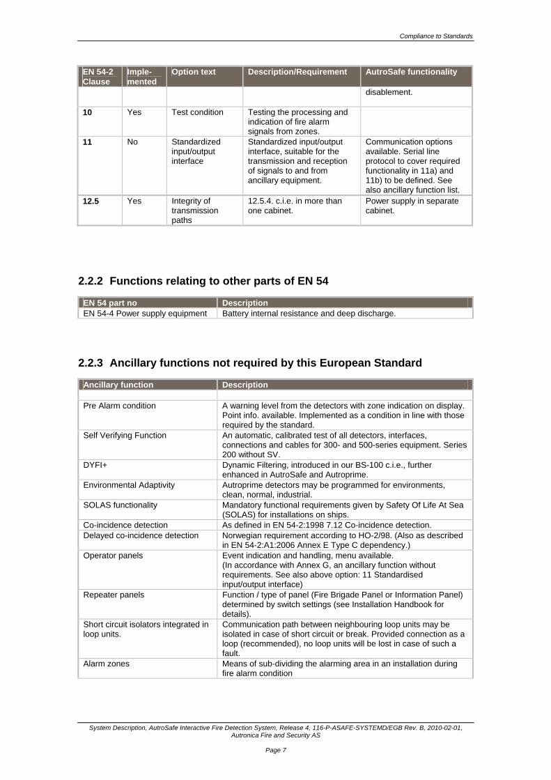
10 Yes Test condition Testing the processing and indication of fire alarm signals from zones.
11 No Standardized input/output interface
Standardized input/output interface, suitable for the transmission and reception of signals to and from ancillary equipment.
Communication options available. Serial line protocol to cover required functionality in 11a) and 11b) to be defined. See also ancillary function list.
12.5 Yes Integrity of transmission paths
12.5.4. c.i.e. in more than one cabinet.
Power supply in separate cabinet.
2.2.2 Functions relating to other parts of EN 54
EN 54 part no Description EN 54-4 Power supply equipment Battery internal resistance and deep discharge.
2.2.3 Ancillary functions not required by this European Standard
Ancillary function Description Pre Alarm condition A warning level from the detectors with zone indication on display.
Point info. available. Implemented as a condition in line with those required by the standard.
Self Verifying Function An automatic, calibrated test of all detectors, interfaces, connections and cables for 300- and 500-series equipment. Series 200 without SV.
DYFI+ Dynamic Filtering, introduced in our BS-100 c.i.e., further enhanced in AutroSafe and Autroprime.
Environmental Adaptivity Autroprime detectors may be programmed for environments, clean, normal, industrial.
SOLAS functionality Mandatory functional requirements given by Safety Of Life At Sea (SOLAS) for installations on ships.
Co-incidence detection As defined in EN 54-2:1998 7.12 Co-incidence detection. Delayed co-incidence detection Norwegian requirement according to HO-2/98. (Also as described
in EN 54-2:A1:2006 Annex E Type C dependency.) Operator panels Event indication and handling, menu available.
(In accordance with Annex G, an ancillary function without requirements. See also above option: 11 Standardised input/output interface)
Repeater panels Function / type of panel (Fire Brigade Panel or Information Panel) determined by switch settings (see Installation Handbook for details).
Short circuit isolators integrated in loop units.
Communication path between neighbouring loop units may be isolated in case of short circuit or break. Provided connection as a loop (recommended), no loop units will be lost in case of such a fault.
Alarm zones Means of sub-dividing the alarming area in an installation during fire alarm condition
Compliance to Standards
System Description, AutroSafe Interactive Fire Detection System, Release 4, 116-P-ASAFE-SYSTEMD/EGB Rev. B, 2010-02-01, Autronica Fire and Security AS
Page 8
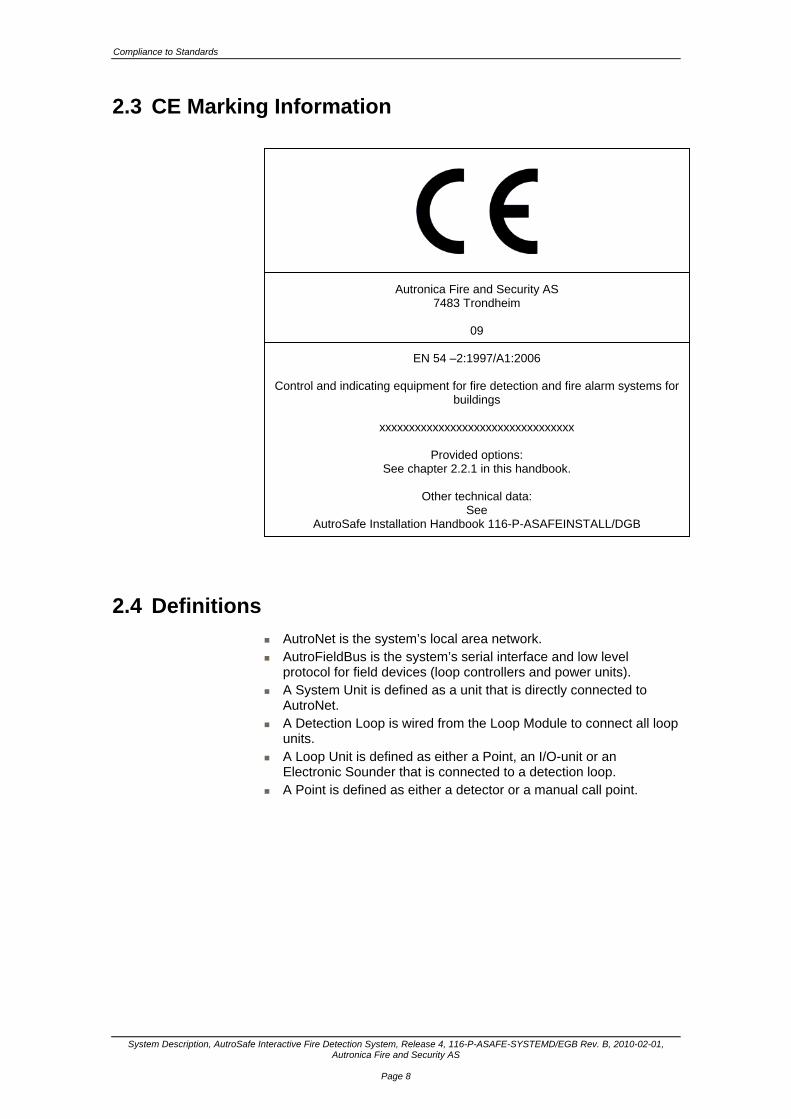
2.3 CE Marking Information
2.4 Definitions
AutroNet is the system’s local area network. AutroFieldBus is the system’s serial interface and low level
protocol for field devices (loop controllers and power units). A System Unit is defined as a unit that is directly connected to
AutroNet. A Detection Loop is wired from the Loop Module to connect all loop
units. A Loop Unit is defined as either a Point, an I/O-unit or an
Electronic Sounder that is connected to a detection loop. A Point is defined as either a detector or a manual call point.
Autronica Fire and Security AS 7483 Trondheim
09
EN 54 –2:1997/A1:2006
Control and indicating equipment for fire detection and fire alarm systems for buildings
xxxxxxxxxxxxxxxxxxxxxxxxxxxxxxxxx
Provided options:
See chapter 2.2.1 in this handbook.
Other technical data: See
AutroSafe Installation Handbook 116-P-ASAFEINSTALL/DGB

System Characteristics
System Description, AutroSafe Interactive Fire Detection System, Release 4, 116-P-ASAFE-SYSTEMD/EGB Rev. B, 2010-02-01, Autronica Fire and Security AS
Page 9
3. System Characteristics
3.1 Introduction
AutroSafe Interactive Fire Detection System, Release 4, provides advanced functionality within fire detection for a wide range of applications. The system is designed to meet requirements in the high-end segment of the land, maritime and offshore market, and is developed for worldwide standards and regulations. AutroSafe 4 operates on a high-speed and fully redundant Ethernet-based network solution; AutroNet, providing extremely fast data transmission. A maximum of 64 system units (panels, controllers) can be connected to the AutroNet. A standalone system is also possible, using the Fire Alarm Control Panel BS-420 (the mandatory panel in any system). The system has a great capacity, and the fact that all types of loop units can be connected to the same detection loop gives large flexibility.
3.2 Onshore Market / Maritime Market
The illustration below shows an example of an installation for the onshore and maritime market.
System Characteristics
System Description, AutroSafe Interactive Fire Detection System, Release 4, 116-P-ASAFE-SYSTEMD/EGB Rev. B, 2010-02-01, Autronica Fire and Security AS
Page 10
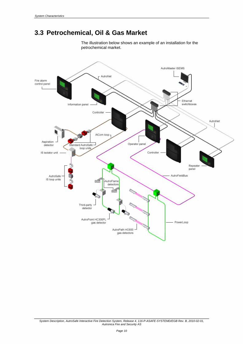
3.3 Petrochemical, Oil & Gas Market
The illustration below shows an example of an installation for the petrochemical market.
System Characteristics
System Description, AutroSafe Interactive Fire Detection System, Release 4, 116-P-ASAFE-SYSTEMD/EGB Rev. B, 2010-02-01, Autronica Fire and Security AS
Page 11
3.4 AutroNet - the Local Area Network
AutroSafe Interactive Fire Detection System, Release 4, features an Ethernet-based local area network called AutroNet. The main circuit board in each single panel/cabinet provides two Ethernet ports, enabling redundancy. AutroNet supports a maximum of 64 system units. For detailed information on network solutions, including guidelines and information on Ethernet switches, refer to Example of Network Solutions, chapter 5.
3.5 AutroFieldBus – the Low Level Protocol for Field Devices
AutroFieldBus is the system’s serial interface and low level protocol for field devices (loop controllers and power units). All power cabinets and field devices communicate on the AutroFieldBus to achieve fault monitoring and control.
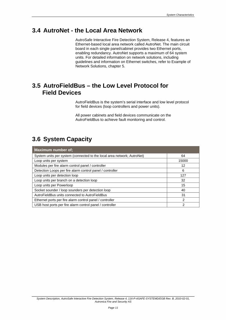
3.6 System Capacity
Maximum number of;
System units per system (connected to the local area network; AutroNet) 64
Loop units per system 15000
Modules per fire alarm control panel / controller 12
Detection Loops per fire alarm control panel / controller 6
Loop units per detection loop 127
Loop units per branch on a detection loop 32
Loop units per Powerloop 15
Socket sounder / loop sounders per detection loop 40
AutroFieldBus units connected to AutroFieldBus 31
Ethernet ports per fire alarm control panel / controller 2
USB host ports per fire alarm control panel / controller 2
System Characteristics
System Description, AutroSafe Interactive Fire Detection System, Release 4, 116-P-ASAFE-SYSTEMD/EGB Rev. B, 2010-02-01, Autronica Fire and Security AS
Page 12
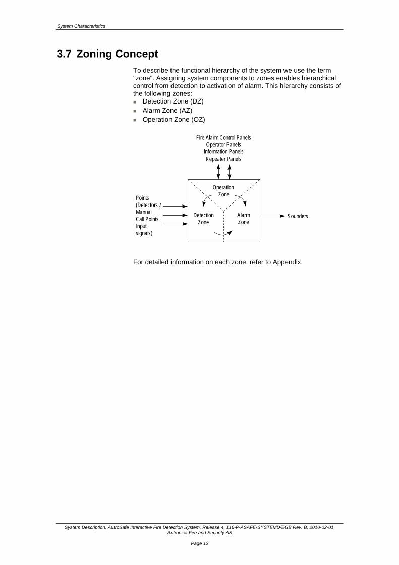
3.7 Zoning Concept
To describe the functional hierarchy of the system we use the term "zone". Assigning system components to zones enables hierarchical control from detection to activation of alarm. This hierarchy consists of the following zones: Detection Zone (DZ) Alarm Zone (AZ) Operation Zone (OZ)
Operation Zone
DetectionZone
AlarmZone
Fire Alarm Control PanelsOperator Panels
Information PanelsRepeater Panels
Points(Detectors /ManualCall PointsInputsignals)
Sounders
For detailed information on each zone, refer to Appendix.
System Characteristics
System Description, AutroSafe Interactive Fire Detection System, Release 4, 116-P-ASAFE-SYSTEMD/EGB Rev. B, 2010-02-01, Autronica Fire and Security AS
Page 13
3.8 Communication Ports
The system offers the following communication ports: 2 Ethernet ports for AutroNet and/or AutroCom, plus downloading
of configuration data and system software 1 AL_Com+ interface 1 RS-232, RS-422 or RS-485 serial port for communication with
third party equipment (AutroCom) 1 AutroFieldBus (AFB) interface 2 USB host ports for the connection of a printer and for the
connection of a memory stick for downloading configuration data and system software
FailSafe relay output
3.9 AutroMaster ISEMS
AutroMaster ISEMS is an Integrated Safety and Emergency Management System which can be used together with the AutroSafe Interactive Fire Detection System. The AutroMaster ISEMS has an intuitive control and monitoring interface, providing an easy-to-understand graphical presentation of the premises and events that may occur. Navigation is fast and instinctual, and the powerful zoom functions allow you to monitor all areas in great detail.
3.10 Interfacing Peripheral Equipment
For communication with peripheral equipment / third-party equipment the following protocols are used: ESPA 4.4.4, allowing connectivity with devices such as AutroTel
alarm routing via telephone networks and pocket paging systems. NMEA-0183, allowing connectivity with devices such as the
maritime Voyage Data Recorder (VDR). MODBUS, allowing connectivity with Programmable Logic
Controllers (PLC).

System Characteristics
System Description, AutroSafe Interactive Fire Detection System, Release 4, 116-P-ASAFE-SYSTEMD/EGB Rev. B, 2010-02-01, Autronica Fire and Security AS
Page 14
3.11 Language Options
AutroSafe version 4 supports the following languages (listed in alphabetical order): Danish Dutch English English (version intended for the Oil & Gas market) Finnish French German Hungarian Icelandic Italian Norwegian Polish Portuguese (Brazilian) Russian Spanish Swedish
3.12 Environmental Requirements
The equipment complies with environmental conditions of EN 60721-3-3:1995, class 3k5 (refer to EN 54-2, chapter 12.1.6). Ambient temperature: EN 54: -5° to +40° C Maritime requirements: -15° to +70° C Degree of protection: IEC-529/IP32
3.13 Configuration / Service
3.13.1 Downloading from one central point
Downloading of configuration data or system software to the entire system can be done from one central point. The USB port is used for downloading data from a USB memory stick. To replace the existing configuration data with new configuration data, a system restart must be performed after the configuration is downloaded.
System Characteristics
System Description, AutroSafe Interactive Fire Detection System, Release 4, 116-P-ASAFE-SYSTEMD/EGB Rev. B, 2010-02-01, Autronica Fire and Security AS
Page 15
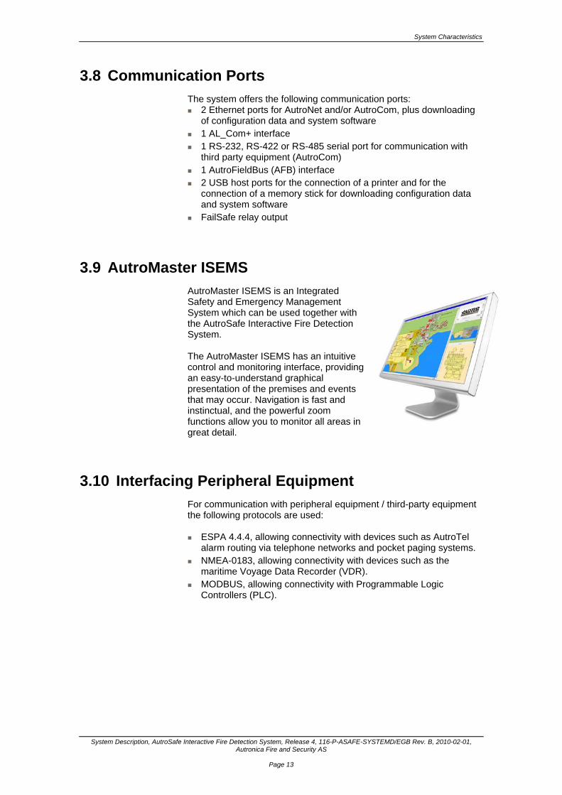
3.14 SelfVerify® Function
AutroSafe SelfVerify® solves all issues of manual maintenance, leaving time-consuming and costly physical testing no longer necessary. With AutroSafe SelfVerify®, the system checks all detectors, interfaces, connections and cables – from detector chamber to alarm output – every single day. Not only does the system test whether a detector is capable of provoking an alarm, it even verifies the sensitivity of every detector with a calibrated signal. The SelfVerify system ensures that each detector always responds to the correct alarm level. In the event of irregularities, the display on the operating panel will accurately pinpoint the source of any problem.
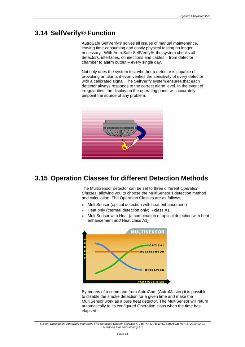
3.15 Operation Classes for different Detection Methods
The MultiSensor detector can be set to three different Operation Classes, allowing you to choose the MultiSensor’s detection method and calculation. The Operation Classes are as follows;
MultiSensor (optical detection with heat enhancement) Heat only (thermal detection only) - class A1 MultiSensor with Heat (a combination of optical detection with heat
enhancement and Heat class A1)
By means of a command from AutroCom (AutroMaster) it is possible to disable the smoke detection for a given time and make the MultiSensor work as a pure heat detector. The MultiSensor will return automatically to its configured Operation class when the time has elapsed.
System Characteristics
System Description, AutroSafe Interactive Fire Detection System, Release 4, 116-P-ASAFE-SYSTEMD/EGB Rev. B, 2010-02-01, Autronica Fire and Security AS
Page 16
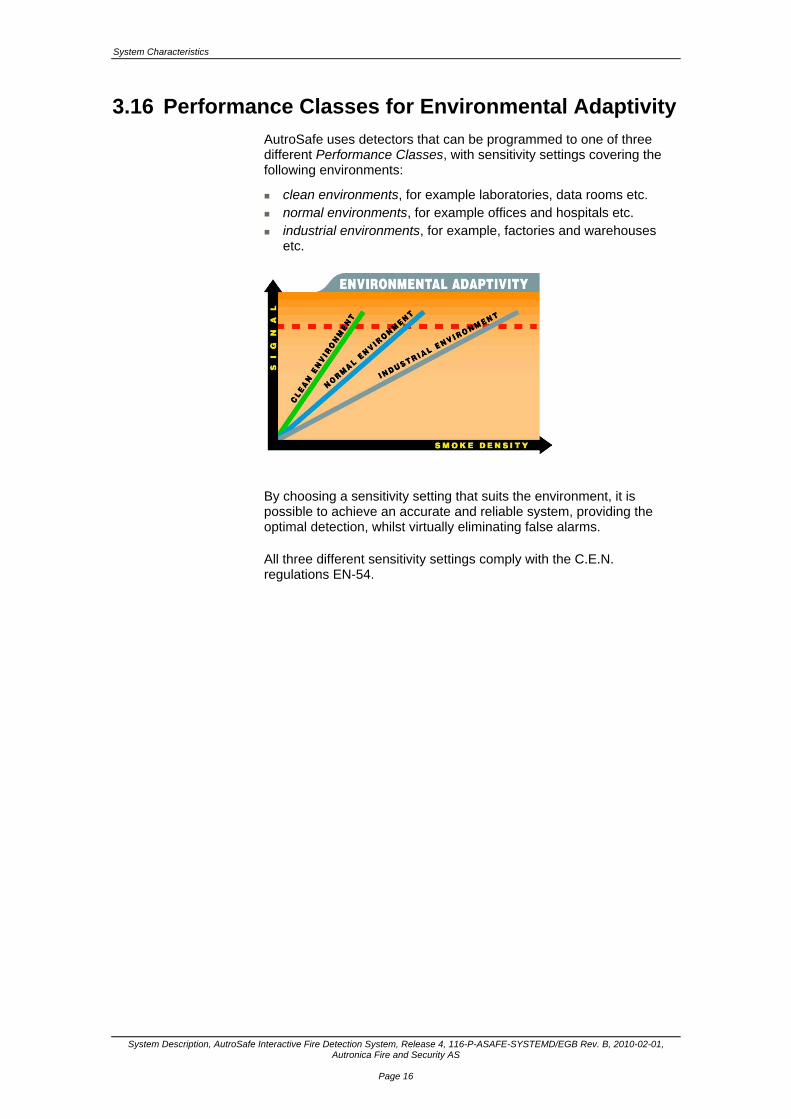
3.16 Performance Classes for Environmental Adaptivity
AutroSafe uses detectors that can be programmed to one of three different Performance Classes, with sensitivity settings covering the following environments:
clean environments, for example laboratories, data rooms etc. normal environments, for example offices and hospitals etc. industrial environments, for example, factories and warehouses
etc.
By choosing a sensitivity setting that suits the environment, it is possible to achieve an accurate and reliable system, providing the optimal detection, whilst virtually eliminating false alarms. All three different sensitivity settings comply with the C.E.N. regulations EN-54.

System Characteristics
System Description, AutroSafe Interactive Fire Detection System, Release 4, 116-P-ASAFE-SYSTEMD/EGB Rev. B, 2010-02-01, Autronica Fire and Security AS
Page 17
3.17 Interactive Detectors with Dynamic Filtering (DYFI+)
AutroSafe features detectors with the digital filter technology DYFI+. False alarms are virtually eliminated, and the system provides the earliest possible warning of a potential fire - before it becomes a problem. The DYFI+ digital filtering is present in each detector. Each detector has three different filter functions:
The smouldering fire filter provides accurate and quick detection in the event of a smouldering fire, i.e. in a situation where a potential fire with no flames develops during a longer period.
The transient filter virtually eliminates false alarms caused by phenomena that are not related to a real fire. Such phenomena can be short pulses caused by, for example, vapour, cigarette smoke etc.
The pollution filter maintains the chosen sensitivity throughout the detector’s entire lifetime, even with a polluted detector..
System Characteristics
System Description, AutroSafe Interactive Fire Detection System, Release 4, 116-P-ASAFE-SYSTEMD/EGB Rev. B, 2010-02-01, Autronica Fire and Security AS
Page 18
3.18 Built-in Short-circuit Isolator
The loop resistance on the detection loop is continously monitored to register a possible break or short-circuit on the detection loop. Each individual detector has a built-in short-circuit isolator. In the event of a short-circuit in the detector cable, the short-circuit location will be isolated as the short-circuit isolator will be activated in the detectors on either side.
3.19 Integrity of Transmissions Paths
Reference document EN 54-2, chapter 12.5.2. Means, specified and provided, to limit the consequences of faults (short-circuit or interruption): Detection loop: Built-in short-circuit isolator (no loop units lost in case of a short-
circuit or interruption). AutroFieldBus: Built-in short-circuit isolator (no loop units lost in case of a short-
circuit or interruption). AutroNet: The main circuit board in each single panel/cabinet provides two
Ethernet ports, enabling redundancy.
System Units
System Description, AutroSafe Interactive Fire Detection System, Release 4, 116-P-ASAFE-SYSTEMD/EGB Rev. B, 2010-02-01, Autronica Fire and Security AS
Page 19
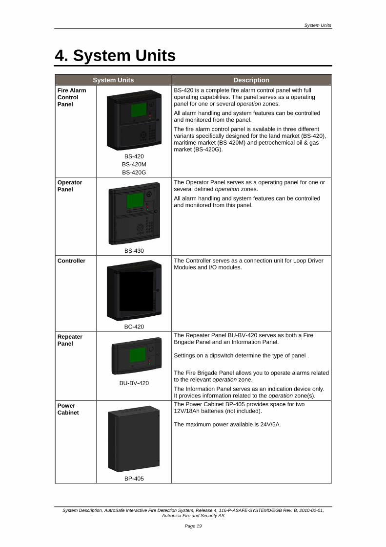
4. System Units System Units Description
Fire Alarm Control Panel
BS-420
BS-420M BS-420G
BS-420 is a complete fire alarm control panel with full operating capabilities. The panel serves as a operating panel for one or several operation zones.
All alarm handling and system features can be controlled and monitored from the panel.
The fire alarm control panel is available in three different variants specifically designed for the land market (BS-420), maritime market (BS-420M) and petrochemical oil & gas market (BS-420G).
Operator Panel
BS-430
The Operator Panel serves as a operating panel for one or several defined operation zones.
All alarm handling and system features can be controlled and monitored from this panel.
Controller
BC-420
The Controller serves as a connection unit for Loop Driver Modules and I/O modules.
Repeater Panel
BU-BV-420
The Repeater Panel BU-BV-420 serves as both a Fire Brigade Panel and an Information Panel. Settings on a dipswitch determine the type of panel .
The Fire Brigade Panel allows you to operate alarms related to the relevant operation zone.
The Information Panel serves as an indication device only. It provides information related to the operation zone(s).
Power Cabinet
BP-405
The Power Cabinet BP-405 provides space for two 12V/18Ah batteries (not included). The maximum power available is 24V/5A.
Examples of Network Solutions
System Description, AutroSafe Interactive Fire Detection System, Release 4, 116-P-ASAFE-SYSTEMD/EGB Rev. B, 2010-02-01, Autronica Fire and Security AS
Page 20
5. Examples of Network Solutions
5.1 Introduction
AutroSafe 4 operates on a high-speed and fully redundant Ethernet-based network solution; AutroNet. A maximum of 64 system units (panels, controllers) can be connected to the network. This chapter deals with general guidelines, Ethernet switches and a selection of different examples of network solutions. In these examples the following parameters vary: the number of system units the number of switches the type of switches the transmission length between the system units/switches the cabling (Cat 5 cable max. 100m, or single-mode/multi-mode
optic fibre)
5.2 General Guidelines
The smallest network solution consists of two panels (example 1). The use of Cat 5 cable type/category allows a maximum transmission length of 100 meters between panels/switches.
The transmission length between two panels using Cat 5 cable type/category can be extended by using Ethernet switches (example 2).
A network solution (AutroNet) with more than two panels requires the use of switches (example 3).
To secure AutroNet redundancy (communication between panels), the origin of power to switches serving one network shall be from a different source than the origin of power to the switches serving the other network, such that a power cable break or power loss in one network will not affect the operability of the other.
Transmission lengths that exceed 100 meters require the use of single-mode or multi-mode optic fibre (refer also to Cable Specifications, chapter 9).
Attenuation in fibre optics, also known as transmission loss, is the reduction in intensity of the light beam (or signal) with respect to distance travelled through a transmission medium. Attenuation coefficients in fibre optics usually use units of dB/km through the medium due to the relatively high quality of transparency of modern optical transmission media. Multi-mode optic fibre is a type of optic fibre mostly used for communication over shorter distances, such as within a building or on a campus. Typical multi-mode links have data rates of 10 Mbit/s to 10 Gbit/s over link lengths of up to 600 meters—more than sufficient for the majority of premises applications.
Examples of Network Solutions
System Description, AutroSafe Interactive Fire Detection System, Release 4, 116-P-ASAFE-SYSTEMD/EGB Rev. B, 2010-02-01, Autronica Fire and Security AS
Page 21
The equipment used for communications over multi-mode optic fibre is much less expensive than that for single-mode optic fibre. Typical transmission speed/distance limits are 100 Mbit/s for distances up to 2 km (100BASE-FX), 1 Gbit/s to 220–550 m (1000BASE-SX), and 10 Gbit/s to 300 m (10GBASE-SR). Multi-mode fibre -transmission length 11000 m (glass fibre with F-G 62.5/125 0.7 dB/km F1000) 6400 m (glass fibre with F-G 50/125 0.7 dB/km F1200) 3000 m (glass fibre with F-G 62.5/125 2.6 dB/km F600) 2800 m (glass fibre with F-G 50/125 1.6 dB/km F800) Single-mode fibers are better at retaining the fidelity of each light pulse over long distances than multi-mode fibres. For these reasons, single-mode fibres can have a higher bandwidth than multi-mode fibres. Equipment for single-mode fibre is more expensive than equipment for multi-mode optic fibre, but the single-mode fibre itself is usually cheaper in bulk. Single-mode fibres are used for most communication links longer than 550 metres. SM Transmission length 36000 m (glass fiber with F-G 9/125 0.36 dB/km) 32000 m (glass fiber with F-G 9/125 0.4 dB/km) 26000 m (glass fiber with F-G 9/125 0.5 dB/km)
5.3 Phoenix Ethernet Switches
5.3.1 Overview
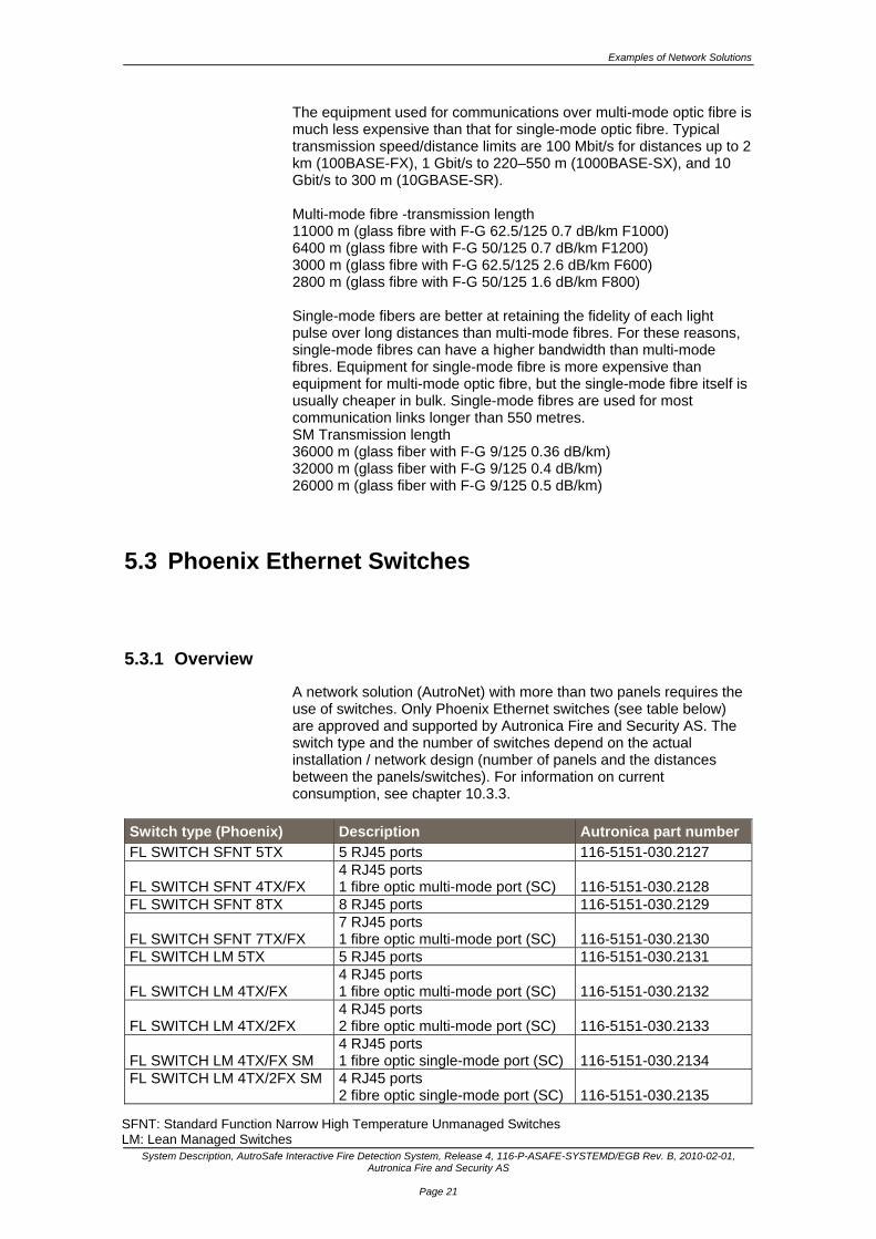
A network solution (AutroNet) with more than two panels requires the use of switches. Only Phoenix Ethernet switches (see table below) are approved and supported by Autronica Fire and Security AS. The switch type and the number of switches depend on the actual installation / network design (number of panels and the distances between the panels/switches). For information on current consumption, see chapter 10.3.3.
Switch type (Phoenix) Description Autronica part number FL SWITCH SFNT 5TX 5 RJ45 ports 116-5151-030.2127
FL SWITCH SFNT 4TX/FX 4 RJ45 ports 1 fibre optic multi-mode port (SC) 116-5151-030.2128
FL SWITCH SFNT 8TX 8 RJ45 ports 116-5151-030.2129
FL SWITCH SFNT 7TX/FX 7 RJ45 ports 1 fibre optic multi-mode port (SC) 116-5151-030.2130
FL SWITCH LM 5TX 5 RJ45 ports 116-5151-030.2131
FL SWITCH LM 4TX/FX 4 RJ45 ports 1 fibre optic multi-mode port (SC) 116-5151-030.2132
FL SWITCH LM 4TX/2FX 4 RJ45 ports 2 fibre optic multi-mode port (SC) 116-5151-030.2133
FL SWITCH LM 4TX/FX SM 4 RJ45 ports 1 fibre optic single-mode port (SC) 116-5151-030.2134
FL SWITCH LM 4TX/2FX SM 4 RJ45 ports 2 fibre optic single-mode port (SC) 116-5151-030.2135
SFNT: Standard Function Narrow High Temperature Unmanaged Switches LM: Lean Managed Switches
Examples of Network Solutions
System Description, AutroSafe Interactive Fire Detection System, Release 4, 116-P-ASAFE-SYSTEMD/EGB Rev. B, 2010-02-01, Autronica Fire and Security AS
Page 22
5.3.2 Twisted Pair
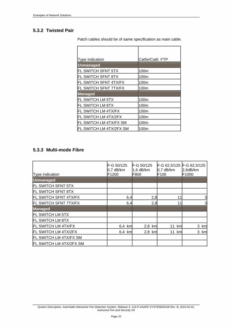
Patch cables should be of same specification as main cable.
Type indication Cat5e/Cat6 FTP
Unmanaged
FL SWITCH SFNT 5TX 100m
FL SWITCH SFNT 8TX 100m
FL SWITCH SFNT 4TX/FX 100m
FL SWITCH SFNT 7TX/FX 100m
Managed
FL SWITCH LM 5TX 100m
FL SWITCH LM 8TX 100m
FL SWITCH LM 4TX/FX 100m
FL SWITCH LM 4TX/2FX 100m
FL SWITCH LM 4TX/FX SM 100m
FL SWITCH LM 4TX/2FX SM 100m
5.3.3 Multi-mode Fibre
Type indication
F-G 50/125 0,7 dB/km F1200
F-G 50/125 1,6 dB/km F800
F-G 62,5/125 0,7 dB/km F100
F-G 62,5/125 2,6dB/km F1000
Unmanaged
FL SWITCH SFNT 5TX
FL SWITCH SFNT 8TX
FL SWITCH SFNT 4TX/FX 6,4 2,8 11 3
FL SWITCH SFNT 7TX/FX 6,4 2,8 11 3
Managed
FL SWITCH LM 5TX
FL SWITCH LM 8TX
FL SWITCH LM 4TX/FX 6,4 km 2,8 km 11 km 3 km
FL SWITCH LM 4TX/2FX 6,4 km 2,8 km 11 km 3 km
FL SWITCH LM 4TX/FX SM
FL SWITCH LM 4TX/2FX SM
Examples of Network Solutions
System Description, AutroSafe Interactive Fire Detection System, Release 4, 116-P-ASAFE-SYSTEMD/EGB Rev. B, 2010-02-01, Autronica Fire and Security AS
Page 23
5.3.4 Single-mode Fibre
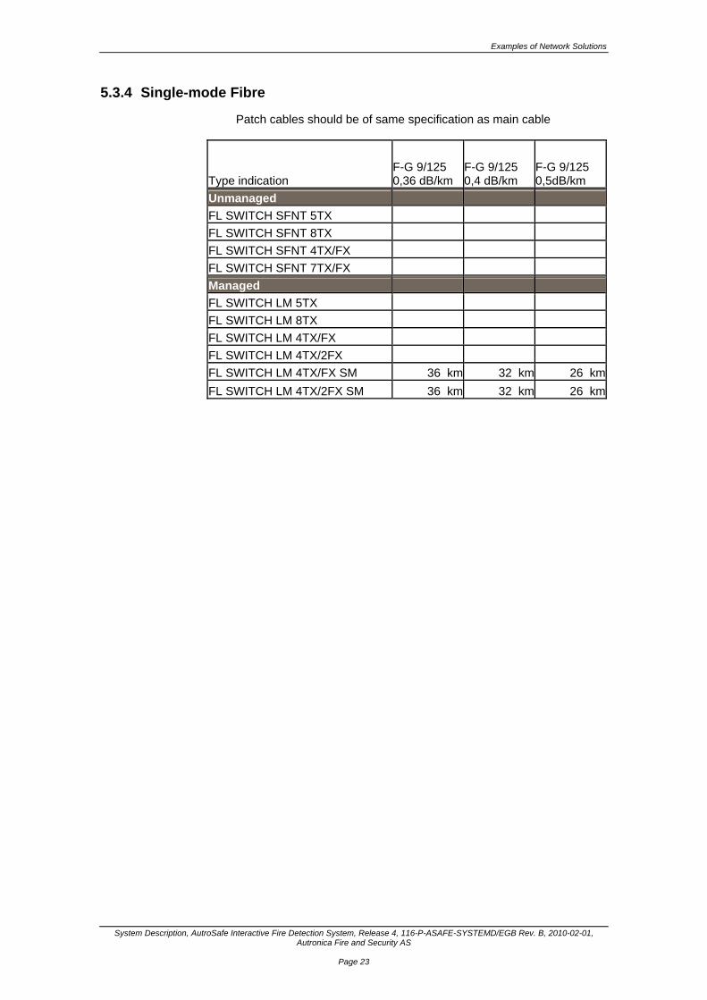
Patch cables should be of same specification as main cable
Type indication F-G 9/125 0,36 dB/km
F-G 9/125 0,4 dB/km
F-G 9/125 0,5dB/km
Unmanaged
FL SWITCH SFNT 5TX
FL SWITCH SFNT 8TX
FL SWITCH SFNT 4TX/FX
FL SWITCH SFNT 7TX/FX
Managed
FL SWITCH LM 5TX
FL SWITCH LM 8TX
FL SWITCH LM 4TX/FX
FL SWITCH LM 4TX/2FX
FL SWITCH LM 4TX/FX SM 36 km 32 km 26 km
FL SWITCH LM 4TX/2FX SM 36 km 32 km 26 km
Examples of Network Solutions
System Description, AutroSafe Interactive Fire Detection System, Release 4, 116-P-ASAFE-SYSTEMD/EGB Rev. B, 2010-02-01, Autronica Fire and Security AS
Page 24
5.4 Network Solution – Example 1
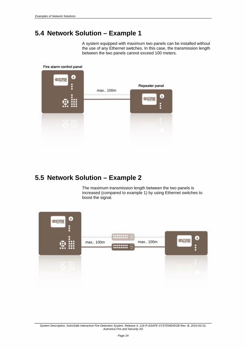
A system equipped with maximum two panels can be installed without the use of any Ethernet switches. In this case, the transmission length between the two panels cannot exceed 100 meters.
5.5 Network Solution – Example 2
The maximum transmission length between the two panels is increased (compared to example 1) by using Ethernet switches to boost the signal.
max.. 100m
max.. 100m max.. 100m

Examples of Network Solutions
System Description, AutroSafe Interactive Fire Detection System, Release 4, 116-P-ASAFE-SYSTEMD/EGB Rev. B, 2010-02-01, Autronica Fire and Security AS
Page 25
5.6 Network Solution – Example 3
A simple network system. The transmission length between the panels and an Ethernet switch does not exceed 100 meters.
5.7 Network Solution – Example 4
The simplest Ethernet switch is equipped with five Tx ports. The switch allows five connections, for example, five panels can be included in a system.

Examples of Network Solutions
System Description, AutroSafe Interactive Fire Detection System, Release 4, 116-P-ASAFE-SYSTEMD/EGB Rev. B, 2010-02-01, Autronica Fire and Security AS
Page 26
5.8 Network Solution – Example 5
If the transmission length between two Ethernet switches exceeds 100 meters, a fibre optic cable can be used to achieve longer distances. Multi-mode optic fibre is a type of optic fibre mostly used for communication over shorter distances, such as within a building. An Ethernet switch equipped with a multi-mode fibre optic port is required.

Examples of Network Solutions
System Description, AutroSafe Interactive Fire Detection System, Release 4, 116-P-ASAFE-SYSTEMD/EGB Rev. B, 2010-02-01, Autronica Fire and Security AS
Page 27
5.9 Network Solution – Example 6
If the transmission length between two Ethernet switches exceeds 100 meters, a fibre optic cable can be used to achieve longer distances. Single-mode fibers are mostly used for communication links longer than 1000 metres.

Examples of Network Solutions
System Description, AutroSafe Interactive Fire Detection System, Release 4, 116-P-ASAFE-SYSTEMD/EGB Rev. B, 2010-02-01, Autronica Fire and Security AS
Page 28
5.10 Network Solution – Example 7
All AutroSafe panels within a system are linked together using an internal Ethernet network. The AutroSafe system uses the same network to communicate with AutroMaster ISEMS (Integrated Safety and Emergency Management System).
5.11 Network Solution – Example 8
By using a single (two for redundancy) Ethernet switch, up to eight AutroSafe panels can be linked together making one system.
Internal Modules
System Description, AutroSafe Interactive Fire Detection System, Release 4, 116-P-ASAFE-SYSTEMD/EGB Rev. B, 2010-02-01, Autronica Fire and Security AS
Page 29
6. Internal Modules
6.1 Module Capacity inside the Fire Alarm Control Panel and Controller
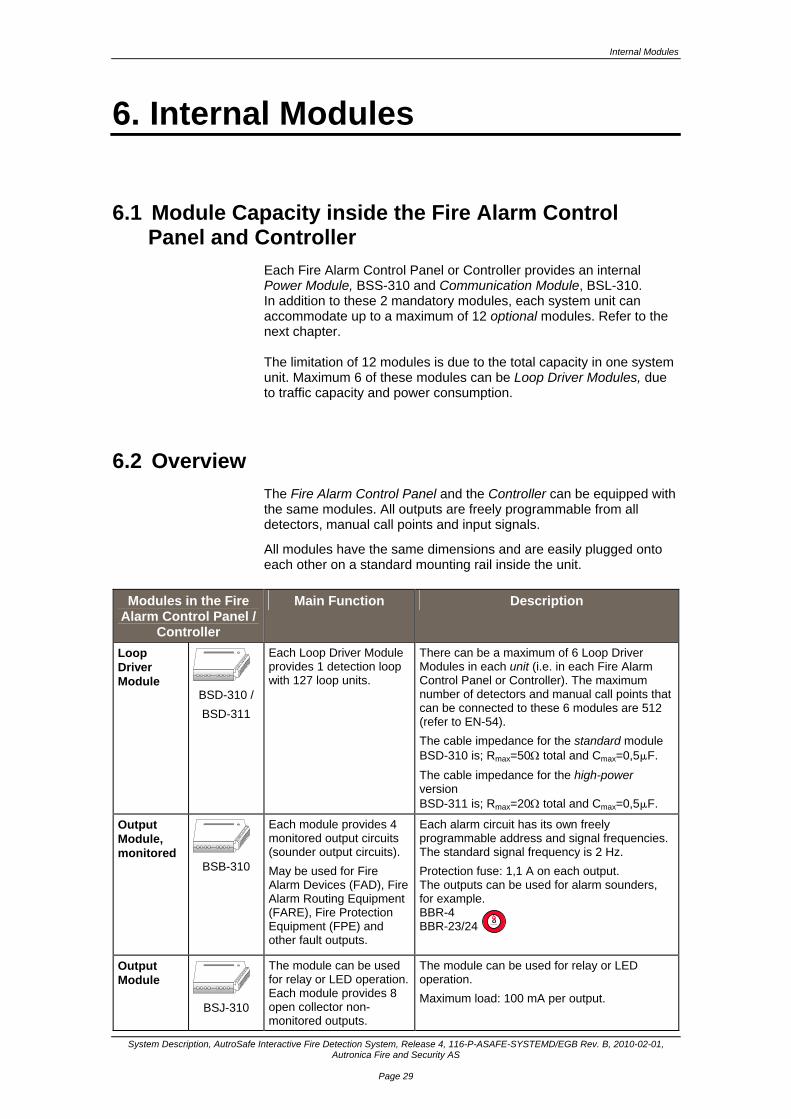
Each Fire Alarm Control Panel or Controller provides an internal Power Module, BSS-310 and Communication Module, BSL-310. In addition to these 2 mandatory modules, each system unit can accommodate up to a maximum of 12 optional modules. Refer to the next chapter. The limitation of 12 modules is due to the total capacity in one system unit. Maximum 6 of these modules can be Loop Driver Modules, due to traffic capacity and power consumption.
6.2 Overview
The Fire Alarm Control Panel and the Controller can be equipped with the same modules. All outputs are freely programmable from all detectors, manual call points and input signals.
All modules have the same dimensions and are easily plugged onto each other on a standard mounting rail inside the unit.
Modules in the Fire Alarm Control Panel /
Controller
Main Function Description
Loop Driver Module
BSD-310 /
BSD-311
Each Loop Driver Module provides 1 detection loop with 127 loop units.
There can be a maximum of 6 Loop Driver Modules in each unit (i.e. in each Fire Alarm Control Panel or Controller). The maximum number of detectors and manual call points that can be connected to these 6 modules are 512 (refer to EN-54).
The cable impedance for the standard module BSD-310 is; Rmax=50 total and Cmax=0,5F.
The cable impedance for the high-power version BSD-311 is; Rmax=20 total and Cmax=0,5F.
Output Module, monitored
BSB-310
Each module provides 4 monitored output circuits (sounder output circuits).
May be used for Fire Alarm Devices (FAD), Fire Alarm Routing Equipment (FARE), Fire Protection Equipment (FPE) and other fault outputs.
Each alarm circuit has its own freely programmable address and signal frequencies. The standard signal frequency is 2 Hz.
Protection fuse: 1,1 A on each output. The outputs can be used for alarm sounders, for example. BBR-4 BBR-23/24
Output Module
BSJ-310
The module can be used for relay or LED operation.Each module provides 8 open collector non-monitored outputs.
The module can be used for relay or LED operation.
Maximum load: 100 mA per output.
Autronica

Internal Modules
System Description, AutroSafe Interactive Fire Detection System, Release 4, 116-P-ASAFE-SYSTEMD/EGB Rev. B, 2010-02-01, Autronica Fire and Security AS
Page 30
Modules in the Fire Alarm Control Panel /
Controller
Main Function Description
Input Module, monitored
BSE-310
Each module provides 4 monitored inputs.
Monitor resistance: 2 k Alarm resistance: 500 - 1k May be used for Digital Input Devices (contacts) and other controlling inputs.
Input Module
BSE-320
Each module provides 8 non-monitored and galvanic isolated inputs.
May be used for Digital Input Devices (contacts) and other controlling inputs.
Communi-cation Module
BSL-310
The module serves as an interface for the common internal communication line between the I/O modules.
Always mounted in the Fire Alarm Control Panel and Controller.
RS-232 interface with hand-shake. Galvanic isolated from the internal circuitry. Built-in battery monitoring. Control outputs for activation of charger/battery. Earth fault monitoring.
Power Module
BSS-310
The module provides 24V and 5V to the I/O modules.
Always mounted in the Fire Alarm Control Panel and Controller.
Two green indicators; Right green indicator - the presence of 24V Left green indicator - the presence of 5V
Conven-tional Loop Interface
BNB-330 (BN-330*)
BNB-330 is a modular interface unit designed to monitor conventional fire detectors of the current increase type and to convey their status to the AutroSafe fire panel. *Variant: The BN-330 unit consists of a BNB-330 module mounted on a DIN-rail inside a PCM-box.
The conventional detectors are connected to a two-wire sub loop. The sub loop is monitored for broken line by an end-of line unit BNY-330. As default a short circuit of the sub loop will give a fault warning, but the unit may be configured to give an alarm instead.
The module version BNB-330 is to be mounted on a DIN-rail onto other internal modules inside the Fire Alarm Control Panel / Controller, where 24VDC power is supplied.
*The BN-330 unit requires separate 24VDC. Conforms to IP-67.
BS-100 Loop Interface
BSD-330
The BS-100 Loop Interface, BSD-330 is used as an interface between the AutroSafe detector loop protocol and BS-100 loop protocol. The interface makes it possible to connect BS-panel type detectors to the AutroSafe system, including detectors used in systems BS-3, BS-30, BS-60, BS-80, BS-90 and BS-100.
In cases where one, two or three BS-100 loops are to be connected to an AutroSafe Panel, the Power Module BSS-310 has enough power to feed the BSD-330 modules.
If more than three modules are used, BSS-310A must be installed instead of BSS-310; this allows up to eight BSD-330 modules to be installed in the panel.

Loop Units
System Description, AutroSafe Interactive Fire Detection System, Release 4, 116-P-ASAFE-SYSTEMD/EGB Rev. B, 2010-02-01, Autronica Fire and Security AS
Page 31
7. Loop Units The AutroSafe System offers a wide range of fire alarm detectors, manual call points and input/output units, with or without the Self-Verifying Function (SV-function). The system offers the choice of the following three main series: Series 200, standard interactive addressable units. Series 300 with SelfVerify, interactive addressable units. Series 500 with SelfVerify, interactive addressable units designed
for use in heavy-duty applications and hazardous areas. The system also offers Ex ia-approved versions intended for high-risk applications. These units are marked with the suffix /Ex. Smoke detector series S comprise special high sensitive smoke detectors Both input and input/output units are also available with the SV-function. Input units can also be delivered in series 500 and 500/Ex.
Detectors on the Detection Loop
Application / Main Function
Description
MultiSensors
BH-220 BH-320 BH-520
BH-520/Ex
Typical applications are, for example, in industrial, maritime and off-shore installations where there is a potential flaming and smouldering fire hazard.
For detection of smoke and rising temperature.
Combines scattered light measurement in the detector chamber with temperature measurement by means of a thermistor.
Comprises a built-in alarm indicator (LED).
Short circuit isolator in each detector*.
Protection degree IP-44D.
Optical Smoke Detectors
BH-200 BH-300 BH-500
BH-500/Ex
For detection of combustion gases mainly consisting of visible (large) particles.
Measurement of scattered infra red light in a measuring chamber. Short circuit isolator in each detector*.
Built-in thermistor for registrating of temperature where the detector is installed.
Comprises a built-in alarm indicator (LED).
Protection degree IP-44D.
Heat Detectors
BD-200 BD-300 BD-500
BD-500/Ex
Used in areas where smoke detectors can not be used due to possible false/unwanted alarm problems.
Grade 1 detectors.
Comprises a built-in alarm indicator (LED).
Short circuit isolator in each detector*.
Series 200, 300, 500: IP-44D
High Sensitive Smoke Detectors
Series S
High sensitive smoke detectors (S-variants).
The system offers these S-variants in series 500, 520 and Ex-approved versions.
Short circuit isolator in each detector*.
Protection degree IP-44D.
A conduit box (BWP-100) for watertight cable entry is available.
* Each individual detector has a built-in short-circuit isolator. In the event of a short-circuit in the detector cable, the short-circuit location will be isolated as the short-circuit isolator will be activated in the detectors on either side.
Loop Units
System Description, AutroSafe Interactive Fire Detection System, Release 4, 116-P-ASAFE-SYSTEMD/EGB Rev. B, 2010-02-01, Autronica Fire and Security AS
Page 32
Other units on the Detection Loop
Application / Main Function
Description
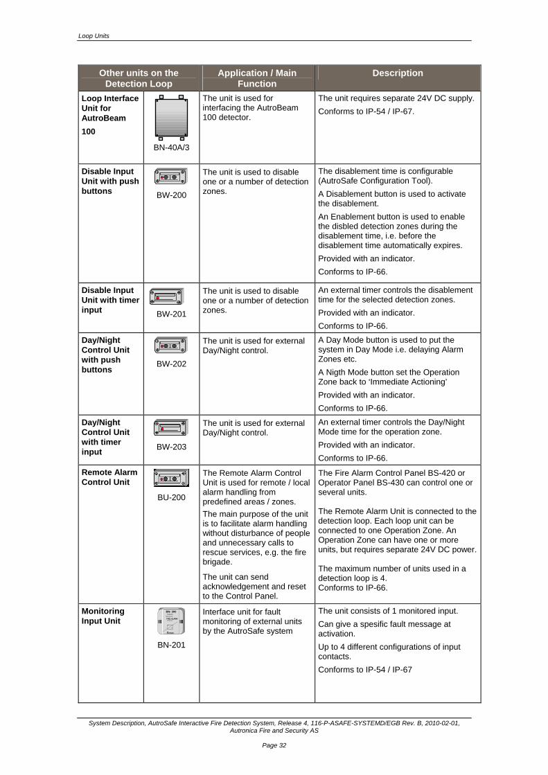
Loop Interface Unit for AutroBeam
100
BN-40A/3
The unit is used for interfacing the AutroBeam 100 detector.
The unit requires separate 24V DC supply.
Conforms to IP-54 / IP-67.
Disable Input Unit with push buttons
BW-200
The unit is used to disable one or a number of detection zones.
The disablement time is configurable (AutroSafe Configuration Tool).
A Disablement button is used to activate the disablement.
An Enablement button is used to enable the disbled detection zones during the disablement time, i.e. before the disablement time automatically expires.
Provided with an indicator.
Conforms to IP-66.
Disable Input Unit with timer input BW-201
The unit is used to disable one or a number of detection zones.
An external timer controls the disablement time for the selected detection zones.
Provided with an indicator.
Conforms to IP-66.
Day/Night Control Unit with push buttons
BW-202
The unit is used for external Day/Night control.
A Day Mode button is used to put the system in Day Mode i.e. delaying Alarm Zones etc.
A Nigth Mode button set the Operation Zone back to ‘Immediate Actioning’
Provided with an indicator.
Conforms to IP-66.
Day/Night Control Unit with timer input
BW-203
The unit is used for external Day/Night control.
An external timer controls the Day/Night Mode time for the operation zone.
Provided with an indicator.
Conforms to IP-66.
Remote Alarm Control Unit
BU-200
The Remote Alarm Control Unit is used for remote / local alarm handling from predefined areas / zones.
The main purpose of the unit is to facilitate alarm handling without disturbance of people and unnecessary calls to rescue services, e.g. the fire brigade.
The unit can send acknowledgement and reset to the Control Panel.
The Fire Alarm Control Panel BS-420 or Operator Panel BS-430 can control one or several units. The Remote Alarm Unit is connected to the detection loop. Each loop unit can be connected to one Operation Zone. An Operation Zone can have one or more units, but requires separate 24V DC power. The maximum number of units used in a detection loop is 4. Conforms to IP-66.
Monitoring Input Unit
BN- 300 BRANNALARM
Tilpasningsenhet
FIRE ALARM Interface unit
Nr.
No.
BN-201
Interface unit for fault monitoring of external units by the AutroSafe system
The unit consists of 1 monitored input.
Can give a spesific fault message at activation.
Up to 4 different configurations of input contacts.
Conforms to IP-54 / IP-67
Loop Units
System Description, AutroSafe Interactive Fire Detection System, Release 4, 116-P-ASAFE-SYSTEMD/EGB Rev. B, 2010-02-01, Autronica Fire and Security AS
Page 33
Other units on the Detection Loop
Application / Main Function
Description
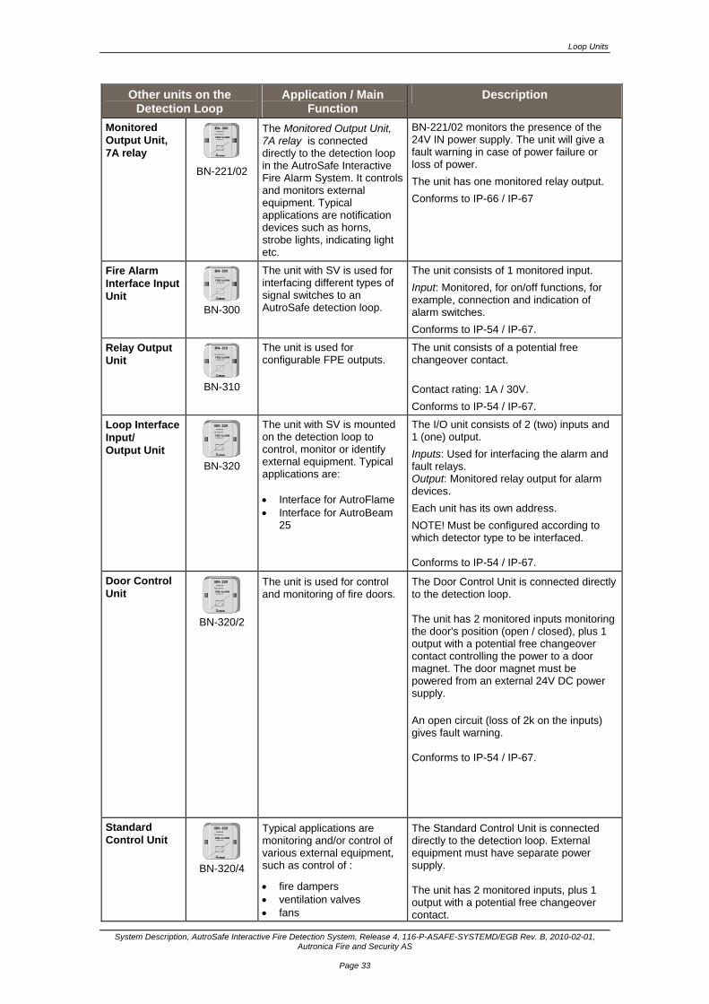
Monitored Output Unit, 7A relay
BN- 300 BRANNALARM
Tilpasningsenhet
FIRE ALARM Interface unit
Nr.
No.
BN-221/02
The Monitored Output Unit, 7A relay is connected directly to the detection loop in the AutroSafe Interactive Fire Alarm System. It controls and monitors external equipment. Typical applications are notification devices such as horns, strobe lights, indicating light etc.
BN-221/02 monitors the presence of the 24V IN power supply. The unit will give a fault warning in case of power failure or loss of power.
The unit has one monitored relay output.
Conforms to IP-66 / IP-67
Fire Alarm Interface Input Unit
BN- 300
Tilpasningsenhet
FIRE ALARMInterface unit
BN-300
The unit with SV is used for interfacing different types of signal switches to an AutroSafe detection loop.
The unit consists of 1 monitored input.
Input: Monitored, for on/off functions, for example, connection and indication of alarm switches.
Conforms to IP-54 / IP-67.
Relay Output Unit
BN- 310
Tilpasningsenhet
FIRE ALARMInterface unit
BN-310
The unit is used for configurable FPE outputs.
The unit consists of a potential free changeover contact.
Contact rating: 1A / 30V.
Conforms to IP-54 / IP-67.
Loop Interface Input/ Output Unit
BN- 320 BRANNALARM
Tilpasningsenhet
FIRE ALARM Interface unit
Nr.
No.
BN-320
The unit with SV is mounted on the detection loop to control, monitor or identify external equipment. Typical applications are: Interface for AutroFlame Interface for AutroBeam
25
The I/O unit consists of 2 (two) inputs and 1 (one) output.
Inputs: Used for interfacing the alarm and fault relays. Output: Monitored relay output for alarm devices.
Each unit has its own address.
NOTE! Must be configured according to which detector type to be interfaced. Conforms to IP-54 / IP-67.
Door Control Unit
BN- 320 BRANNALARM
Tilpasningsenhet
FIRE ALARM Interface unit
Nr.
No.
BN-320/2
The unit is used for control and monitoring of fire doors.
The Door Control Unit is connected directly to the detection loop. The unit has 2 monitored inputs monitoring the door's position (open / closed), plus 1 output with a potential free changeover contact controlling the power to a door magnet. The door magnet must be powered from an external 24V DC power supply. An open circuit (loss of 2k on the inputs) gives fault warning. Conforms to IP-54 / IP-67.
Standard Control Unit
BN- 320 BRANNALARM
Tilpasningsenhet
FIRE ALARM Interface unit
Nr.
No.
BN-320/4
Typical applications are monitoring and/or control of various external equipment, such as control of :
fire dampers ventilation valves fans
The Standard Control Unit is connected directly to the detection loop. External equipment must have separate power supply. The unit has 2 monitored inputs, plus 1 output with a potential free changeover contact.
Loop Units
System Description, AutroSafe Interactive Fire Detection System, Release 4, 116-P-ASAFE-SYSTEMD/EGB Rev. B, 2010-02-01, Autronica Fire and Security AS
Page 34
Other units on the Detection Loop
Application / Main Function
Description
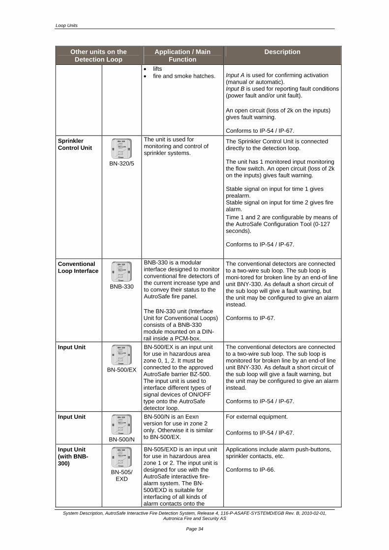
lifts fire and smoke hatches.
Input A is used for confirming activation (manual or automatic). Input B is used for reporting fault conditions (power fault and/or unit fault). An open circuit (loss of 2k on the inputs) gives fault warning. Conforms to IP-54 / IP-67.
Sprinkler Control Unit
BN- 320 BRANNALARM
Tilpasningsenhet
FIRE ALARM Interface unit
Nr.
No.
BN-320/5
The unit is used for monitoring and control of sprinkler systems.
The Sprinkler Control Unit is connected directly to the detection loop. The unit has 1 monitored input monitoring the flow switch. An open circuit (loss of 2k on the inputs) gives fault warning. Stable signal on input for time 1 gives prealarm. Stable signal on input for time 2 gives fire alarm. Time 1 and 2 are configurable by means of the AutroSafe Configuration Tool (0-127 seconds). Conforms to IP-54 / IP-67.
Conventional Loop Interface
BN- 320 BRANNALARM
Tilpasningsenhet
FIRE ALARM Interface unit
Nr.
No.
BNB-330
BNB-330 is a modular interface designed to monitor conventional fire detectors of the current increase type and to convey their status to the AutroSafe fire panel. The BN-330 unit (Interface Unit for Conventional Loops) consists of a BNB-330 module mounted on a DIN-rail inside a PCM-box.
The conventional detectors are connected to a two-wire sub loop. The sub loop is moni-tored for broken line by an end-of line unit BNY-330. As default a short circuit of the sub loop will give a fault warning, but the unit may be configured to give an alarm instead. Conforms to IP-67.
Input Unit BN- 320 BRANNALARM
Tilpasningsenhet
FIRE ALARM Interface unit
Nr.
No.
BN-500/EX
BN-500/EX is an input unit for use in hazardous area zone 0, 1, 2. It must be connected to the approved AutroSafe barrier BZ-500. The input unit is used to interface different types of signal devices of ON/OFF type onto the AutroSafe detector loop.
The conventional detectors are connected to a two-wire sub loop. The sub loop is monitored for broken line by an end-of line unit BNY-330. As default a short circuit of the sub loop will give a fault warning, but the unit may be configured to give an alarm instead. Conforms to IP-54 / IP-67.
Input Unit BN- 320 BRANNALARM
Tilpasningsenhet
FIRE ALARM Interface unit
Nr.
No.
BN-500/N
BN-500/N is an Eexn version for use in zone 2 only. Otherwise it is similar to BN-500/EX.
For external equipment.
Conforms to IP-54 / IP-67.
Input Unit (with BNB-300)
BN- 320 BRANNALARM
Tilpasningsenhet
FIRE ALARM Interface unit
Nr.
No.
BN-505/
EXD
BN-505/EXD is an input unit for use in hazardous area zone 1 or 2. The input unit is designed for use with the AutroSafe interactive fire-alarm system. The BN-500/EXD is suitable for interfacing of all kinds of alarm contacts onto the
Applications include alarm push-buttons, sprinkler contacts, etc. Conforms to IP-66.

Loop Units
System Description, AutroSafe Interactive Fire Detection System, Release 4, 116-P-ASAFE-SYSTEMD/EGB Rev. B, 2010-02-01, Autronica Fire and Security AS
Page 35
Other units on the Detection Loop
Application / Main Function
Description
AutroSafe system. It is often used as a general interface for EXE approved call points etc. in order to avoid costly approvals for each type of equipment.
Socket
Sounder
BBR-110
Detector base with addressable sounder intended for use with AutroSafe detectors.
Powered from the detection loop.
Has a 86-decibel sound output at 1 meter.
With BSD-310 up to 20 sounders can be used on one detection loop with 99 points. With BSD-311 a maximum of 40 sounders with a total of 99 loopunits can be used.
Conforms to IP-42.
Electronic Sounder
BBR-200
Electronic Sounder with address / interface board inside.
Connected directly to the detection loop.
Requires no separate power supply.
Powered from the detection loop. No external power supply required.
Current consumption: 5 mA at 24 VDC.
The maximum number of electronic sounders on a detection loop depends on the configuration of the detection loop.
Conforms to IP-42.
Manual Call Point P RE SS H ER ETRYK K HER
KNUS GLASSE T
BREAK GLASS
BF-300 /
BF-300V2
Manual Call Point used to manually initiate alarms.
Series 300: Manual Call Points with LED indication and SV-function. Conforms to IP-44D.
Manual Call Point P RE SS H ER ETRYK K HER
KNUS GLASSE T
BREAK GLASS
BF-300M
BF-300M/N
Manual Call Point used to manually initiate alarms.
Designed specially for maritime application and installation with open cabling.
BF-300M/N is for zone 2 only.
Series 300: Manual Call Points with LED indication and SV-function. Conforms to IP-44D.
Delivered with a metal surface mounting box with epoxy powder coating.
Four 20 mm square cable entry holes are provided.
Manual Call Point
PR ES S H E R ETR Y K K H E RKNUS GLASSET
BREAK GLASS
0 7 04
BF-500/Ex BF-500/N
Manual Call Point used to manually initiate alarms.
Ex-approved for use in hazardous areas.
BF-500/N is for zone 2 only.
Manual Call Point with SV-function, but without LED. Conforms to IP-44D.
Manual Call Point
BF-501
Manual Call Point used to manually initiate alarms.
For outdoor use.
Manual Call Point with SV-function, but without LED.
Conforms to IP-66..
Two 20 mm square cable entry holes are provided.
Manual Call Point
BF-501/Ex BF-501/N
Manual Call Point used to manually initiate alarms.
Ex-approved for use in hazardous areas.
For outdoor use.
BF-501/N is for zone 2 only.
Same function as series 500, but with protection grade IP-66..
Two 20 square mm cable entry holes are provided.
Without LED.
Manual Call Points for special purposes
Manual Call Points used to manually initiate alarms.
In addition to the types listed above in this table, Autronica Fire and Security AS offers other types of manual call points for special purposes. Refer to Product Catalogue.
Loop Units
System Description, AutroSafe Interactive Fire Detection System, Release 4, 116-P-ASAFE-SYSTEMD/EGB Rev. B, 2010-02-01, Autronica Fire and Security AS
Page 36
Other units on the Detection Loop
Application / Main Function
Description
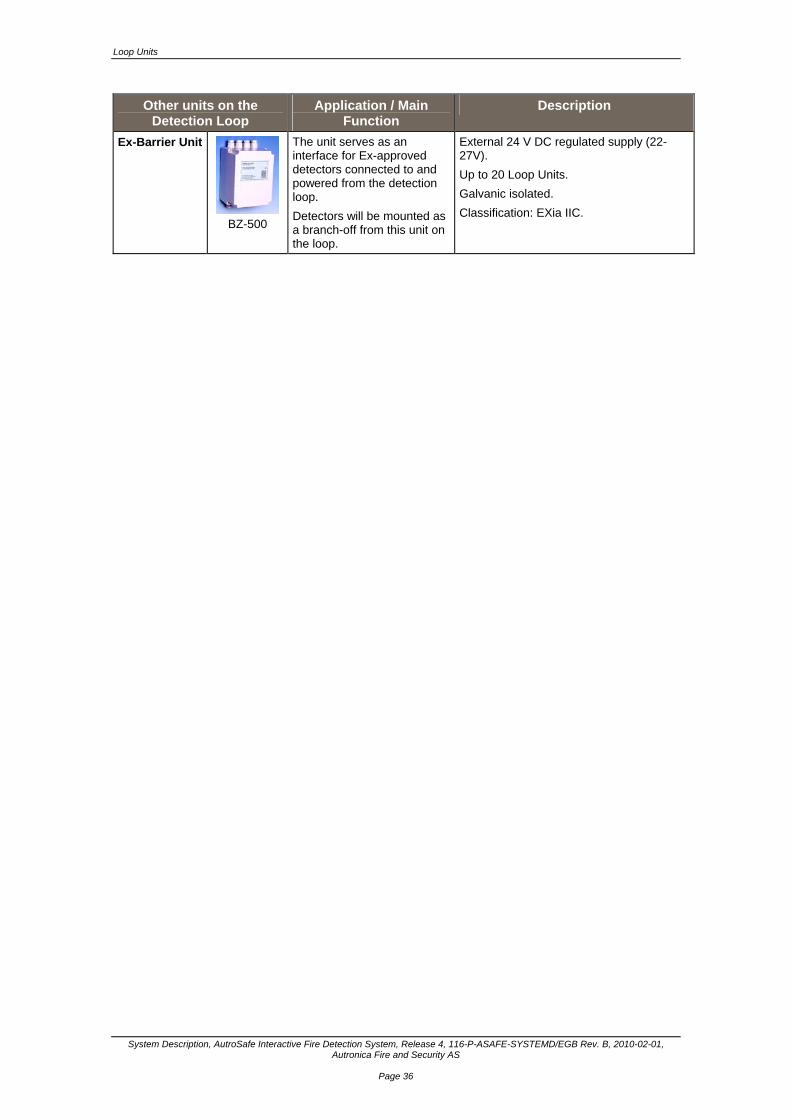
Ex-Barrier Unit
BZ-500
The unit serves as an interface for Ex-approved detectors connected to and powered from the detection loop.
Detectors will be mounted as a branch-off from this unit on the loop.
External 24 V DC regulated supply (22-27V).
Up to 20 Loop Units.
Galvanic isolated.
Classification: EXia IIC.
Detection Loops
System Description, AutroSafe Interactive Fire Detection System, Release 4, 116-P-ASAFE-SYSTEMD/EGB Rev. B, 2010-02-01, Autronica Fire and Security AS
Page 37
8. Detection Loops
8.1 Description
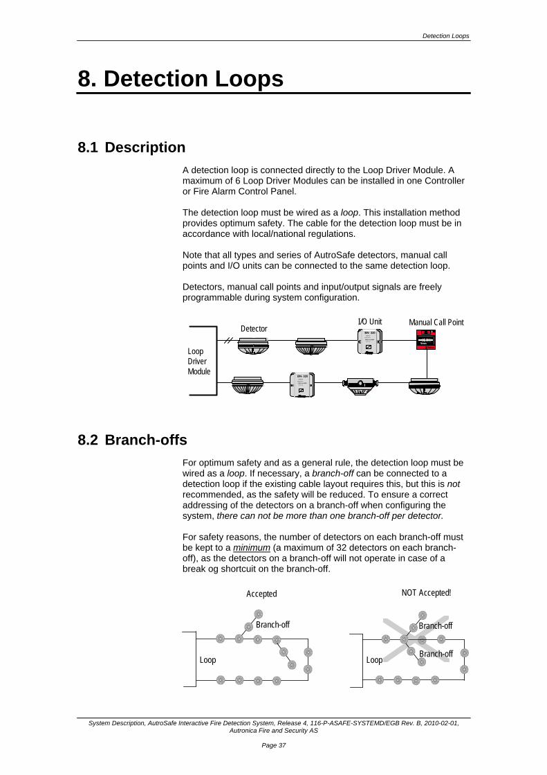
A detection loop is connected directly to the Loop Driver Module. A maximum of 6 Loop Driver Modules can be installed in one Controller or Fire Alarm Control Panel. The detection loop must be wired as a loop. This installation method provides optimum safety. The cable for the detection loop must be in accordance with local/national regulations. Note that all types and series of AutroSafe detectors, manual call points and I/O units can be connected to the same detection loop. Detectors, manual call points and input/output signals are freely programmable during system configuration.
PRES S H ER ET RYK K HERKNUS GLAS SE T
BR EAK GLASS
Loop DriverModule
DetectorI/O Unit Manual Call Point
BN- 320BRANNALARM
Tilpasningsenhet
FIRE ALARMInterface unit
Nr.
No.
BN- 320BRANNALARM
Tilpasningsenhet
FIRE ALARMInterface uni t
Nr.
No.
8.2 Branch-offs
For optimum safety and as a general rule, the detection loop must be wired as a loop. If necessary, a branch-off can be connected to a detection loop if the existing cable layout requires this, but this is not recommended, as the safety will be reduced. To ensure a correct addressing of the detectors on a branch-off when configuring the system, there can not be more than one branch-off per detector. For safety reasons, the number of detectors on each branch-off must be kept to a minimum (a maximum of 32 detectors on each branch-off), as the detectors on a branch-off will not operate in case of a break og shortcuit on the branch-off.
Accepted NOT Accepted!
Loop Loop
Branch-off Branch-off
Branch-off
Detection Loops
System Description, AutroSafe Interactive Fire Detection System, Release 4, 116-P-ASAFE-SYSTEMD/EGB Rev. B, 2010-02-01, Autronica Fire and Security AS
Page 38
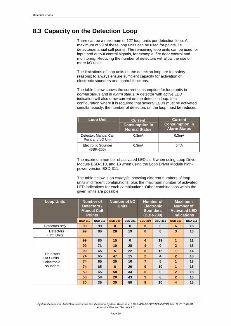
8.3 Capacity on the Detection Loop
There can be a maximum of 127 loop units per detection loop. A maximum of 99 of these loop units can be used for points, i.e. detectors/manual call points. The remaining loop units can be used for input and output control signals, for example, fire door control and monitoring. Reducing the number of detectors will allow the use of more I/O units. The limitations of loop units on the detection loop are for safety reasons; to always ensure sufficient capacity for activation of electronic sounders and control functions. The table below shows the current consumption for loop units in normal status and in alarm status. A detector with active LED indication will also draw current on the detection loop. In a configuration where it is required that several LEDs must be activated simultaneously, the number of detectors on the loop must be reduced.
Loop Unit Current Consumption in Normal Status
Current Consumption in
Alarm Status
Detector, Manual Call Point and I/O Unit
0,3mA 0,3mA
Electronic Sounder (BBR-200)
0,3mA 5mA
The maximum number of activated LEDs is 6 when using Loop Driver Module BSD-310, and 18 when using the Loop Driver Module high-power version BSD-311. The table below is an example, showing different numbers of loop units in different combinations, plus the maximum number of activated LED indications for each combination*. Other combinations within the given limits are possible.
Loop Units
Number of Detectors / Manual Call
Points
Number of I/O Units
Number of Electronic Sounders (BBR-200)
Maximum Number of
Activated LED Indications
BSD-310 BSD-311 BSD-310 BSD-311 BSD-310 BSD-311 BSD-310 BSD-311
Detectors only 99 99 0 0 0 0 6 18
Detectors + I/O Units
99 80 28 19 0 0 3 18
99 80 15 0 4 19 1 11
99 71 10 28 4 0 2 18
99 65 5 22 5 12 1 14
74 65 47 15 2 4 2 18
74 65 20 10 7 5 1 18
74 65 6 20 9 10 1 15
50 65 50 34 5 0 2 18
50 50 20 43 9 6 2 16
30 35 30 50 9 10 4 15
Detectors + I/O Units + electronic sounders
Cable Specifications
System Description, AutroSafe Interactive Fire Detection System, Release 4, 116-P-ASAFE-SYSTEMD/EGB Rev. B, 2010-02-01, Autronica Fire and Security AS
Page 39
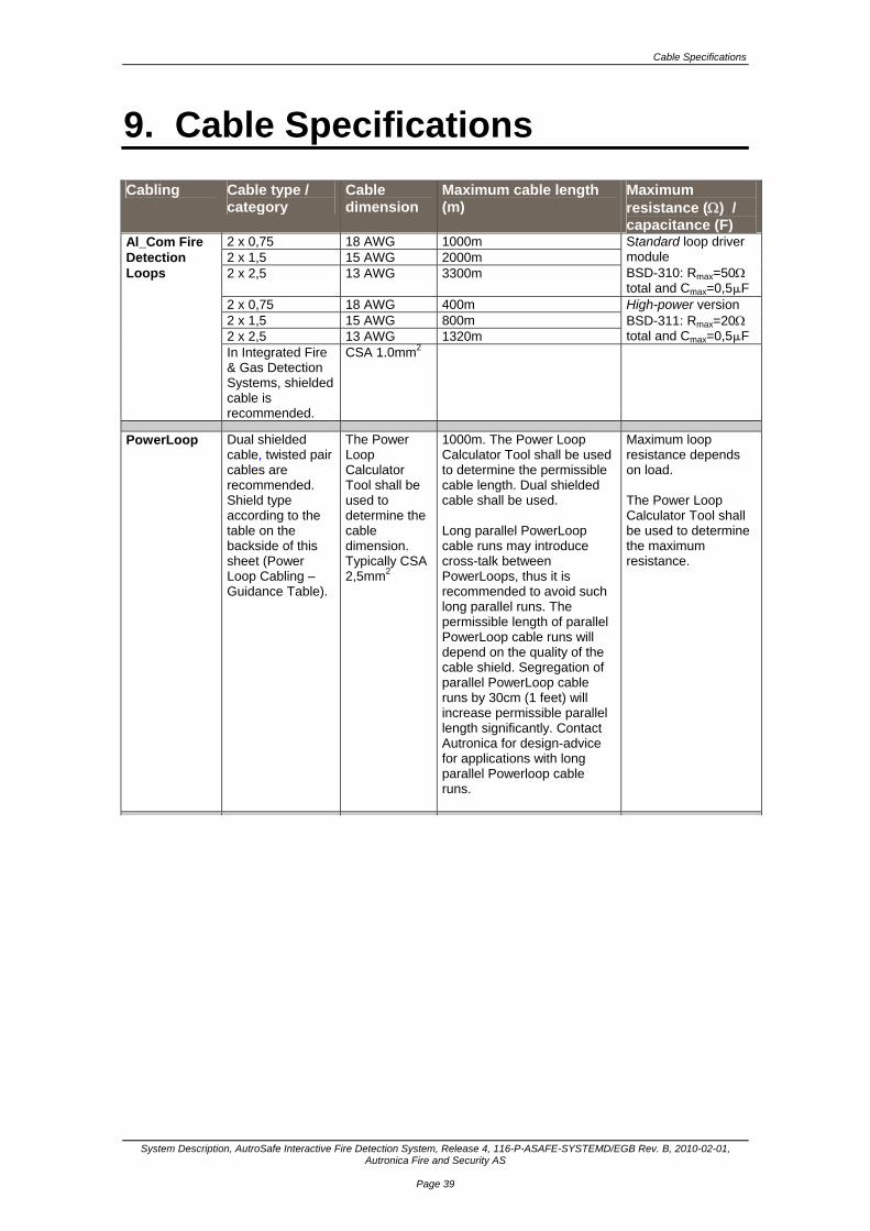
9. Cable Specifications
Cabling Cable type / category
Cable dimension
Maximum cable length (m)
Maximum resistance () / capacitance (F)
2 x 0,75 18 AWG 1000m 2 x 1,5 15 AWG 2000m 2 x 2,5 13 AWG 3300m
Standard loop driver module BSD-310: Rmax=50 total and Cmax=0,5F
2 x 0,75 18 AWG 400m 2 x 1,5 15 AWG 800m 2 x 2,5 13 AWG 1320m
High-power version BSD-311: Rmax=20 total and Cmax=0,5F
Al_Com Fire Detection Loops
In Integrated Fire & Gas Detection Systems, shielded cable is recommended.
CSA 1.0mm2
PowerLoop Dual shielded cable, twisted pair cables are recommended. Shield type according to the table on the backside of this sheet (Power Loop Cabling – Guidance Table).
The Power Loop Calculator Tool shall be used to determine the cable dimension. Typically CSA 2,5mm2
1000m. The Power Loop Calculator Tool shall be used to determine the permissible cable length. Dual shielded cable shall be used. Long parallel PowerLoop cable runs may introduce cross-talk between PowerLoops, thus it is recommended to avoid such long parallel runs. The permissible length of parallel PowerLoop cable runs will depend on the quality of the cable shield. Segregation of parallel PowerLoop cable runs by 30cm (1 feet) will increase permissible parallel length significantly. Contact Autronica for design-advice for applications with long parallel Powerloop cable runs.
Maximum loop resistance depends on load. The Power Loop Calculator Tool shall be used to determine the maximum resistance.
Cable Specifications
System Description, AutroSafe Interactive Fire Detection System, Release 4, 116-P-ASAFE-SYSTEMD/EGB Rev. B, 2010-02-01, Autronica Fire and Security AS
Page 40
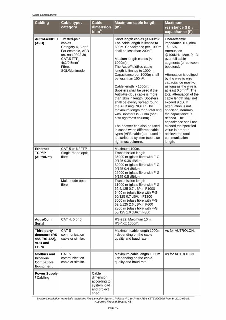
Cabling Cable type / category
Cable dimension(mm2)
Maximum cable length (m)
Maximum resistance () / capacitance (F)
AutroFieldBus (AFB)
Twisted-pair cables. Category 4, 5 or 6 For example, ABB art. no 10892 30 CAT.5 FTP 4x2/0.5mm2
Fibre, SGL/Multimode
Short length cables (< 600m): The cable length is limited to 600m. Capacitance per 1000m shall be less than 200nF. Medium length cables (< 1000m): The AutroFieldBus cable length is limited to 1000m. Capacitance per 1000m shall be less than 100nF. Cable length > 1000m: Boosters shall be used if the AutroFieldBus cable is more than 1km in length. Boosters shall be evenly spread round the AFB ring. NOTE: The maximum length for a total ring with Boosters is 2,8km (see also rightmost column). The booster can also be used in cases when different cable types (AFB cables) are used in a distributed system (see also rightmost column).
Characteristic impedance 100 ohm +/- 15%. Attenuation @100KHz, Max. 9 dB over full cable segments (or between boosters). Attenuation is defined by the wire to wire capacitance mostly, as long as the wire is at least 0.5mm2. The total attenuation of the cable length shall not exceed 9 dB. If attenuation is not specified, normally the capacitance is defined. The capacitance shall not exceed the specified value in order to achieve the total communication length.
CAT 5 or 6 / FTP Maximum 100m. Single-mode optic fibre
Transmission length 36000 m (glass fibre with F-G 9/125 0.36 dB/km 32000 m (glass fibre with F-G 9/125 0.4 dB/km 26000 m (glass fibre with F-G 9/125 0.5 dB/km
Ethernet –TCP/IP (AutroNet)
Multi-mode optic fibre
Transmission length 11000 m (glass fibre with F-G 62.5/125 0.7 dB/km F1000 6400 m (glass fibre with F-G 50/125 0.7 dB/km F1200 3000 m (glass fibre with F-G 62.5/125 2.6 dB/km F600 2800 m (glass fibre with F-G 50/125 1.6 dB/km F800
AutroCom Serial
CAT 4, 5 or 6. RS-232: Maximum 10m. RS-4xx: 1000m.
Third party detectors (RS-485 /RS-422), VDR and ESPA
CAT 5 communication cable or similar.
Maximum cable length 1000m - depending on the cable quality and baud rate.
As for AUTROLON.
Modbus and Profibus Compatible Equipment
CAT 5 communication cable or similar.
Maximum cable length 1000m - depending on the cable quality and baud rate.
As for AUTROLON.
Power Supply / Cabling
Cable dimension according to system load and project spec.

Power Distribution, Calculation and Consumption
System Description, AutroSafe Interactive Fire Detection System, Release 4, 116-P-ASAFE-SYSTEMD/EGB Rev. B, 2010-02-01, Autronica Fire and Security AS
Page 41
10. Power Distribution, Calculation and Consumption
10.1 Introduction
The power supply provides power to AutroSafe, AutroSafe’s existing I/O module stacks, battery monitoring and charging, plus 24 voltage contacts for other external equipment. 2 x 24V outputs of 2A to AutroSafe panel 2 x 24V outputs of 2A to I/O stack 2 x 24V outputs of 2A to third-party equipment 1 input for battery 1 input for battery charger Communication Power control for battery Control signals for battery charger All internal voltage levels are monitored Temperature sensor for compensation of charger voltage
3rd party power outputs
Power Supply
24 VControlsignals
Autro Safe
AFB(Autro-
FieldBus)
24 V
24 V
24 V
Battery
24 V TemperatureContact,24V/2A
Contact,24V/2A
I/O Stack
Interfaces /Connections
Switchesfor I/OStack
Power Distribution, Calculation and Consumption
System Description, AutroSafe Interactive Fire Detection System, Release 4, 116-P-ASAFE-SYSTEMD/EGB Rev. B, 2010-02-01, Autronica Fire and Security AS
Page 42
The Power Cabinet BP-405 supplies a maximum of 5A, of which 3A is available for the fire detection system. 2A is used for the charging and maintenance of the battery. Note that the maximum load for each output (A1, A2, B1, B2, C1, C2) is 2A. Output A supplies 2A and functions as a single output for all Controllers BC-420 and panels (BS-420, BS-430, BU-BV-420). Output C supplies 2A to the internal modules mounted on the rail inside the Controller BC-420 and Fire Alarm Control Panel BS-420. Note that if there is a maximum load from both output A and C, the total load would be 4A, which in this case would exceed the limit of 3A. It is therefore important to calculate the total power consumption for each Power Cabinet BP-405 to ensure that this limit is not exceeded. The example described in the next chapter shows how you can easily find out if the power consumption in a system is within the given limits.
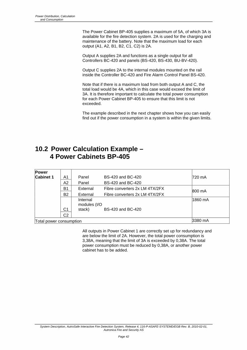
10.2 Power Calculation Example – 4 Power Cabinets BP-405
Power Cabinet 1 A1 Panel BS-420 and BC-420 A2 Panel BS-420 and BC-420
720 mA
B1 External Fibre converters 2x LM 4TX/2FX
B2 External Fibre converters 2x LM 4TX/2FX 800 mA
C1
Internal modules (I/O stack) BS-420 and BC-420
C2
1860 mA
Total power consumption 3380 mA All outputs in Power Cabinet 1 are correctly set up for redundancy and are below the limit of 2A. However, the total power consumption is 3,38A, meaning that the limit of 3A is exceeded by 0,38A. The total power consumption must be reduced by 0,38A, or another power cabinet has to be added.

Power Distribution, Calculation and Consumption
System Description, AutroSafe Interactive Fire Detection System, Release 4, 116-P-ASAFE-SYSTEMD/EGB Rev. B, 2010-02-01, Autronica Fire and Security AS
Page 43
Power Cabinet 2 A1 Panel 2 x BC-420 A2 Panel 2 x BC-420
720 mA
B1 External
B2 External
C1
Internal modules (I/O stack) 2 x BC-420
C2
1860 mA
Total power consumption 2580 mA Power Cabinet 2 is correctly set up, as no outputs exceed the limit of 2A and the total power consumption is 2,58A, i.e. below the limit of 3A. In order to reduce the total power consumption for Power Cabinet 1 to 3A (the limit), one of the fibre converters powered from Power Cabinet 1 can instead be powered from Power Cabinet 2. The total power consumption for Power Cabinet 1 will then be reduced by 400mA to 2980mA (<3A). Both Power Cabinets will now have a total power consumption within the limit of 3A.
Power Cabinet 3 A1 Panel BU-BV-420 A2 Panel BU-BV-420
220 mA
B1 External Various additional external equipment 24V 500 mA
B2 External Equipment that does not require redundancy 750 mA
C1
Internal modules (I/O stack)
C2
Total power consumption 1470 mA A Repeater Panel BU-BV-420 is powered from a Power Cabinet 3. Power Cabinet 3 supplies redundant power to the Repeater Panel BU-BV-420. In addition, it supplies power to equipment that does not require redundant power. If redundancy is not required, power can be supplied from one output (for example, output B1 or B2). Output C1 or C2 cannot be used to other equipment, as this output is shut off 3 seconds during an initialization of the system.
Power Cabinet 4 A1 Panel 1x BC-420 A2 Panel 1x BC-420 and BS-420
680 mA
B1 External Various relays and door magnets
B2 External Various relays and door magnets 2500 mA
C1
Internal modules (I/O stack) BC-420 and BS-420
C2 BC-420 and BS-420
2300 mA
Total power consumption 5480 mA
Power Distribution, Calculation and Consumption
System Description, AutroSafe Interactive Fire Detection System, Release 4, 116-P-ASAFE-SYSTEMD/EGB Rev. B, 2010-02-01, Autronica Fire and Security AS
Page 44
The power distribution from Power Cabinet 4 is not according to legal specifications of the Power Cabinet BP-405.
BS-420 is not supplied with redundant power. Power must also be supplied from output A1.
The power consumption from output C1 and C2 exceeds the limits. The internal modules (I/O stack) draw too much power.
The total power consumption exceeds 3A. Power consumption status: Output A
The power consumption is below the limit (2A), but the BS-420 must have redundant power, and thus must be supplied with power from A1.
Output B More than 2A is supplied to equipment that does not require redundant power. This means that this output can supply a maximum of 4A (2A + 2A).
Output C This connection is not satisfactory as the power consumption is above 2A.
Conclusion: The total power consumption (5480mA) related to the power distribution in Power Cabinet 4 is far too high. More power must be supplied. A separate power supply can be used to supply power to equipment that does not require redundancy. If the power consumption is reduced by 2,5A, power supplied from Power Cabinet 4 will be sufficient, as the power needed is no longer exceeding the total limit of BP-405. Port C is still above 2A and must be reduced either by removing components that are not needed or by using an additional Power Cabinet BP-405.
10.3 Power Consumption
10.3.1 Mains Power
The current consumption at 115V is 3,2A. The current consumption at 230V is 1,6A. The inrush peak current consumption is 35A.
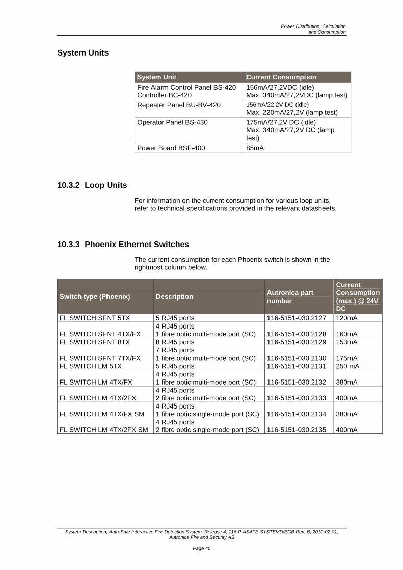
Power Distribution, Calculation and Consumption
System Description, AutroSafe Interactive Fire Detection System, Release 4, 116-P-ASAFE-SYSTEMD/EGB Rev. B, 2010-02-01, Autronica Fire and Security AS
Page 45
System Units
System Unit Current Consumption
Fire Alarm Control Panel BS-420 Controller BC-420
156mA/27,2VDC (idle) Max. 340mA/27,2VDC (lamp test)
Repeater Panel BU-BV-420 156mA/22,2V DC (idle) Max. 220mA/27,2V (lamp test)
Operator Panel BS-430 175mA/27,2V DC (idle) Max. 340mA/27,2V DC (lamp test)
Power Board BSF-400 85mA
10.3.2 Loop Units
For information on the current consumption for various loop units, refer to technical specifications provided in the relevant datasheets.
10.3.3 Phoenix Ethernet Switches
The current consumption for each Phoenix switch is shown in the rightmost column below.
Switch type (Phoenix) Description Autronica part number
Current Consumption (max.) @ 24V DC
FL SWITCH SFNT 5TX 5 RJ45 ports 116-5151-030.2127 120mA
FL SWITCH SFNT 4TX/FX 4 RJ45 ports 1 fibre optic multi-mode port (SC) 116-5151-030.2128 160mA
FL SWITCH SFNT 8TX 8 RJ45 ports 116-5151-030.2129 153mA
FL SWITCH SFNT 7TX/FX 7 RJ45 ports 1 fibre optic multi-mode port (SC) 116-5151-030.2130 175mA
FL SWITCH LM 5TX 5 RJ45 ports 116-5151-030.2131 250 mA
FL SWITCH LM 4TX/FX 4 RJ45 ports 1 fibre optic multi-mode port (SC) 116-5151-030.2132 380mA
FL SWITCH LM 4TX/2FX 4 RJ45 ports 2 fibre optic multi-mode port (SC) 116-5151-030.2133 400mA
FL SWITCH LM 4TX/FX SM 4 RJ45 ports 1 fibre optic single-mode port (SC) 116-5151-030.2134 380mA
FL SWITCH LM 4TX/2FX SM 4 RJ45 ports 2 fibre optic single-mode port (SC) 116-5151-030.2135 400mA

Appendix
System Description, AutroSafe Interactive Fire Detection System, Release 4, 116-P-ASAFE-SYSTEMD/EGB Rev. B, 2010-02-01, Autronica Fire and Security AS
Page 46
11. Appendix
11.1 Zoning Concept
11.1.1 General
To describe the functional hierarchy of the system we use the term "zone". Assigning system components to zones enables hierarchical control from detection to activation of alarm. This hierarchy consists of the following zones: Detection Zone (DZ) Alarm Zone (AZ) Operation Zone (OZ)
Operation Zone
DetectionZone
AlarmZone
Fire Alarm Control PanelsOperator Panels
Information PanelsRepeater Panels
Points(Detectors /ManualCall PointsInputsignals)
Sounders
11.1.2 Detection Zone
A Detection Zone (DZ) is defined as a zone with one or more points (detectors or manual call-points) that logically belong together, determined by geographical/functional parameters (for example, the sales department on the second floor). A point can only be assigned to one detection zone, and can only refer to one specific location in the system (for example, a specific office on the second floor in a building). The Detection Zone will be the trigger to generate outputs to the Alarm Zone.

Appendix
System Description, AutroSafe Interactive Fire Detection System, Release 4, 116-P-ASAFE-SYSTEMD/EGB Rev. B, 2010-02-01, Autronica Fire and Security AS
Page 47
11.1.3 Alarm Zone
An Alarm Zone (AZ) is activated by one or several detection zones. Example: An alarm from one of the devices in DZ3 will activate sounders in AZ1. Within the same alarm zone, alarm sounders give the same audible signal. Geographically associated alarm zones can be defined as neighbour zones, such that these can operate outputs for alarm zones adjacent to the incident.
11.1.4 Operation Zone
An Operation Zone (OZ) defines the scope of an Operator Panel. The operation zone can cover one floor or one building, and is designed to restrict the operators’ sphere of influence on the system as a whole. At least one Fire Alarm Control Panel / Operator Panel should have the overall control of the system. Operation zones on higher levels may encompass several other operation zones. Input / Output units (for example, Door Control Units, Sprinkler Control Units etc.) can be controlled from an Operation Zone. An Operation Zone given these properties and necessary parameter settings is referred to as a Control Operation Zone. Different day / night operation for different areas (i.e. detection zones) requires the use of several Operation Zones / sub-operation zones with different Day / Night Operation. An Operation Zone given these properties and necessary parameter settings is referred to as a Day / Night Operation Zone.
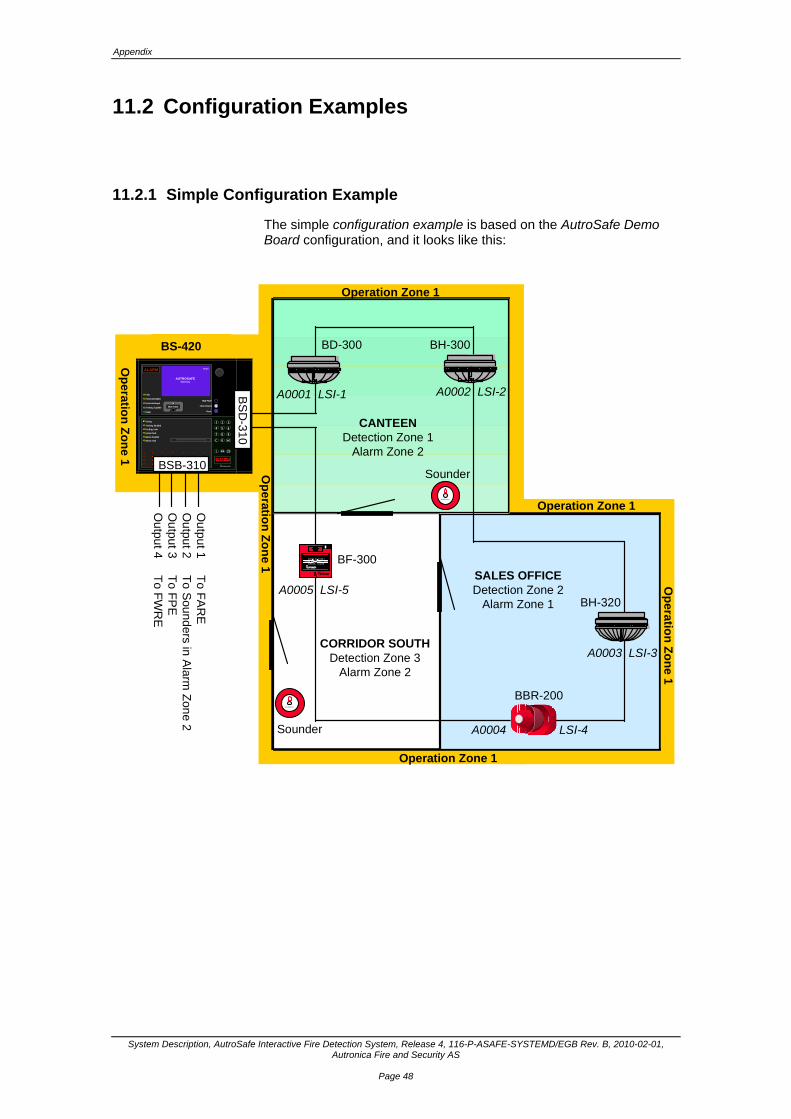
Appendix
System Description, AutroSafe Interactive Fire Detection System, Release 4, 116-P-ASAFE-SYSTEMD/EGB Rev. B, 2010-02-01, Autronica Fire and Security AS
Page 48
11.2 Configuration Examples
11.2.1 Simple Configuration Example
The simple configuration example is based on the AutroSafe Demo Board configuration, and it looks like this:
Operation Zone 1
SALES OFFICEDetection Zone 2
Alarm Zone 1
CORRIDOR SOUTHDetection Zone 3
Alarm Zone 2
BD-300 BH-300
BF-300
BBR-200
BH-320O
utpu
t 1 T
o FA
RE
Ou
tput 2
To S
ound
ers in A
larm Z
one 2
Ou
tput 3
To F
PE
Ou
tput 4
To F
WR
E
Au tronica
Autronica
Sounder
Sounder
Operation Zone 1
Operation Zone 1
Op
eratio
n Z
on
e 1
Op
eratio
n Z
on
e 1
Power
Fire Brig. Signalled
Function Delayed
Function Disabled
0
ALARM
i
C
987
654
321
Mute Panel
Silence Alarms
Reset
More Events
Testing
Fire Brig. Disabled
System Fault
Alarms Disabled
Fire Brig. Fault
Fault
Alarms Fault
AUTROSAFESelfVerify
19:23
CANTEENDetection Zone 1
Alarm Zone 2
A0002 LSI-2
A0003 LSI-3
A0004 LSI-4
A0005 LSI-5
A0001 LSI-1
BS-320
P RE S S H ER ET RYK K HERKNUS G LASSE T
BREAK G LASS
Op
eratio
n Z
on
e 1
BS
D-3
10
BSB-310
BS-420
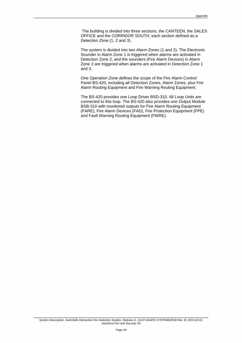
Appendix
System Description, AutroSafe Interactive Fire Detection System, Release 4, 116-P-ASAFE-SYSTEMD/EGB Rev. B, 2010-02-01, Autronica Fire and Security AS
Page 49
The building is divided into three sections, the CANTEEN, the SALES OFFICE and the CORRIDOR SOUTH, each section defined as a Detection Zone (1, 2 and 3). The system is divided into two Alarm Zones (1 and 2). The Electronic Sounder in Alarm Zone 1 is triggered when alarms are activated in Detection Zone 2, and the sounders (Fire Alarm Devices) in Alarm Zone 2 are triggered when alarms are activated in Detection Zone 1 and 3. One Operation Zone defines the scope of the Fire Alarm Control Panel BS-420, including all Detection Zones, Alarm Zones, plus Fire Alarm Routing Equipment and Fire Warning Routing Equipment. The BS-420 provides one Loop Driver BSD-310. All Loop Units are connected to this loop. The BS-420 also provides one Output Module BSB-310 with monitored outputs for Fire Alarm Routing Equipment (FARE), Fire Alarm Devices (FAD), Fire Protection Equipment (FPE) and Fault Warning Routing Equipment (FWRE).
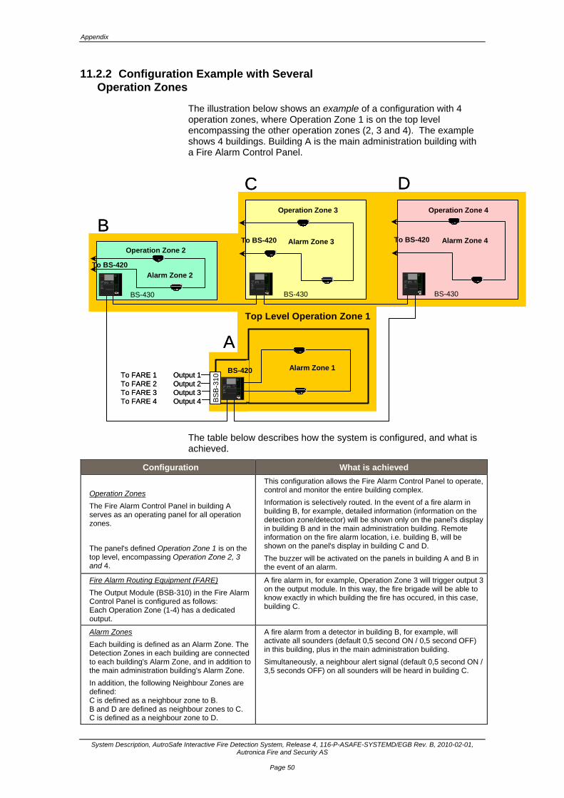
Appendix
System Description, AutroSafe Interactive Fire Detection System, Release 4, 116-P-ASAFE-SYSTEMD/EGB Rev. B, 2010-02-01, Autronica Fire and Security AS
Page 50
11.2.2 Configuration Example with Several Operation Zones
The illustration below shows an example of a configuration with 4 operation zones, where Operation Zone 1 is on the top level encompassing the other operation zones (2, 3 and 4). The example shows 4 buildings. Building A is the main administration building with a Fire Alarm Control Panel.
Operation Zone 2
Operation Zone 3 Operation Zone 4
Top Level Operation Zone 1
Alarm Zone 2
Alarm Zone 3 Alarm Zone 4
Alarm Zone 1
BS
B-3
10
BS-430
To FARE 1 Output 1To FARE 2 Output 2To FARE 3 Output 3To FARE 4 Output 4
BS-420
BS-430 BS-430
A
B
C D
To BS-420To BS-420
To BS-420
Power
Fire Brig. recvd.
Fire vent. activ.
Fire ext.. acktivated
0
A L A R M
?
C
987
654
321
Silence buzzer
Silence sounders
Reset
More Alarms
Prewarning
Early warning
System fault
Function disabled
Test
Fault
Self Verify
Power
Fire Brig. recvd.
Fire vent. activ.
Fire ext.. acktivated
0
A L A R M
?
C
987
654
321
Silence buzzer
Silence sounders
Reset
More Alarms
Prewarning
Early warning
System fault
Function disabled
Test
Fault
Self Verify
The table below describes how the system is configured, and what is achieved.
Configuration What is achieved
Operation Zones
The Fire Alarm Control Panel in building A serves as an operating panel for all operation zones.
The panel's defined Operation Zone 1 is on the top level, encompassing Operation Zone 2, 3 and 4.
This configuration allows the Fire Alarm Control Panel to operate, control and monitor the entire building complex.
Information is selectively routed. In the event of a fire alarm in building B, for example, detailed information (information on the detection zone/detector) will be shown only on the panel's display in building B and in the main administration building. Remote information on the fire alarm location, i.e. building B, will be shown on the panel's display in building C and D.
The buzzer will be activated on the panels in building A and B in the event of an alarm.
Fire Alarm Routing Equipment (FARE)
The Output Module (BSB-310) in the Fire Alarm Control Panel is configured as follows: Each Operation Zone (1-4) has a dedicated output.
A fire alarm in, for example, Operation Zone 3 will trigger output 3 on the output module. In this way, the fire brigade will be able to know exactly in which building the fire has occured, in this case, building C.
Alarm Zones
Each building is defined as an Alarm Zone. The Detection Zones in each building are connected to each building's Alarm Zone, and in addition to the main administration building's Alarm Zone.
In addition, the following Neighbour Zones are defined: C is defined as a neighbour zone to B. B and D are defined as neighbour zones to C. C is defined as a neighbour zone to D.
A fire alarm from a detector in building B, for example, will activate all sounders (default 0,5 second ON / 0,5 second OFF) in this building, plus in the main administration building.
Simultaneously, a neighbour alert signal (default 0,5 second ON / 3,5 seconds OFF) on all sounders will be heard in building C.
Power
Fire Brig. recvd.
Fire vent. activ.
Fire ext.. acktivated
0
A L A RM
?
C
987
654
321
Silence buzzer
Silence sounders
Reset
More Alarms
Prewarning
Early warning
System fault
Function disabled
Test
Fault
Self Verify
Power
Fire Brig. recvd.
Fire vent. activ.
Fire ext.. acktivated
0
A L A RM
?
C
987
654
321
Silence buzzer
Silence sounders
Reset
More Alarms
Prewarning
Early warning
System fault
Function disabled
Test
Fault
Self Verify

Appendix
System Description, AutroSafe Interactive Fire Detection System, Release 4, 116-P-ASAFE-SYSTEMD/EGB Rev. B, 2010-02-01, Autronica Fire and Security AS
Page 51

Reader’s Comments
System Description, AutroSafe Interactive Fire Detection System, Release 4, 116-P-ASAFE-SYSTEMD/EGB Rev. B, 2010-02-01, Autronica Fire and Security AS
12. Reader’s Comments Please help us to improve the quality of our documentation by returning your comments on this manual: Title: Installation Handbook, AutroSafe Interactive Fire Detection System, Release 4,
Ref. No.: 116-P-ASAFE-SYSTEMD/EGB Rev. B, 2010-02-01
Your information on any inaccuracies or omissions (with page reference):
Please turn the page

Reader’s Comments
System Description, AutroSafe Interactive Fire Detection System, Release 4, 116-P-ASAFE-SYSTEMD/EGB Rev. B, 2010-02-01, Autronica Fire and Security AS
Suggestions for improvements
Thank you! We will investigate your comments promptly.
Would you like a written reply? Yes No
Name: ------------------------------------------------------------------------------------------------
Title: ------------------------------------------------------------------------------------------------
Company: ------------------------------------------------------------------------------------------------
Address: ------------------------------------------------------------------------------------------------
------------------------------------------------------------------------------------------------
------------------------------------------------------------------------------------------------
Telephone: ------------------------------------------------------------------------------------------------
Fax: ------------------------------------------------------------------------------------------------
Date: ------------------------------------------------------------------------------------------------
Please send this form to: Autronica Fire and Security AS
N-7483 Trondheim
Norway
Tel: + 47 73 58 25 00
Fax: + 47 73 58 25 01
www.autronicafire.com

Reader’s Comments
System Description, AutroSafe Interactive Fire Detection System, Release 4, 116-P-ASAFE-SYSTEMD/EGB Rev. B, 2010-02-01, Autronica Fire and Security AS
Autronica Fire and Security is an international company, headquartered in Trondheim, one of the largest cities in Norway. The company is owned by United Technologies Corporation and employs more than 319 persons with experience in developing, manufacturing and marketing of fire safety equipment. Our products cover a broad range of systems for integrated solutions, including fire detection systems, integrated fire and gas detection systems, control and presentation systems, voice alarm systems, public address systems, emergency light systems, plus suppression systems. All products are easily adaptable to a wide variety of applications, among others, hospitals, airports, churches and schools, as well as to heavy industry and high-risk applications such as power plants, computer sites and offshore installations, world wide. The company's strategy and philosophy is plainly manifested in the business idea: Protecting life, environment and property.
Quality Assurance
Stringent control throughout Autronica Fire and Security assures the excellence of our products and services. Our products are CE marked and developed for worldwide standards and regulations, and conform to the CEN regulation EN54. Our quality system conforms to the Quality System Standard NS-EN ISO 9001:2000 and is valid for the following product and service ranges: marketing, sales, development, engineering, manufacture, installation, commissioning and servicing of suppression, integrated fire and gas detection and alarm systems, plus petrochemical, oil and gas instrumentation systems for monitoring and control.
Autronica Fire and Security AS Headquarters, Trondheim, Norway. Phone: + 47 73 58 25 00, fax: + 47 73 58 25 01. Head Office Oil & Gas, Stavanger, Norway. Phone: + 47 51 84 09 00, fax: + 47 51 84 09 99. Division Oil & Gas, Oslo, Norway. Phone: + 47 23 17 50 50, Fax: + 47 23 17 50 51 Division Oil & Gas, PO Box 416, Farnborough GU14 4AT, UK. Phone: + 47 51 84 09 00, Fax: + 44 84 52 80 20 55 Division Maritime, Suppression/New Build Detection & Alarm. Norway. Phone: + 47 31 29 55 00, Fax: + 47 31 29 55 01 Division Maritime, After Sales/Service Detection & Alarm, Norway. Phone: +47-73 58 25 00, Fax: +47-73 58 25 01
Visit Autronica Fire and Security's Web site: www.autronicafire.com