system description e1.2 - generic 1 - great dane...
TRANSCRIPT

GENERIC 1/45
ETELM
9, avenue des Deux Lacs
P.A de Villejust
91971 Courtaboeuf – cedex
Tel : +33.1.69.31.22.84
Fax : +33.1.69.31.22.61
Web site : www.etelm.fr
RC : Evry 320 565 443
EETTEELLMM SSYYSSTTEEMM DDEESSCCRRIIPPTTIIOONN
GGEENNEERRIICC

GENERIC 2/45
TABLE OF CONTENT
1. GENERAL OVERVIEW ............................................................................................................. 4
1.1 PURPOSE ......................................................................................................................... 5
1.2 GLOSSARY ....................................................................................................................... 6
2. NETWORK ARCHITECTURE ................................................................................................... 8
2.1 OVERVIEW .......................................................................................................................... 9
2.2 LINK ARCHITECTURE .......................................................................................................... 13
2.2.1 Link based up on E1 G703 ........................................................................................... 13
2.2.2 Link based on IP .......................................................................................................... 13
2.3 EXPANSION CAPABILITY ..................................................................................................... 15
3. SYSTEM FOR CUSTOMER .................................................................................................... 16
3.1 CUSTOMER SYSTEM OVERVIEW ...................................................................................... 17
3.2 SYSTEM RESOURCES & SUBSCRIBERS ............................................................................... 19
3.3 FUTURE EXPANSION .......................................................................................................... 20
4. TETRA RADIO EQUIPMENT .................................................................................................. 21
4.1 TETRA IP@NODE ............................................................................................................. 22
4.1.1 Overview ...................................................................................................................... 22
4.1.2 Base Station Interface .................................................................................................. 23
4.1.3 Network Management Console Interface ..................................................................... 24
4.1.4 Dispatching System Interface ....................................................................................... 24
4.1.5 PABX/ PSTN Interface ................................................................................................. 25
4.2 TBS25 TETRA BASE STATION ........................................................................................... 26
4.2.1 Overview ...................................................................................................................... 26
4.2.2 Tetra Features ............................................................................................................. 27
4.2.3 Equipment Modules ..................................................................................................... 27
4.2.4 Site Configurations ....................................................................................................... 27
4.2.5 System Parameters ..................................................................................................... 28
4.2.6 Fall back Mode ............................................................................................................ 28
4.2.7 Technical Specifications ............................................................................................... 29
4.3 OPEN SOURCE APPLICATIONS DEVELOPMENT ..................................................................... 31
4.4 TSC10 NETWORK MANAGEMENT TERMINAL ........................................................................ 31
4.4.1 Overview ...................................................................................................................... 31
4.5 DISPATCHER STATION ....................................................................................................... 33
4.6 AUTOMATIC VEHICLE LOCATION (AVL) – (OPTIONAL) ........................................................... 35
4.7 IP RECORDER SERVER (OPTIONAL) .................................................................................... 36
4.8 AUDIO MAILBOX GATEWAY (OPTIONAL) ............................................................................... 37
5. ENGINEERING SERVICES & SUPPORT ............................................................................... 38
5.1 ETELM APPROACH ........................................................................................................... 39
5.2 TETRA THEORY TRAINING .................................................................................................. 39
5.3 NMS TRAINING ................................................................................................................. 40
5.4 MAINTENANCE TRAINING .................................................................................................... 41
5.5 TERMINALS TRAINING ........................................................................................................ 42
5.5.1 Terminal configuration.................................................................................................. 42
5.5.2 Terminal use ................................................................................................................ 42
6. CONCLUSIONS ...................................................................................................................... 43

GENERIC 3/45
TABLE OF FIGURES
Figure 2-1 : Multi IP@node TETRA radio network configuration ........................................................ 9
Figure 2-2 : Sub network IP meshed architecture ............................................................................ 10
Figure 2-3 : Sub network using star architecture ............................................................................. 10
Figure 2-4 : Redundancy – Failure scenarios at sub network level .................................................. 11
Figure 2-5 : Multi IP@node with dynamic RBS attachment ............................................................. 12
Figure 2-6 : Multi IP@node configuration – independent networks .................................................. 13
Figure 2-7 : Ring & Star architecture ............................................................................................... 13
Figure 2-8 : Typical communication scheme for TETRA .................................................................. 14
Figure 3-1 : Customer Tetra System Overview ................................................................................ 18
Figure 4-1 : ETELM IP@node ......................................................................................................... 22
Figure 4-2 : TETRA Base Station .................................................................................................... 26
Figure 4-3: Network Management Terminal .................................................................................... 31
Figure 4-4: Dispatcher WorkStation ................................................................................................. 33
Figure 4-5: AVL WorkStation ........................................................................................................... 35
Figure 4-6: IP Recorder server ........................................................................................................ 36
Figure 4-7 : Audio Mail Box Gateway .............................................................................................. 37

GENERIC 4/45
1. GENERAL OVERVIEW

GENERIC 5/45
1.1 PURPOSE
The aim of this document is to describe the main system features proposed by the ETELM Digital Trunking Radio Network manufactured by ETELM in compliance with the TETRA standard defined by the ETSI organisation.
1.1.1.1 ETELM Overview
ETELM is also a member of the TETRAMoU organisation in charge of assuring the Interoperability between TETRA infrastructure equipment and terminals proposed by several different manufacturers. ETELM is a French company which has existed in the radio market for over 28 years, we are well known on the TETRA market for our capability and flexibility to supply digital radio network systems. ETELM is an independent company concentrating on the development and manufacture of core tetra Network infrastructure, we are completely vendor neutral for Tetra terminals and fully support Inter-operability of Tetra terminals on our networks. ETELM has the capability to propose the most efficient technology according to the customer requirements. Many of the TETRA radio networks supplied by ETELM use different terminal manufacturers for those customers, it is essential to mix terminal manufacturers according to the huge quantity of terminals used on the same radio network and diversity of user demands, even in extremely difficult environments. Etelm has supplied a wide variety of Tetra Networks, from the single site configuration to the multi site configuration, ETELM manufactures several infrastructure products which are fully compatible. The compatibility assures to implement a TETRA radio network from a single site configuration to a multisite configuration by addition of components, and the re-use of all existing hardware.
ETELM infrastructure ensures also interoperability of terminal operating simultaneously on the same network with main tetra terminal manufacturers – we have followed the formal IOP test Procedure as specified by Tetra MoU. ETELM supplies it’s products through accredited Systems Integration Partners worldwide and has a full programme of training and support for our local suppliers and end users. A comprehensive reference list document and case studies are provided separately.

GENERIC 6/45
1.2 GLOSSARY
Description AI Air Interface
AIE Air interface encryption AKD Authentication and Key Distribution system
AKMT Authentication Key Management Tool API Application Programming Interface
ASCCH Assigned Secondary Control Channel AVL Automatic Vehicle Location
CA Certification Authority
CB Combiner C2 Command and Control
CDR Call Data Record CLIP Calling Line Identification Presentation
CLIR Calling Line Identification Restriction
DGNA Dynamic Group Number Assignment DHCP Dynamic Host Configuration Protocol DMO Direct Mode Operation
DMR Digital microwave radio unit DNS Domain Name System E2EE End-To-End Encryption
EMI Electromagnetic Interference ETSI European Telecommunications Standards Institute
FSSN Fleet Specific Short Number
FTP File Transfer Protocol
GPRS General Packet Radio Service GPS Global Positioning System GSM Global System for Mobile Communications
GTSI Group TETRA Subscriber Identity GUI Graphical User Interface
IP Internet Protocol IPSec Internet Security Protocols
ISDN Integrated Services Digital Network ISI Inter System Interface
ISP Internet Service Provider IT Information Technology
ITSI Individual TETRA Subscriber Identity
ITU-T G.703/G.704-compliant line) K Radio terminal authentication key
LAN Local Area Network LAPD Link access procedure on the D-channel LLC Logical link control
LNA Low-noise amplifier MCCH Main Control Channel MGT Management
MMI Man Machine Interface MS Mobile Station NMT Network Management Terminal

GENERIC 7/45
NMEA National Marine Electronics Association OSI Open Systems Interconnect PABX Private Automatic Branch Exchange PC Personal Computer
PCI Peripheral Component Interface
PDCH Packet Data Channel PDCU Packet Data Communications Unit PDP Packet Data Protocol
PDU Packet Data Unit PIN Personal Identity Number PMR Professional Mobile Radio
PSTN Public Switched Telephone Network
PTT Push-to-talk QoS Quality of Service RAM Random Access Memory
RF Radio Frequency RTC Real-Time Clock
RX Receiver SDS Status and short data message SDS-TL SDS Transport Layer SwMI Switching and Management Infrastructure
TRBS TETRA Radio Base Station
TCH Traffic Channel TCP/IP Transmission Control Protocol/Internet Protocol
TDMA Time-division Multiple Access TETRA TErestrial Trunked RAdio
TX Transmitter
VLAN Virtual LAN VLR Visitor Location Register
VPN Virtual Private Network WAN Wide Area Network WAP Wireless Access Protocol

GENERIC 8/45
2. NETWORK ARCHITECTURE

GENERIC 9/45
2.1 Overview
The network architecture of the TETRA radio network proposed by ETELM is based upon multi-IP@node configurations interconnected to a Wide Area Network using IP standard protocols.
The multi IP@node configuration provides the most efficient architecture in terms of performances, robustness against multiple failures on the transmission network, easy integration within an existing IT networks and capability to interface external software applications to the radio network, quality of service and availability of the radio network required for professional mobile radio users.
IP@node manages a radio sub network as if it is an independent radio network with the capability to be interconnected to another IP@node for permitting inter-networks communications. Each sub networks can be configured to operate as a local radio network and all traffic are managed through the local IP@node.
This architecture optimises the dataflow required for local communication area and improves inter-networking communications between IP@nodes.
This configuration also authorises the usage of several radio sub networks dedicated to specific organisation and upon demand organisation can share a part or their overall network.
Figure 2-1 : Multi IP@node TETRA radio network configuration

GENERIC 10/45
Figure 2-2 : Sub network IP meshed architecture
The sub-network configuration can be composed of direct IP Ethernet connection from the base station or from the IP@node so as to integrate a TETRA radio network within an existing IP backbone. In that case, each component requires an access to the IP network in order to communicate with other infrastructure equipment.
Operator’s consoles like dispatcher, NMT or AVL can operate directly through the existing Local Area Network and communicate with Ip@nodes (dual redundancy capability) and PABX/PSTN gateways connected to telephone lines. The main interface with external IP backbone is based upon a router device.
Furthermore, the ETELM infrastructure is also able to support standard star architecture configuration using E1 links, V11 or V35 wherever existing transmission networks using multiplexers / demultiplexer devices will be used for integration of the TETRA radio network..
Figure 2-3 : Sub network using star architecture

GENERIC 11/45
The resilience of the radio network is dependent upon the sub network architecture (star, ring or meshed) and also upon the capability of the system to provide the service after multiple random failures occurring at different level of the network.
The diagram attached below describes the different levels of failures.
Green links shows parts of the system in operation
Red links shows parts of the system not in operation
Figure 2-4 : Redundancy – Failure scenarios at sub network level
The network architecture is fully transparent for terminal users. Terminal users can be authorised, by the network administrator, to migrate to another sub network or several others sub networks.
A full redundancy of the equipment can be proposed to secure sub networks with mechanisms of dynamic attachment for radio base stations to other sub networks in case of disconnection with the preferred IP@node equipment.

GENERIC 12/45
Figure 2-5 : Multi IP@node with dynamic RBS attachment
This architecture offers following advantages:
Geographic security: in case of a disaster in an area, others area are not affected: there are no common central equipments (SW, data base,...) for the whole network – that is there are no sensitive location where a destruction may affect the whole network.
Functional security: each sub network can be equipped with a full duplicated IP@node.
P@node duplication is independent from one sub network to the other.
Extension capacity: the capacity of each sub network is larger than required and each sub network may be easily extended. In another hand, one may add others sub networks.
Link
failure
Radio
site
Radio
site
Radio
site
Radio
site
Radio
site
Radio
site
IP
network IP network
SW / NMS SW / NMS
link
Radio
site
Radio
site
Radio
site
Radio
site
Radio
site
Radio
site
IP
network IP network
IP@node /
NMS
IP@node /
NMS

Figure 2-6 : Multi
Each sub network can be completely independent from the other one and reliability is assured thanks to the stand alone mode with full features provided
2.2 Link Architecture
2.2.1 Link based
Several types of link architecture can be supported by the TETRA network like or ring architecture which is mainly based upon transmission network equipment (microwaves)
The ETELM solution is perfectly adapted to be interfthe data bandwidth required for each radio sitethrough the E1 protocol. G703 2Mbit/s interfaces support theto fit with the exact number of slots required for each radio site As example, a G703 link is configured to operate with a single slot from the 30 slots available on a 2 Mbit/s links. The band width required is only 64 Kbit/s per base station (frequency carrier).
2.2.2 Link based on IP
Depending on the transmission networkused, the links of the TETRA system proposed by ETELM can support direct LAN connections through the IP protocols. In that case, mainly two protocols are used:
TCP/IP for signalling transmissions UDP for audio transmission
TETRA radio communication networks design is not similar to the well known GSM networks.
GENERIC
Multi IP@node configuration – independent networks
completely independent from the other one and reliability is assured thanks to the stand alone mode with full features provided for each sub networks
Link Architecture
Link based up on E1 G703
of link architecture can be supported by the TETRA network like mainly based upon E1 G703, V11 or V35 links available
equipment (microwaves).
Figure 2-7 : Ring & Star architecture
perfectly adapted to be interfaced to those types of networks data bandwidth required for each radio site and providing the synchronisation
interfaces support the implementation of the internal drop and insert multiplex service number of slots required for each radio site connected to IP@node
As example, a G703 link is configured to operate with a single slot from the 30 slots available on a 2 Mbit/s links. The band width required is only 64 Kbit/s per base station (frequency carrier).
Link based on IP
Depending on the transmission network architecture or existing telecommunication networks to be used, the links of the TETRA system proposed by ETELM can support direct LAN connections
In that case, mainly two protocols are used:
transmissions UDP for audio transmission
TETRA radio communication networks design is not similar to the well known GSM networks.
13/45
independent networks
completely independent from the other one and reliability is assured for each sub networks.
of link architecture can be supported by the TETRA network like the star architecture E1 G703, V11 or V35 links available from the
aced to those types of networks by optimising synchronisation service directly
internal drop and insert multiplex service connected to IP@node equipment.
As example, a G703 link is configured to operate with a single slot from the 30 slots available on a 2 Mbit/s links. The band width required is only 64 Kbit/s per base station (frequency carrier).
architecture or existing telecommunication networks to be used, the links of the TETRA system proposed by ETELM can support direct LAN connections
TETRA radio communication networks design is not similar to the well known GSM networks.

GENERIC 14/45
Indeed, a TETRA network must handle a lot of multipoint communications, while GSM communication scheme is only point to point. Typically, in a Professional Mobile Radio communications (PMR) most part of the communication are group calls in comparison with individual calls mainly used when interconnection with an external system shall be realised like PSTN access. Furthermore, even in case of individual calls, any communication must be monitored by third parties like dispatcher consoles and/or recorded by a specific equipment device. Typical communications involve simultaneously several radio sites, several dispatchers and at least a recorder. The main objective on a TETRA network is to establish communications as fast as possible and to optimise the audio path by reducing the number of radio resources involve within the call.
Figure 2-8 : Typical communication scheme for TETRA
If the audio is carried by point to point messages, the IP traffic drastically increases and data bandwidth required at the IP backbone level also increase. In order to prevent it, the data packets including audio are broadcasted inside a sub network. Each component of the TETRA system having been previously authenticated may listen to a communication by selecting the right communication number. Any other components which are not authorised by the system and are connected to this sub network can not get access to the audio message. Communication numbers are managed by the system and all on going communication signalling is also broadcasted. Such broadcasted method is very efficient; it uses UDP messages with restricted domain. The implementation of TETRA IP Router within the IP backbone ensure the full broadcast management of the audio and permit optimisation of data bandwidth required at node levels.
Dispatcher 2 Monitoring the communication
Dispatcher 1 Monitoring the communication
Communication recorder
Radio site 1
Radio site 2
Group of hand
portables
Network

GENERIC 15/45
2.3 Expansion Capability
Each sub-network may be easily extended to increase traffic capacity and also the radio coverage. By addition of TETRA radio base station to the sub network, the global communication network can be expanded. Base stations may be added anywhere on the LAN or WAN and also base station equipment may be added on a radio site, without any change to existing equipments. Each sub-network may handle up to 128 TETRA carriers.

GENERIC 16/45
3. SYSTEM FOR CUSTOMER
GENERIC 17/45
3.1 CUSTOMER System Overview
The Etelm system is provided based on the scope and requirements as discussed with Customer. The System comprises an Etelm Central Switch co-located with a 2 Carrier (Tetra Basestations) Site along with Network Management System which allows full administration and back-up of system.
In addition to the core Tetra hardware on this site Etelm has provided a Telephone interface, the type of telephone connection is to be confirmed however two options are available either 2 lines [Basic Rate Interface (BRI)], or full PABX interface providing up to 30 lines over QSIG or EU-ISDN connection to PABX [Primary Rate Interface (PRI)].
3 Additional BTS Sites are provided one with 2 Carriers (1 Control & 7 Traffic Channels) and the other two with 1 Carrier (1 Control & 3 Traffic Channels).
As the system will be interlinked to other sites over Ethernet IP, then each BTS Site will require a GPS Antenna connected to the built-in GPS receiver in the Etelm BTS. This GPS facility provides synchronisation between sites and allows cell handover during calls without interruption. GPS Antennas/Splitters are not included as cable heights are yet to be confirmed.
At each Basesite the system is designed with Duplexer for 1 Single Tx/Rx Antenna operation, no diversity reception, RF Antenna & Cabling is not included subject to confirmation of antenna heights.
The Etelm system supports multiple receiver diversity as an option; this is a feature of Tetra to improve the uplink performance and thereby the RF coverage. Most systems offer up to 3 way diversity where-as the Etelm system offers up to 6 Way diversity. As no diversity was requested the standard Etelm chassis supporting up to 2 way diversity was proposed, this would require only an additional receiver card for 2 Way diversity plus Additional Rx Antenna. If 3 to 6 way diversity is required in the future, then a chassis upgrade would be required to TBS25-D in addition to the additional Receiver cards (all other cards could be retained). Alternatively the proposal could be amended to allow TBS25-D chassis in Phase 1 which would then allow for up to 6 Receiver boards to be included in future.
At this stage no coverage assessment has been performed so it is not yet clear if diversity is actually required.
Two Fixed Mobiles are provided for Direct Mode Gateway operation.
Each Etelm TBS25 carrier/basestation has 8 inputs for external alarms and 7 outputs for triggering events or actions locally, these allow interaction and alarms from the local site to be transmitted over the air as messages or alarms to subscribers. This is useful for site security and system maintenance.
The Etelm solution is fully redundant – every carrier/basestation has it’s own control built-in, so there is no single point of failure. In the event of loss of inter-site links then each site retains it’s own user database allowing registered subscribers to make calls between other users on it’s local BTS cell site. If the link fails each site will become autonomous Tetra cell sites – the 2 carrier site will still operate as an independent site with 1 control channel and 7 traffic channels. Obviously no inter-site individual or group calls/messages will be made until the link is restored.
In fallback mode the user can select any talkgroup on their portable/mobile and call any group, only users registered on the local site will receive the group call. If a subscriber is off when the system goes into fallback mode (loses link) then it will automatically register with the site when switched on provided it is a member of the site database.
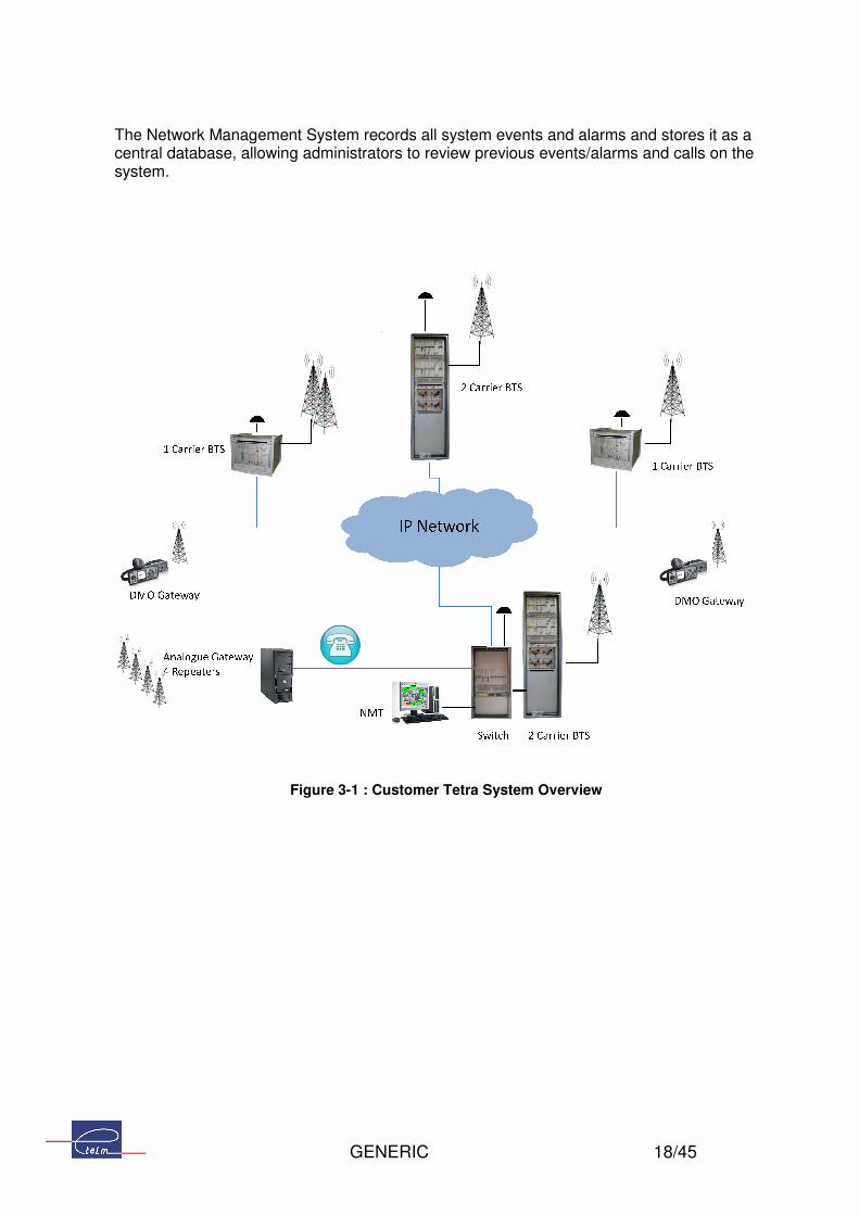
The Network Management System records all system events central database, allowing administrators to review previous events/alarms and calls on the system.
Figure
GENERIC
The Network Management System records all system events and alarms and stores it as a central database, allowing administrators to review previous events/alarms and calls on the
Figure 3-1 : Customer Tetra System Overview
18/45
and alarms and stores it as a central database, allowing administrators to review previous events/alarms and calls on the
GENERIC 19/45
3.2 System Resources & Subscribers
The Etelm system is designed in accordance with the ETSI Tetra standard specifications. This standard is designed to accommodate up to 10 Million subscribers on a single system. Clearly there is a practical limitation for any system based on the available resources and users making calls. Although the system caters for a large number of subscribers the factors determining the system resources required to cater for the number of subscribers is based on a grade of service calculation. In order to calculate the grade of service provided based on the design, it is necessary to understand the system usage, based on:
� No. Calls made per hour � Duration of Calls � Call Types – Individual or Group � No. Subscribers on each Site � Inter Site Calls � Radio to Radio calls � Radio to Telephone (usually full duplex calls).
With this information Etelm can assist in calculating the grade of service as necessary. Etelm’s system is fully inter-operable with all available Tetra Subscriber equipments. This gives the user the ability to select the subscriber equipment preferred or ones that offer any specific functionality required. The Etelm system supports several hundred Talk Groups, in addition to Dynamic Grouping or Re-Grouping.

GENERIC 20/45
3.3 Future Expansion
The Etelm system is designed to allow future expansion, the Etlm IP Switch supports up to 256 Tetra Carriers (Tetra Basestations), so it is possible to add additional BTS sites connected back to the existing Switch by providing additional IP connections to the Switch. You may add many Switches over IP no physical or software limit has been imposed but the maximum number of switches would be determined would be determined by the links bandwidth. For Microwave Links the Switch and Basestation needs a COM card, this will reduce the capacity of the Switch – if all Microwave then standard capacity is 11 Sites (max 4 Carriers per site) over E1 per switch, there is an expansion rack for the switch to accommodate up to 25 Sites (additional 14 Sites). Where the system expands on a National scale it is usual to add additional Switches on a regional basis to provide local management and control. Future expansion possibilities may be discussed at any time.

GENERIC 21/45
4. TETRA RADIO EQUIPMENT

GENERIC 22/45
4.1 TETRA IP@node
4.1.1 Overview
Figure 4-1 : ETELM IP@node
The TETRA IP@node is a full IP product being capability to interface many types of equipment for the TETRA infrastructure and also any external networks. The IP@node allows a flexible and a resilient architecture specially designed to fit with the customer constraints applying to a professional mobile radio network.
Using an IP node philosophy for radio sites and a direct IP Ethernet connection from the base station to the IP@node, the digital TETRA radio network proposed by ETELM is the most convenient for assuring communications in any situations. Those nodes can be interconnected to any type of network like star architecture, rings or meshed IP networks.
The multi IP@node facility ensure highest performances for communications, robustness against failures and adaptability to customer existing networks.
The multi IP@node architecture ensures reliability of the radio network because there is no single point of failure. Upon failure detection of an IP@node, base stations are automatically reconnected to the most appropriate neighbour IP@node equipment. Each IP@node can ensure redundancy for the neighbour equipment.
The TETRA IP@node is responsible for all the Level 3 and higher tasks of the ETSI TETRA standard which includes communications management and mobility management. The operation of an IP@node can be monitored via the Network Administration Console, and it can be accessible to external application by the dispatching network via TCP/IP.

GENERIC 23/45
The IP@node is a modular chassis which can be easily integrated within a standard 19 inches cabinet and composed of dedicated boards for each interfaces. Any expansion requirements are easily fulfilled by addition of another chassis.This component of the network contains a part of the intelligence of the system which is also shared with CPU units integrated within each base station at the radio site level.
The equipment is designed to support normal vibrations, bumps and knocks incurring during transportation. The equipment does not cause any electrostatic discharges to he environment.
4.1.2 Base Station Interface
Several types of Base station interfaces are available like IP Ethernet 100Mbit/s port or G703, V11 or V35 depending on field configuration, bandwidth and transmission network.
Ethernet port interfaces can be plugged directly to Ethernet Switch equipment or any Commercial on the Shelf (COTS) router devices. The data bandwidth offered is 10 or 100 Mbit/s.
Other Interface are either G703 or V11 or V35 In case of using standard 2Mb/s G703 access, a base station uses one standard time slot of the link. Internal drop and insert multiplex integrated in any base station offers the possibility to connect radio sites in a daisy chain way on the same 2Mb/s link. (the physical architecture is a daisy chain but the functional architecture remains a star one).
As soon as a base station is connected to its own IP@node, configuration parameters are automatically transmitted including carrier frequencies, power settings and access mode.
Base stations needs to be accurately synchronised, mainly for mobile roaming performances. This synchronisation is achieved (low and high level) either through the G703 2Mb/s links, without additional equipments, or with GPS, by adding external antenna at each radio site location.
Audio Signalling& Data Transmission
Data to be broadcasted to all subscriber radios within local site covered by each base station Subscriber radio’s registration and assignment data Audio signalling data Audio blocks Control Signalling data SDS messages Bearer data packets
Operating Modes
The IP@node manages the operating mode for each base station with – Assignment of channels (MCCH, SCCH, etc.), power modes and others

GENERIC 24/45
4.1.3 Network Management Console Interface
A local or remote Network Management Console can be connected to the IP@node through a direct IP Ethernet port.
The network management interface manages features as detailed below:
Technical Database
Manage the configuration files of all base stations of the network Manage the configuration files of subsets constituting the IP@node Routing table for flows between various network equipment Maintain the operating parameters of the network
Administrative Database
Visiting mobile acceptance criteria Declaration of resident mobiles
System Monitoring
Allows permanent control of the network by sending all summary information pertinent to the states and statuses of various network equipment and communication links to the Administration Console.
Event Logging
Alarms and acknowledgement Registration and De-registration of mobiles Call requests from subscriber radios Call setup and call release User group assignments
4.1.4 Dispatching System Interface
A local or remote dispatcher console can be connected to the IP@node through a direct IP Ethernet port.
Furthermore, the Dispatcher system interface is also able to interconnect Computer-based Dispatching System through IP Ethernets ports.
The dispatcher interface manages features as detailed below:
Signalling
1 UDP channel for the broadcasting of network communications and data transmission such as SDS and Status messages
1 TCP/CP channel

GENERIC 25/45
Audio
1 UDP channel for voice
4.1.5 PABX/ PSTN Interface
The IP@node equipment is able to support dedicated interface in order to interconnect the TETRA radio Network to a private PABX or to the Public Network (PSTN). Several type of interfaces are available like S0/T0 interfaces permitting to establish one simultaneous communication between the TETRA network and telephone through the PABX. Another card is a T2 interface permitting up to 30 simultaneous communications between the radio network and the telephony world. The same type of interface can also be plugged at the radio site level to interface local PABX, if required.

GENERIC 26/45
4.2 TBS25 Tetra Base Station
4.2.1 Overview
Figure 4-2 : TETRA Base Station
ETELM TBS25 combines high transmit power of 25W with High receiver Sensitivity -118dBm - for all Tetra systems the critical factor determining coverage is the Uplink transmit power (portables/mobiles to basestation site) and so the most important factor for the basestation is not Tx power but receiver sensitivity – Etelm has one of the highest class of receiver sensitivity for it’s TBS25. Additionally Etelm may offer up to 6 Ways of Receiver Diversity – where the industry standard is 3 ways. This again offers the user a method to increase the coverage by maximising the uplink reception. The TBS25 manages a single carrier of a TETRA site. It is responsible for the routing of the following traffic via the IP@node:
“Writing In” of the Mobile Stations (according to a programmed table) Selective mobile/mobile or mobile/base call (half or full-duplex) Group call from a mobile or from a base “Open Channel” call Mobile / Telephone interconnect call Mobile / Dispatching Network communications in both directions SDS - Mobile / Dispatching Network, Dispatching Network / Mobile, Mobile / Mobile SDS to user groups Broadcast of network information User Data transmission by IP packet
The equipment is designed to support normal vibrations, bumps and knocks ocurring during transportation. The equipment does not cause any electrostatic discharges to he environment.

GENERIC 27/45
4.2.2 Tetra Features
TBS25 integrates and complies to all level 1 and 2 functionalities provided for in the ETSI TETRA V+D standard.
Level 1 includes compliance transmission and reception on 25 kHz channels, modulation/demodulation, coding and error correction.
Level 2 includes MAC and LCC (basic and advanced links)
All these features allow the using of the base station to route 4 voice and/or data calls in circuit mode, protected circuit mode or packet mode. Each base station is controlled by the IP@node to “carry” the MCCH and SCCH channels. It is assumed that at least one base station from a radio site manage to broadcast signalling information through the air interface using the first slot for signalling purpose. As a basic feature supported within each base station, a set of 8 external alarms (inputs per carrier) and 7 remote control (outputs per carrier) can be programmed in order to transmit those alarms to the network management terminal. Telemetry actions can be proposed easily from any network management terminals connected to the TEP radio network. Those Inputs/Outputs support direct dry contacts.
4.2.3 Equipment Modules
TBS11 base station can be directly interconnected through IP Ethernet Ports to a standard IP backbone so as to be interconnected to its preferred IP@node. TBS11 base station can also accommodate to interconnect through a G703 interface with a second communication board allowing a “daisy chain” multiplexing on the 2Mbps channel. TBS11 base station can accommodate up to 2 additional demodulators for receiver diversity operation, i.e. a total of 3 reception channels.
4.2.4 Site Configurations
4.2.4.1 Single Base Station
ETELM TBS25 Basestation supports up to 6 Ways of Diversity, Several configurations are available for site installation of a single frequency carrier depending on field requirements (radio coverage expected, site constraints,…).
With Diversity – 1 omni directional RX/TX with u pto 5 auxiliary RX antennas (Yagi – panels – omni)
Without Diversity – 2 antennas (1 for Tx and 1 for Rx respectively),
Without Diversity - 1 antenna using duplexer equipment

GENERIC 28/45
With Diversity – Up to 6 directional Rx antennas with 1 omni-directional Tx antenna,
Alternatively, Up to 6 duplexed directional antennas
Special combining systems can be designed to cover indoor areas like underground or
overhead coverage, for example, by RF distribution network or by Fibre Optical links.
4.2.4.2 Multi Base Station
Radio sites can be configured to support up to 8 base stations per site. Each base station is fully independent and can manage the air interface. Several RF configurations are available as described below:
Same as above RX combiner by pre-amp distribution (4 channels: 3 diversity channels) Hybrid or cavity combiner, Special combining system for underground and overhead coverage, for example, by RF
distribution network or by Fibre Optical links.
4.2.5 System Parameters
The TBS11 parameters are provided entirely from the IP@node except for the link configuration. As soon as the base station is connected to a IP@node, the latter will automatically send its configuration file. A file reload can also be initiated upon TBS11 requests or when the IP@node detects a fault with a base station. If the IP@node is re-initialized or the configuration file undergoes a general reload, the configuration files of all base stations of the network are systematically retransmitted.
4.2.6 Fall back Mode
When a TETRA radio site is disconnected from the IP@node (ie: link failure), each base station of the affected site will operate in fall back mode. Then base stations transmit to all users under its coverage a broadcast message informing the fall back operation mode. According to the TETRA standard, terminals shall request registration to a neighbour radio site assuring radio coverage in this area, on which intersite calls services are still available. If there is no overlap coverage between radio sites, then terminals still operate through the same radio site, even if the site is isolated. The System is also able to be configured in order to remove the capability for the radio site to operate when the radio site is isolated. A base station in fall back mode is able to manage local traffic (mobile to mobile) according to the latest list of authorised mobiles known and recorded into the base station before the link failure.

GENERIC 29/45
All types of calls like individual calls (half duplex, full duplex), group calls and SDS services are available limited to local traffic. An authorisation list is pertinent to each TBS11 of the network and may be different from the network’s list of general authorizations. This feature also can be configured to restrict access to the TBS11 to a fleet of terminals getting higher priority than some other user. The encryption Class 2 mechanisms are still in operation using authentication process for each registration. The air interface is still encrypted using latest encrypted keys uploaded by the system. The TBS11 can be interfaced to the radio network by using direct IP connection. This configuration allows implementing standard IP protocols like OSPF to dynamically reroute and recover the link to the preferred IP@node or to any other neighbour IP@node connected to the IP backbone.
4.2.7 Technical Specifications
1 frequency carrier (TX frequency and RX frequency) support up to 4 TETRA channels
4.2.7.1 Frequency Band
The TETRA Base Station proposed by ETELM is available in the most common frequency band used. Those bands are detailed below:
380 – 400 MHz, 410 – 430 MHz, 450 – 470 MHz 806 – 870 MHz
The Duplex spacing, as standard is 10MHz for frequency range 380 – 470 MHz and 14 MHz for 806-870 MHz. On specific demand the duplex spacing can be configured. The frequency offset is also configurable (6,25kHz step)
4.2.7.2 Output Power
10 or 25 Watts available Integrated circulator for safety
4.2.7.3 Receiver
Diversity ( 1 to 3 receivers diversity) Static sensitivity: < -118 dBm excluding diversity gain TETRA Class A with multipropagation equaliser
4.2.7.4 Connectivity

GENERIC 30/45
Ethernet RJ45 100Mbit/s 64kbps link V.24, V.11, G703 (one time slot used only) at TETRA TLX-SAP 2Mbps multiplex integrated
4.2.7.5 Configuration
TETRA base station configuration is made automatically by remote downloading from the IP@node through the Management Console.
4.2.7.6 Operation & Maintenance
The maintenance procedures are operated directly from PC computer connected to the IP@node or at any point of the IP network.
Access to base station parameter Link and radio technical monitoring
4.2.7.7 Mechanical
19” rack mount 6U Dimension (Length x Heigth x Depth) : 600 x 300 x 600 mm
4.2.7.8 Main Power Supply
220V AC or 48V DC
4.2.7.9 GPS synchronisation
TETRA radio site must be synchronised for perfect hand over operation (all other features may be performed without such synchronisation). This synchronisation is either provided by the E1 G703 links from the IP@node equipment or by proposing GPS receiver located at each radio site posi As IP links can’t carry synchronisation signal with the required accuracy (about 10 microseconds), on use GPS synchronisation: A small standard GPS antenna is installed and the received signal is split to any carrier equipment. In case of long GPS antenna cables (more than 30 meters), it is always possible to insert small amplifier which are directly powered through the cable from the GPS receiver or splitter. GPS cable could be difficult to install for indoor base station.

GENERIC 31/45
4.3 Open Source Applications Development
ETELM has developed applications to cover the majority of standard needs – these are available to new customers on a network license basis, whereby should the client require multiple applications (say Dispatcher or AVL) to operate on the same network the user has permission to copy the software onto separate computers and configure and use as required. In addition, the Etelm system supports and open source interface which allows our Integration partners and customers to engineer their own unique applications – this requires a maximum of 10 days training for a software/application engineer.
4.4 Tsc10 Network Management Terminal
Figure 4-3: Network Management Terminal
4.4.1 Overview
The TSC10 Network Management terminal is based on a standard PC computer running through the operating system Microsoft Windows XP or Microsoft Vista edition. The Management console is connected to the TETRA Radio Network through an Ethernet IP connection. The Network Management terminal allows the complete control and monitoring of the TETRA network including IP@nodes, TBS11 base stations, PABX interfaces, dispatcher network and all gateways available for being connected to the TETRA world. In a node architecture network using multi-IP@node equipments, at least one network management terminal shall manage each IP@node. Network administration tasks include:

GENERIC 32/45
Technical monitoring & supervision of the network (e.g. alarms, busy status etc.) and present
graphically in a mimic diagram (depends on specific project requirements) Technical parameter settings of the network Administrative parameters settings include management of subscriber records and their
rights Record and retrieval of network events
The equipment is designed to support normal vibrations, bumps and knocks incurring during transportation. The equipment does not cause any electrostatic discharges to he environment.

GENERIC 33/45
4.5 Dispatcher Station
Figure 4-4: Dispatcher WorkStation
Dispatcher stations are made from a standard multimedia PC with 2 loudspeakers and microphone. Dispatch stations are connected to the IP@node through the LAN which carries Voice over IP. The 2 loudspeakers organisation (primarily used for stereo in standard use) allows offering functions for specific purpose as public safety:
one way (right loudspeaker) is used as a normal one for selective or group communication; the second (left loudspeaker) is used for discrete
listening of selected groups or mobiles. Main functions available from dispatch stations are:
selective call transmission to mobile (dialed or selected from an agenda) selective call to another dispatch station group call transmission (dialed or selected from an agenda) selective call receives from a mobile or another dispatch station (call to a dispatch station) with calling party identification – when the dispatch station is affected to this group group call receive from a mobile or another dispatch station (call to a dispatching) with
calling party identification send predefined status to mobile or group send SDS (typed or predefined) to mobile or group receive and display status and SDS with sending party identification display on going communication on the network discrete listening of a communication selected from the ongoing communication list selection of the mobiles and or groups to be listened on the second loudspeaker

GENERIC 34/45
short term recorder: this function allow the operator to listen back, as many time as wanted, the 4 last minutes of communications broadcasted from its loudspeaker – this is achieved in an ergonomic way with a programmable bargraph.
Interrogate the data base for a mobile or a group – edit and change information Set up and delete dynamic groups from selected mobiles
Several different ergonomics software are available for dispatch:
ergonomic standard dispatch ergonomic software applications dedicated to transport ergonomic features optimised for repetitive calls, with touch screen ergonomic operation for simultaneous multiple communications ....

GENERIC 35/45
4.6 Automatic Vehicle Location (AVL) – (optional)
Figure 4-5: AVL WorkStation
AVL workstations are designed from a standard multimedia PC with Large Flat screen and graphical capabilities to support any types of digital maps like satellite images, city maps. AVL workstations are connected to the IP@node through the LAN which transmit the GPS positions and Identities of terminal managed by the authorised user of the console. Main features available for AVL workstations are as follows:
Security and protection for accessing to the application (Login & password)
Remote control of mobiles for the configuration of the polling periodicity
display the location on a map (map license not included)
Display of terminal status by changing icons colours on the map (Switched off, normal, emergency)
Immediate localisation request from AVL user decision for a dedicated terminal
Administration and configuration of maps
Zoom in and out, list of terminal fleet to be displayed
The AVL workstation is able to support multi language capability. The AVL workstation is supplied with the dispatcher capability for ease of operation. Allows call set up directly from the map (Individual call, group call, conference call,…)

GENERIC 36/45
4.7 IP Recorder Server (optional)
Figure 4-6: IP Recorder server
The IP recorder device is based upon standard COTS equipment designed to provide the best performances in accordance with the minimum customer requirements. The recorder is fully compatible with latest IP technologies and can be interconnected in any area where the TETRA IP radio network can be accessed. All communications can be recorded on the IP recorder including the signalling information relating to the call like identity of the calling party, called party and speaker identity. The IP recorder includes RAID 5 controllers for hard Disks management and redundant hot swap power supply in order to secure audio information and to recover data upon potential hard disk failures. The main features supported by the IP recorder are as follows:
TETRA ACELP audio packet recorded through an IP standard format,
Large capacity for archiving TETRA records on Hard Disks,
Capacity to archive tetra records on DVD-ROM support,
Capability to replay tetra records on real time basis,
An automatic clean up service to prevent failures caused by full hard disks,
A SNMP management from the network management terminal. The Recorder Replay software can be installed within any consoles connected to the IP radio network and provides all services to select and listen to the corresponding communication. Rapid selection can be made by terminal identity, radio site location or date & time period to replay each communications. The equipment is designed to support normal vibrations, bumps and knocks incurring during transportation. The equipment does not cause any electrostatic discharges to he environment.

GENERIC 37/45
4.8 Audio Mailbox Gateway (optional)
Figure 4-7 : Audio Mail Box Gateway
The audio mail box gateway is based upon standard PC equipment that can be interconnected to the TETRA radio network infrastructure and which provides automatic answering services and record voice message when the called party is not available. This feature is comparable to the service implemented within all GSM mobile telephony networks and used on a day to day basis by all mobile phone’s users. It is very useful and appreciated for PMR networks connected to PABX and PSTN. The unit is also used to perform audio automatic responses while, any non established call is routed to the mailbox. Messages indicate the reason of the failure and, according to case, asks if the calling party want to record a message. Example:
‘This number do not exist’
‘The called party is busy, if you want to record a message, please press *’

GENERIC 38/45
5. Engineering Services & Support

GENERIC 39/45
5.1 ETELM Approach ETELM’s principle is to continue as a core developer and manufacturer of Tetra System equipment. Our policy is one of transfer of technology to Integration partners in order to make them self-sufficient is supplying and supporting the end client locally. This involves detailed theoretical and practical training in Tetra technology generally and in Etelm equipment specifically. On that basis we have a structured programme of training from Tetra Introduiction, to Advanced Network Design, Configuration & Software Applications Development. Etelm believes that every Tetra system is unique and actively encourage our customers to become involved in the administration of the network to protect their investment, and to allow the network to evolve so that the full functionality and capability is realised. In this way we have demonstrated that Tetra can be expanded into multi-disciplined parts of local municipalities from services to transportation, and with the use of Virtual private Networking the same network can be departmentalised for security and operational purposes. We prefer to engage with our clients to ensure that the ongoing support and investment is maintained but also for internal reason as as we believe our capabilities are improved by learning from every customer their unique operational and application needs. A significant part of the Tetra design involves the Fleet management design and configuration, this should where possible, include network planning for upgrade and expansion of users in the future. So ETELM engineers work closely with the client from initial inception to include within any initial design, both hardware and software features to allow for future expansion to maximise the investment and ensure economies of scale.
Different standard training courses are proposed; specific ones may be also be provided based on specific user requirements.
5.2 Tetra Theory Training
This training is at a high level for engineers that want to have detailed knowledge of:
The theoretical basis of TETRA, Tetra Functions – How It Works, System constraints, Comparison between different implementations.
Duration: 2days 12 people maximum Includes:
Radio propagation: comparison between analogue/digital Modulation, signal processing Network architectures Services

GENERIC 40/45
5.3 NMS Training
This training is essential for administration, maintenance and development, and is designed for medium and high level engineers and technicians. Practical training is made on an operational, operating TETRA network:
Either a small laboratory TETRA network, Or the ‘on site’ network (note: if on a live network then normal operation may be disturbed, it
is advisable that this is only made prior to the system becoming “live”. Duration: 1 day 5 people maximum Includes:
Access to NMS Network monitoring Infrastructure database Mobile and group database Events file

GENERIC 41/45
5.4 Maintenance Training
This training is for people in charge of maintenance (hardware and software). They must have received the NMT training in advance. Training is made with an operational TETRA network:
Either a small laboratory TETRA network, Or the ‘on site’ network (note: if on a live network then normal operation may be disturbed, it
is advisable that this is only made prior to the system becoming “live”. Duration: 5 days 5 people maximum Contents:
Dedicated architecture Radio site description, diagnostic elements Central equipments description, diagnostic elements Preventive procedure Diagnostic from NMT Engineering Tool Good Housekeeping – Database back-up Disaster Recovery Fall back mode Repairing procedures Repeater equipment, diagnostic elements Repeater equipment preventive procedure Analogue gateways

GENERIC 42/45
5.5 Terminals Training
5.5.1 Terminal configuration
This training is for people in charge of Tetra terminals configuration. Training is made with an operating TETRA network:
Either a small laboratory TETRA network, Or the ‘on site’ network (note: if on a live network then normal operation may be disturbed, it
is advisable that this is only made prior to the system becoming “live”. Terminals programming tools (as appropriate for the selected terminals)
Duration: 1 day 5 people maximum Contents:
Terminal parameters Fleet Planning & User Profiles – Infrastructure Fleet Planning & User Profiles - Terminals Use of Programming tools
5.5.2 Terminal use
This training is for people in charge of Training User’s Training is made with an operating TETRA network:
Either a small laboratory TETRA network, Or the ‘on site’ network (note: if on a live network then normal operation may be disturbed, it
is advisable that this is only made prior to the system becoming “live”. Duration: 1 day 5 people maximum Contents:
Network Architecture List of features available Terminal parameters Terminal use

GENERIC 43/45
6. Conclusions

GENERIC 44/45
Investment in any Radio Infrastructure is not insignificant and should be measured by the operational effectiveness – improvement in service and optimisation of resources of the users. The cost of Tetra infrastructure and portable equipment has reduced dramatically in line with the wider adoption of Tetra as an industry standard technology. We believe that like GSM (another ETSI standard) this technology improvement and cost reduction will continue in the foreseeable future, and as Tetra is even more widely deployed every user will benefit from the extra functionality and the economies of scale of all the organisations that are using Tetra as the most widely adopted international digital radio standard. ETELM’s flexible approach and unlimited expansion capability ensures a completely secure approach to tetra networks, furthermore our neutral approach to terminals equipment ensures that the User can remain vendor neutral allowing procurement from multi-vendors maximising the competitive nature of user expansions. We believe Tetra is the most mature and advanced digital standard available today, offers the best functionality and provides operationally the most advantages to users, it is without doubt the safest investment in digital radio today. The solution provided combines Etelm’s advanced Technology with Customer’s local expertise and support, and provides a highly compliant solution to meet the functional requirements of the Client now and in the future.

GENERIC 45/45
End of Document