system board d2709 for tx200 s5 - fujitsu …manuals.ts.fujitsu.com/file/8749/d2709-thb-en.pdfsystem...
TRANSCRIPT
System Board D2709for TX200 S5 Technical Manual
Edition May 2009
Comments… Suggestions… Corrections…The User Documentation Department would like toknow your opinion of this manual. Your feedback helpsus optimize our documentation to suit your individual needs.
Feel free to send us your comments by e-mail to [email protected].
Certified documentation according to DIN EN ISO 9001:2000To ensure a consistently high quality standard anduser-friendliness, this documentation was created tomeet the regulations of a quality management system which complies with the requirements of the standardDIN EN ISO 9001:2000.
cognitas. Gesellschaft für Technik-Dokumentation mbHwww.cognitas.de
Copyright and TrademarksCopyright © 2009 FujitsuTechnologySolutionsGmbH.
All rights reserved.Delivery subject to availability; right of technical modifications reserved.
All hardware and software names used are trademarks of their respective manufacturers.

D2709 (TX200 S5) Technical Manual
Contents
1 Introduction . . . . . . . . . . . . . . . . . . . . . . . . . . . . 5
2 Important notes . . . . . . . . . . . . . . . . . . . . . . . . . . 7
2.1 Notes on safety . . . . . . . . . . . . . . . . . . . . . . . . . . 7
2.2 CE certificate of conformity . . . . . . . . . . . . . . . . . . 10
2.3 Environmental protection . . . . . . . . . . . . . . . . . . . 11
3 Features . . . . . . . . . . . . . . . . . . . . . . . . . . . . . 13
3.1 Overview . . . . . . . . . . . . . . . . . . . . . . . . . . . . 13
3.2 Main memory . . . . . . . . . . . . . . . . . . . . . . . . . . 17
3.3 PCI slots . . . . . . . . . . . . . . . . . . . . . . . . . . . . 20
3.4 Screen resolution . . . . . . . . . . . . . . . . . . . . . . . 22
3.5 Temperature / system monitoring . . . . . . . . . . . . . . . 22
3.6 Connectors and indicators . . . . . . . . . . . . . . . . . . 243.6.1 System board . . . . . . . . . . . . . . . . . . . . . . . . . . 243.6.2 Connector panel . . . . . . . . . . . . . . . . . . . . . . . . . 283.6.3 Switches . . . . . . . . . . . . . . . . . . . . . . . . . . . . . 30
4 Replacing the lithium battery . . . . . . . . . . . . . . . . . 31
Abbreviations . . . . . . . . . . . . . . . . . . . . . . . . . . . . . . . 33


D2709 (TX200 S5) Technical Manual 5
1 IntroductionThis technical manual describes the system board D2709, which can be equipped with one or two Intel® XEON™ processors.
Further information you will find in the "BIOS Setup“.
For additional driver information, refer to the Readme files located on the server hard disk and on the supplied CDs or DVDs.
Notational conventions
The meanings of the symbols and fonts used in this manual are as follows:
Text in talics indicates commands or menu items.
Text in fixed font
indicates system output on the monitor.
Text in semi-bold fixed font
indicates values to be entered through the keyboard.
[Key symbol] indicates keys according to their representation on the keyboard.
If capital letters are to be entered explicitly, then the Shift key is shown, e.g. [SHIFT] - [A] for A.
If two keys need to be pressed at the same time, then this is shown by placing a hyphen between the two key symbols.
"Quotation marks" indicate names of chapters and terms that are being emphasized.
Ê describes activities that must be performed in the order shown.
V CAUTION! describes activities that must be performed in the order shown.
I indicates additional information, notes and tips.
Table 1: Notational conventions

D2709 (TX200 S5) Technical Manual 7
2 Important notesIn this chapter you will find essential information regarding safety when working with your server.
V CAUTION!
With the system board installed you must open the system to access the system board. How to access the system board of your system is described in the appropriate service supplement.
When handling the system board, refer to the specific notes on safety in the operating manual and/or service supplement for the respective server.
2.1 Notes on safety
V CAUTION!
● The actions described in these instructions should only be performed by authorized, qualified personnel. Equipment repairs should only be performed by qualified staff. Any failure to observe the guidelines in this manual, and any unauthorized openings and improper repairs could expose the user to risks (electric shock, fire hazards) and could also damage the equipment. Please note that any unauthorized openings of the device will result in the invalidation of the warranty and exclusion from all liability.
● Transport the device only in the antistatic original packaging or in packaging that protects it from knocks and jolts.
● Only install expansions that are allowed for the system board. If you install other expansions, you may damage the requirements and rules governing safety and electromagnetic compatibility or your system. Information on which system expansions are approved for installation can be obtained from our customer service center or your sales outlet.
● The warranty expires if the device is damaged during the installation or replacement of system expansions.
8 Technical Manual D2709 (TX200 S5)
Notes on safety Important notes
V CAUTION!
● Components can become very hot during operation. Ensure you do not touch components when making extensions to the system board. There is a danger of burns!
● Transmission lines to peripheral devices must be adequately shielded.
● To the LAN wiring the requirements apply in accordance with the standards EN 50173 and EN 50174-1/2. As minimum requirement the use of a protected LAN line of category 5 for 10/100 Mbit/s Ethernet, and/or of category 5e for Gigabit Ethernet is considered. The requirements of the specification ISO/IEC 11801 are to be considered.
● Never connect or disconnect data transmission lines during a storm (risk of lightning hazard).
Batteries
V CAUTION!
● Incorrect replacement of lithium battery may lead to a risk of explosion. The batteries may only be replaced with identical batteries or with a type recommended by the manufacturer.
It is essential to observe the instructions in the chapter “Replacing the lithium battery”.
D2709 (TX200 S5) Technical Manual 9
Important notes Notes on safety
Modules with electrostatic-sensitive components
Boards with electrostatic sensitive devices (ESD) are marked with the following label:
Figure 1: ESD label
When you handle components fitted with ESDs, you must observe the following points under all circumstances:
● You must always discharge yourself of static charges (e.g. by touching a grounded object) before touching the components.
● The equipment and tools you use must be free of static charges.
● Shut-down the system and remove the power plug from the power socket before inserting or removing boards containing ESDs.
● Always hold boards with ESDs by their edges.
● Never touch pins or conductors on boards fitted with ESDs.
● Use a grounding cable designed for this purpose to connect yourself to the system unit as you install/deinstall the board.
● Place all components on a static-free surface.
I You will find a detailed description for handling ESD components in the relevant European or international standards (EN 61340-5-1, ANSI/ESD S20.20).
10 Technical Manual D2709 (TX200 S5)
CE certificate of conformity Important notes
Notes about boards
● During installation/deinstallation of the board, observe the specific instruc-tions described in the service supplement for the respective server.
● before you make modifications on an installed board.
● To prevent damage to the board, the components and conductors on it, please take great care when you insert or remove boards. Take great care to ensure that extension boards are slotted in straight, without damaging components or conductors on the board, or any other components, for example EMI spring contacts.
● Be careful with the locking mechanisms (catches, centring pins etc.) when you replace the system board or components on it, for example memory modules or processors.
● Never use sharp objects (screw drivers) for leverage.
2.2 CE certificate of conformity
The board complies with the requirements of the EC directives 2004/108/EC regarding “Electromagnetic Compatibility” and 2006/95/EC “Low Voltage Directive”. This is indicated by the CE marking (CE = Communauté Européenne).
Compliance was tested in a typical PRIMERGY configuration.

D2709 (TX200 S5) Technical Manual 11
Important notes Environmental protection
2.3 Environmental protection
Environmentally friendly product design and development
This product has been designed in accordance with standards for “environmen-tally friendly product design and development”. This means that key factors such as durability, selection and labeling of materials, emissions, packaging, ease of dismantling and recycling have been taken into account.
This saves resources and thus reduces the harm done to the environment.
Energy-saving information
Devices that do not need to be constantly switched on should be switched off until they are needed as well as during long breaks and after completion of work.
Packaging information
Do not throw away the packaging. You may need it later for transporting the system. If possible, the equipment should only be transported in its original packaging.
Information on handling consumables
Please dispose of batteries in accordance with local regulations.
In accordance with EU directives, batteries must not be disposed of with unsorted domestic waste. They can be returned free of charge to the manufac-turer, dealer or an authorized agent for recycling or disposal.
All batteries containing pollutants are marked with a symbol (a crossed-out garbage can). They are also marked with the chemical symbol for the heavy metal that causes them to be categorized as containing pollutants:
Cd Cadmium Hg Mercury Pb Lead
Labels on plastic casing parts
Please avoid sticking your own labels on plastic parts wherever possible, since this makes it difficult to recycle them.

12 Technical Manual D2709 (TX200 S5)
Environmental protection Important notes
Returns, recycling and disposal
Details regarding the return and recycling of devices and consumables within Europe can also be found in the "Returning used devices" manual, via your local Fujitsu Technology Solutions branch or from our recycling center in Paderborn:
Fujitsu Technology SolutionsRecycling CenterD-33106 Paderborn
Tel. +49 5251 8 18010
Fax +49 5251 8 333 18010
The device must not be disposed of with domestic waste. This device is labeled in compliance with European directive 2002/96/EG on waste electrical and electronic equipment (WEEE).This directive sets the framework for returning and recycling used equipment and is valid across the EU. When returning your used device, please use the return and collection systems available to you. Further information can be found at www.ts.fujitsu.com/recycling.
D2709 (TX200 S5) Technical Manual 13
3 Features
3.1 Overview
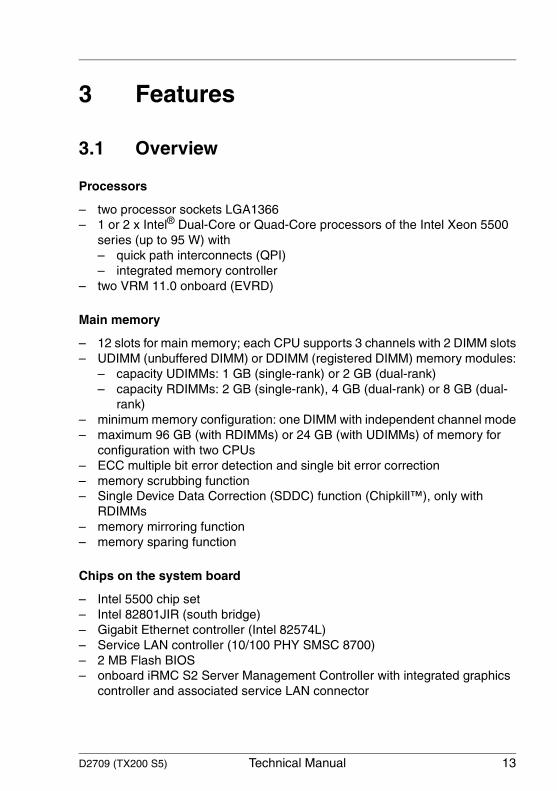
Processors
– two processor sockets LGA1366– 1 or 2 x Intel® Dual-Core or Quad-Core processors of the Intel Xeon 5500
series (up to 95 W) with– quick path interconnects (QPI)– integrated memory controller
– two VRM 11.0 onboard (EVRD)
Main memory
– 12 slots for main memory; each CPU supports 3 channels with 2 DIMM slots– UDIMM (unbuffered DIMM) or DDIMM (registered DIMM) memory modules:
– capacity UDIMMs: 1 GB (single-rank) or 2 GB (dual-rank)– capacity RDIMMs: 2 GB (single-rank), 4 GB (dual-rank) or 8 GB (dual-
rank)– minimum memory configuration: one DIMM with independent channel mode– maximum 96 GB (with RDIMMs) or 24 GB (with UDIMMs) of memory for
configuration with two CPUs– ECC multiple bit error detection and single bit error correction– memory scrubbing function– Single Device Data Correction (SDDC) function (Chipkill™), only with
RDIMMs– memory mirroring function– memory sparing function
Chips on the system board
– Intel 5500 chip set – Intel 82801JIR (south bridge)– Gigabit Ethernet controller (Intel 82574L)– Service LAN controller (10/100 PHY SMSC 8700)– 2 MB Flash BIOS– onboard iRMC S2 Server Management Controller with integrated graphics
controller and associated service LAN connector
14 Technical Manual D2709 (TX200 S5)
Overview Features
– 16 MB SPI Flash (code) and 2 MB SPI Flash (data) for iRMC S2– 32Mx16-533 DDR2 SRAM for iRMC S2– Thermal and system management controller (ADT7462)
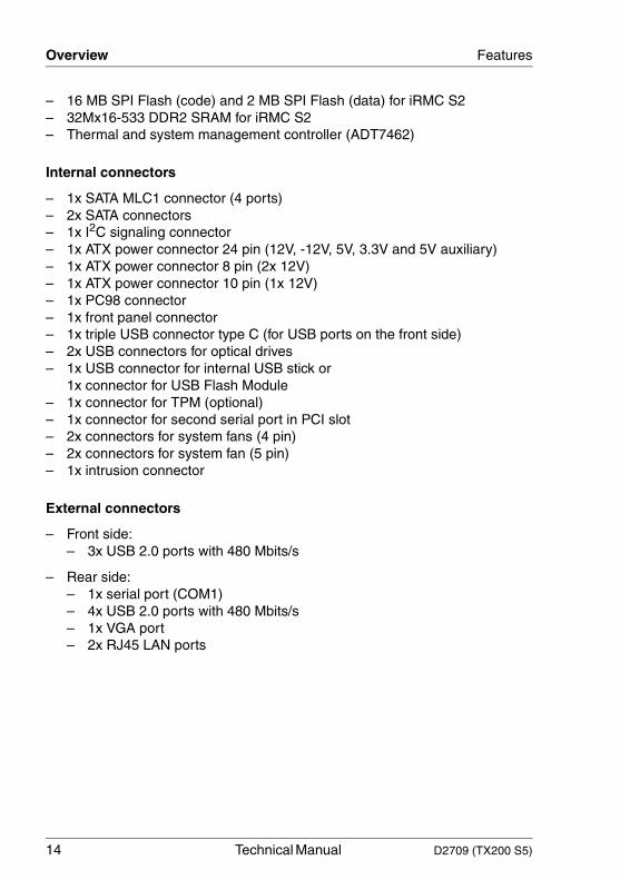
Internal connectors
– 1x SATA MLC1 connector (4 ports)– 2x SATA connectors– 1x I2C signaling connector– 1x ATX power connector 24 pin (12V, -12V, 5V, 3.3V and 5V auxiliary)– 1x ATX power connector 8 pin (2x 12V)– 1x ATX power connector 10 pin (1x 12V)– 1x PC98 connector– 1x front panel connector– 1x triple USB connector type C (for USB ports on the front side)– 2x USB connectors for optical drives– 1x USB connector for internal USB stick or
1x connector for USB Flash Module– 1x connector for TPM (optional)– 1x connector for second serial port in PCI slot– 2x connectors for system fans (4 pin)– 2x connectors for system fan (5 pin)– 1x intrusion connector
External connectors
– Front side:– 3x USB 2.0 ports with 480 Mbits/s
– Rear side:– 1x serial port (COM1) – 4x USB 2.0 ports with 480 Mbits/s– 1x VGA port– 2x RJ45 LAN ports
D2709 (TX200 S5) Technical Manual 15
Features Overview
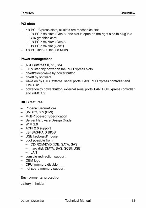
PCI slots
– 5 x PCI-Express slots, all slots are mechanical x8:– 2x PCIe x8 slots (Gen2), one slot is open on the right side to plug in a
x16 graphics card– 2x PCIe x4 slots (Gen2)– 1x PCIe x4 slot (Gen1)
– 1 x PCI slot (32 bit / 33 MHz)
Power management
– ACPI (states S0, S1, S5)– 3.3 V standby power on the PCI Express slots– on/off/sleep/wake by power button– on/off by software– wake on by RTC, external serial ports, LAN, PCI Express controller and
iRMC S2– power on by power button, external serial ports, LAN, PCI Express controller
and iRMC S2
BIOS features
– Phoenix SecureCore– SMBIOS 2.5 (DMI)– MultiProcessor Specification– Server Hardware Design Guide– WfM 2.0– ACPI 2.0 support– LSI SAS/RAID BIOS– USB keyboard/mouse– boot possible from:
– CD-ROM/DVD (IDE, SATA, SAS)– hard disk (SATA, SAS, SCSI, USB)– LAN
– console redirection support– OEM logo– CPU, memory disable– hot spare memory support
Environmental protection
battery in holder
16 Technical Manual D2709 (TX200 S5)
Overview Features
Form factor
SSI EEB Baseboard 307 x 330 mm
CSS (Customer Self Service)
This system board supports the CSS functionality. You will find a description of CSS functionality in the operating manual of your server.
USB Flash Module (option)
The system board can be equipped with an USB Flash Module (UFM) by the manufacturer or by an add-on kit. The module can be used as optional memory for software (e.g. VMware) or as a software dongle.
TPM (option)
The system board can be equipped with a TPM (Trusted Platform Module) by the manufacturer or by an add-on kit. This module enables programs from third party manufacturers to store key information (e.g. drive encryption using Windows Bitlocker Drive Encryption).
The TPM is activated via the BIOS system (for more information, refer to the BIOS manual).
V CAUTION!
– When using the TPM, note the program descriptions provided by the third party manufacturers.
– You must also create a backup of the TPM content. To do this, follow the third party manufacturer's instructions. Without this backup, if the TPM or the system board is faulty you will not be able to access your data.
– If a failure occurs, please inform your service about the TPM activation before it takes any action, and be prepared to provide them with your backup copies of the TPM content.
D2709 (TX200 S5) Technical Manual 17
Features Main memory
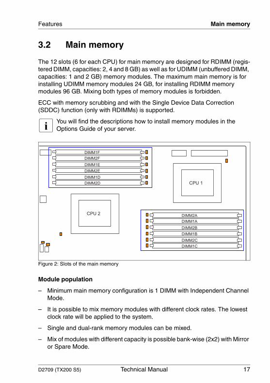
3.2 Main memory
The 12 slots (6 for each CPU) for main memory are designed for RDIMM (regis-tered DIMM, capacities: 2, 4 and 8 GB) as well as for UDIMM (unbuffered DIMM, capacities: 1 and 2 GB) memory modules. The maximum main memory is for installing UDIMM memory modules 24 GB, for installing RDIMM memory modules 96 GB. Mixing both types of memory modules is forbidden.
ECC with memory scrubbing and with the Single Device Data Correction (SDDC) function (only with RDIMMs) is supported.
I You will find the descriptions how to install memory modules in the Options Guide of your server.
Figure 2: Slots of the main memory
Module population
– Minimum main memory configuration is 1 DIMM with Independent Channel Mode.
– It is possible to mix memory modules with different clock rates. The lowest clock rate will be applied to the system.
– Single and dual-rank memory modules can be mixed.
– Mix of modules with different capacity is possible bank-wise (2x2) with Mirror or Spare Mode.
DIMM1F
DIMM2F
DIMM1E
DIMM2E
DIMM1D
DIMM2D
DIMM2A
DIMM1A
DIMM2B
DIMM1B
DIMM2C
DIMM1C
CPU 1
CPU 2

18 Technical Manual D2709 (TX200 S5)
Main memory Features
– The assignment of the DIMM slots to the banks and channels is printed on the system board.
– Install memory modules within a channel in descending order of capacity: higher capacity in black slot, lower capacity in blue slot.
Possible population in different modes:
Figure 3: Possible population in different modes
Independent Channel Mode
– Allows population of all channels in any order. Related to the channels (A-F) DIMM1 must be populated first.
– Works with DIMMs of different clock rates and applies the lowest clock rate.
Mirrored Channel Mode
– Requires identical modules on the channels A & B (CPU 1) and on D & E (CPU 2).
– Half of the capacity is used for the mirroring — only the half of the installed main memory is available for the applications.
– Channel C (CPU 1) respectively channel F (CPU 2) are not available in this mode.
Legend:
required
required, if 2nd CPU is configured
optional, same type in bank per CPU
optional, any type
not usable
CPU 2
CPU 1
CPU 2
DIMM 1F
DIMM 1E
DIMM 1D
DIMM 2E
DIMM 2D
DIMM 2F
Independent
Channel Mode
Mirrored
Channel Mode
Performance
Channel ModeSpare
Channel Mode
CPU 1
DIMM 1A
DIMM 2A
DIMM 2B
DIMM 2C
DIMM 1C
DIMM 1B
DIMM 1F
DIMM 1E
DIMM 1D
DIMM 2E
DIMM 2D
DIMM 2F
DIMM 1A
DIMM 2A
DIMM 2B
DIMM 2C
DIMM 1C
DIMM 1B
* Mirror
*
*
*
*
CPU 1
CPU 2
DIMM 1F
DIMM 1E
DIMM 1D
DIMM 2E
DIMM 2D
DIMM 2F
DIMM 1A
DIMM 2A
DIMM 2B
DIMM 2C
DIMM 1C
DIMM 1B
CPU 1
CPU 2
DIMM 1F
DIMM 1E
DIMM 1D
DIMM 2E
DIMM 2D
DIMM 2F
DIMM 1A
DIMM 2A
DIMM 2B
DIMM 2C
DIMM 1C
DIMM 1B
* Spare
*
*
*
*

D2709 (TX200 S5) Technical Manual 19
Features Main memory
Performance Channel Mode
– Requires identical modules on all channels of each bank per CPU.
Spare Channel Mode
– Requires identical modules on all channels of each bank per CPU.
– One third of the capacity is used as spare range — this means the main memory for the applications is reduced to two third.
20 Technical Manual D2709 (TX200 S5)
PCI slots Features
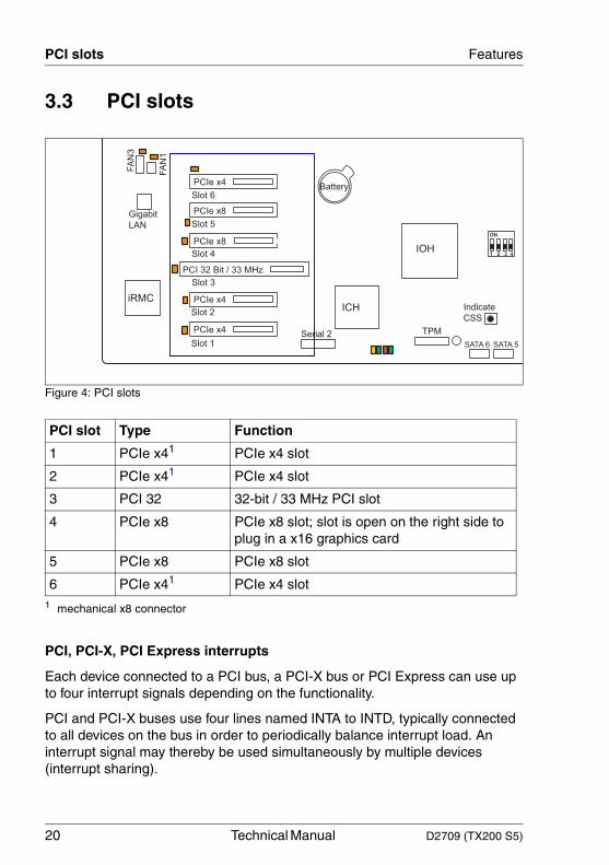
3.3 PCI slots
Figure 4: PCI slots
PCI, PCI-X, PCI Express interrupts
Each device connected to a PCI bus, a PCI-X bus or PCI Express can use up to four interrupt signals depending on the functionality.
PCI and PCI-X buses use four lines named INTA to INTD, typically connected to all devices on the bus in order to periodically balance interrupt load. An interrupt signal may thereby be used simultaneously by multiple devices (interrupt sharing).
PCI slot Type Function
1 PCIe x41
1 mechanical x8 connector
PCIe x4 slot
2 PCIe x41 PCIe x4 slot
3 PCI 32 32-bit / 33 MHz PCI slot
4 PCIe x8 PCIe x8 slot; slot is open on the right side to plug in a x16 graphics card
5 PCIe x8 PCIe x8 slot
6 PCIe x41 PCIe x4 slot
Slot 3
Slot 2
Slot 1
iRMC
Battery
Slot 4
Slot 5
Slot 6
FA
N3
FA
N1
PCI 32 Bit / 33 MHz
PCIe x4
PCIe x4
PCIe x4
PCIe x8
PCIe x8
Serial 2
Gigabit
LANON
1 2 3 4IOH
SATA 6 SATA 5
Indicate
CSSICH
TPM
D2709 (TX200 S5) Technical Manual 21
Features PCI slots
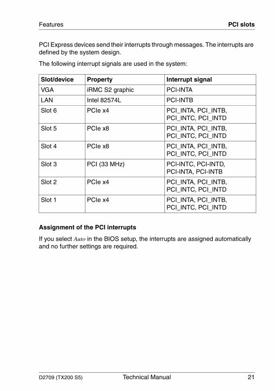
PCI Express devices send their interrupts through messages. The interrupts are defined by the system design.
The following interrupt signals are used in the system:
Assignment of the PCI interrupts
If you select Auto in the BIOS setup, the interrupts are assigned automatically and no further settings are required.
Slot/device Property Interrupt signal
VGA iRMC S2 graphic PCI-INTA
LAN Intel 82574L PCI-INTB
Slot 6 PCIe x4 PCI_INTA, PCI_INTB, PCI_INTC, PCI_INTD
Slot 5 PCIe x8 PCI_INTA, PCI_INTB, PCI_INTC, PCI_INTD
Slot 4 PCIe x8 PCI_INTA, PCI_INTB, PCI_INTC, PCI_INTD
Slot 3 PCI (33 MHz) PCI-INTC, PCI-INTD, PCI-INTA, PCI-INTB
Slot 2 PCIe x4 PCI_INTA, PCI_INTB, PCI_INTC, PCI_INTD
Slot 1 PCIe x4 PCI_INTA, PCI_INTB, PCI_INTC, PCI_INTD
22 Technical Manual D2709 (TX200 S5)
Screen resolution Features
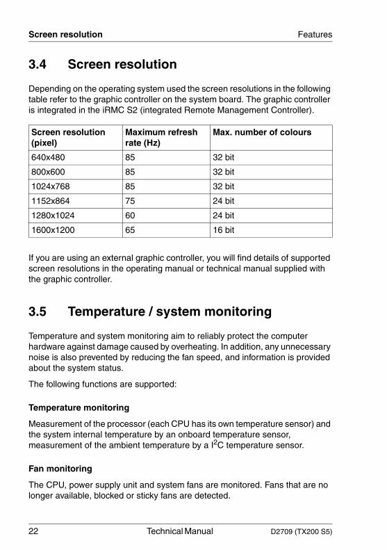
3.4 Screen resolution
Depending on the operating system used the screen resolutions in the following table refer to the graphic controller on the system board. The graphic controller is integrated in the iRMC S2 (integrated Remote Management Controller).
If you are using an external graphic controller, you will find details of supported screen resolutions in the operating manual or technical manual supplied with the graphic controller.
3.5 Temperature / system monitoring
Temperature and system monitoring aim to reliably protect the computer hardware against damage caused by overheating. In addition, any unnecessary noise is also prevented by reducing the fan speed, and information is provided about the system status.
The following functions are supported:
Temperature monitoring
Measurement of the processor (each CPU has its own temperature sensor) and the system internal temperature by an onboard temperature sensor, measurement of the ambient temperature by a I2C temperature sensor.
Fan monitoring
The CPU, power supply unit and system fans are monitored. Fans that are no longer available, blocked or sticky fans are detected.
Screen resolution (pixel)
Maximum refresh rate (Hz)
Max. number of colours
640x480 85 32 bit
800x600 85 32 bit
1024x768 85 32 bit
1152x864 75 24 bit
1280x1024 60 24 bit
1600x1200 65 16 bit
D2709 (TX200 S5) Technical Manual 23
Features Temperature / system monitoring
Fan control
The fans are regulated according to temperature.
Sensor monitoring
The removal of, or a fault in, a temperature sensor is detected. Should this happen all fans monitored by this sensor run at maximum speed, to achieve the greatest possible protection of the hardware.
Voltage monitoring
When voltage exceeds warning level high or falls below warning level low an alert will be generated.
Cover monitoring
Unauthorized opening of the cover is detected, even when the system is switched off. However, this will only be indicated when the system is switched on again.
System Event Log (SEL)
All monitored events of the system board are signalized via the Global Error LED and recorded in the System Event Log. They could be retrieved in the BIOS Setup or via the ServerView Operations Manager.
PRIMERGY Local Diagnostic LEDs
Optical signaling through the LEDs on the system board identifies defective modules and components (CSS functionality) as well as gaining information on the PDA (Prefailure Detection and Analysis).
24 Technical Manual D2709 (TX200 S5)
Connectors and indicators Features
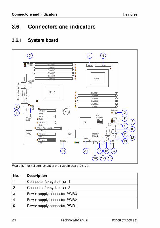
3.6 Connectors and indicators
3.6.1 System board
Figure 5: Internal connectors of the system board D2709
No. Description
1 Connector for system fan 1
2 Connector for system fan 3
3 Power supply connector PWR3
4 Power supply connector PWR2
5 Power supply connector PWR1
VG
A
Slot 3
Slot 2
Slot 1
DIMM1F
DIMM2F
DIMM1E
DIMM2E
DIMM1D
DIMM2D
iRMC
ON
1 2 3 4
Battery
Exte
rnal connecto
rs
Slot 4
Slot 5
Slot 6
Service
LAN
Serial 1
Serv
ice
LA
N 1
US
B 8
/7
IOH
PWR1PWR3 PWR2
FA
N3
FA
N1
FAN4F
rontp
anel
IntrusionU
SB
1
AU
XU
SB
2
AU
X
DIP
switchesP
C98
SATA 6 SATA 5
SA
TA
MLC
1
PCI 32 Bit / 33 MHz
PCIe x4
PCIe x4
PCIe x4
Indicate
CSS
LA
N 2
US
B 4
/5
PCIe x8
PCIe x8
ICH
Serial 2
Gigabit
LAN
DIMM2A
DIMM1A
DIMM2B
DIMM1B
DIMM2C
DIMM1C
CPU 1
CPU 2
SM
B
US
B F
ront
FA
N2
UFMTPM
USB
stick
1
2
3 4 5
6
78
109
1211
13
14
15
16
17
18
19
2021

D2709 (TX200 S5) Technical Manual 25
Features Connectors and indicators
6 Intrusion connector
7 Connector for system fan 4
8 Connector for system fan 2
9 USB1 connector
10 Front panel connector
11 USB2 connector
12 Power supply connector PC98
13 Triple USB connector for USB on the front side
14 I2C signal connector
15 Connector for USB stick
16 SATA MLC1 connector (4 port)
17 Connector for USB Flash Module
18 SATA 5 connector
19 SATA 6 connector
20 Connector for TPM
21 Connector for second serial interface
No. Description
26 Technical Manual D2709 (TX200 S5)
Connectors and indicators Features
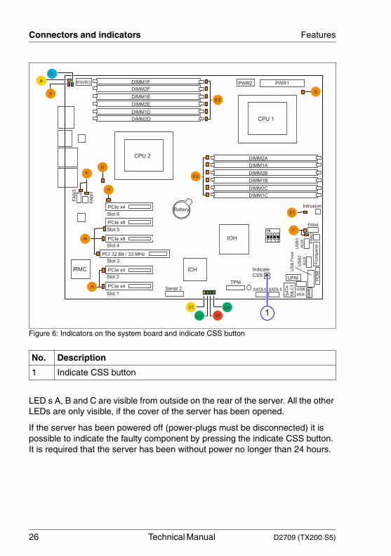
Figure 6: Indicators on the system board and indicate CSS button
LED s A, B and C are visible from outside on the rear of the server. All the other LEDs are only visible, if the cover of the server has been opened.
If the server has been powered off (power-plugs must be disconnected) it is possible to indicate the faulty component by pressing the indicate CSS button. It is required that the server has been without power no longer than 24 hours.
No. Description
1 Indicate CSS button
Slot 3
Slot 2
Slot 1
DIMM1F
DIMM2F
DIMM1E
DIMM2E
DIMM1D
DIMM2D
iRMC
ON
1 2 3 4
Battery
Slot 4
Slot 5
Slot 6
IOH
PWR1PWR3 PWR2
FA
N3
FA
N1
FAN4
Fro
ntp
an
el
Intrusion
US
B1
AU
XU
SB
2
AU
X
PC
98
SATA 6 SATA 5S
ATA
ML
C1
PCI 32 Bit / 33 MHz
PCIe x4
PCIe x4
PCIe x4
Indicate
CSS
PCIe x8
PCIe x8
ICH
Serial 2
DIMM2A
DIMM1A
DIMM2B
DIMM1B
DIMM2C
DIMM1C
CPU 1
CPU 2
SM
B
US
B F
ron
t
FA
N2
UFMTPM
USB
stick
1

D2709 (TX200 S5) Technical Manual 27
Features Connectors and indicators
The LEDs have the following meaning:
LED Indicator Meaning
A - GEL(Global Error LED)
orange indicates a prefailure
orange flashing indicates a failure. Reasons for a failure may be:- over temperature measured by one of the sensors- sensor is defective- CPU error- Software detected an error
B - CSS(Customer Self Service)
yellow indicates a prefailure
yellow flashing indicates a failure
C - Identification blue server is identified via the ServerView Operations Manager
D1 - board yellow aux. voltage available
D2 - board green system running
D3 - board red configuration error. The system board will be held in reset. Possible configuration errors are e.g.: old CPU populated, CPUs with different FSB requirements populated, CPU1 not populated
D4 - board green flashing iRMC S2 - server management controller is ok
off / on iRMC S2 not alive
E1 - overall memory
off all memory modules are running
orange at least one memory module is defective
E2 - memory off memory module running
orange memory module failure
F - system fans
off fan running
orange fan failure
G - CPU off CPU okay
orange CPU failure

28 Technical Manual D2709 (TX200 S5)
Connectors and indicators Features
3.6.2 Connector panel
Figure 7: Connector panel
The serial interface COM1 can be used as default interface or to communicate with the iRMC S2.
LAN connectors
The system board is equipped with a Gigabit Ethernet Controller of the type Intel 82574L. The LAN controller supports transmission rates of 10 Mbit/s, 100 Mbit/s and 1 Gbit/s.
H - PCI card off PCI card okay
orange PCI card failure
No. Description
1 Service LAN connector (for iRMC S2 server management function)
2 LAN connector 2
3 USB connectors
4 VGA port
5 Serial interface COM1
6 Global error indicator (orange), CSS indicator (yellow), ID indicator (blue); (description see preceding section)
LED Indicator Meaning
456
1 2
3
D2709 (TX200 S5) Technical Manual 29
Features Connectors and indicators
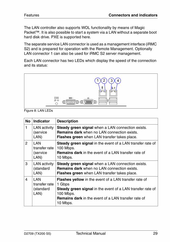
The LAN controller also supports WOL functionality by means of Magic Packet™. It is also possible to start a system via a LAN without a separate boot hard disk drive. PXE is supported here.
The separate service LAN connector is used as a management interface (iRMC S2) and is prepared for operation with the Remote Management. Optionally LAN connector 1 can also be used for iRMC S2 server management.
Each LAN connector has two LEDs which display the speed of the connection and its status:
Figure 8: LAN LEDs
No Indicator Description
1 LAN activity (service LAN)
Steady green signal when a LAN connection exists.Remains dark when no LAN connection exists.Flashes green when LAN transfer takes place.
2 LAN transfer rate (service LAN)
Steady green signal in the event of a LAN transfer rate of 100 Mbps.Remains dark in the event of a LAN transfer rate of 10 Mbps.
3 LAN activity (standard LAN)
Steady green signal when a LAN connection exists.Remains dark when no LAN connection exists.Flashes green when LAN transfer takes place.
4 LAN transfer rate (standard LAN)
Flashes yellow in the event of a LAN transfer rate of 1 GbpsSteady green signal in the event of a LAN transfer rate of 100 Mbps.Remains dark in the event of a LAN transfer rate of 10 Mbps.
1 2 3 4
30 Technical Manual D2709 (TX200 S5)
Connectors and indicators Features
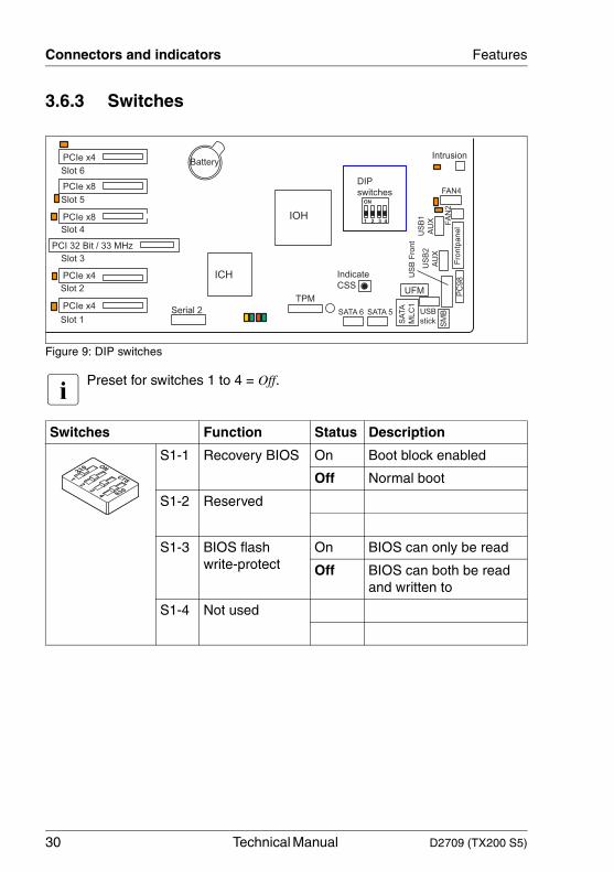
3.6.3 Switches
Figure 9: DIP switches
I Preset for switches 1 to 4 = Off.
Switches Function Status Description
S1-1 Recovery BIOS On Boot block enabled
Off Normal boot
S1-2 Reserved
S1-3 BIOS flash write-protect
On BIOS can only be read
Off BIOS can both be read and written to
S1-4 Not used
Slot 3
Slot 2
Slot 1
Battery
Slot 4
Slot 5
Slot 6
PCI 32 Bit / 33 MHz
PCIe x4
PCIe x4
PCIe x4
PCIe x8
PCIe x8
Serial 2
ON
1 2 3 4IOH
FAN4
Fro
ntp
an
el
Intrusion
US
B1
AU
XU
SB
2
AU
X
DIP
switches
PC
98
SATA 6 SATA 5
SA
TA
ML
C1
Indicate
CSSICH
SM
B
US
B F
ron
t
FA
N2
UFMTPM
USB
stick

D2709 (TX200 S5) Technical Manual 31
4 Replacing the lithium batteryIn order to save the system information permanently, a lithium battery is installed to provide the CMOS-memory with a current. When the charge is too low or the battery is empty, a corresponding error message is provided. The lithium battery must then be replaced.
V The lithium battery must be replaced with an identical battery or a battery type recommended by the manufacturer (CR2450).
Do not throw lithium batteries into the trash can. It must be disposed of in accordance with local regulations concerning special waste.
Make sure that you insert the battery the right way round. The plus pole must be on the top!
Figure 10: Replacing the lithium battery
Ê Press the locking spring into direction of the arrow (1), so that the lithium battery jumps out of its socket.
Ê Remove the battery (2).
Ê Insert a new lithium battery of the same type into the socket (3) and (4).
1
2
3
4


D2709 (TX200 S5) Technical Manual 33
AbbreviationsThe technical terms and abbreviations given below represent only a selection of the full list of common technical terms and abbreviations.
Not all technical terms and abbreviations listed here are valid for the described system board.
ACPIAdvanced Configuration and Power Interface
ASR&RAutomatic Server Recovery and Restart
ATAAdvanced Technology Attachment
BBUBattery Backup Unit
BIOSBasic Input Output System
BMCBaseboard Management Controller
CMOSComplementary Metal Oxide Semiconductor
COMCOMmunication port
CRUCustomer Replaceable Unit
CSSCustomer Self Service
CPUCentral Processing Unit

34 Technical Manual D2709 (TX200 S5)
Abbreviations
DDRDouble Data Rate
DIMMDual In-line Memory Module
DIPDual In-line Package
DMIDesktop Management Interface
DMADirect Memory Access
DRAMDynamic Random Access Memory
ECCError Correction Code
EEPROMElectrical Erasable Programmable Read Only Memory
EPROMErasable Programmable Read Only Memory
EMRLEmbedded RAID Logic
ESDElectrostatic Discharge
EVRDEnterprise Voltage Regulator Down
FBDFully Buffered DIMM
HDDHard Disk Drive
D2709 (TX200 S5) Technical Manual 35
Abbreviations
HPCHot-plug Controller
ICEIn Circuit Emulation
IDEIntegrated (intelligent) Drive Electronics
IMEIntegrated Mirror Enhanced
IOOPIntelligent Organization Of PCI
IPMBIntelligent Platform Management Bus
IPMIIntelligent Platform Management Interface
iRMCintegrated Remote Management Controller
LANLocal Area Network
LEDLight Emitting Diode
MCHMemory Controller Hub
MPSMulti Processor Specification
NMINon Maskable Interrupt
NOSNetwork Operating System
36 Technical Manual D2709 (TX200 S5)
Abbreviations
NVRAMNon Volatile RAM
ODDOptical Disc Drive
OEMOriginal Equipment Manufacturer
OHCIOpen Host Controller Interface
OSOperating System
PCIPeripheral Components Interconnect
PDAPrefailure Detection and Analyzing
PIOProgrammed Input Output
PLDProgrammable Logic Device
POSTPower-On Self Test
PS(U)Power Supply (Unit)
PWMPulse Wide Modulation
PXEPreboot eXecution Environment
RAIDRedundant Array of Inexpensive Disks
D2709 (TX200 S5) Technical Manual 37
Abbreviations
RAMRandom Access Memory
RSBRemote Service Board
RSTReSeT
RTCReal Time Clock
SASSerial Attached SCSI
SATASerial ATA
SCSISmall Computer Systems Interface
SDDCSingle Device Data Correction
SDRAMSynchronous Dynamic Random Access Memory
SHDGServer Hardware Design Guide
SHPCStandard Hot Plug Controller
SMBSystem Management Bus
SMMServer Management Mode
SMPSymmetrically Multi Processing
38 Technical Manual D2709 (TX200 S5)
Abbreviations
SSDSolid-State Drive
TPMTrusted Platform Module
UHCIUnified Host Controller Interface
USBUniversal Serial Bus
VGAVideo Graphics Adapter
VRDVoltage Regulator Down
VRMVoltage Regulator Module
WfMWired for Management
WOLWake up On LAN