sysque pac - building databuilding-data.net/bd-download/manual - sysque_pac.pdf · sysque® pac...
TRANSCRIPT

SysQue® PAC
Duct Manufacturing downloading
and integration with Autodesk
Fabrication CAMduct, Vicon, and
Vulcan
This document is based on:
SysQue® PAC 2015, 2016, and 2017

SYSQUE.COM 2
SUMMARY
This document provides detailed information on how to use SysQue® PAC to manufacture and order your duct
from your SysQue® Systems BIM models to multiple different CAM stations with a variety of options along the
way.
DOCUMENT TOPICS
SysQue® PAC Main form and basics
Configuration for Autodesk Fabrication CAMduct and sending a job
Configuration for Vulcan and sending a job
Configuration for Vicon and sending a job
Excel report exporting and export format options
Connector mapping options for Autodesk Fabrication CAMduct
Specification mapping options for Autodesk Fabrication CAMduct
Connector mapping options for Vulcan
Specification mapping options for Vulcan
Connector mapping options for Vicon
Specification mapping options for Vicon
Autodesk Fabrication CAMduct station setup and SysQue® PAC Integration including Custom Connectors
Autodesk Fabrication CAMduct station Scripting Utility use and setup
Vulcan SysQue® PAC file import
Vicon SysQue® PAC file import
SysQue® PAC Add Hole option with Autodesk Fabrication CAMduct for Taps and Access Doors
SysQue® PAC List of available duct patterns for manufacturing integration
SysQue® Systems Duct, SysQue® PAC & TSI Duct Standard Specifications

SYSQUE.COM 3
SysQue® PAC Main Form and Basics
Using PAC is very easy. To start, you open the SysQue® PAC window by clicking on the PAC icon in the
SysQue® Ribbon panel.
This will open the main PAC dialog and will look like this.
From this Dialog you will click on the “Select” button . This will then put you back to your model in a
selection mode. Once you have selected all of the duct you wish to submit with SysQue® PAC PAC, you will
click on
“Finish” .
1
2
2
3

SYSQUE.COM 4
Once the main SysQue® PAC window opens again, you will see that each fitting has a unique tab, and a
populated grid within it showing the details of each instance of that fitting in your selection.
If you want to inspect the actual fitting in the model, you simply highlight the fitting in the grid then click the “Go
to Item” button at the bottom, the main form will minimize and the fitting highlighted will be zoomed in on.
To get back just click on the PAC window again on your taskbar. Alternatively, if you want to zoom into a duct
fitting by using the Item Number, you can check the “Locate Item By Item Number” at the bottom and
type the known item number into the now visible text field, then when you click the “Go To Item” again, it will
find and zoom into the duct that has this Item Number.
The Job Information area at the top of the form is where you will assemble the name of the file(s) that get
generated by PAC. The Job Number, the Level/Floor, and the System fields are connected by hyphens to
create the file name that will be used. Filling these out is mandatory at this time for the file to generate for you.
The Output Format and Configuration area of the form are very important. It is vital that you select the
correct Output Format to match what your Shop will be using. The Configuration is important because there
are different units, as well as different standards for different geographical regions in the world for sheet metal
4
5
4
6
4
7
4
3
4 5
4
6
4
7
4
8
4
9
4
10
4
11
4
12
4
SYSQUE.COM 5
fabrication. Once you select the correct Output format and Configuration, and send your first Job, these
settings will be saved for you and remain each time SysQue® PAC opens.
The Dashboard is important, it lets you know that you have a successful connection to the SysQue®
PAC cloud which is necessary to be able to get a processed file for manufacturing use.
The Include Items Processed Previously option is a built in safety feature. Whenever you send duct
through SysQue® PAC, the items are flagged as “Processed”, then when this option is not checked, SysQue®
PAC will not allow you to send the same duct again by making the ones that have been processed non-
selectable. However, if you still want to send the same duct, you just tick the check box and the ones
processed prior become selectable again.
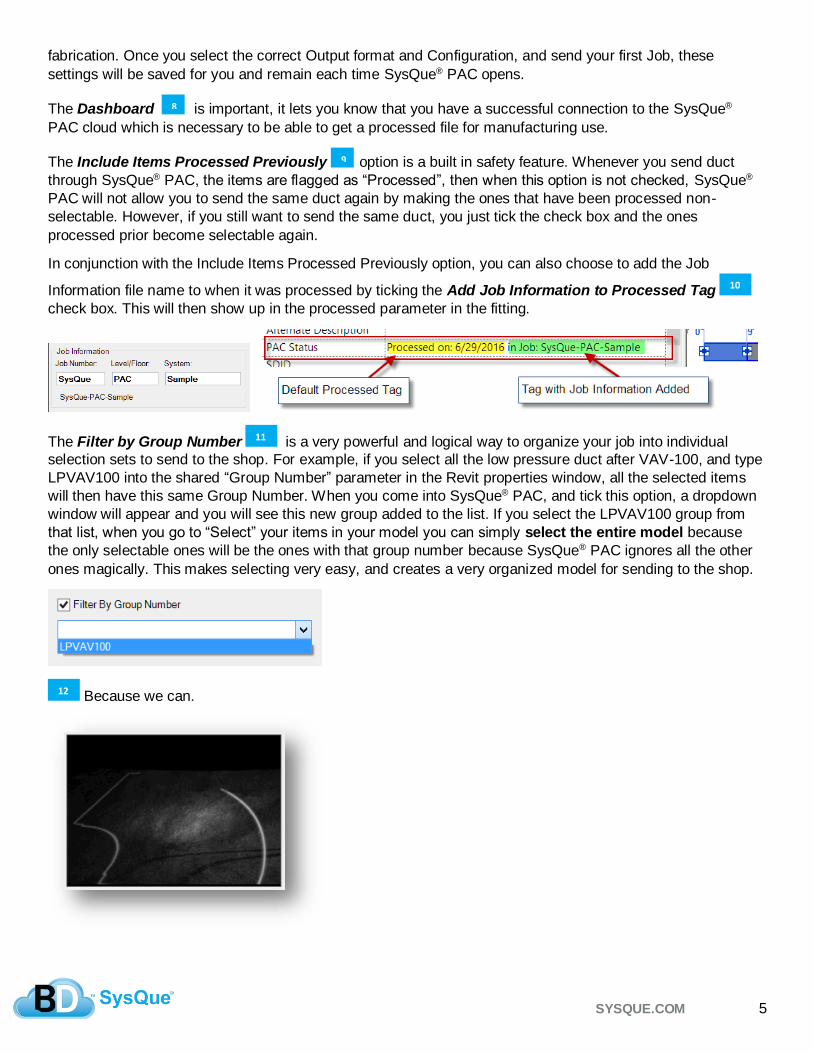
In conjunction with the Include Items Processed Previously option, you can also choose to add the Job
Information file name to when it was processed by ticking the Add Job Information to Processed Tag
check box. This will then show up in the processed parameter in the fitting.
The Filter by Group Number is a very powerful and logical way to organize your job into individual
selection sets to send to the shop. For example, if you select all the low pressure duct after VAV-100, and type
LPVAV100 into the shared “Group Number” parameter in the Revit properties window, all the selected items
will then have this same Group Number. When you come into SysQue® PAC, and tick this option, a dropdown
window will appear and you will see this new group added to the list. If you select the LPVAV100 group from
that list, when you go to “Select” your items in your model you can simply select the entire model because
the only selectable ones will be the ones with that group number because SysQue® PAC ignores all the other
ones magically. This makes selecting very easy, and creates a very organized model for sending to the shop.
Because we can.
8
4
9
4
10
4
11
4
12
4

SYSQUE.COM 6
Configuration for Autodesk Fabrication CAMduct and Sending a Job
There are 3 Configuration options for CAMduct, they are based on geographical industry standards and their
units (Imperial or Metric). It is very important that you send your job with the correct Configuration option.
The Output Format will determine the file type that is generated, for CAMduct this will be .MAJ file type that
can be opened and used natively with Autodesk Fabrication CAMduct to download your duct to your Plasma
tables and/or Decoilers.
Configuration for Vulcan and Sending a Job
There are 3 Configuration options for Vulcan, they are based on geographical industry standards and their
units (Imperial or Metric). It is very important that you send your job with the correct Configuration option.
The Output Format will determine the file type that is generated, for Vulcan this will be 2 files, one is the
import file with the details of your duct and fittings, the other is a security signature file added for your
protection to ensure the file was generated by an authorized third party developer and that it was not tampered
with during electronic transfer. Editing the import file will cause the import to fail. The import file will be used to
import the SysQue duct and Fittings into Vulcan to download your SysQue Duct and Fittings to your Plasma
tables and/or Decoilers, the signature file needs to remain with the import file, in the same folder.
Configuration for Vicon and Sending a Job
There are 3 Configuration options for Vicon, they are based on geographical industry standards and their
units (Imperial or Metric). It is very important that you send your job with the correct Configuration option.
The Output Format will determine the file type that is generated, for Vicon this will be .txt file type that can be
imported into your Vicon platform to download your SysQue Duct and Fittings to your Plasma tables and/or
Decoilers.

SYSQUE.COM 7
Excel report exporting and export format options
SysQue® PAC gives you the option to export your Duct and Fitting selection to Excel to use for reporting. There
are also some options for formatting this report, hiding or showing columns as well as grouped filters .
By default, all columns are on, but if you use the Excel Export Settings, you can choose to simplify your report and
remove columns that you do not need for your report process. Below is an example of the default before, and then after
the columns in the above example have been hidden. This setting is saved and remembered each time you make
changes to it, so once you have it the way you want it will remain that way.
1
4 2
4
3
4
2
4
2
4
1
4

SYSQUE.COM 8
The SysQue® PAC interface allows you to use what are called “Group Filters”. These are used simply by dragging a
column header to the top that you would like to group by. These will let you further customize your reported output into
logical groupings for your manufacturing and/or ordering process. The example below shows how you can break up your
straight duct report into:
Non-Coil duct without liner , Non-Coil duct with liner , Coil duct without liner , and Coil duct with liner
4
4
5
4
6
4
7
4
3
4
5
4
4
4
7
4
6
4

SYSQUE.COM 9
Connector Mapping Options for Autodesk Fabrication CAMduct
SysQue® PAC offers the ability for you to specify what connector you want to map your SysQue Duct connector to
within the list of TSI Standard connectors. (Mapping to custom connectors is also supported, and is covered in this document in the topic
labeled: “Autodesk Fabrication CAMduct station using SysQue® Systems Duct Custom Connectors”)
To MAP your connectors, within the main SysQue® PAC window, you will go to File , and click on Specification and
Connector Mapping . Once in the dialog, select the Connector Map tab , you will go down the list on the Left and
for each, select from the dropdown on the Right the desired Fabrication connector you want to use . It is
important you select a “like” connector, meaning do not select for example a TDC or Companion Flange connector if the
SysQue connector is based on a Bead and Crimp connection method. Most of these will be setup for you out of the box,
and will only need reviewed for specific workflows that might differ slightly based on your Manufacturing standards.
Note: This dialog will reflect the settings based on what output you have set currently, CAMduct, Vulcan, or Vicon, so be
sure that CAMduct is the Output Format selected .
Once you have completed this mapping, the SysQue named connector will be replaced with the Autodesk Fabrication
named connector during the cloud processing. In this example, the SysQue “Bead and Crimp” connector was replaced
with “Bead & Crimp” within the returned .MAJ file. (The .MAJ file is the native file format for Autodesk Fabrication CAMduct.)
1
4 2
4
3
4 4
4
5
4
6
4
2
4
1
4 3
4 4
4
5
4 6
4

SYSQUE.COM 10
Specification Mapping Options for Autodesk Fabrication CAMduct
SysQue® PAC allows you map your SysQue® Systems Duct Specification to a TSI Duct Standard Specification within
the Autodesk Fabrication CAMduct software. (Mapping to custom Specifications is also supported, and is covered in this document in the
topic labeled: “Autodesk Fabrication CAMduct station SysQue® Scripting Utility use and setup”)
To MAP your Specifications, within the main SysQue® PAC window, you will go to File , and click on Specification
and Connector Mapping . Once in the dialog, select the Spec Map tab , you will go down the list on the Left and
for each, select from the dropdown on the Right the matching TSI Duct Standard Specification you want to use .
Most of these will be setup for you out of the box, and will only need reviewed for specific workflows that might differ
slightly based on your Manufacturing standards.
Note: This dialog will reflect the settings based on what output you have set currently, CAMduct, Vulcan, or Vicon, so be
sure that CAMduct is the Output Format selected .
Once you have completed this mapping, the SysQue named Specification will be replaced with the TSI Duct Standard
named Specification during the cloud processing. In the below example, the SysQue “2WG-Galv-Str-TDC” Specification
was replaced with “+2WG TSI-Standard” within the returned .MAJ file. (The .MAJ file is the native file format for Autodesk
Fabrication CAMduct.)
1
4 2
4
3
4 4
4
5
4
6
4
1
4
2
4
3
4 4
4 5
4
6
4

SYSQUE.COM 11
Connector Mapping Options for Vulcan
SysQue® PAC allows you to map your SysQue® Systems Duct Connectors to your specific Connector within your
Vulcan cutting software.
To MAP your connectors, within the main SysQue® PAC window, you will go to File , and click on Specification and
Connector Mapping . Once in the dialog, select the Connector Map tab , you will go down the list on the Left and
for each, type in the name of your connector for each . It is important you type a “like” connector, meaning do not
type for example a TDC or Companion Flange connector if the SysQue connector is based on a Bead and Crimp
connection method.
Note: This dialog will reflect the settings based on what output you have set currently, CAMduct, Vulcan, or Vicon, so be
sure that Vulcan is the Output Format selected .
Once you have completed this mapping, the SysQue named connector will be replaced with your Vulcan named
connector during the cloud processing. In this example, the SysQue “S and Drive” connector was replaced with “SLIP &
DRIVE” within the returned import file. (The import file will be imported into the Vulcan Cutting Software. Note, you will receive 2 files
back, both are required, one is a security signature file that ensures the file integrity since it is transmitted over the cloud. It ensures that the file
was not modified between our cloud and your computer.)
1
4 2
4
3
4 4
4
5
4
1
4
2
4
3
4 4
4
5
4

SYSQUE.COM 12
Specification Mapping Options for Vulcan
SysQue® PAC allows you to map your SysQue® Systems Duct Connectors to your specific Specification within your
Vulcan cutting software.
To MAP your connectors, within the main SysQue® PAC window, you will go to File , and click on Specification and
Connector Mapping . Once in the dialog, select the Spec Map tab , you will go down the list on the Left and for
each, type in the name of your Specification for each .
Note: This dialog will reflect the settings based on what output you have set currently, CAMduct, Vulcan, or Vicon, so be
sure that Vulcan is the Output Format selected .
Once you have completed this mapping, the SysQue named Specification will be replaced with your Specification name
during the cloud processing. In the below example, the SysQue “2WG-Galv-Str-TDC” Specification was replaced with
“2”WG” within the returned .import file. (The import file will be imported into the Vulcan Cutting Software. Note, you will receive 2 files
back, both are required, one is a security signature file that ensures the file integrity since it is transmitted over the cloud. It ensures that the file
was not modified between our cloud and your computer.)
1
4 2
4
3
4 4
4
5
4
1
4
2
4
3
4 4
4
5
4

SYSQUE.COM 13
Connector Mapping Options for Vicon
SysQue® PAC allows you to map your SysQue® Systems Duct Connectors to your specific Connector within your
Vicon cutting software.
To MAP your connectors, within the main SysQue® PAC window, you will go to File , and click on Specification and
Connector Mapping . Once in the dialog, select the Connector Map tab , you will go down the list on the Left and
for each, type in the name of your connector for each . It is important you type a “like” connector, meaning do not
type for example a TDC or Companion Flange connector if the SysQue connector is based on a Bead and Crimp
connection method.
Note: This dialog will reflect the settings based on what output you have set currently, CAMduct, Vulcan, or Vicon, so be
sure that Vicon is the Output Format selected .
Once you have completed this mapping, the SysQue named connector will be replaced with your Vicon named
connector during the cloud processing. In this example, the SysQue “S and Drive” connector was replaced with “SLIP &
DRIVE” within the returned txt file. (The txt file will be imported into the Vulcan Cutting Software.)
1
4 2
4
3
4 4
4
5
4
1
4
2
4
3
4 4
4
5
4

SYSQUE.COM 14
Specification Mapping Options for Vicon
SysQue® PAC allows you to map your SysQue® Systems Duct Connectors to your specific Specification within your
Vicon cutting software.
To MAP your connectors, within the main SysQue® PAC window, you will go to File , and click on Specification
and Connector Mapping . Once in the dialog, select the Spec Map tab , you will go down the list on the Left and
for each, type in the name of your Specification for each .
Note: This dialog will reflect the settings based on what output you have set currently, CAMduct, Vulcan, or Vicon, so be
sure that Vicon is the Output Format selected .
Once you have completed this mapping, the SysQue named Specification will be replaced with your Specification name
during the cloud processing. In the below example, the SysQue “2WG-Galv-Str-TDC” Specification was replaced with “2
WG” within the returned .txt file. (The txt file will be imported into the Vicon Cutting Software.)
1
4 2
4
3
4 4
4
5
4
1
4
2
4
3
4 4
4
5
4
SYSQUE.COM 15
Autodesk Fabrication CAMduct station setup and SysQue® PAC Integration
In order to successfully process a SysQue® PAC processed .MAJ file, you will want to first set up your Autodesk
Fabrication CAMduct database to ensure a successful integration as well as set up any custom modifications you would
like during processing. This is done in 3 steps:
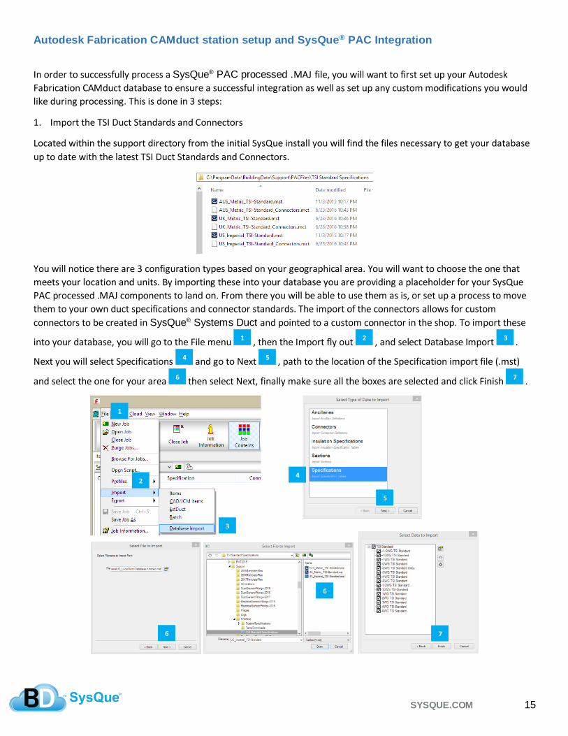
1. Import the TSI Duct Standards and Connectors
Located within the support directory from the initial SysQue install you will find the files necessary to get your database
up to date with the latest TSI Duct Standards and Connectors.
You will notice there are 3 configuration types based on your geographical area. You will want to choose the one that
meets your location and units. By importing these into your database you are providing a placeholder for your SysQue
PAC processed .MAJ components to land on. From there you will be able to use them as is, or set up a process to move
them to your own duct specifications and connector standards. The import of the connectors allows for custom
connectors to be created in SysQue® Systems Duct and pointed to a custom connector in the shop. To import these
into your database, you will go to the File menu , then the Import fly out , and select Database Import .
Next you will select Specifications and go to Next , path to the location of the Specification import file (.mst)
and select the one for your area then select Next, finally make sure all the boxes are selected and click Finish .
1
4
2
4
3
4 4
4
5
4 6
4
7
4
1
4
2
4
3
4
4
4 5
4
6
4
7
4
6
4

SYSQUE.COM 16
This process is repeated for the Connector import, simply select Connectors on the screen after Database Import and
select the correct Connector import for your area, make sure all checkboxes are selected and click on Finish. Your
database is now ready to accept a .MAJ from SysQue® Systems PAC and will have all the place holders needed.
2. Coordinate the custom connectors that may be used in SysQue® Systems Duct with your duct fabrication shop.
During the configuration of your SysQue® Systems Duct, you may determine you would like some additional
connectors that are not part of the pre-defined ones. This is done by duplicating one of the existing ones and giving it an
alias. You can have up to 3 custom connectors for each pre-defined one. For example, if you wanted to create a “1in
Flange In” connector, you could just duplicate the pre-defined RAW connector since the geometry in the model would
be sufficient. When you duplicate this connector using the + within the SysQue® Systems Duct Specification
Settings dialog it becomes RAW-1. You can then give it an alias called “1in Flange In” . You will then notify and
coordinate this with the shop that will manufacture your duct and let them know that “RAW-1” is meant to be a “1in
Flange In” connection. This process would continue for all the custom connectors you wish to create.
The image above is from SysQue® Systems Duct within the Specification Settings located from within the command
dropdown window of SysQue® Systems Duct.
1
4 2
4
1
4 2
4

SYSQUE.COM 17
3. Setup your standard process scripting .cod file.
Your script file will contain standard instructions that will be used every time you process a job received from SysQue®
Systems PAC. It will handle things like locating all “RAW-1” connectors and setting them to your actual “1in Flng In”
connector that is currently used in your shop standard. It can also move your entire job from the TSI Duct Standard
Specifications and Materials to your own shop standard specifications and Materials. To create this .cod Scripting file
please refer to topic “Autodesk Fabrication CAMduct station Scripting Utility use and setup” in this document. This topic will show
you how to setup your CAM station to always use these instruction at processing time assuming you already have
the .cod file created.
From within Autodesk Fabrication CAMduct, you will click on “Setup Processes” . Next you will want to check the
box at the bottom of the next dialog labeled “Execute Script After Process” . Click on the folder icon next to
path to your Script file you have created. And finally click on Open . Note, if you are already using a script in
your process it may be necessary to combine the scripts together or create a new Process specifically for jobs from
SysQue® Systems PAC.
Now, every time you run your process, the script will run and you will get your desired changes that meet your shop’s
manufacturing standards.
1
4 2
4
3
4 4
4
5
4
1
4
2
4
3
4
4
4
5
4

SYSQUE.COM 18
Autodesk Fabrication CAMduct station Scripting Utility use and setup
The SysQue® Script II utility is included in the installation of SysQue® Systems. This utility makes it very easy for you
to customize the integration between SysQue® Systems and your current duct manufacturing shop standards. Most
people do not know how to write in the required scripting language provided as a tool with Autodesk Fabrication
CAMduct, so the SysQue® Script II utility does the script writing for you after you specify what properties you would
like to change.
The SysQue® Script II utility is located within the support directory after installation.
When you launch this application, you will see that the interface is pre-loaded with all the TSI Standards. This makes it
very easy for you to specify what properties you want to generate scripting for. The interface is broken into 4 main
areas. Specifications Mapping , Connector Mapping , Material Mapping , and Options mapping ..
The Save and Open button allow you to save all of your options so you can come back later and modify or add
to the script. The save and open save your options within a .SQPS (SysQue PAC Script) file . Once you make changes
a new .cod script file will need to be generated .
1
4
2
4
3
4
4
4
5
4
6
4 8
4 7
4
1
4
2
4
3
4
4
4
5
4
6
4
7
4
8
4

SYSQUE.COM 19
Specification Mapping
Within Autodesk Fabrication CAMduct, go to the Main Database . In the Main Database go to the Fittings area.
Inside of Fittings click on the Specifications . In Specifications go to the Specification Properties . This properties
window, for the specification you want to map to, will be exactly what you will put into the fields for CAM Group
and CAM Specification . In this example, when an item with “+2WG TSI Standard” Specification with “Galvanized”
material is found, it will be moved to the “+2WG” Specification in the “Duct” group.
Connector Mapping Connector mapping will allow you to change from the SysQue® Systems named connector to your standard like
connector in your database. It is also used to translate the SysQue® Systems Duct Custom connectors. For this you
will coordinate with the modeling team to get their matrix standard for the custom connectors. For example, they may
duplicate the RAW connector and make RAW-1 so that they can have a connector to use for “flanged in” scenarios
such as a duct tap with a grille box attached. Once you know which connector they used and what it intended for, you
would then simply place the exact named connector your shop uses for that scenario such as “1in Flg In” .
1
4 A
4
B
4 C
4
D
4 E
4 F
4
2
4
A
4
B
4
A
4
B
4
C
4
D
4
E
4
F
4 F
4 E
4
B
4 A
4

SYSQUE.COM 20
Material Mapping If you are changing from the TSI Duct Standards to your own Standard Specification then you will want to also make sure
you map to your specific Materials and Material Group as well so that when the items move to the new spec they have a
valid Material to validate on that has specifications for it in your database. To do this you will go to your Main Database
in Autodesk Fabrication CAMduct, click on Fittings , Click on Materials dropdown and locate the Material
you wish to map to, click on that Material’s properties . The Name is what you will place in the CAM Material
Name , and the Group is what you will place in the CAM Group .
Once you generate your script, for each of the items that are found with the SysQue Material Name , they will be
changed to your Material and Group name from your Database .
Option Mapping The Options Mapping area will allow you to actually specify any option in your pattern to meet your manufacturing
standards in your shop. To do this, click on the Select Pattern From List dropdown and locate the SysQue Systems
compatible pattern from the list. Next, type in the exact option name that you want to specify , then type in the
exact value you want for that option . Then, click the Add To List button . When you generate the script, that
option for that pattern will be set to your value when you apply the script at process time. You can specify as many
options for each pattern as you need.
3
4
A
4
B
4
C
4 D
4
E
4 F
4
G
4
H
4
J
4 F
4
H
4 4
4
A
4 B
4 C
4
D
4
H
4
G
4
F
4 E
4
D
4
C
A
4
B
4 A
4
J
4
A
4
B
4 C
A
4
D
4
C
A
4
C
A
4
B
4
A
4

SYSQUE.COM 21
Vulcan SysQue® PAC file import
SysQue® PAC will generate 2 files for your Vulcan import process. One file contains the job with all the duct
instructions, the other is a Signature file that ensures that the import file has not been tampered with between the
cloud and when you actually go to import it. Likewise because of this, if you try to manually modify the txt file, the
import will fail. In order to use the SysQue® import within Vulcan, you must meet some minimum criteria. The screen
capture below gives an overview of this:

SYSQUE.COM 22
Vicon SysQue® PAC file import
SysQue® PAC will generate a single .txt file for you to use to import your duct instructions into your Vicon software. In
order to be able to Import this file into your Vicon station, you must first make sure you have contacted your Plasma
Automation rep or contact and purchase the SysQue import option, as well as ensure they have installed the required
mapping file for this process onto your Vicon station. Once you have enabled your Vicon station you will be able to see
“SysQue” as one of the options under the File Import options.
SysQue® does not support the Vicon software directly so if you have a question regarding the import within the Vicon
interface, please contact Plasma Automation or your Plasma Automation rep. If you do not have a contact, you can go to
www.vicon-machinery.com and click on “Contact Us”.
If you have any questions regarding generating the file necessary for Vicon in the SysQue® PAC interface, please
contact us through Zendesk.

SYSQUE.COM 23
SysQue® PAC Add Hole option for Autodesk Fabrication CAMduct Access Doors and Taps
SysQue® PAC offers the automation to have your separate tap holes and/or access doors automatically get cut out of
the Duct that they are going to be attached to. This feature is only supported for the Autodesk Fabrication CAMduct
workflow. At this time Vulcan and Vicon do not support this unless the duct and tap body are a single fitting/family
already. In order to use this feature you must turn it on inside of SysQue® PAC. Within the SysQue® PAC interface,
go to file and select settings. Within the settings dialog check the option to “Cut Holes in Straights with Taps and/or
Access Doors .
This option is only available for Autodesk Fabrication CAMduct, so be sure you have set your Configuration output to
CAMduct prior to going into settings to see this option.
1
4
2
4
1
4
2
4

SYSQUE.COM 24
SysQue® PAC List of Available Patterns for Manufacturing Integration
The following are the patterns that are supported with SysQue® Systems Duct with SysQue® PAC downloading:
Image SysQue Family Pattern Fabrication CID Vulcan Pattern Vicon Pattern
Rec Straight 866FN=102(Coil), FN=108(Ftg) RectangularStraightWCoilOption
Rec Square Bend 20FN=153- RectangularElbow
Rec Transition 2FN=120- RectangularTransition
Rec Radius Bend 4FN=163- RectangularRadiusElbow
Reducing Elbow Rectangular 3FN=153-(90), FN=162-(0-45) RectangularReducingMiteredElbow
Drop Cheek 320FN=160-(90), FN=166-(0-45) RectangularRadiusReducingOffsetElbow
Rec Square Tap 25FN=4200- RectangularSquareTap
Rec Shoe Tap 7FN=148- RectangularShoeTap
Rectangular Shoe Tap on Round 69FN=1200-(Body), FN=12-(Tap) RectangularShoeTapOnRound
Rectangular Tap on Round 64FN=1200-(Body), FN=12-(Tap) RectangularTapOnRound
Rec Tee 13FN=170- RectangularTee
Rec-Y 14FN=174-(90), FN=178-(45) RectangularWye
Rec Pants 328FN=119- RectangularPants
Radius Offset 330FN=183 RectangularRadiusOffset
Mitered Offset 30FN=187- RectangularMiteredOffset
Rec Cap 12FN=129- RectangularEndCap
Step Down Connector 12Not Supported RectangularStepDownFitting
Rec Y-Side Branch 18FN=192- RectangularSideBranch
Square To Round 8FN=134- SquareToRound
Duct Canvas 166FN=118- RectangularCanvas
SysQue Systems Manufactured Rectangular Duct Patterns

SYSQUE.COM 25
Note: Vulcan fittings get an “i” or a “m” after for Imperial of Metric
Image SysQue Family Pattern Fabrication CID Vulcan Pattern Vicon Pattern
Round Straight 40 & 41FN=300- RoundStraight
Round Gored Elbow 61FN=306- RoundGoredElbow
Round Reducer 51FN=315- RoundReducer
Round Radius Bend 523Not supported RoundRadiusBend
Round Coupling Male 1112Not supported RoundMaleCoupling
Round Tee 851FN=1000- RoundTee
Round Cap 60FN=351- RoundCap
Round Bellmouth Tap 1020FN=4200- RoundBellmouth
Round Shoe Spigot Take-off 871FN=1200 RoundShoeSpigotTakeoff
Round Shoe on Flat 24FN=4200- RoundShoeTapOnFlat
Round Reducer Lateral 850FN=2000-(Body) , FN=1-(Branch) RoundReducerLateral
Round Gored Offset 68FN=319- RoundGoredOffset
Reducing Gored Elbow 142FN=307- RoundReducingGoredElbow
Round Duct Canvas 555FN=313- RoundCanvas
SysQue Systems Manufactured Round Duct Patterns
Image SysQue Family Pattern Fabrication CID Vulcan Pattern Vicon Pattern
Oval Straight 106FN=400- OvalStraight
Oval Gored Bend 106FN=405- OvalGoredElbow
Oval Mitered Bend 106FN=405- OvalMiteredElbow
Oval Reducer 122FN=414- OvalReducer
Oval Coupling Male 1522Not Supported OvalMaleCoupling
Oval Cap 121FN=451- OvalCap
Oval Shoe Spigot Take-off 118FN=2700- OvalShoeSpigotTakeOff
Rectangular to Oval 104FN=141- RectangularToOval
Oval to Round 123FN=414- OvalToRound
SysQue Systems Manufactured Oval Duct Patterns

SYSQUE.COM 26
SysQue® Systems Duct, SysQue® PAC, & TSI Duct Standard Specifications
Technical Sales International has been providing the Mechanical industry with processes, tools, automation,
and best practices for well over a decade worldwide. Given this, we had an excellent opportunity to pull from
the vast pool in the industry to generate our own Duct Standard Specifications. Rather than actually quiz users
on what their best practices were, we instead asked for them to be a part of a massive data initiative and send
us their actual .MAJ files. See, with the .MAJ files we cut out the “opinions” of users of often different answers
within the same company between design and installation. We cut to the chase and wanted to examine what
was actually being manufactured by region worldwide. This let us figure out what pressure classes and
materials were being used, what duct construction was being used within those specifications, all the way
down to connectors, seams, notches, etc.
We condensed all of this great information and built what can be considered the best of breed Duct
Construction Standards for the industry. We then took these and had them reviewed and stamped by
SMACNA. So, with every purchase of SysQue Systems, you get a fully industry accepted configuration of Duct
that is SMACNA approved out of the box.
Customers that go to Autodesk Fabrication CAMduct from SysQue PAC will find that their MAJ that returns is
from these Duct Construction standards. We then give you tools to map from those to any specific construction
standard or process that might differ within your shop.
Customers that use the v200 version of SysQue and draw with the out of the box configuration will be drawing
to real world fittings and construction standards that can be then used further down the process to minimize on
rework and mistakes.
Regards,
Brian K. Gruel
VP-Technology, SysQue