synthesis of mechanical networks: the inerter - automatic -
TRANSCRIPT

1648 IEEE TRANSACTIONS ON AUTOMATIC CONTROL, VOL. 47, NO. 10, OCTOBER 2002
Synthesis of Mechanical Networks: The InerterMalcolm C. Smith, Fellow, IEEE
Abstract—This paper is concerned with the problem of synthesisof (passive) mechanical one-port networks. One of the main con-tributions of this paper is the introduction of a device, which willbe called the inerter, which is the true network dual of the spring.This contrasts with the mass element which, by definition, alwayshas one terminal connected to ground. The inerter allows electricalcircuits to be translated over to mechanical ones in a completelyanalogous way. The inerter need not have large mass. This allowsany arbitrary positive-real impedance to be synthesized mechan-ically using physical components which may be assumed to havesmall mass compared to other structures to which they may be at-tached. The possible application of the inerter is considered to avibration absorption problem, a suspension strut design, and as asimulated mass.
Index Terms—Brune synthesis, Darlington synthesis, elec-trical–mechanical analogies, mechanical networks, networksynthesis, passivity, suspension systems, vibration absorption.
I. INTRODUCTION
T HERE is a standard analogy between mechanical andelectrical networks in which force (respectively, velocity)
corresponds to current (respectively, voltage) and a fixed pointin an inertial frame of reference corresponds to electrical ground[9], [26]. In this analogy, the spring (respectively, damper, mass)corresponds to the inductor (respectively, resistor, capacitor).It is well known that the correspondence is perfect in thecase of the spring and damper, but there is a restriction inthe case of the mass. This restriction is due to the fact thatthe force–velocity relationship satisfied by the mass, namelyNewton’s Second Law, relates the acceleration of the massrelative to a fixed point in the inertial frame. Effectively thismeans that one “terminal” of the mass is the ground and theother “terminal” is the position of the center of mass itself [26,p. 111], [15, pp. 10–15]. Clearly, in the electrical context, itis not required that one terminal of the capacitor is grounded.This means that an electrical circuit may not have a directspring–mass-damper mechanical analog.
There is a further drawback with the mass element as theanalog of the capacitor in the context ofsynthesisof mechan-ical impedances. Namely, it may be important to assume that themechanical device associated with the “black-box impedance”to be designed has negligible mass compared to other masses inthe system (cf., a suspension strut for a vehicle compared to thesprung and unsprung masses). Clearly this presents a problemif (possibly) large masses may be required for its realization.
It appears that the aforementioned two difficulties have pre-vented electrical circuit synthesis from being fully exploited for
Manuscript received November 1, 2001; revised April 9, 2002. Recom-mended by Associate Editor K. Gu. This work was supported in part by theEPSRC.
The author is with the Department of Engineering, University of Cambridge,Cambridge CB2 1PZ, U.K. (e-mail: [email protected]).
Digital Object Identifier 10.1109/TAC.2002.803532.
the synthesis of mechanical networks. It seems interesting toask if these drawbacks are essential ones? It is the purpose ofthis paper to show that they are not. This will be achieved byintroducing a mechanical circuit element, which will be calledthe inerter, which is a genuine two-terminal device equivalentto the electrical capacitor. The device is capable of simple re-alization, and may be considered to have negligible mass andsufficient linear travel, for modeling purposes, as is commonlyassumed for springs and dampers. The inerter allows classicalresults from electrical circuit synthesis to be carried over exactlyto mechanical systems.
Three applications of the inerter idea will be presented. Thefirst is a vibration absorption problem whose classical solutionis a tuned spring–mass attached to the main body. It will beshown that the inerter offers an alternative approach which doesnot require additional elements to be mounted on the main body.The second application is a suspension strut design. Traditionalstruts employ springs and dampers only, which greatly restrictsthe available mechanical admittances. In particular, their phasecharacteristic is always lagging. By considering a general classof third order admittances it will be shown that the use of in-erters offers a possibility to reduce oscillation in stiffly sprungsuspension systems. The procedures of Brune and Darlingtonwill be employed to obtain network realizations of these admit-tances. The third application is the use of the inerter to simulatea mass element.
The approach used for the mechanical design problems in thispaper owes a debt to the methods of modern control. Firstly, theproblems are viewed as an interconnection between a given partof the system (analogous to the plant) and a part to be designed(analogous to the controller). Secondly, the part to be designed isa dynamical element whose admissibility is defined as broadlyas possible—passive in the present case (stabilizing for feed-back control). The advantage of this viewpoint is that synthesismethods come into play, and that new solutions emerge whichwould otherwise be missed.
II. M ECHANICAL NETWORKS
A. Classical Network Analogies
Historically, the first analogy to be used between electricaland mechanical systems was the force–voltage analogy, as isreadily seen in the early use of the term electromotive force. Thealternative force–current analogy is usually attributed to Fire-stone [9], though it appears to have been independently discov-ered in [12], [7]. Firestone also introduced the ideas of throughand across variables which provide a unifying framework to ex-tend analogies to other contexts, e.g., acoustic, thermal, fluidsystems. The reader is referred to [26] for a seminal expositionof this approach (see also [19] and [20]). Interesting historicalnotes can be found in [22], [18, Ch. 9], [16, Preface].
0018-9286/02$17.00 © 2002 IEEE

SMITH: SYNTHESIS OF MECHANICAL NETWORKS: THE INERTER 1649
Fig. 1. A free-body diagram of a one-port (two-terminal) mechanical elementor network with force–velocity pair(F; v) wherev = v � v .
The subject of dynamical analogies relies strongly on the useof energy ideas, with the product of through and across variablesbeing an instantaneous power. Although there is a sense inwhich both analogies are valid, the force–current analogy isthe one which respects the manner of connection (i.e., series,parallel etc.) so that mechanically and electrically equivalentcircuit diagrams are identical as graphs [9], [12], [7]. At amore fundamental level, this arises because the through andacross variable concepts allow a direct correspondence betweennodes, branches, terminals, and ports in a network [30]. Inthe closely related bond graph approach to system modeling[23], [16], [17], the use of effort and flow variables, whoseproduct has units of power, normally employs the force–voltageanalogy, but this is not intrinsic to that approach [31].
The force–current analogy, described in more detail in Sec-tion II-B, is the one preferred here. However, the contributionof the present work is not dependent on which analogy is used.The property of the mass element, that one of its terminals is theground, is a “restrictive” feature independent of whether its elec-trical analog is considered to be the capacitor or the inductor. Inthis sense, the defining property of the inerter is that it is the truemechanical dual of the spring.
B. The Force–Current Analogy
The formal definitions of nodes, branches, elements, etc. inelectrical network theory are quite standard and do not need tobe repeated here (see [2] for a summary). The analogous butslightly less familiar definitions for mechanical networks will beuseful to record below (see [26] for a comprehensive treatment).
A (idealized)mechanical networkof pure translational typeconsists of mechanical elements (such as springs, masses,dampers and levers) which are interconnected in a rigid manner[26], [15]. It is usual to restrict the motion to be parallel to afixed axis and relative to a fixed reference point in an inertialframe called theground.The pair of end-points of the springand damper are callednodes(or terminals). For the mass, oneterminal is the position of its center of gravity, whilst the otherterminal is the ground.
A port is a pair of nodes (or terminals) in a mechanical systemto which an equal and opposite forceis applied and whichexperience a relative velocity. Alternatively, a velocity can beapplied which results in a force. Fig. 1 is a free-body diagram ofa one-port (two-terminal) mechanical network which illustratesthe sign convention whereby a positivegives a compressiveforce and a positive corresponds to the nodesmoving together. The product of and has units of powerand we call the force–velocity pair. In general, it is notnecessary for either node in a port to be grounded.
Fig. 2. The standard network symbol for the mass element.
The force–current (sometimes termedmobility) analogybetween electrical and mechanical networks can be set up bymeans of the following correspondences:
force currentvelocity voltage
mechanical ground electrical groundspring inductor
damper resistorkinetic energy electrical energy
potential energy magnetic energy.
The correspondence between mass and capacitor was omittedfrom the previous list due to the fact that one terminal of themass element is mechanical ground, which means that thedefining equation is analogous to that of the capacitor, butis not as general. This is embodied in the standard networksymbol for the mass shown in Fig. 2 where the bracket anddashed line emphasize that must be measured relative to anonaccelerating (usually zero velocity) reference.
The force–current analogy goes deeper than the correspon-dences listed in the previous paragraph because of the conceptof through and across variables [9]. In essence, athrough vari-able (such as force or current) involves a single measurementpoint and requires the system to be severed at that point tomake the measurement. In contrast, anacross variable(suchas velocity or voltage) can be measured without breaking intothe system and the relevant quantity for network analysis isthe difference of the variable between two points, even if onepoint is the ground. A general approach to network analysisbased on such a formalism is given in [30]. One consequenceis that the methods of mesh- and nodal-analysis can be appliedto mechanical networks.
In this paper, we defineimpedanceto be the ratio of the acrossvariable to the through variable, which agrees with the usualelectrical terminology. For mechanical networks, impedance isthen the ratio of velocity to force, which agrees with some books[26, p. 328], but not others which use the force–voltage analogy[15]. We defineadmittanceto be the reciprocal of impedance.
C. The Inerter
We define the (ideal)inerter to be a mechanical two-node(two-terminal), one-port device with the property that the equaland opposite force applied at the nodes is proportional to therelative acceleration between the nodes.That is,in the notation of Fig. 1. The constant of proportionalityiscalled theinertanceand has units of kilograms. The stored en-ergy in the inerter is equal to .

1650 IEEE TRANSACTIONS ON AUTOMATIC CONTROL, VOL. 47, NO. 10, OCTOBER 2002
Naturally, such a definition is vacuous unless mechanicaldevices can be constructed which approximate the behaviorof the ideal inerter. To be useful, such devices also need tosatisfy certain practical conditions which we list as follows.
R1) The device should be capable of having a small mass,independent of the required value of inertance.
R2) There should be no need to attach any point of the phys-ical device to the mechanical ground.
R3) The device should have a finite linear travel which isspecifiable, and the device should be subject to reason-able constraints on its overall dimension.
R4) The device should function adequately in any spatialorientation and motion.
Condition R2) is necessary if the inerter is to be incorporated ina free-standing device which may not easily be connected to afixed point in an inertial frame, e.g., a suspension strut which isconnected between a vehicle body and wheel hub. We mentionthat conditions of the above type hold for the ordinary springand damper.
The aforementioned realizability conditions can indeed besatisfied by a mechanical device which is easy to construct. Asimple approach is to take a plunger sliding in a cylinder whichdrives a flywheel through a rack, pinion, and gears (see Fig. 3).Note that such a device does not have the limitation that one ofthe terminals be grounded, i.e., attached to a fixed point in aninertial frame. To approximately model the dynamics of the de-vice of Fig. 3, let be the radius of the rack pinion, the radiusof the gear wheel, the radius of the flywheel pinion, the ra-dius of gyration of the flywheel, the mass of the flywheel,and assume the mass of all other components is negligible. As-suming we can check that the following relation holds:
(1)
where and . If the direct in-ertial effect of the flywheel mass comes into play, but this willonly change (1) by a small proportion providing is large.To a first approximation, such an effect can be neglected, as iscommonly done for springs and dampers. Note that even withrelatively modest ratios the inertance is a factorof 81 times the mass. It is clearly feasible to introduce addi-tional gearing; an extra gear wheel and pinion with ratiowillmultiply the inertance by a factor . Increasing the gearing ra-tios also increases internal forces in the device and the flywheelangular velocity (the latter is given by inthe above model) which places higher demands in manufacture,but these are practical concerns and not fundamental limits. Inprinciple, it is feasible to keep the mass of the device small inan absolute sense, and compared to the inertance of the device.Indeed a simple prototype inerter has been made which has aninertance to mass ratio of about 300.1 The remaining conditionsR2)–R4) are also satisfied by the realization of Fig. 3. In thecase of gyroscopic effects being an issue under R4), a systemof counter-rotating flywheels could be introduced. It seems rea-sonable to conclude that such a device can be regarded as ap-proximating the ideal inerter in the same sense that real springs,
1Patent pending.
Fig. 3. Schematic of a mechanical model of an inerter.
dampers, inductors, resistors, and capacitors approximate theirmathematical ideals.
It is useful to discuss two references on mechanical networks,which give some hint toward the inerter idea, in order to high-light the new contribution here. We first mention [26, p. 234]which describes a procedure whereby an electrical circuit is firstmodified by the insertion of ideal one-to-one transformers sothat all capacitors then have one terminal grounded. This thenallows a mechanical circuit to be constructed with levers, whichhas similar dynamic properties to the electrical one while notbeing properly analogous from a circuit point of view. Condi-tion R1) is not discussed in [26] though it seems that this couldbe addressed by adjusting the transformer ratios to reduce theabsolute values of the masses required (with transformers thenbeing needed for all capacitors), however, R3) might then be aproblem. Another difficulty with this approach is with R2) sincea pair of terminals of the transformer need to be connected to themass and the ground.
Second, we highlight the paper of Schönfeld [24], which isprincipally concerned with the treatment of hydraulic systemsas distinct from mechanical systems and the interpretation ofacoustic systems as mixed mechanical–hydraulic systems, awork which appears to have been unfairly neglected. In con-nection with mechanical–electrical analogies, the possibilityof a biterminal mechanical inertance is mentioned. The idea isessentially to place a mass at the end of a lever, connected withlinks to the two terminals, while increasing the lever lengthand decreasing the value of mass arbitrarily but in fixed ratio[24, Fig. 12(d)]. Although this in principle deals with R1) andR2), there is a problem with R3) due to the large lever lengthrequired or the vanishing small available travel. A variant onthis idea [24, Fig. 12(e)] has similar difficulties as well asa problem with R4). It is perhaps the obvious limitations ofthese devices that have prevented the observation from beingdeveloped or formalized.
In the light of the previous definition of the ideal inerter, itmay sometimes be an advantage to reinterpret combinations ofsystem elements as acting like an inerter. For example, in [17,Problem 4.18] two masses are connected together by means ofa lever arrangement (interpreted as a 2-port transformer con-nected to a 1-port inertia element in the bond graph formalism).If this system is linearized for small displacements then the be-havior is the same as if an inerter were connected between thetwo masses. Of course, such an arrangement has problems with

SMITH: SYNTHESIS OF MECHANICAL NETWORKS: THE INERTER 1651
R3). Indeed, if large values of inertance were required for a mod-erate amount of travel then the lever lengths and ratios would beimpractical.
A table of the circuit symbols of the six basic electricaland mechanical elements, with the newly introduced inerterreplacing the mass, is shown in Fig. 4. The symbol chosen forthe inerter represents a flywheel.
D. Classical Network Synthesis
The introduction of the inerter mechanical element, and theuse of the force–current analogy, allows a classical theorem onsynthesis of electrical one-ports in terms of resistors, capacitorsand inductors to be translated over directly into the mechanicalcontext. We will now restate the relevant definitions and resultsin mechanical terms.
Consider a mechanical one-port network as shown in Fig. 1with force–velocity pair . The network is defined to bepassive[21, p. 26], [1, p. 21] if for all admissible, whichare square integrable on
(2)
The quantity on the left-hand side of (2) has the interpretationof the total energy delivered to the network up to time. Thus,a passive network cannot deliver energy to the environment.
Theorem 1 [21, Chs. 4, 5], [1, Th. 2.7.1, 2]:Consider aone-port mechanical network for which the impedance ex-ists and is real-rational. The network is passive if and only if oneof the following two equivalent conditions is satisfied.
1) is analytic and in .2) is analytic in ,
for all , at which is finite, and any poles ofon the imaginary axis or at infinity are simple and have apositive residue.
In the aforementioned theorem,denotes complex conjuga-tion. A pole is said to besimpleif it has multiplicity one. Theresidue of a simple pole of at is equal to
. Poles and zeros of at can be defined asthe poles and zeros of at . Thus the residue of asimple pole at is equal to .
Any real-rational function satisfying 1) or 2) in The-orem 1 is calledpositive real.Theorem 1 also holds withreplaced by the admittance .
Theorem 2: Consider any real-rational function whichis positive real. There exists a one-port mechanical networkwhose impedance equals which consists of a finite inter-connection of springs, dampers, and inerters.
Theorem 2 is also valid with replaced by the admit-tance . This theorem represents one of the key results ofclassical electrical network synthesis, translated directly intomechanical terms. The first proof of a result of this type wasgiven in [4], which shows that any real-rational positive-realfunction could be realized as the driving-point impedance ofan electrical network consisting of resistors, capacitors, in-ductors, and transformers. The method involves a sequenceof steps to successively reduce the degree of the positive-realfunction by extraction of imaginary axis poles and zeros and
Fig. 4. Circuit symbols and correspondences with defining equations andadmittanceY (s).
subtraction of resistive and reactive elements [11, Ch. 9.4], [4].A classical alternative procedure due to Darlington [5] realizesthe impedance as a lossless two-port network terminated ina single resistance. The possibility of achieving the synthesiswithout the use of transformers was first established by Bottand Duffin [3]. See [11, Ch. 10] and [2, pp. 269–274] for adescription of this and related methods, and [6] for a historicalperspective. It is these procedures which provide the prooffor Theorem 2.
III. V IBRATION ABSORPTION
A. Problem Statement
Suppose we wish to connect a massto a structure so thatsteady sinusoidal vibrations of the structure at a constant fre-quency do not disturb the mass. The problem is posed as inFig. 5 where the mass is connected to the structure by a devicewhose mechanical admittance is . The mass may be sub-jected to a force and the displacement of the mass and thestructure are and , respectively. We seek to design and realizea positive-real so that if then as
.The equation of motion for the mass in the Laplace trans-
formed domain is:
whence
where denotes Laplace transform. It is evident that the masswill be impervious to a steady sinusoidal disturbance atpro-viding has a zero at , and that thiswill hold providing has a zero at .
B. Approach Using Inerter
Let us seek an admittance of the form
(3)

1652 IEEE TRANSACTIONS ON AUTOMATIC CONTROL, VOL. 47, NO. 10, OCTOBER 2002
with . The reasoning for this choice ofis as follows. If the quadratic factors in the numerator and de-nominator are removed then the admittance reduces to that ofa spring and damper in parallel. The factor gives therequired zero at in and the quadratic factor in thedenominator allows to approximate the behavior of thespring and damper for largeand for small .
We require that is positive real so it can be realized pas-sively. Consider the positive real factorin . Note that is purely imaginary, with a positivesign if and a negative sign if . Consid-ering the behavior of near it is evident that
for all only if isreal when . The latter condition holds providing that
(4)
It turns out that (4) is also sufficient for in (3) to be positivereal when . Rather than verify this directly, wewill now consider how can be realized.
A standard first step in synthesizing a positive real function isto remove any imaginary axis poles and zeros [4], [11, Ch. 9.4].For the function in (3) it turns out to be simplest to remove firstthe zeros at by considering . We obtain
(5)
using (4). Equation (5) gives a preliminary decomposition ofas a series connection of two network elements with me-
chanical impedances and respectively. The first ofthese elements has an admittance given by
which represents a parallel combination of an inerter withconstant and a spring with constant . The secondelement, called theminimum reactivepart in electrical networks[11, Ch. 8.1], has an admittance given by
which represents a parallel combination of a damper with con-stant and spring of constant . Writing and
we therefore obtain the realization of as shownin Fig. 6.
We remark that the new feature in the admittance is thepresence of the parallel combination of the inerter and spring.This is, in fact, a tuned linear oscillator with natural frequencyof oscillation .
C. Comparison with Conventional Approach
It is interesting to compare the solution obtained in Fig. 6with the more conventional approach shown in Fig. 7 wherethe vibration absorber consists of a tuned spring-mass system
Fig. 5. Vibration absorption problem.
Fig. 6. Realization ofQ(s).
attached to the mass (see [8]). In the Laplace transformeddomain, the equations of motion are
Solving for and gives
Thus, when , the mass has zero steady-state ampli-tude in response to a sinusoidal disturbance atof unit ampli-tude and frequency (which is the desired vibration absorptionproperty) while the steady-state amplitude of the attached mass
is
It is evident that the amplitude of oscillation of the massmay be large if is small compared to . Thus,
SMITH: SYNTHESIS OF MECHANICAL NETWORKS: THE INERTER 1653
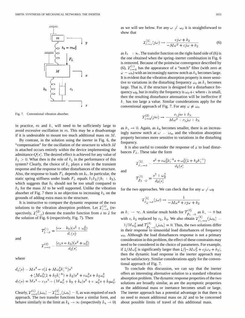
Fig. 7. Conventional vibration absorber.
in practice, and will need to be sufficiently large toavoid excessive oscillation in . This may be a disadvantageif it is undesirable to mount too much additional mass on.
By contrast, in the solution using the inerter in Fig. 6, the“compensation” for the oscillation of the structure to whichis attached occurs entirely within the device implementing theadmittance . The desired effect is achieved for any value of
. What then is the role of in the performance of thissystem? Clearly, the choice of plays a role in the transientresponse and the response to other disturbances of the structure.Also, the response to loads depends on . In particular, thestatic spring stiffness under loads equals ,which suggests that should not be too small compared to
for the mass to be well supported. Unlike the vibrationabsorber of Fig. 7 there is no objection to increasingon thegrounds of adding extra mass to the structure.
It is instructive to compare the dynamic response of the twosolutions to the vibration absorption problem. Let (re-spectively, ) denote the transfer function fromto forthe solution of Fig. 6 (respectively, Fig. 7). Then
and
where
Clearly, , as was required of eachapproach. The two transfer functions have a similar form, andbehave similarly in the limit as (respectively )
as we will see below. For any it is straightforward toshow that
(6)
as . The transfer function on the right-hand side of (6) isthe one obtained when the spring–inerter combination in Fig. 6is removed. Because of the pointwise convergence described by(6), has the appearance of a “notch” filter (with zero at
) with an increasingly narrow notch asbecomes large.It is evident that the vibration absorption property is more sensi-tive to variations in the disturbing frequency as becomeslarge. That is, if the structure is designed for a disturbance fre-quency , but in reality the frequency is where is small,then the resulting disturbance attenuation will be ineffective if
has too large a value. Similar considerations apply for theconventional approach of Fig. 7. For any
as . Again, as becomes smaller, there is an increas-ingly narrow notch at , and the vibration absorptionproperty becomes more sensitive to variations in the disturbingfrequency.
It is also useful to consider the response ofto load distur-bances . These take the form
and
for the two approaches. We can check that for any
as . A similar result holds for as but
with , replaced by , . We also obtain
and . Thus, the two solutions differin their response to sinusoidal load disturbances of frequency
. Although the load disturbances response is not a primaryconsideration in this problem, the effect of these constraints mayneed to be considered in the choice of parameters. For example,if is significantly larger than ,then the dynamic load response in the inerter approach maynot be satisfactory. Similar considerations apply for the conven-tional approach of Fig. 7.
To conclude this discussion, we can say that the inerteroffers an interesting alternative solution to a standard vibrationabsorption problem. The dynamic response properties of the twosolutions are broadly similar, as are the asymptotic propertiesas the additional mass or inertance becomes small or large.The inerter approach has a potential advantage in that there isno need to mount additional mass on and to be concernedabout possible limits of travel of this additional mass.

1654 IEEE TRANSACTIONS ON AUTOMATIC CONTROL, VOL. 47, NO. 10, OCTOBER 2002
Fig. 8. Frequency responsesT : inerter (–), conventional (–�).
D. Numerical Example
Consider the problem as posed in Fig. 5 with kg andHz. Suppose it is required that a constant load
N produces a deflection atof at most 1 mm, so that the staticspring stiffness is at least 10Nm . If is chosen to be aspring in parallel with a damper, then in Fig. 5
where , . Setting Nmgives when and
as . Thus, even in the limit as the damping ratiovanishes (which is likely to be unacceptably oscillatory in anycase), the maximal reduction in amplitude is to 34% of the dis-turbance amplitude. For critical damping the reduction is onlyto 83%. Evidently, the ordinary spring–damper arrangement isunlikely to provide an acceptable solution for this problem.
Let us begin with the conventional approach of Fig. 7. Asbecomes smaller, the “notch” in the frequency response be-
comes increasingly narrow. Also, we can observe an oscillatorycomponent in the time response which is hard to dampen byadjusting . There is clearly a practical limit to how largecan be. Let us choose the parameters kg,
Nm , Nm andNsm . The resulting frequency response is shown
in Fig. 8 and the step response of is shown in Fig. 9. The
steady-state amplitude of equalstimes the amplitude of the sinusoidal disturbance at.
Turning to the approach of Fig. 6 using the inerter. To achievea static stiffness of Nm we need to choose
. At either extreme for (close to or tendingtoward infinity), we can again observe an oscillatory componentin the time response which is hard to dampen by adjusting. Thefollowing parameter choices give a reasonably wide notch andmoderate overall damping: Nm ,
Nm , Nsm . This requires aninerter of inertance 22.80 kg. The resulting frequency response
is shown in Fig. 8 and the step response of isshown in Fig. 9.
Fig. 9. Response ofx to a unit step atF : inerter (–), conventional (–�).
Fig. 10. Quarter-car vehicle model.
IV. V EHICLE SUSPENSIONS
A. Quarter-Car Model
An elementary model to consider the theory of active and pas-sive suspensions is the quarter-car of Fig. 10 (see, e.g., [25] and[14]) consisting of the sprung mass , the unsprung massand a tyre with spring stiffness . The suspension strutpro-vides an equal and opposite force on the sprung and unsprungmasses and is assumed here to be a passive mechanical admit-tance which has negligible mass. The equations of motionin the Laplace transformed domain are
(7)
(8)
Using the force–current analogy, the quarter-car model hasan electrical analog as shown in Fig. 11, with the two massesbecoming grounded capacitors and the two external inputs(loads on the sprung mass) and(road undulations modeledas a velocity source) becoming current and voltage sources,respectively.

SMITH: SYNTHESIS OF MECHANICAL NETWORKS: THE INERTER 1655
Fig. 11. Equivalent electrical circuit for quarter-car model.
B. Suspension Struts
A fully active suspension allows a much greater designfreedom than the traditional suspension struts [27], [29], butthere are drawbacks in terms of expense and complexity.Currently, passive suspension struts make use only of springsand dampers. In electrical terms this corresponds to circuitscomprising inductors and resistors only. The driving-pointimpedance or admittance of such circuits is quite limitedcompared to those using capacitors as well, as is shown by thefollowing result which is translated directly from its electricalequivalent [11, pp. 58–64].
Theorem 3: Consider any one-port mechanical networkwhich consists of a finite interconnection of springs anddampers. If its driving-point admittance exists then it is a(real-rational) positive real function with the followingproperties: all its poles and zeros are simple and alternate onthe negative real axis with a pole, possibly at the origin, beingthe rightmost of these.
For convenience we call a function satisfying the conditionsof Theorem 3 aspring-damper (SD) admittance(in electricalnetworks the term RL admittance is used). Any SD admittance
must satisfy the following two conditions:
(9)
dB Bode-slope dB (10)
for . This follows by considering the contribution of eachpole and zero in turn, which gives:
where .A similar argument proves (10). These conditions on an SDadmittance do not apply to a general positive-real admittance,which may exhibit phase lead and has no fundamental restric-tions on the local Bode-slope. It seems clear that there couldbe significant advantages in optimizing the performance of pas-sive suspension systems over the class of positive-real functions.The use of inerters as well as springs and dampers provides themeans to do this.
C. Low Degree Positive Real Admittances
It is a general result of network synthesis [11, pp. 127–130]that any SD admittance can be realized as in Fig. 12,where is the number of zeros of . Even if transformers(levers) are allowed in addition to springs and dampers the class
of achievable admittances is still the same as that given by The-orem 3 (see [28]). Thus, the most general SD admittance with(positive-static stiffness) using springs and one damper is givenby
(11)
where and , while the most general formwith two dampers is
(12)
where and . To investigate thepossible benefits that inerters might provide let us consider theclass ofarbitrary positive real mechanical admittances of thesame order as .
Theorem 4: Consider the real-rational function
(13)
where , and . Then, is positive real if onlyif the following three inequalities hold:
(14)
(15)
(16)
Furthermore, is an SD admittance of McMillan degreethree if and only if , , and the followinginequality holds:
(17)
(These last four inequalities together imply and ).Proof: Assume is positive real. We can calculate that
(18)
By considering the behavior near and , we con-clude that (14) and (16) must hold. Now, if , then
which means that (15) must hold. If then (15) mustagain hold since implies has zeros with positivereal part which contradicts the positive realness assumption. Solet us consider the remaining case where and .In this case, a pole occurs on the imaginary axis at .From (14), it follows that , whence the residue at the poleis equal to . Since this must be nonnegative thisagain establishes (15), completing all cases.
For the converse direction, from (18) so weneed only check the residue conditions for any imaginary axispoles. The pole at has residue . A pole atcan occur if in which case the residue is .If and then a pole occurs on the imaginary axisat . Again, from (14) and the residue at thepole is equal to which is nonnegative. Thisproves positive realness of .

1656 IEEE TRANSACTIONS ON AUTOMATIC CONTROL, VOL. 47, NO. 10, OCTOBER 2002
Fig. 12. Realization of a general SD admittance.
Turning to the final claim, is an SD admittance ofMcMillan degree 3 if and only if is positive real andsatisfies the pole-zero interlacing property of Theorem 3(with strict inequalities). Using [10, Ch. XV, Th. 11] theinterlacing property holds (with strict inequalities) if and onlyif is Hurwitz. Using theLiénard–Chipart criterion [10, Ch. XV, Th. 13] the latter holdsif the only if the following inequalities hold: ,
(19)
We can check that the two determinants in (19) are equal toand . It can also be seen that (17) implies , whence
follows from .Before studying the possible benefits of the admittance (13),
let us consider how it could be realized.
D. Realizations Using Brune Synthesis
The synthesis ofgeneralpositive-real functions cannot beachieved with such a simple canonical form as Fig. 12 and re-quires the more sophisticated procedures of Section II-D. Forthe realization of the admittance (13) we can assume withoutloss of generality that
A1) ;A2) .
We can justify this as follows. If , then eitheror [by combining (14) and (16)], which in both
cases leads to a loss of McMillan degree and the possibility ofrealization in the form of Fig. 12. If , then (17) implies
, and (14) then implies . This is sufficientfor the pole-zero interlacing property of Theorem 3 to hold (thecase of can be checked as in the proof of Theorem 4) sothat realization in the form of Fig. 12 is again possible. Now, if
and (which implies that ) then we cancheck that is a common pole-zero pair in (13) so againrealization is possible in the form of Fig. 12.
The first step in the Brune procedure [4, Ch. 9.4] is to removethe imaginary axis poles and zeros. We write
(20)
and then
(21)
(22)
(23)
The decomposition in (22) is obtained by subtracting off theminimum of the real part of the second term in (21), and thesame procedure is used on the inverse of that term to give (23).Equations (22) and (23) together with (20) give the realizationsshown in Figs. 13 and 14 with the following expressions for theconstants: :
(24)
(25)
We can observe that
Since we see that , and ,so the realization of Fig. 14 is the more efficient one in the senseof having smaller parameter values.
It is useful to point out that the Brune procedure was relativelysimple for the admittance (13), since the minimum real part oc-curred at zero or infinite frequency where the imaginary part waszero. Thus, the use of a “Brune cycle” involving transformers,or the alternative Bott–Duffin procedure, was not required.
E. A Strut Design Example
To illustrate the potential application of the inerter weconsider the simple idealized problem of designing a sus-pension strut which has high static stiffness to applied loads
but which has well-damped time responses. We choosethe following parameters: kg, kg,
kNm and require that the strut behaves staticallylike a spring of stiffness kNm [27], [29]. Weconsider the set of system poles of the quarter-car model of (7),(8), which is equal to the set of zeros of
(26)
We consider the least damping ratio among all the systempoles for a given . We seek to maximize as a func-tion of the admittance for various choices of admittanceclasses.
1) Design 1: SD Admittance With One Damper:We con-sider the case of as in (11) with . Theoptimization of over and appears to be convex (seeFig. 15) with a maximum at , and

SMITH: SYNTHESIS OF MECHANICAL NETWORKS: THE INERTER 1657
Fig. 13. First realization of the admittance (13).
Fig. 14. Second realization of the admittance (13).
. This corresponds to the simplest suspension strutof a spring in parallel with a damper with admittance
where the damper constant is given by kNsm .Fig. 16 shows the step response fromto with rather lightdamping in evidence. This highlights one of the difficulties withconventional suspension struts which are very stiffly sprung.
2) Design 2: SD Admittance With Multiple Dampers:Forthe same optimization problem, but with as in(12) and , direct searches using the Nelder–Mead sim-plex method led to no improvement on the value of
obtained in Design 1 with one damper. This situation ap-pears to persist for a higher number of dampers as in Fig. 12.Further direct searches in the parameter space converged to-ward a set of pole-zero cancellations, and consequent reductionin McMillan degree in , leaving only the solution obtainedin Design 1. These claims are backed only by computationalevidence, with a formal proof being lacking.
Fig. 15. Plot of damping ratio� versusT andT in Design 1.
Fig. 16. Response ofz to a unit step atz : Design 1 (–) and Design 3 (–�).
3) Design 3: Degree 3 Positive-Real Admittance:For thesame optimization problem, but with the admittance
as in equation (13), and no SD restriction, directsearches using the Nelder–Mead simplex method led to clearimprovements. The following parameters
(27)
gave a value of . The improved damping is demon-strated in Fig. 16 compared to the case of Design 1. The posi-tive-real nature of is illustrated in the Bode plot of Fig. 17,which also clearly shows that this solution is employing phaseadvance. The latter fact proves that is not an SD admit-tance, as is also seen by . The valuesfor the constants in the realizations of Figs. 13 and 14 are givenby
kNsm kNsm
kg kNsm
kNsm kg
These values appear to be within the bounds of practicality.

1658 IEEE TRANSACTIONS ON AUTOMATIC CONTROL, VOL. 47, NO. 10, OCTOBER 2002
Fig. 17. Bode plot for the admittanceY (s) of Design 3.
Fig. 18 shows the response of the sprung mass, suspensionworking space, tire deflection, and relative displacement of thedamper (in the realization of Fig. 14) to a unit step road dis-turbance. Note that the inerter linear travel has a similar overallmagnitude to the strut deflection due to the fact that the damper
is quite stiff and has small travel.
F. Realizations Using Darlington Synthesis
The realizations shown in Figs. 13 and 14 both require theuse of two dampers. It is interesting to ask if the admittance (13)may be realized using only one damper. An approach which willachieve this uses the method of Darlington [5], [11, Ch. IX.6]. Inthe electrical context the method allows any positive-real func-tion to be realized as the driving-point impedance of a losslesstwo-port network terminated in a single resistance as shown inFig. 19. Since there is noa priori estimate on the minimumnumber of inductors, capacitors (and indeed transformers) re-quired for the realization of the lossless network, we will need tocarry out the procedure to determine if the saving of one damperis offset by other increases of complexity, e.g., the need for morethan one inerter or the use of levers.
For a reciprocal two-port network with impedance matrix
we can check that in Fig. 19
(28)
Writing
where , are polynomials of even powers ofand ,are polynomials of odd powers of, suggests the identification
(29)
Fig. 18. Responses of Design 3 to a step input atz : z (–), z � z (–�),z � z (�), and deflection of damperc (– –).
Fig. 19. Realization of a positive real impedance in Darlington form.
This corresponds to Case B in [11, Ch. IX.6]. Definingin (13) gives , ,
, and , from which
(30)
We now make the following two assumptions:
A1) ;A2) .
The first of these involves no loss of generality sinceimplies , which means that (13) is an SD admittancerequiring only one damper for its realization. The second avoidsvarious special cases which can be dealt with in a rather simplerway than the general development which now follows.
Since (30) is not a perfect square it is necessary to multiplynumerator and denominator in by the polynomial
(determined by ).This gives where
and . Then, using the corre-spondences in (29) with replaced by , etc., we obtain thefollowing expression for the impedance of the lossless two-port:

SMITH: SYNTHESIS OF MECHANICAL NETWORKS: THE INERTER 1659
We now write
(31)
where the constant matrices and are given by
Following [11, Ch. VII.1] we note that any impedance matrixof the form , where is scalar and
is nonnegative definite, can be realized in the form of the T-cir-cuit of Fig. 20 with = and
In order for , it is necessary and sufficient thatand
We can now apply this realization procedure to each term in(31) and obtain the sum by taking a series connection of the tworesulting two-ports (see Fig. 21).
We begin with and observe that , which fixesthe choice of and ensures that . Since bothand then vanish from the T-circuit, this has the consider-able advantage that only a single oscillator (inductor–capacitoror spring–inerter parallel connection) will be required, which isa significant economy. Moreover, we may dispense with a trans-former by a choice of which gives :
(32)
We now set the first element of the second term in (31) equal to aparallel capacitor–inductor combination with impedance
to obtain the parameters
(33)
(34)
We denote the capacitance byand the inductance by inanticipation of the mechanical analogy.
Turning to , we note that a transformer will be requiredhere with and the range of transformer ratios given by
(35)
Fig. 20. T-circuit realization of elementary lossless two-ports.
Fig. 21. Series connection of a pair of two-port networks.
Choosing at the lower (respectively, upper) limit sets (re-spectively, ) to be zero. It will be convenient to always selectthe lower limit. After suitable manipulation we can find expres-sions for the inductances and (whoseinverses will be spring constants in the mechanical analogy)
(36)
(37)
We can now take the series connection of the two terms in (31)plus the terminating resistor to yield the circuit diagram shownin Fig. 22. A technical condition for the series connection inFig. 21 to be valid is that no circulatory current can exist, whichis satisfied in this case because of the presence of a transformer(see [11, Ch. VI.1], [13, pp. 325–326]).
It remains to deduce the mechanical analog of Fig. 22. Theideal transformer can be implemented as a simple lever withpivot point at the common node of the spring–inerter parallelcombination. The central pivot automatically corresponds to anideal transformer with negative turns ratio, which is what werequire. Therefore, we obtain the mechanical realization of theadmittance (13) with, , , and given by (33), (34), (36),and (37)
and (38)
It is possible to directly calculate the admittance of the me-chanical one-port networks in Fig. 23 as a function of the pa-rameters , , , , , , to be given by (39) at the bottom ofthe next page. Clearly, the McMillan degree of (39) is one higher

1660 IEEE TRANSACTIONS ON AUTOMATIC CONTROL, VOL. 47, NO. 10, OCTOBER 2002
Fig. 22. Electrical circuit realization of the admittance (13).
than the admittance we started with in (13). Since there are fourenergy storage elements in Fig. 23 (three springs and one in-erter), the extra degree is not unexpected from general circuittheory considerations. How then is equality with (13) to be ex-plained? The answer is that there is an interdependence in theparameter values of , , , , , , as defined through (33),(34), and (36)–(38) which is sufficient to ensure a pole-zerocancellation in (39). In the case when , which makes
, this interdependence is expressed by
(The general relationship is significantly more complicated). Itis evident that the mechanical network in Fig. 23 parameterizesa class of admittances which is strictly larger than those in (13)if the parameter values of , , , , , and are allowed tovary independently.
It is interesting to make any possible comparisons betweenparameter values required in Fig. 23 and those for the realizationin Fig. 14 for the admittance (13). In fact, it is possible to show
(40)
(41)
(42)
(43)
To show (40), we note that while
For (41), note that and ;(42) follows from:
Fig. 23. Third realization of the admittance (13).
and (43) follows from:
It appears difficult to give any usefula priori estimates for thelever ratio .
We now return to the suspension strut design of Sec-tion IV-E-3. For the parameter values given in (27), therealization of Fig. 23 gives the following values for the con-stants using equations (33), (34), and (36)–(38)
kg kNm
kNm kNsm
These values appear to be within the bounds of practicality.After carrying out the Darlington procedure for the real-
ization of the admittance (13), we note that the saving of onedamper from the realizations of Figs. 13 and 14 has been offsetby the need for a lever. The extra spring and increased valueof inerter constant implied in (40) are perhaps less significantdifferences.
V. SIMULATED MASS
The previous two applications of the inerter exploited oneof its principal advantages over the mass element, namely thatneither of its terminals need to be grounded. There is also thepossibility that the inerter could be used to replace a mass
(39)

SMITH: SYNTHESIS OF MECHANICAL NETWORKS: THE INERTER 1661
element with one of its terminals then being connected toground. This is illustrated in Fig. 24(a) and (b), which are inprinciple equivalent dynamically with respect to displacementdisturbances .
Fig. 24(b) may be a useful alternative to Fig. 24(a) in a sit-uation where it is desired to test a spring–damper support orabsorber before final installation, and where it is impractical totest it on a real mass element, e.g., where the massis verylarge.
By contrast, it should be pointed out that, even in the contextof mechanical network synthesis, Fig. 24(b) may not be a phys-ically feasible alternative to Fig. 24(a) in situations where it isimpossible to connect one terminal of the inerter to ground, e.g.,for a vibration absorber mounted on a bridge.
VI. CONCLUSION
This paper has introduced the concept of the ideal inerter,which is a two-terminal mechanical element with the definingproperty that the relative acceleration between the two terminalsis proportional to the force applied on the terminals. There is norestriction that either terminal be grounded, i.e., connected to afixed point in an inertial frame. The element may be assumed tohave small or negligible mass. The ideal inerter plays the roleof the true network dual of the (ideal) mechanical spring.
It was shown that the inerter is capable of simple realization.One approach is to take a plunger sliding in a cylinder driving aflywheel through a rack, pinion and gears. Such a realization sat-isfies the property that no part of the device need be attached toground, and that it has a finite linear travel which is specifiable.The mass of the device may be kept small relative to the iner-tance (constant of proportionality) by employing a sufficientlylarge gear ratio. Such a realization may be viewed as approxi-mating its mathematical ideal in the same way that real springs,dampers, capacitors, etc. approximate their mathematical ideals.
The inerter completes the triple of basic mechanical networkelements in a way that is advantageous for network synthesis.The properties that neither terminal need be grounded and thedevice mass may be small compared to the inertance are crucialfor this purpose. It allows classical electrical circuit synthesis tobe exploited directly to synthesize any one-port (real-rational)positive-real impedance as a finite network comprising springs,dampers, and inerters. The use of the inerter for synthesis doesnot prevent mechanical networks containing mass elementsfrom beinganalyzedin the usual way as the analogs of groundedcapacitors. Moreover, as well as the possibility that in somesituations it is advantageous that one terminal of the masselement is the ground, there is also the possibility that theinerter may have benefits tosimulate a mass element withone of its terminals being connected to ground.
A vibration absorption problem was considered as a pos-sible application of the inerter. Rather than mounting a tunedspring–mass system on the machine that is to be protectedfrom oscillation (conventional approach), a black-box me-chanical admittance was designed to support the machinewith a blocking zero on the imaginary axis at the appropriatefrequency. The resulting mechanical network consisted of aparallel spring-damper in series with a parallel spring inerter.
(a)
(b)
Fig. 24. Spring–damper supporting (a) a mass element and (b) a groundedinerter acting as a simulated mass.
This arrangement avoids any associated problems of attachingthe spring-mass to the machine, such as the need for anundesirably large mass to limit its travel.
A vehicle suspension strut design problem was considered asanother possible application of the inerter. It was pointed out thatconventional struts comprising only springs and dampers haveseverely restricted admittance functions, namely their polesand zeros all lie on the negativ real axis and the poles and zerosalternate, so that the admittance function always has a laggingfrequency response. The problem of designing a suspensionstrut with very high static spring stiffness was considered. Itwas seen that conventional spring and damper arrangementsalways resulted in very oscillatory behavior, but the use ofinerters can reduce the oscillation. In studying this problem, ageneral positive real admittance was considered consisting oftwo zeros and three poles. The realization procedure of Brunewas applied to give two circuit realizations of the admittance,each of which consisted of two springs, two dampers and oneinerter. The resulting parameter values for the strut designappear within the bounds of practicality. As an alternative,the realization procedure of Darlington was used to finding arealization consisting of one damper, one inerter, three springsand a lever.

1662 IEEE TRANSACTIONS ON AUTOMATIC CONTROL, VOL. 47, NO. 10, OCTOBER 2002
ACKNOWLEDGMENT
The author would like to thank G. W. Walker for many stim-ulating conversations on vehicle suspensions and mechanicalnetworks. It was within the context of these conversations thatthe question was asked on the possible existence of a physicaldevice of the type defined here, which was later found to berealizable, and coined “the inerter.”
REFERENCES
[1] B. D. O. Anderson and S. Vongpanitlerd,Network Analysis and Syn-thesis. Upper Saddle River, NJ: Prentice-Hall, 1973.
[2] V. Belevitch, Classical Network Theory. San Francisco, CA:Holden-Day, 1968.
[3] R. Bott and R. J. Duffin, “Impedance synthesis without use of trans-formers,”J. Appl. Phys., vol. 20, p. 816, 1949.
[4] O. Brune, “Synthesis of a finite two-terminal network whose driving-point impedance is a prescribed function of frequency,”J. Math. Phys.,vol. 10, pp. 191–236, 1931.
[5] S. Darlington, “Synthesis of reactance 4-poles which produce pre-scribed insertion loss characteristics,”J. Math. Phys., vol. 10, pp.257–353, 1931.
[6] , “A history of network synthesis and filter theory for circuitscomposed of resistors, inductors, and capacitors,”IEEE Trans. CircuitsSyst.I, vol. 46, pp. 4–13, Jan. 1999.
[7] M. Darrieus, “Les modèles mécaniques en électrotechnique leur appli-cation aux problèmes de stabilité,”Bull. Soc. Fra. Elect., vol. 96, pp.794–809, 1929.
[8] J. P. Den Hartog,Mechanical Vibrations. New York: Dover, 1985.[9] F. A. Firestone, “A new analogy between mechanical and electrical sys-
tems,”J. Acoust. Soc. Amer., vol. 4, pp. 249–267, 1933.[10] F. R. Gantmacher,The Theory of Matrices. New York: Chelsea, 1980,
vol. II.[11] E. A. Guillemin, Synthesis of Passive Networks. New York: Wiley,
1957.[12] W. Hähnle, “Die Darstellung elektromechanischer Gebilde durch rein
elektrische Schaltbilder,”Wiss. Veröff. Siemens-Konz., vol. 11, pp. 1–23,1932.
[13] W. W. Harman and D. W. Lytle,Electrical and Mechanical Networks:McGraw-Hill, 1962.
[14] J. K. Hedrick and T. Butsuen, “Invariant properties of automotive sus-pensions,”Proc. Inst. Mech. Eng D: J. Automobile Eng., vol. 204, pp.21–27, 1990.
[15] E. L. Hixson, “Mechanical impedance,” inShock and Vibration Hand-book, 2nd ed, C. M. Harris and C. E. Crede, Eds. New York: Mc-Graw-Hill, 1976, ch. 10.
[16] D. C. Karnopp and R. C. Rosenberg,Analysis and Simulation ofMultiport Systems: The Bond Graph Approach to Physical SystemDynamics. Cambridge, MA: MIT Press, 1968.
[17] D. C. Karnopp, D. L. Margolis, and R. C. Rosenberg,System Dynamics:Modeling and Simulation of Mechatronic Systems. New York: Wiley,2000.
[18] W. J. Karplus and W. W. Soroka,Analog Methods. New York: Mc-Graw-Hill, 1959.
[19] H. E. Koenig and W. A. Blackwell,Electromechanical SystemTheory. New York: McGraw-Hill, 1961.
[20] A. G. J. MacFarlane,Dynamical System Models. Edinburgh, U.K.:Chambers Harrap, 1970.
[21] R. W. Newcomb,Linear Multiport Synthesis. New York: McGraw-Hill, 1966.
[22] H. F. Olson,Dynamical Analogies. New York: Van Nostrand, 1943.[23] H. M. Paynter, Analysis and Design of Engineering Sys-
tems. Cambridge, MA: MIT Press, 1961.[24] J. C. Schönfeld, “Analogy of hydraulic, mechanical, acoustic and elec-
trical systems,”Appl. Sci. Res., B, vol. 3, pp. 417–450, 1954.[25] R. S. Sharp and S. A. Hassan, “The relative performance capabilities of
passive, active and semi-active car suspension systems,” inProc. Inst.Mech. Engs., vol. 200, 1986, pp. 219–228.
[26] J. L. Shearer, A. T. Murphy, and H. H. Richardson,Introduction toSystem Dynamics. Reading, MA: Addison-Wesley, 1967.
[27] M. C. Smith, “Achievable dynamic response for automotive active sus-pension,”Veh. Syst. Dyna., vol. 24, pp. 1–33, 1995.
[28] M. C. Smith and G. W. Walker, “A mechanical network approach toperformance capabilities of passive suspensions,” inProceedings of theWorkshop on Modeling and Control of Mechanical Systems. London,U.K.: Imperial College Press, June 17–20, 1997, pp. 103–117.
[29] M. C. Smith and G. W. Walker, “Performance limitations and constraintsfor active and passive suspensions: A mechanical multi-port approach,”Veh. Syst. Dyna., vol. 33, pp. 137–168, 2000.
[30] H. M. Trent, “Isomorphisms between oriented linear graphs and lumpedphysical systems,”J. Acoust. Soc. Amer., vol. 27, pp. 500–527, 1955.
[31] P. E. Wellstead,Introduction to Physical System Modeling. New York:Academic, 1979.
Malcolm Smith (M’90–SM’00–F’02) received theB.A. degree in mathematics, the M.Phil. degree incontrol engineering and operational research, and thePh.D. degree in control engineering from the Univer-sity of Cambridge, Cambridge, U.K., in 1978, 1979,and 1982, respectively.
He was subsequently a Research Fellow at theGerman Aerospace Center, DLR, Oberpfaffenhofen,Germany, a Visiting Assistant Professor and Re-search Fellow with the Department of ElectricalEngineering at McGill University, Montreal, Canada,
and an Assistant Professor with the Department of Electrical Engineering atthe Ohio State University, Columbus, OH. In 1990, he returned to CambridgeUniversity as a Lecturer in the Department of Engineering, and became aReader in 1997. He is a Fellow of Gonville and Caius College, Cambridge,U.K. His research interests include control system design, frequency responsemethods, H-infinity optimization, nonlinear systems, active suspension, andmechanical systems.
Dr. Smith was a corecipient of the George Axelby Outstanding Paper Awardin the IEEE TRANSACTIONS ONAUTOMATIC CONTROL in 1992 and 1999, bothtimes for joint work with T. T. Georgiou.