synthesis and mechanical reconfiguration of ground plane
TRANSCRIPT
Journal of Microwaves, Optoelectronics and Electromagnetic Applications, Vol. 19, No. 2, June 2020
DOI: http://dx.doi.org/10.1590/2179-10742020v19i2838 228
Brazilian Microwave and Optoelectronics Society-SBMO received 26 Sept 2019; for review 10 Oct 2019; accepted 9 Apr 2020
Brazilian Society of Electromagnetism-SBMag © 2020 SBMO/SBMag ISSN 2179-1074
Abstract— A synthesis procedure of a mechanically reconfigurable
antenna based on tetra-circle fractal patch elements is presented,
enabling to change both resonant frequencies and radiation pattern
performance. The antenna geometry reconfiguration is implemented
by tilting the ground plane of the microstrip antenna with respect to
the fractal patch and substrate layer. The tilt angle is defined as the
angle between the back of the dielectric substrate and the tilted
ground plane and is electromechanically varied using a thin rod of
dielectric material sliding up and down, in a simple geometry.
Simulation results for the proposed antenna parameters are
obtained using Ansoft HFSS software. In addition to promoting
frequency and pattern reconfiguration, the tilting of the ground
plane has proven to be an alternative to increase the antenna gain
and enable single-band or dual-band operation. Prototypes were
fabricated and measured for comparison purpose showing a good
agreement between simulation and measurement results.
Index Terms— Reconfigurable antenna, mechanically reconfiguration, fractal
patch, tetra-circle fractal.
I. INTRODUCTION
The modern wireless communication systems have required the development of compact devices,
such as printed circuits [1], [2], including microstrip antennas, to perform a large number of service
applications with high transmission and reception rates. Typically, a microstrip antenna is composed of
a metallic patch printed on a dielectric substrate which is mounted on a ground plane. The shape and
dimensions of the metallic patch play an important role on the microstrip antenna performance. Metallic
patches with different shapes have been used, including rectangles, triangles, circles, regular polygons,
fractals and quasi-fractals.
Over the years, with the advancement of telecommunication systems, many researchers have been
working on the development of microwave circuits capable of operating in different frequency bands
and whose parameters can be easily changed or reconfigurated [3]-[6]. In [3], the use of reconfigurable
antennas is performed to make one antenna works for different systems and applications.
In [4], a reconfiguration based on the use of a liquid actuator as an antenna substrate was proposed.
A liquid polymer is placed below the resonator patch and an aluminum structure is placed around the
Synthesis and Mechanical Reconfiguration of
Ground Plane Tilted Microstrip Antennas
Based on Tetra-Circle Fractals Mychael Jales Duarte , Valdemir P. da Silva Neto and Adaildo Gomes D’Assunção
Federal University of Rio Grande do Norte, UFRN-CT-DCO, Caixa Postal 1655,
Natal, RN, Brazil, 59078-970
Journal of Microwaves, Optoelectronics and Electromagnetic Applications, Vol. 19, No. 2, June 2020
DOI: http://dx.doi.org/10.1590/2179-10742020v19i2838 229
Brazilian Microwave and Optoelectronics Society-SBMO received 26 Sept 2019; for review 10 Oct 2019; accepted 9 Apr 2020
Brazilian Society of Electromagnetism-SBMag © 2020 SBMO/SBMag ISSN 2179-1074
patch. When an electrostatic force is applied on the aluminum structure, it goes down, pushing the
polymer further towards the center, and consequently, raising the patch. This works as an increase of
the substrate thickness and modifies the antenna resonant frequency value.
In [5], a rectangular ring patch antenna is presented, which enables a polarization reconfiguration and
small deviation on the resonant frequency. The antenna has two feeders which are composed of coupling
patches, an impedance transformer and a variable capacitor. The antenna reconfiguration is provided
by the variation of the capacitance value.
A polarization reconfiguration through PIN diodes placed near the antenna's edge, where these diodes
make the connections for small patches is proposed in [6]. Depending on whether the diodes are ON
(polarized) or OFF (non-polarized), the polarization of the antenna is circular or not, with very small
variation on the resonant frequency.
This work proposes a new mechanically reconfigurable patch antenna for wireless communications
systems. The patch antenna is based on a fractal shape. Depending on the reconfiguration status, the
antenna can operate on different wireless communication systems, such as Bluetooth and Wi-Fi (2.40
GHz at 2.483 GHz), multimedia communication (SCM), personal mobile (SMP) systems (3.4 GHz to
3.6 GHz), earth exploration satellite systems, space research, radiolocation or aeronautical
radionavigation (5.35 GHz to 5.46 GHz).
Results for the reflection coefficient as function of frequency, bandwidth, resonant frequency and
VSWR were simulated using Ansoft HFSS. A prototype was fabricated and measured for comparison
purpose. Good agreement between simulation and measurement results was verified.
II. ANTENNA SYNTHESIS
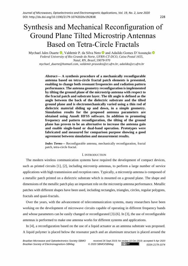
The antenna geometry is based on the tetra-circle fractal. This fractal is based on a larger central
circle and other four circles which radii are half of the central circle radius. These four circles are
centered equidistantly at the end of the larger circle, divided into four congruent arcs, as shown in Fig. 1.
(a) (b) (c) (d)
Fig. 1. Tetra-circle fractal geometries with different iteration levels. (a) N = 0, (b) N = 1, (c) N = 2, and (d) N = 3.
The proposed microstrip antenna patch geometry based on tetra-circle fractal of iteration level N = 2
is shown in Fig. 2. The patch central circle radius is ra and the small circles radius are ra/4. The

Journal of Microwaves, Optoelectronics and Electromagnetic Applications, Vol. 19, No. 2, June 2020
DOI: http://dx.doi.org/10.1590/2179-10742020v19i2838 230
Brazilian Microwave and Optoelectronics Society-SBMO received 26 Sept 2019; for review 10 Oct 2019; accepted 9 Apr 2020
Brazilian Society of Electromagnetism-SBMag © 2020 SBMO/SBMag ISSN 2179-1074
microstrip dimensions are width, WL, and length, LL, and the dielectric substrate parameters are relative
permittivity, εr, and substrate height, h. A tri-circle geometry was used to reduce the patch antenna size
and use a microstrip line feed.
Fig. 2. Proposed microstrip antenna patch geometry based on the tetra-circle fractal of iteration level 2.
In this work, the synthesis of a tetra-circle fractal resonator is based on the statistical technique of the
response surface methodology (RSM method). This technique is widely used in the modeling and
analysis of problems in which the response depends on many variables [7].
The RSM method consists of finding an approximate equation to relate the desired response and the
factors that interfere with it. This equation must lead to an optimal value (maximum, minimum or target)
of the response [8]. The first step in this methodology is to find out an adequate approximation for the
relationship between the independent variables and the dependent variable. Normally, a low order
polynomial [8] is used.
Assuming the expected response y as a function of k independent variables x1, x2, …, xk, the
relationship between y and the independent variables can be described as first-order, second-order or
higher order polynomials [7], [8], as shown below.
𝑦 = 𝛽0 + ∑ 𝛽𝑖𝑥𝑖𝑘𝑖=1 +∈(1)
𝑦 = 𝛽0 + ∑ 𝛽𝑖𝑥𝑖𝑘𝑖=1 + ∑ 𝛽𝑖𝑖𝑥𝑖
2𝑘𝑖=1 + ∑ ∑ 𝛽𝑖𝑗𝑥𝑖𝑥𝑗𝑖<𝑗 +∈(2)
In (1) and (2), for the calculation of the β values, the least squares method is used. The
response surface methodology was used to relate the structural parameters of a microstrip
antenna with its resonant frequency, fr, to obtain a synthesis approximate expression. The
antenna structural parameters are: radius of the larger patch, ra, substrate height, h, and relative
Journal of Microwaves, Optoelectronics and Electromagnetic Applications, Vol. 19, No. 2, June 2020
DOI: http://dx.doi.org/10.1590/2179-10742020v19i2838 231
Brazilian Microwave and Optoelectronics Society-SBMO received 26 Sept 2019; for review 10 Oct 2019; accepted 9 Apr 2020
Brazilian Society of Electromagnetism-SBMag © 2020 SBMO/SBMag ISSN 2179-1074
permittivity, εr. The data for this statistical modelling were obtained using Ansoft HFSS
simulations in a three steps parametric analysis.
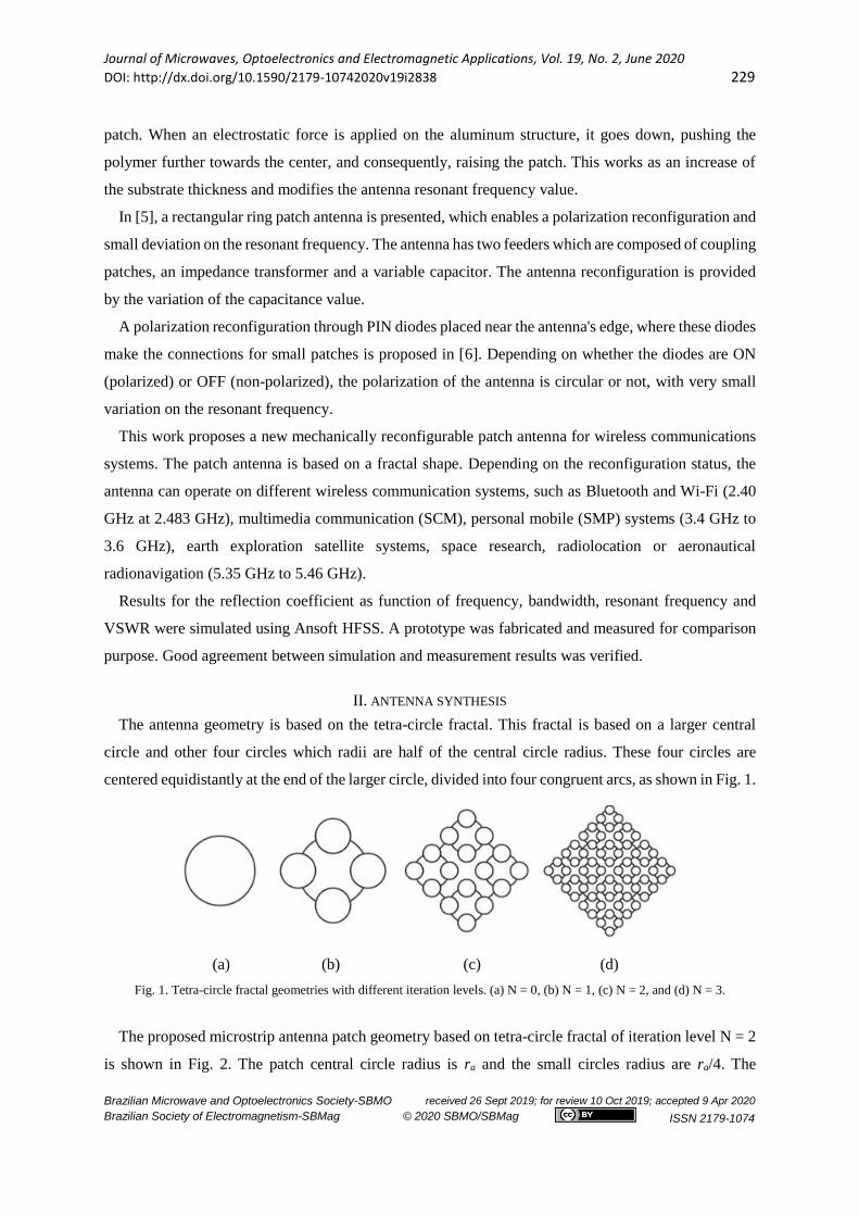
In the first step, the relative permittivity is 4.4, the substrate height is 1.57 mm, and the patch radius,
ra, is varied from 8 to 18 (mm). The effect on the antenna resonant frequency, fr, is shown in Fig. 3 and
is inversely proportional to the antenna larger patch radius, ra.
Fig. 3. Resonant frequency as function of the antenna higher patch radius, ra.
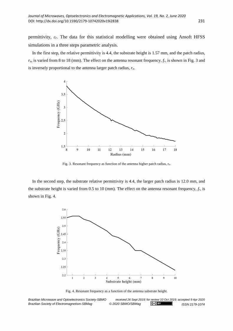
In the second step, the substrate relative permittivity is 4.4, the larger patch radius is 12.0 mm, and
the substrate height is varied from 0.5 to 10 (mm). The effect on the antenna resonant frequency, fr, is
shown in Fig. 4.
Fig. 4. Resonant frequency as a function of the antenna substrate height.

Journal of Microwaves, Optoelectronics and Electromagnetic Applications, Vol. 19, No. 2, June 2020
DOI: http://dx.doi.org/10.1590/2179-10742020v19i2838 232
Brazilian Microwave and Optoelectronics Society-SBMO received 26 Sept 2019; for review 10 Oct 2019; accepted 9 Apr 2020
Brazilian Society of Electromagnetism-SBMag © 2020 SBMO/SBMag ISSN 2179-1074
In the third step, the higher patch radius is 12.0 mm, the substrate height is 1.57 mm and the relative
permittivity is varied from 1 to 10. The effect on the antenna resonant frequency, fr, is shown in Figure
5 and is inversely proportional to the relative permittivity value.
Fig. 5. Resonant frequency as function of the antenna relative permittivity.
With the objective of developing a synthesis approximate expression for the proposed microstrip
antenna, the larger patch radius, ra, was adopted as the dependent variable while the resonant frequency,
fr, substrate height, h, and relative permittivity, εr, were chosen as independent variables.
For a linear model analysis, the approximate expression shown in (3) was obtained, where fr is given
in GHz, ra and h in mm, and εr is dimension less, enabling a coefficient of determination of 0.7919, i.e.,
79.19 % of the data could be explained by the approximate expression, an unsatisfactory result.
𝑟𝑎 = −4.17840𝑓𝑟 − 0.26175ℎ − 1.08494𝜀𝑟 + 29.16657(3)
For a second-order model analysis, the approximate expression shown in (4) was obtained. In this
case, a greater degree of reliability was obtained with a coefficient of determination of 0.9699, which
means that 96.99% of the simulated data could be explained by the proposed approximate expression,
for 8 ≤ ra ≤ to 18 (mm), 0.5 ≤ h ≤ 10 (mm), and 1 ≤ εr ≤ 10.
𝑟𝑎 = −8.86262𝑓 + 0.36629ℎ − 3.10208𝜀𝑟 + 0.71533𝑓2 − 0.01577ℎ2 + 0.15961𝜀𝑟2 −
0.18402𝑓ℎ + 0.06191𝑓𝜀𝑟 + 39.86262 (4)
The residuals of this model had an average square of 0.2957, showing an excellent agreement between
predicted and simulated Ansoft HFSS results. In addition, the model has no lack of adjustment.
Journal of Microwaves, Optoelectronics and Electromagnetic Applications, Vol. 19, No. 2, June 2020
DOI: http://dx.doi.org/10.1590/2179-10742020v19i2838 233
Brazilian Microwave and Optoelectronics Society-SBMO received 26 Sept 2019; for review 10 Oct 2019; accepted 9 Apr 2020
Brazilian Society of Electromagnetism-SBMag © 2020 SBMO/SBMag ISSN 2179-1074
III. ANTENNA DESIGN
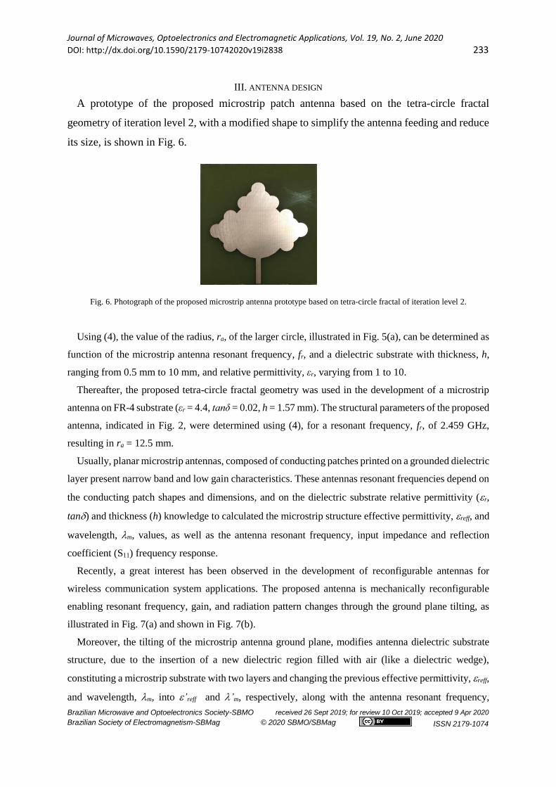
A prototype of the proposed microstrip patch antenna based on the tetra-circle fractal
geometry of iteration level 2, with a modified shape to simplify the antenna feeding and reduce
its size, is shown in Fig. 6.
Fig. 6. Photograph of the proposed microstrip antenna prototype based on tetra-circle fractal of iteration level 2.
Using (4), the value of the radius, ra, of the larger circle, illustrated in Fig. 5(a), can be determined as
function of the microstrip antenna resonant frequency, fr, and a dielectric substrate with thickness, h,
ranging from 0.5 mm to 10 mm, and relative permittivity, εr, varying from 1 to 10.
Thereafter, the proposed tetra-circle fractal geometry was used in the development of a microstrip
antenna on FR-4 substrate (εr = 4.4, tanδ = 0.02, h = 1.57 mm). The structural parameters of the proposed
antenna, indicated in Fig. 2, were determined using (4), for a resonant frequency, fr, of 2.459 GHz,
resulting in ra = 12.5 mm.
Usually, planar microstrip antennas, composed of conducting patches printed on a grounded dielectric
layer present narrow band and low gain characteristics. These antennas resonant frequencies depend on
the conducting patch shapes and dimensions, and on the dielectric substrate relative permittivity (r,
tan) and thickness (h) knowledge to calculated the microstrip structure effective permittivity, reff, and
wavelength, m, values, as well as the antenna resonant frequency, input impedance and reflection
coefficient (S11) frequency response.
Recently, a great interest has been observed in the development of reconfigurable antennas for
wireless communication system applications. The proposed antenna is mechanically reconfigurable
enabling resonant frequency, gain, and radiation pattern changes through the ground plane tilting, as
illustrated in Fig. 7(a) and shown in Fig. 7(b).
Moreover, the tilting of the microstrip antenna ground plane, modifies antenna dielectric substrate
structure, due to the insertion of a new dielectric region filled with air (like a dielectric wedge),
constituting a microstrip substrate with two layers and changing the previous effective permittivity, reff,
and wavelength, m, into ’reff and ’m, respectively, along with the antenna resonant frequency,

Journal of Microwaves, Optoelectronics and Electromagnetic Applications, Vol. 19, No. 2, June 2020
DOI: http://dx.doi.org/10.1590/2179-10742020v19i2838 234
Brazilian Microwave and Optoelectronics Society-SBMO received 26 Sept 2019; for review 10 Oct 2019; accepted 9 Apr 2020
Brazilian Society of Electromagnetism-SBMag © 2020 SBMO/SBMag ISSN 2179-1074
bandwidth, and gain pattern, for example. In this case, the FR-4 substrate structure and conducting patch
shape and dimensions considered in the design of the antenna prototype shown in Fig. 6, are kept
constant.
(a)
(b) (c)
Fig. 7. Mechanically reconfigurable antenna structure. (a) Illustration; (b) Prototype photograph (α = 10); (c) Prototype
photograph (α = 2).
In Fig. 7(b) and (c), a small DC motor is used to move right or left a dielectric ramp coupled
to a motor axis rotation. Depending on the orientation of the motor axis rotation, the ramp
pushes the antenna ground plane up or down, decreasing or increasing the tilt angle α value,
respectively. This enables the antenna to operate at specific resonant frequencies for different
wireless communication applications.
III. RESULTS AND DISCUSSION
Fig. 8 shows the proposed antenna reflection coefficient simulated and measured results at α
= 0º (without tilting the ground plane). The HFSS simulation results are resonant frequency, fr
= 2.459 GHz, reflection coefficient, S11(dB) = -34.90, and relative bandwidth, BW (%) = 2.89.
Measurement results are, fr = 2.457 GHz, S11 (dB) = -28.52, and BW (%) = 3.46%.

Journal of Microwaves, Optoelectronics and Electromagnetic Applications, Vol. 19, No. 2, June 2020
DOI: http://dx.doi.org/10.1590/2179-10742020v19i2838 235
Brazilian Microwave and Optoelectronics Society-SBMO received 26 Sept 2019; for review 10 Oct 2019; accepted 9 Apr 2020
Brazilian Society of Electromagnetism-SBMag © 2020 SBMO/SBMag ISSN 2179-1074
Fig. 8. Simulation and measurements reflection coefficient results of the proposed antenna at α = 0º.
Fig. 9 shows HFSS simulated (gain) radiation pattern at the frequency of 2.459 GHz for both co- and
cross-polarization for α = 0º (without tilting the ground plane). As shown in Fig. 9, in all cases, the
cross-polarization results are 16 dB lower than the co-polarization ones. In addition, the surface current
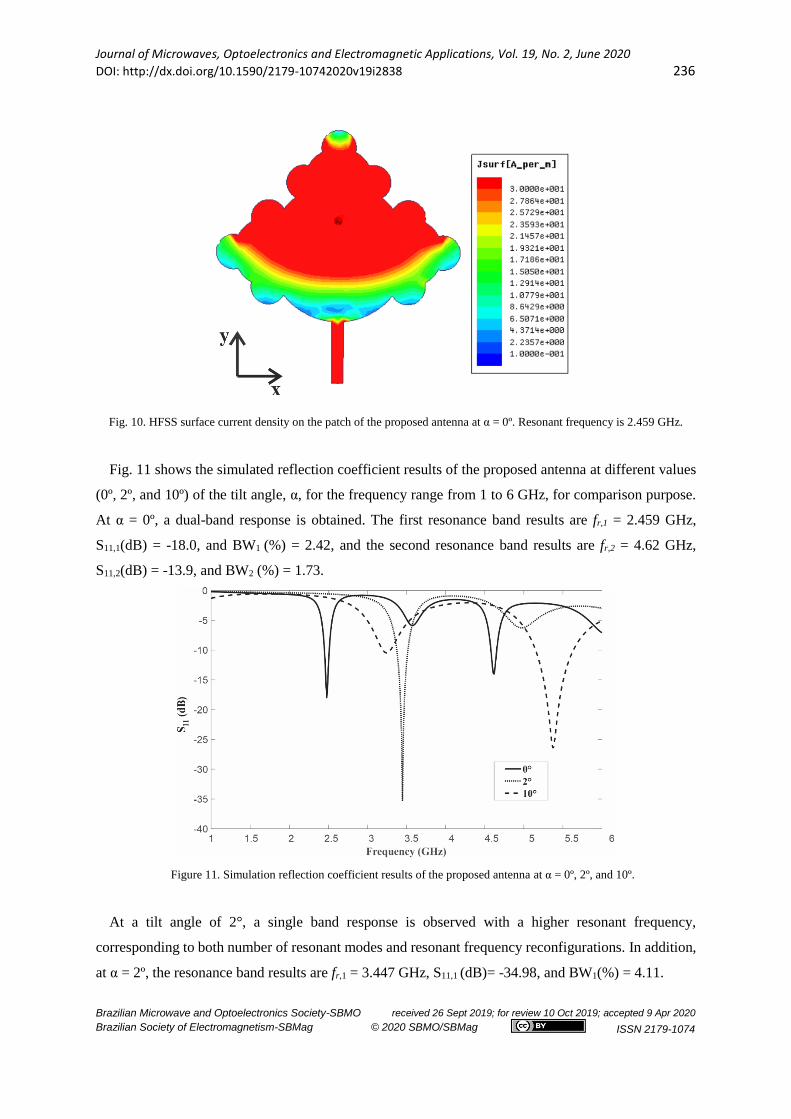
density HFSS simulated results at 2.459 GHz are shown in Fig. 10.
Fig. 9. Simulation 2D gain pattern results of the proposed antenna at α = 0º.
Journal of Microwaves, Optoelectronics and Electromagnetic Applications, Vol. 19, No. 2, June 2020
DOI: http://dx.doi.org/10.1590/2179-10742020v19i2838 236
Brazilian Microwave and Optoelectronics Society-SBMO received 26 Sept 2019; for review 10 Oct 2019; accepted 9 Apr 2020
Brazilian Society of Electromagnetism-SBMag © 2020 SBMO/SBMag ISSN 2179-1074
Fig. 10. HFSS surface current density on the patch of the proposed antenna at α = 0º. Resonant frequency is 2.459 GHz.
Fig. 11 shows the simulated reflection coefficient results of the proposed antenna at different values
(0º, 2º, and 10º) of the tilt angle, α, for the frequency range from 1 to 6 GHz, for comparison purpose.
At α = 0º, a dual-band response is obtained. The first resonance band results are fr,1 = 2.459 GHz,
S11,1(dB) = -18.0, and BW1 (%) = 2.42, and the second resonance band results are fr,2 = 4.62 GHz,
S11,2(dB) = -13.9, and BW2 (%) = 1.73.
Figure 11. Simulation reflection coefficient results of the proposed antenna at α = 0º, 2º, and 10º.
At a tilt angle of 2°, a single band response is observed with a higher resonant frequency,
corresponding to both number of resonant modes and resonant frequency reconfigurations. In addition,
at α = 2º, the resonance band results are fr,1 = 3.447 GHz, S11,1 (dB)= -34.98, and BW1(%) = 4.11.

Journal of Microwaves, Optoelectronics and Electromagnetic Applications, Vol. 19, No. 2, June 2020
DOI: http://dx.doi.org/10.1590/2179-10742020v19i2838 237
Brazilian Microwave and Optoelectronics Society-SBMO received 26 Sept 2019; for review 10 Oct 2019; accepted 9 Apr 2020
Brazilian Society of Electromagnetism-SBMag © 2020 SBMO/SBMag ISSN 2179-1074
At α=10º, a single band response is obtained. The resonance band results are fr,1 = 5.381 GHz,
S11,1(dB) = -26.26, and BW1 (%) = 8.88.
Comparisons between simulated and measured reflection coefficient results of the proposed antenna
with different values of the tilt angle, α, are shown in Fig. 12.
(a)
(b)
(c)
Fig. 12. Simulated and measured reflection coefficient results for the proposed reconfigurable antenna at different tilt angles.
(a) 0º, (b) 2º, and (c) 10°.
Journal of Microwaves, Optoelectronics and Electromagnetic Applications, Vol. 19, No. 2, June 2020
DOI: http://dx.doi.org/10.1590/2179-10742020v19i2838 238
Brazilian Microwave and Optoelectronics Society-SBMO received 26 Sept 2019; for review 10 Oct 2019; accepted 9 Apr 2020
Brazilian Society of Electromagnetism-SBMag © 2020 SBMO/SBMag ISSN 2179-1074
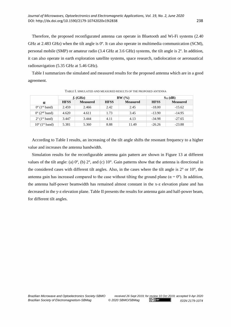
Therefore, the proposed reconfigurated antenna can operate in Bluetooth and Wi-Fi systems (2.40
GHz at 2.483 GHz) when the tilt angle is 0º. It can also operate in multimedia communication (SCM),
personal mobile (SMP) or amateur radio (3.4 GHz at 3.6 GHz) systems, the tilt angle is 2º. In addition,
it can also operate in earth exploration satellite systems, space research, radiolocation or aeronautical
radionavigation (5.35 GHz at 5.46 GHz).
Table I summarizes the simulated and measured results for the proposed antenna which are in a good
agreement.
TABLE I. SIMULATED AND MEASURED RESULTS OF THE PROPOSED ANTENNA
α
fr (GHz) BW (%) S11 (dB)
HFSS Measured HFSS Measured HFSS Measured
0º (1st band) 2.459 2.466 2.42 2.45 -18.00 -15.62
0º (2nd band) 4.620 4.611 1.73 3.45 -13.90 -14.95
2º (1st band) 3.447 3.444 4.11 4.13 -34.98 -27.65
10º (1st band) 5.381 5.360 8.88 11.49 -26.26 -23.88
According to Table I results, an increasing of the tilt angle shifts the resonant frequency to a higher
value and increases the antenna bandwidth.
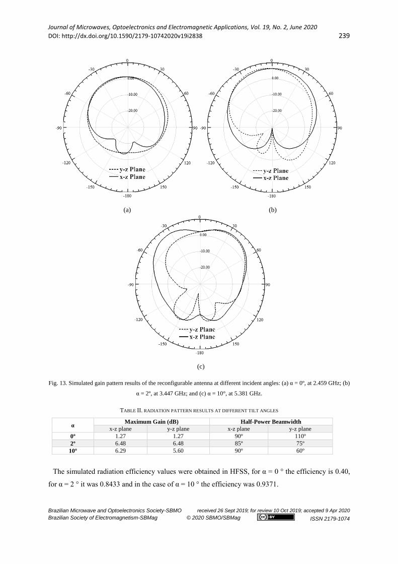
Simulation results for the reconfigurable antenna gain pattern are shown in Figure 13 at different
values of the tilt angle: (a) 0º, (b) 2°, and (c) 10°. Gain patterns show that the antenna is directional in
the considered cases with different tilt angles. Also, in the cases where the tilt angle is 2° or 10°, the
antenna gain has increased compared to the case without tilting the ground plane (α = 0º). In addition,
the antenna half-power beamwidth has remained almost constant in the x-z elevation plane and has
decreased in the y-z elevation plane. Table II presents the results for antenna gain and half-power beam,
for different tilt angles.
Journal of Microwaves, Optoelectronics and Electromagnetic Applications, Vol. 19, No. 2, June 2020
DOI: http://dx.doi.org/10.1590/2179-10742020v19i2838 239
Brazilian Microwave and Optoelectronics Society-SBMO received 26 Sept 2019; for review 10 Oct 2019; accepted 9 Apr 2020
Brazilian Society of Electromagnetism-SBMag © 2020 SBMO/SBMag ISSN 2179-1074
(a) (b)
(c)
Fig. 13. Simulated gain pattern results of the reconfigurable antenna at different incident angles: (a) α = 0º, at 2.459 GHz; (b)
α = 2º, at 3.447 GHz; and (c) α = 10°, at 5.381 GHz.
TABLE II. RADIATION PATTERN RESULTS AT DIFFERENT TILT ANGLES
α Maximum Gain (dB) Half-Power Beamwidth
x-z plane y-z plane x-z plane y-z plane
0º 1.27 1.27 90º 110º
2º 6.48 6.48 85º 75º
10º 6.29 5.60 90º 60º
The simulated radiation efficiency values were obtained in HFSS, for α = 0 ° the efficiency is 0.40,
for α = 2 ° it was 0.8433 and in the case of α = 10 ° the efficiency was 0.9371.

Journal of Microwaves, Optoelectronics and Electromagnetic Applications, Vol. 19, No. 2, June 2020
DOI: http://dx.doi.org/10.1590/2179-10742020v19i2838 240
Brazilian Microwave and Optoelectronics Society-SBMO received 26 Sept 2019; for review 10 Oct 2019; accepted 9 Apr 2020
Brazilian Society of Electromagnetism-SBMag © 2020 SBMO/SBMag ISSN 2179-1074
V. CONCLUSION
An investigation on the properties of tetra-circle fractal inspired microstrip antennas with tilted
ground plane was presented enabling to achieve reconfiguration of the resonant frequencies and
radiation pattern performance. The tetra-circle patch shape enables an easy design based on the
knowledge of the radius of the larger circle, ra, from which the other key dimensions are obtained,
simplifying the antenna synthesis. The synthesis simulation was performed using a simple expression
for ra calculation which was obtained using Ansoft HFSS software and the response surface
methodology.
The proposed synthesis expression for ra calculation provided accurate resultswhen used in microstrip
antenna designs. A prototype of the reconfigurable microstrip antenna was designed and measured at
tilt angles of 0º, 2º and 10º, for comparison purpose. The antenna presented different resonant
frequencies for each angle, confirming the antenna reconfiguration ability. At 2º and 10º tilting angles,
the antenna presented a high gain and became more directive. A small DC motor was used to tilt the
antenna ground plane up and down. Simulated and measured results are in agreement. The proposed
reconfigurable antenna can operate in different systems according to the resonant frequency values
related to the tilting ground plane angle, . At α = 0º, the antenna could be used in Bluetooth and Wi-
Fi systems. At α = 2º, the antenna could be used in multimedia communication (SCM), personal mobile
(SMP) or amateur radio. At α = 10º, it could be used in earth exploration satellite systems, space
research, radiolocation or aeronautical radionavigation.
REFERENCES
[1] C. X. Mao, S. Gao, and Y. Wang, “Broadband high-gain beam-scanning antenna array for millimeter-wave applications,”
IEEE Trans. Antennas Propag. vol. 65, no. 9, pp. 4864-4868, 2017.
[2] B. Singh, N. Sarwade, and K. P. Ray, “Compact series fed tapered antenna array using unequal rectangular microstrip
antenna elements,” Microw. Opt. Technol. Lett., vol. 59, no. 8, pp. 1856-1861, 2016.
[3] H. L. Zhu, S. W. Cheung and T. I. Yuk, “Mechanically pattern reconfigurable antenna using metasurface,” IET
Microwaves, Antennas & Propagation, vol. 9, no. 12, pp. 1331-1336, 2015.
[4] K. Noda, M. Ohkado, B.-K. Nguyen, K. Matsumoto, H. Fujikawa, and I. Shi, “Frequency-tunable microstrip antenna with
liquid actuator using gradually widened transmission line,” IEEE Antennas and Wirel. Propag. Lett., vol. 14, pp. 551-
555, 2015.
[5] J. F. Tsai and J. S. Row, “Reconfigurable square-ring microstrip antenna,” IEEE Trans. Antennas Propag., v. 61, no. 5,
pp. 2857-2860, 2013.
[6] D. Singh, B. Kanaujia, S. Dwari, G. Pandey, and S. Kumar, “Reconfigurable circularly polarized capacitive coupled
microstrip antenna,” Int.J. Microw. Wirel. Technol., vol. 9 n. 4, p. 843-850, 2017.
[7] A. I. Khuri and S. Mukhopadhyay, “Response surface methodology,” WIREs Comput. Stat., vol. 2, 2010, pp. 128–149.
[8] R. H. Myers, I. K. André, and H. C. Walter, “Response surface methodology: 1966-1988,” Technometrics, vol. 31, pp.
137-157, 1989.
[9] J. Costantine, Y. Tawk, S. E. Barbin, and C. G. Christodoulou, “Reconfigurable antennas: design and applications,” Proc.
IEEE, vol. 103, pp. 424-437, 2015.
[10] C. A. Balanis, Antenna Theory – Analysis and Design, Harper & Row, Pub., New York, 1982.
[11] J. Deng, S. Hou, L. Zhao, and L. Guo, "A Reconfigurable filtering antenna with integrated bandpass filters for
UWB/WLAN applications," IEEE Trans. Antennas Propag., vol. 66, pp. 401-404, 2018.
[12] L. Pazin and Y. Leviatan, “Reconfigurable rotated-T slot antenna for cognitive radio systems,” IEEE Trans. Antennas
Propag., vol. 62, pp. 2382-2387, 2014.
[13] P. S. Neethu and T. Sudha, “Patch antenna for wireless LAN systems with polarization reconfigurability,” Nat. Conf.
Commun. Signal Proc. Networking (NCCSN), Palakkad, India, 2014, pp. 1-5.
[14] GuipingJin, Chengyan Li, Tao Zhou, “Frequency reconfigurable antenna for cognitive radio applications,” IEEE Int.
Conf. Commun. Problem-Solving (ICCP), Beijing, China, 2014, pp. 176-179.

Journal of Microwaves, Optoelectronics and Electromagnetic Applications, Vol. 19, No. 2, June 2020
DOI: http://dx.doi.org/10.1590/2179-10742020v19i2838 241
Brazilian Microwave and Optoelectronics Society-SBMO received 26 Sept 2019; for review 10 Oct 2019; accepted 9 Apr 2020
Brazilian Society of Electromagnetism-SBMag © 2020 SBMO/SBMag ISSN 2179-1074
[15] X.-L. Yang, J.-C. Lin, G. Chen and F.-L. Kong, “Frequency reconfigurable antenna for wireless communications using
GaAs FET switch,” IEEE Antennas Wirel. Propag. Lett., vol. 14, pp. 807-810, 2014.
[16] J.-M. Hannula, J. Holopainen, and V. Viikari, “Concept for frequency-reconfigurable antenna based on distributed
transceivers,” IEEE Antennas Wireless Propag. Lett., vol. 16, pp. 764-767, 2017.
[17] S. Danesh, S. K. A. Rahim, M. Abedian, and M. R. Hamid, “A compact frequency-reconfigurable dielectric resonator
antenna for LTE/WWAN and WLAN applications,” IEEE Antennas Wirel. Propag. Lett., vol. 14, pp. 486-489, 2015.
[18] K. S. Ryu and A. A. Kishk, “Ultrawideband dielectric resonator antenna with broadside patterns mounted on a vertical
ground plane edge,” IEEE Trans. Antennas Propag., vol. 58, pp. 1047-1053, 2010.
[19] H. Rajagopalan, J. M. Kovitz, and Y. Rahmat-Samii, “MEMS reconfigurable optimized E-shaped patch antenna design
for cognitive radio,” IEEE Trans. Antennas Propag., vol. 62, pp. 1056-1064, 2014.
[20] P. Kakaria and R. Nema, “Review and survey of compact and broadband microstrip patch antenna,” Int. Conf. Advances
Eng.& Technol. Res. (ICAETR), Unnao, India, 2014, pp. 1-5.