syntax line 25-28 cutting and shaping equipment - … - syntaxline25-28_uk.pdf · 25-28 cutting and...
TRANSCRIPT

Cu
ttin
g a
nd
sh
apin
g e
qu
ipm
ent
the history of innovation
Syntax Line 25-28Cutting and shaping equipment
www.mepgroup.com

Syntax Line 25-28
The SYNTAX LINE high productivity performance is guaranteed both in case of large series production (repeated forms of the same diameter) as well as for processing of individual building elements such as beams, columns (different diameters, shapes and sizes), when the “classification” of production is a must. The adoption of a full automated cut and bend unit such as the SYNTAX LINE allows to use less machines, to reduce the workforce and therefore to cut the cost per unit of weight of the finished products.
LOW COST PRODUCTIVITY
The SYNTAX LINE is a complete and fully automated cut and bend station for processing of stock rebar.The complete production cycle (loading, cut and bend) is conceived to be carried out in full automation, without requiring any manual handling by the operator. The large extent of equipment functions and the flexibility in programming the production cycles, makes the SYNTAX LINE capable to manage any production requirement providing an outstanding quality of the finished products.
WE AUTOMATE THE REBAR PROCESSING

Patented solutions for an unmatched precision
The SYNTAX LINE is specifically designed to cover all production phases, that traditionally require manual activity, in a very fast and full automated process.There is no slow-down in production, all working cycles are carried out contnuously and perfectly optimized.Maximum productivity is guranteed at any working load condition.
The optional automatic loading system (patented) selects the diameter of the bars, alignes and loads 1 or 2 bars depending on the program list, thus creating a continuous optimized working cycle.The device uses a mechanical arm equipped with magnets that lift the bars from the bundle.A magnet draws and counts every single bar with extreme precision, avoiding counting errors (loading one bar instead of two) which would distort the quantities to be produced, as well as compromising the optimization already programmed.The reliability of the working cycle is thus guaranteed.
PRECISE COUNTING MATTERS
The bar alignment device is essential when working double bar because it guarantees correct measurement tolerances.The device aligns the bars before they are counted and loaded into the machine, without compromising the productivity of the equipment.
WE ALIGN EVERYSINGLE BAR
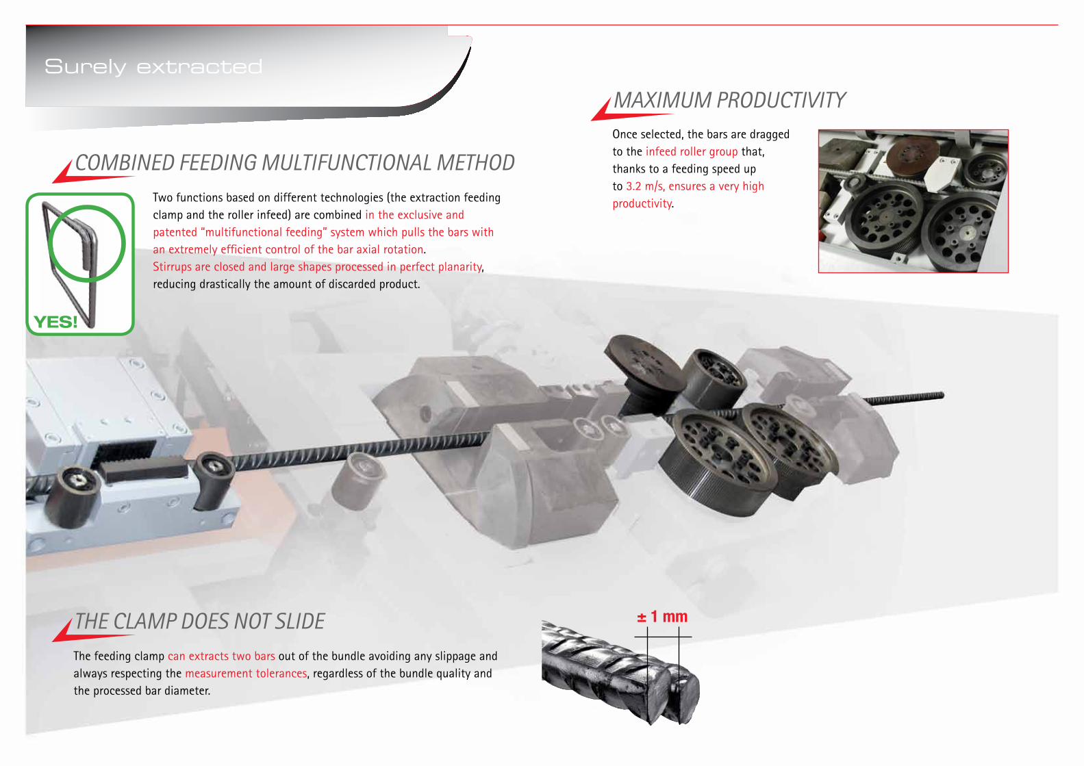
Two functions based on different technologies (the extraction feeding clamp and the roller infeed) are combined in the exclusive and patented “multifunctional feeding” system which pulls the bars with an extremely efficient control of the bar axial rotation.Stirrups are closed and large shapes processed in perfect planarity, reducing drastically the amount of discarded product.
COMBINED FEEDING MULTIFUNCTIONAL METHOD
THE CLAMP DOES NOT SLIDE ± 1 mm
Once selected, the bars are dragged to the infeed roller group that, thanks to a feeding speed upto 3.2 m/s, ensures a very high productivity.
MAXIMUM PRODUCTIVITY
The feeding clamp can extracts two bars out of the bundle avoiding any slippage and always respecting the measurement tolerances, regardless of the bundle quality and the processed bar diameter.
YES!
Surely extracted

1While the first shear ( ) makes the intermediate cuts , the second shear ( )cuts the tail of the bar only after the achievement of the right development .In this way we avoid the classic method which provides a first alignment cut of the bars maked completely random, which produces differences in the length not predictable.
The two cutting units use universal knives, for all diameters processed with 4 cutting facets.
UNIVERSAL BLADES
The scrap is managed according to its length. In case it is less than 700 mm, the end of the bar is cut and separated from the rest of the production by automatic collection in a dedicated outside bin.In the case of longer lengths, the piece is classified as offcut, then extracted and stored in a dedicated pocket of the mobile collection cart and prevented from being mixed up with the rest of running production.This process is full automated and it does not require any manual intervention by the operator with consequent downtime of the machine.
SCRAP: NO MORE A PROBLEM
Generally the actual and exact length of stock rebars is not known, rather it is always longer than 12m or whatever is the nominal length.Without having measured the length at first, it is uncertain to grant the tollerances on the following cut sequence. This patented method contemplates the use of two indipendent shears that ensure precision and maximizing the use of each individual stock rebar since the machine is designed to remove offcuts of any size.
Two shears for maximum precision
± 1 mm2

Secondary feeding unit: a patented system
The Secondary feeding unit lets you use a patented method that allow to produce shapes bent on both sides using one bending unit instead of two.
The working cycle is considerably simplified and speed up, having eliminated all the time related to transfer the wires at the second bending unit and those required for the change of two bending pins related bending angles calibrations.
A DOUBLE TRACTION FOR ANY SHAPE
This patented method provides the simultaneous exit of the secondary feeding unit ( ) and the bending unit ( ) among the working plane, avoiding the collision between the shape and the cutting unit ( + ) during the pulling back progress.
This solution enables the production of shaped products of all forms and sizes using the entire working surface.
NO RESTRICTIONS ON SHAPES AND DIMENSIONS
GRAVITY FOR QUALITYExploiting the effect of gravity during the bending phase we obtain shapes always coplanar.
The rollers of the secondary feeding unit open and close before each bend, allowing the shape “to rely” on the work surface and as a result of gravity.
The subsequent bends will always aligned with those already executed, canceling out any residual phenomenon of rotation.

The mobile collection cart allow the selective separation of finished products according to the optimized list. The process automation allows to manage multiple open positions (different sizes and shapes) that comes from the same bar, without any stop to the production cycle.
SYNTAX LINE is equipped with single block bending pins (patented) with self-locking device.They are made in accordance with the international regulations and allowing fast change at the same time as the diameter change a fast production restart.
THE FASTEST BENDING PINS CHANGE
The automatic collection devices allow to maintain an high productivity level of the factory, reducing the downtime normally required for the evacuation of the products produced.
COLLECTING AUTOMATICALLY MANAGEMENT OF THE BUNDLESThe mobile holding rack allows the bundles’ storage within 8 or more compartments that depending on the diameter to be processed aligns to the optional automatic loading system reaching a continuous and automatic production cycle.A dedicated software (available with the automatic loading system) monitors the remaining quantity of each compartment in order to plan the bundle loading for the completion of the programmed list.
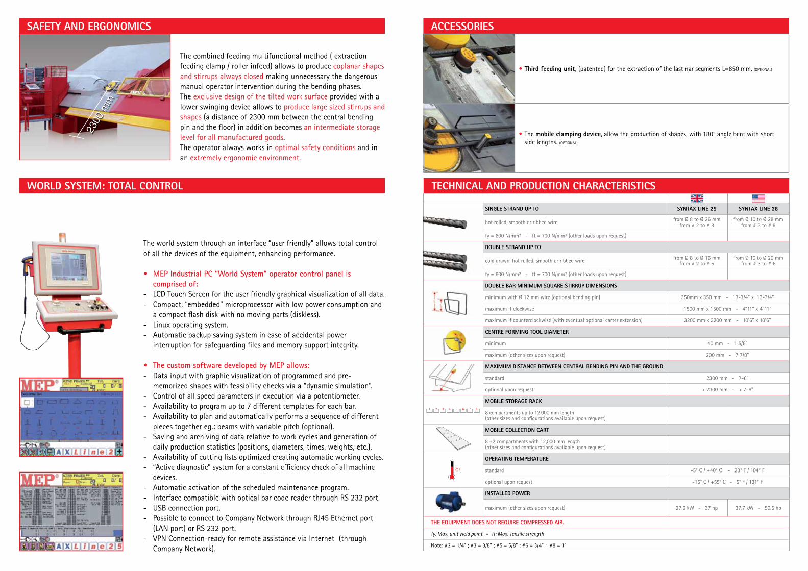
SAFETY AND ERGONOMICS
The world system through an interface “user friendly” allows total control of all the devices of the equipment, enhancing performance.
• MEPIndustrialPC“WorldSystem”operatorcontrolpaneliscomprisedof:
- LCD Touch Screen for the user friendly graphical visualization of all data.- Compact, “embedded” microprocessor with low power consumption and
a compact flash disk with no moving parts (diskless).- Linux operating system.- Automatic backup saving system in case of accidental power
interruption for safeguarding files and memory support integrity. • ThecustomsoftwaredevelopedbyMEPallows:- Data input with graphic visualization of programmed and pre-
memorized shapes with feasibility checks via a “dynamic simulation”.- Control of all speed parameters in execution via a potentiometer.- Availability to program up to 7 different templates for each bar.- Availability to plan and automatically performs a sequence of different
pieces together eg.: beams with variable pitch (optional).- Saving and archiving of data relative to work cycles and generation of
daily production statistics (positions, diameters, times, weights, etc.).- Availability of cutting lists optimized creating automatic working cycles.- “Active diagnostic” system for a constant efficiency check of all machine
devices.- Automatic activation of the scheduled maintenance program.- Interface compatible with optical bar code reader through RS 232 port.- USB connection port. - Possible to connect to Company Network through RJ45 Ethernet port (LAN port) or RS 232 port. - VPN Connection-ready for remote assistance via Internet (through
Company Network).
The combined feeding multifunctional method ( extraction feeding clamp / roller infeed) allows to produce coplanar shapes and stirrups always closed making unnecessary the dangerous manual operator intervention during the bending phases. The exclusive design of the tilted work surface provided with a lower swinging device allows to produce large sized stirrups and shapes (a distance of 2300 mm between the central bending pin and the floor) in addition becomes an intermediate storage level for all manufactured goods.The operator always works in optimal safety conditions and in an extremely ergonomic environment.
2300
mm
WORLD SYSTEM: TOTAL CONTROL
ACCESSORIES
C°
L
1 2 3 4 5 6 7 8
• Third feeding unit, (patented) for the extraction of the last nar segments L=850 mm. (OPTIONAL)
• The mobile clamping device, allow the production of shapes, with 180° angle bent with short side lengths. (OPTIONAL)
SINGLE STRAND UP TO SYNTAX LINE 25 SYNTAX LINE 28
hot rolled, smooth or ribbed wire from Ø 8 to Ø 26 mmfrom # 2 to # 8
from Ø 10 to Ø 28 mm from # 3 to # 8
fy = 600 N/mm² - ft = 700 N/mm² (other loads upon request)
DOUBLE STRAND UP TO
cold drawn, hot rolled, smooth or ribbed wire from Ø 8 to Ø 16 mmfrom # 2 to # 5
from Ø 10 to Ø 20 mmfrom # 3 to # 6
fy = 600 N/mm² - ft = 700 N/mm² (other loads upon request)
DOUBLE BAR MINIMUM SQUARE STIRRUP DIMENSIONS
minimum with Ø 12 mm wire (optional bending pin) 350mm x 350 mm - 13-3/4” x 13-3/4”
maximum if clockwise 1500 mm x 1500 mm - 4”11” x 4”11”
maximum if counterclockwise (with eventual optional carter extension) 3200 mm x 3200 mm - 10’6” x 10’6”
CENTRE FORMING TOOL DIAMETER
minimum 40 mm - 1 5/8”
maximum (other sizes upon request) 200 mm - 7 7/8”
MAXIMUM DISTANCE BETWEEN CENTRAL BENDING PIN AND THE GROUND
standard 2300 mm - 7-6”
optional upon request > 2300 mm - > 7-6”
MOBILE STORAGE RACK
8 compartments up to 12.000 mm length(other sizes and configurations available upon request)
MOBILE COLLECTION CART
8 +2 compartments with 12,000 mm length(other sizes and configurations available upon request)
OPERATING TEMPERATURE
standard -5° C / +40° C - 23° F / 104° F
optional upon request -15° C / +55° C - 5° F / 131° F
INSTALLED POWER
maximum (other sizes upon request) 27,6 kW - 37 hp 37,7 kW - 50.5 hp
THE EQUIPMENT DOES NOT REQUIRE COMPRESSED AIR.
fy: Max. unit yield point - ft: Max. Tensile strength
Note: #2 = 1/4” ; #3 = 3/8” ; #5 = 5/8” ; #6 = 3/4” ; #8 = 1”
TECHNICAL AND PRODUCTION CHARACTERISTICS

MEP
S.p
.a. r
eser
ves
the
right
to c
hang
e te
chni
cal d
ata
with
out p
rior n
otic
e.11
.201
2
MEP Macchine Elettroniche Piegatricivia Leonardo Da Vinci, 20I - 33010 Reana del Roiale (UD) - ITALYTel. +39 0432 851455Fax +39 0432 880140
MEP BrasilRua Bom Jesus da Cachoeira, nº 100Parque Edu ChavesCEP 02236-020 - Sao Paulo - BRASILTel. +55 11 2240.4610 - 2240.4553Fax +55 11 2240.4610 - 2240.4553
MEP France S.A.8 bis, rue des OziersBP 40796 Zone d’Activités du Vert Galant95004 St. Ouen L’Aumône FRANCE Tel. +33 1 34300676Fax +33 1 34300672
MEP Nord-Europe GmbHBrienner Strasse 55D-80333 München GERMANY Tel. +49 089 41610829
MEP Polska Sp. z o.o.ul. Józefowska 13/A93-338 Łódź POLAND Tel. +48 42 645 7225Fax +48 42 645 7058
MEP Vostok OOOУл.Новаторов, 36 корп.3 Офис XXIV119421 Москва РоссияTel./Fax: +7 495 745 04 90
MEP Asia Co., Ltd.1303 Ho, 301-Dong, Bucheon Techno Park345 Sukcheon Ro, Ojung-GuBucheon, Gyunggi-Do - SOUTH KOREATel. +82 32 329 1956Fax +82 32 329 1957