synchronous down counter
TRANSCRIPT

GYANMANJARI INSTITUTE OF TECHNOLOGY

Prepared by: Ronak SutariyaEnrolment No: 151290107052Branch: Computer Engineering
Subject: Digital Electronics (2131004)Topic: Synchronous Down Counter
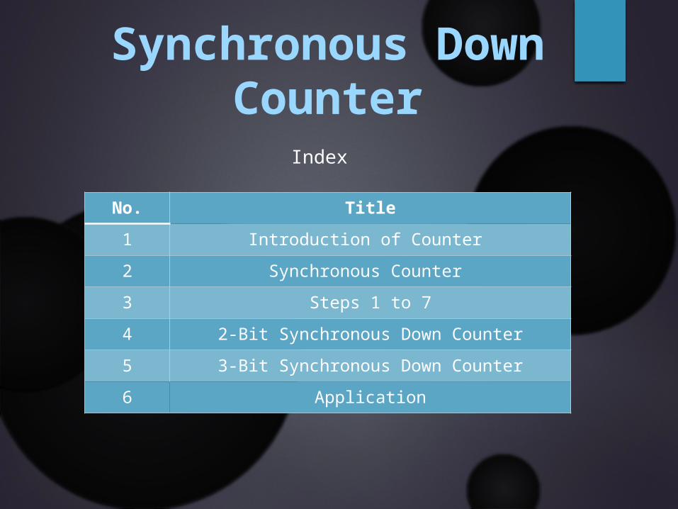
Index
No. Title1 Introduction of Counter 2 Synchronous Counter 3 Steps 1 to 74 2-Bit Synchronous Down Counter5 3-Bit Synchronous Down Counter6 Application
Synchronous Down Counter
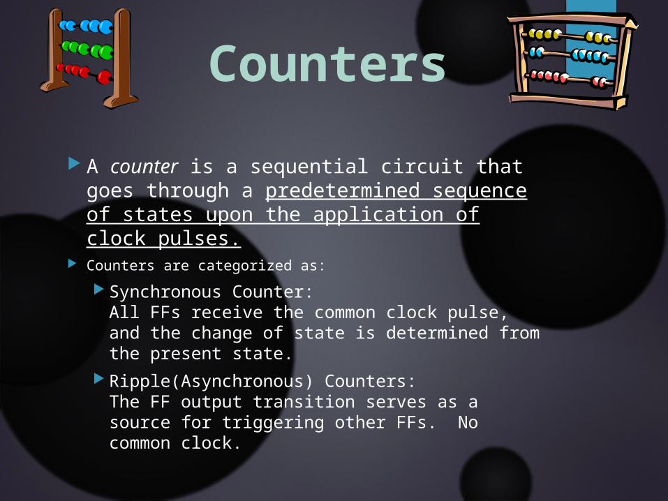
A counter is a sequential circuit that goes through a predetermined sequence of states upon the application of clock pulses.
Counters are categorized as: Synchronous Counter:
All FFs receive the common clock pulse, and the change of state is determined from the present state.
Ripple(Asynchronous) Counters: The FF output transition serves as a source for triggering other FFs. No common clock.
Counters
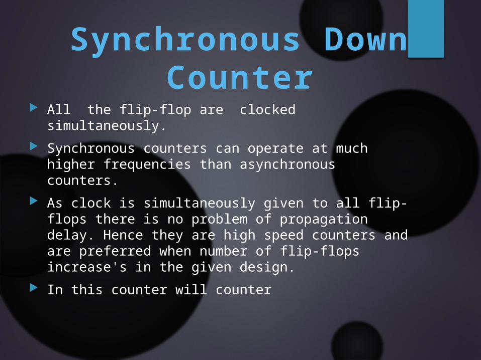
All the flip-flop are clocked simultaneously. Synchronous counters can operate at much higher
frequencies than asynchronous counters. As clock is simultaneously given to all flip-flops there
is no problem of propagation delay. Hence they are high speed counters and are preferred when number of flip-flops increase's in the given design.
In this counter will counter
Synchronous Down Counter
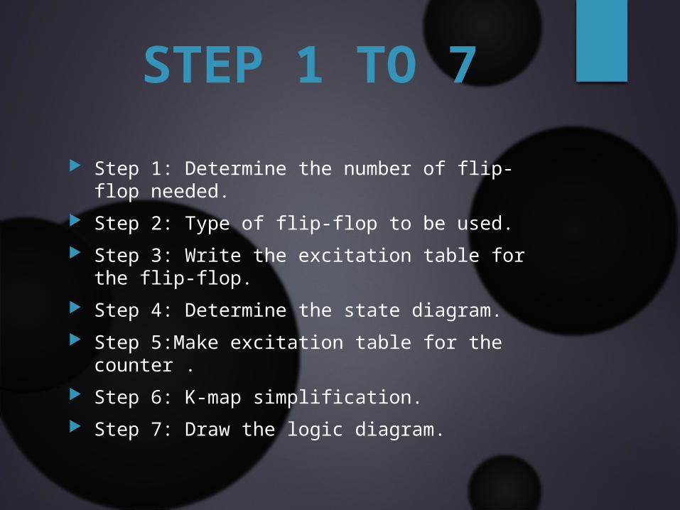
Step 1: Determine the number of flip-flop needed.
Step 2: Type of flip-flop to be used. Step 3: Write the excitation table for the flip-
flop. Step 4: Determine the state diagram. Step 5:Make excitation table for the counter . Step 6: K-map simplification. Step 7: Draw the logic diagram.
STEP 1 TO 7
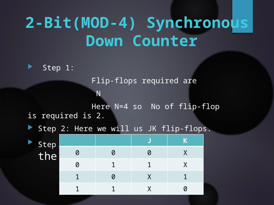
Step 1: Flip-flops required are N Here N=4 so No of flip-flop is required is 2. Step 2: Here we will us JK flip-flops. Step 3: Excitation table for the JK
flip-flop
J K0 0 0 X0 1 1 X1 0 X 11 1 X 0
2-Bit(MOD-4) Synchronous Down Counter

Step: 4 State Diagram
00
11
10
01

Step: 5 Excitation table for the 2-bit down counter .
Present state Next state Flip-Flop input
0 0 1 1 1 X 1 X
0 1 0 0 0 X X 1
1 0 0 1 X 1 1 X
1 1 1 0 X 0 X 1
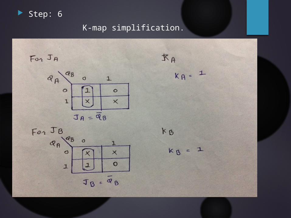
Step: 6K-map simplification.
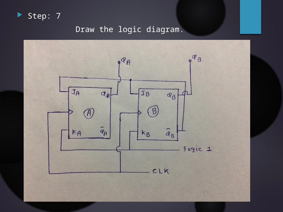
Step: 7 Draw the logic diagram.
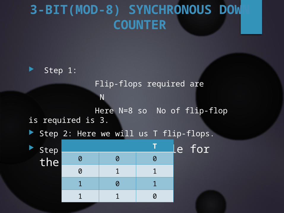
Step 1: Flip-flops required are N Here N=8 so No of flip-flop is required is 3. Step 2: Here we will us T flip-flops. Step 3: Excitation table for the T
flip-flop
T0 0 00 1 11 0 11 1 0
3-BIT(MOD-8) SYNCHRONOUS DOWN COUNTER

Step: 4 State Diagram
000111
110
101100
011
010
001
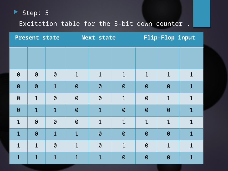
Step: 5 Excitation table for the 3-bit down counter .
Present state Next state Flip-Flop input
0 0 0 1 1 1 1 1 10 0 1 0 0 0 0 0 10 1 0 0 0 1 0 1 10 1 1 0 1 0 0 0 11 0 0 0 1 1 1 1 11 0 1 1 0 0 0 0 11 1 0 1 0 1 0 1 11 1 1 1 1 0 0 0 1
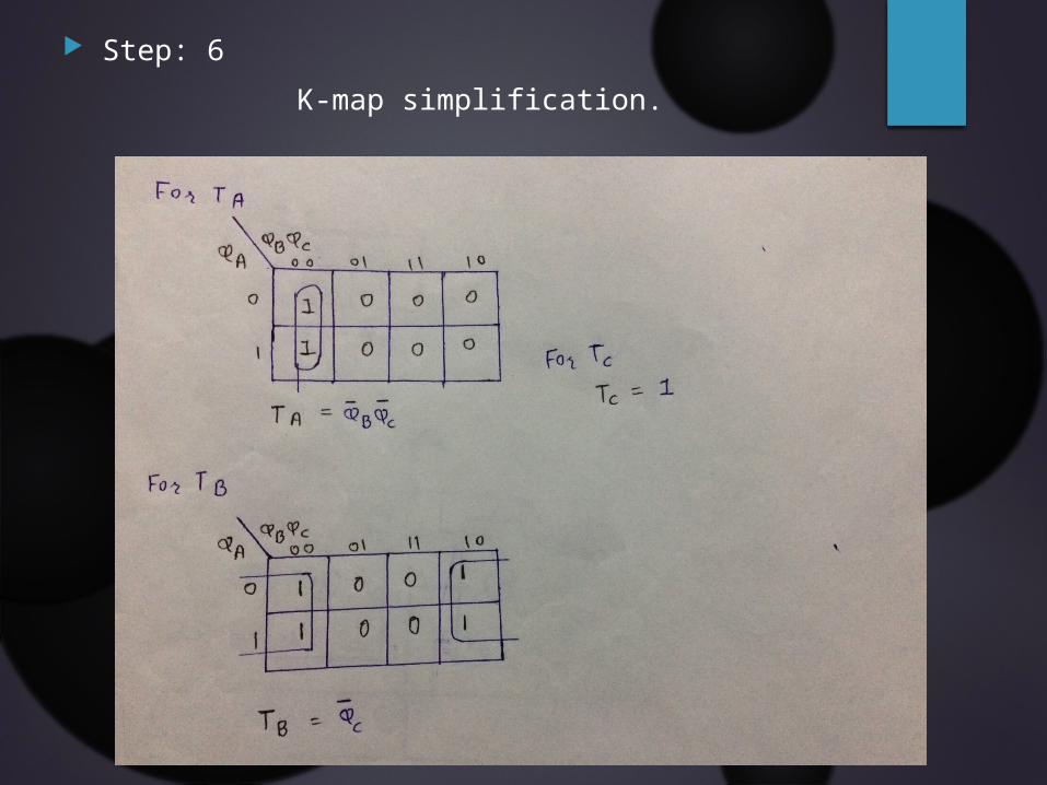
Step: 6K-map simplification.
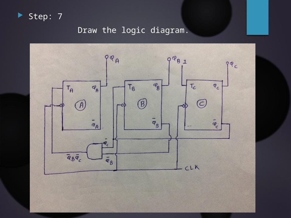
Step: 7 Draw the logic diagram.

Thank You.