symes saw hand out ni j 2010
TRANSCRIPT
7/28/2019 Symes Saw Hand Out Ni j 2010
http://slidepdf.com/reader/full/symes-saw-hand-out-ni-j-2010 1/12
Knife and Saw MarkKnife and Saw Mark
Analysis on Bone Analysis on Bone
Steven A. SymesChristopher W. Rainwater
Susan M. T. Myster Erin N. Chapman
Ivana Wolff
Not for citation or quotation without the author’s permission
Department of Applied Forensic SciencesMercyhurst CollegeErie, Pennsylvania
Contact: [email protected] funded by the National Institute of Justice and the National Forensic Academy

7/28/2019 Symes Saw Hand Out Ni j 2010
http://slidepdf.com/reader/full/symes-saw-hand-out-ni-j-2010 2/122
Knife and Saw Mark Analysis on Bone
Syracuse University Dialogues in ForensicScience:Trauma I
Presenters: Steven A. Symes PhD, DABFA
Susan M. T. Myster PhD, DABFA
Christopher W. Rainwater, MSErin N. Chapman, BA
Ivana Wolff
I Introduction to Trauma
1 Sources of traumaÆ Blunt; Ballistic;
Sharp; Burn; Healing
• Description of each type
2 Toolmarks overlooked
• Discussion of the potential of
dismemberment interpretation
• Current Status in Toolmark Analysis in Bone
3 Objectives of Talk
II Introduction to Knives
1 Description of knife cut mark
characteristics and terminology
2 Anatomy of a cut
• Serrated
• Striae
• Patterned
III Demonstration of Knife Stab Wound
(KSW) vs Knife Cut Wounds (KCW) vs.
Knife Chopping
1 Knife stab wounds description and
case study exemplars
2 KSW in cartilage
3 KSW in bone
IV Introduction to Saws
1 General description of saws
2 Anatomy of a cut
• Kerf
• SizeÆ tooth width, kerf width,
distance between teeth (if serrated)
• Set
• ShapeÆ kerf floor: edge; trough
• Power
• DirectionÆ kerf flare
∗ Direction of progress
∗ Direction of stroke (power)
3 Class (not type) characteristics help narrow field
of potential saws/tools
4 Saw Terminology and Characteristics
5 Information contained in handout
6 Brief description and example of each
V Description of Saw Trauma Analysis using Case
Studies
1 Minnesota Dismemberment (Hand Saw)
2 New York serial killer
3 San Jose (Power Saw)
4 Tennesse (Pull Saw)
4 Tennessee (Chain Saw)
VI Misconceptions Common amongst Anthropologists – Analysis of Bone Trauma
1 Use of microscopes and scanning electron
microscopes
2 Analysis of cut surfaces without a microscope
3 Straight cut surface indicates a power saw
4 Cut surfaces do not reveal diagnostic
characteristics
5 Hesitation marks?
6 Anthropologists need to measure and quantify
everything
VII Practical Demonstration
1 Using the ELMO and Saw Mark Data
Collection Sheet Dr. Symes will go through the
analysis of an exemplar case
2 The class will split into groups
• A cut deer metapodial will be analyzed and,
using the Saw Mark Data Collection Sheet,
results will be compared to a short list of
potential saws in the back of manual
VIII Final discussion of relevance of analysis
1 Comparison of anthropological vs. toolmark
analyst approach
2 Class vs. individual characteristics
3 Comparison of equipment—is it possible to do
toolmark analysis for class comparisons on a
comparison microscope?

7/28/2019 Symes Saw Hand Out Ni j 2010
http://slidepdf.com/reader/full/symes-saw-hand-out-ni-j-2010 3/12 3
Symes et al., - Mercyhurst College
Introduction to Saw Mark Analysis on Bone
It is important to understand a few basic concepts about saws and saw blade action before attempting to interpret
saw marks in bone. All saws have teeth. As saw teeth cut into bone a groove, or kerf, is formed. Saw mark analysis
essentially examines saw cut kerfs. A kerf can be defined as the walls and floor of a cut. Floors are expressed in
false-starts and occasionally in break-away spurs. Kerf floors, when present, offer the most information about
the points of each tooth and the relationship of the points to each other or the set (lateral bending) and number
of teeth per inch. Kerf walls offer information about the sides of the teeth. Wall striae commonly represent only
those teeth set to that particular side; while shape, depth, and frequency of these striae may represent the shape of
the blade, the amount of energy transferred to the material, and the motion in which the blade travels to cut bone
(Symes 1992). The object of saw mark analysis is to recognize characteristics on kerf walls and floors that may
accurately reveal:
1. The dimensions and shape of the blade and teeth of a saw
2. How the tool was powered, mechanically or manually
3. How a tool was used to accomplish the dismemberment or mutilation.
Individual characteristics are subject to interpretations of positive identification, consistency, elimination
insufficient results, and unsuitable comparisons (AFTE Criteria for Identification Committee Report 1990:276-
277). However, the narrowing of potential saws is facilitated by class (not individualizing) characteristics. This
narrowed field of tools can aid in the search for an appropriate tool utilized in a crime and the documentationof criminal behavior. With a standardized analysis of saw marks, the following class characteristics can be
identified:
1. Saw Size
2. Saw Set
3. Saw Shape
4. Saw Power
5. Direction of Saw Motion
This manual is organized using these five class characteristics. Each characteristic is followed by definitions o
the features used in determining that characteristic. Each definition is marked with the most appropriate location
of the saw cut by which to observe that feature, whether it be kerf floor (KF), kerf wall (KW), break-away spur(BA), or false start (FS)
Introductory Terminology Kerf
The walls and floor of a cut. Floors are expressed in false-starts and occasionally in break-away spurs. Kerf floors
when present, offer the most information about the points of each tooth and the relationship of the points to each
other or the set (lateral bending) and number of teeth per inch (TPI). Kerf walls can also offer information about
teeth per inch, saw power, and direction of cut.
Break-Away Spur The break-away spur is a projection of uncut bone at the terminal end of the cut
after the force breaks the remaining tissue which commonly occurs on the stable
end of the bone. The break-away spur is often as diagnostic as the kerf floor. The
size of the spur often depends on the amount force applied across the bone resulting
in a fracture of the bone. For instance, the weight of a handheld circular power saw
or chain saw often produces a large break-away spur.
False Starts
False start kerfs are cuts that do not completely section bone and are composed of two initial corners, two walls,
two floor corners, and a floor. These are not considered ‘hesititation’ marks.

7/28/2019 Symes Saw Hand Out Ni j 2010
http://slidepdf.com/reader/full/symes-saw-hand-out-ni-j-2010 4/124
Knife and Saw Mark Analysis on Bone
Saw Size
Blade Width
Minimum Kerf Width. This is simply a measurement of the width of a kerf. The minimum
kerf width is directly related to the width of the set of the blade.
Teeth Per Inch (TPI)
This is literally the number of teeth per inch.
It is a measure of the number of completely
occurring (not just points) teeth per inch. There
is one more point per inch (ppi) than there are
teeth per inch.
Tooth Hop. Striae across the face of the bone generally progress in a
straight pattern. With close observation, the residual kerfs (striations)
occasionally show patterned hopping or predictable waves. Blade
hopping is created as teeth begin to enter the kerf and each successive
tooth strikes bone, which produces movement of the whole blade.Measuring from peak to peak or dip to dip of each wave indicates the
distance between teeth of the saw. It has been demonstrated that tooth
hop can occur with a variety of saws and accurately indicates spacing
of saw teeth. (KW)
Pull Out Striae (Tooth Scratch). Pull out striae are simply the presence of perpendicular striae on the cu
surface of the bone. These are created when the saw is withdrawn from the kerf in mid-stroke. This has been
recognized by Bonte (1975:319) as appearing “vertical to the sawing level which extend[s] over several saw
marks . . . [and] corresponds, with normally set saws, to twice the distance between the teeth.” Pull out striae are
characteristics that do not easily stand alone and are most useful when used to corroborate other more reliable
estimations of tooth distance. Unfortunately the phrase “normally set saws” is a misleading one. Alternatingset saws can leave this type of pattern but a saw with a raker set may leave striae that represent the distance of
three rather than two teeth. (KW)
Harmonics. Saw mark harmonics are described as peaks and valleys exhibited three-dimensionally in bone
cross sections. Harmonic oscillations are found to exist in nearly all blades with alternating set teeth, and are
the direct result of normal cutting action in hand and mechanically powered saws. Harmonics are simply the
expression of blade drift progress and are good indicative characteristics of blade set and TPI. (KW)
Tooth Imprint and Floor Dip. These are resultant of saw teeth combining actions to cut a kerf
floor in bone. When the floor of the kerf is examined on end, the seemingly flat-bottomed kerf may
actually be notched or wavy. Tooth imprints and floor dip are residual imprints from tooth points
in the kerf floor created after a saw is interrupted in the cutting stroke. Consecutive tooth imprint
features can be measured in false starts and break-away spurs to represent the distance between
teeth, indicate the set (shape) of the blade and indicate the shape of the individual tooth. (Andahl
1978:36-37; Symes 1992). (KF)
Tooth Width
Saw tooth width can be calculated in two ways, measurement of floor patterns and measurement of residual tooth
trough. Floor patterns give an average estimation of saw tooth width while the residual tooth image, if properly
interpreted, produces an accurate image of an actual tooth. (KF)

7/28/2019 Symes Saw Hand Out Ni j 2010
http://slidepdf.com/reader/full/symes-saw-hand-out-ni-j-2010 5/12 5
Symes et al., - Mercyhurst College
Saw SetThere are three major types of saw tooth set describing
the lateral bend of teeth; alternating, raker, and wavy. A
cheaper blade may exhibit no set if there is no lateral bend
to the teeth.
Alternating Set
Each subsequent tooth is laterally bent to the opposite side
in an alternating pattern.
Blade Drift. There are certain drift actions that all blades
with alternating set teeth follow since saw teeth are set
to produce a cut wider than the saw blade. This pattern
of teeth drifting across the kerf floor is defined here as
saw blade drift, where every tooth entering the material
creates a direction change in the tooth carving the bone.
(KF)
Bone Islands. Bone islands are acharacteristic associated with alternating
set blades and blade drift. A wider set
increases blade drift and leaves material
in the midline of the kerf. (KF)
Raker Set
Teeth are laterally set to opposites similar to the pattern in
alternating set saws. The raker set, however, introduces a
tooth with no lateral bend subsequent to the two teeth set to
either side.
Wavy Set
In wavy set blades, teeth are laterally bent in groups. The number
of teeth in a group varies and this is most typically seen in fine-
toothed hacksaw blades.
Saw ShapeShape applies to the contour of the blade, the tooth as it is cut out
of the saw blade, and if the teeth are filed at an angle. The most
common classifications are rip and crosscut saws. These styles are
important in that each function in a different manner to effectivelycut different types of material.
Contour
Flat. Typical straight blades, inclusive of both hand- and
mechanically-powered saws produce a flat-bottomed kerf.
(KF)
Curved. Curved blades (such as circular saws) and flexible blades (such as gigli saws) will leave a curved ker
floor. (KF)

7/28/2019 Symes Saw Hand Out Ni j 2010
http://slidepdf.com/reader/full/symes-saw-hand-out-ni-j-2010 6/126
Knife and Saw Mark Analysis on Bone
Tooth Orientation
Tooth orientation is diagnosed in concert with the
direction of sawing motion. The confluence of
features visible in analyzing saw direction will allow
for a determination of whether or not a blade’s power
stroke is occurring on the push or the pull.
Pull Saw. A typical “Japanese” saw cuts on the
pull stroke. It has a thinner blade and produces lessmaterial waste which, in turn, creates a narrower
kerf. In general, pull saws have smaller teeth and
more teeth per inch producing a cleaner cut but at
a slower rate than a push saw.
Push Saw. A typical “Western” saw cuts on the push stroke. It has a wider blade and produces more materia
waste which, in turn, creates a wider kerf. In general, push saws have larger teeth and the push stroke is
more powerful giving the cuts a more
accurate and efficient action than a
push saw.
Tooth Angle
Rip. The teeth of a rip saw are not
angled or filed. The teeth are simply
notched out of the blade. As such,
these saws essentially chisel out
material rather than cut it. Rip saws
are designed to cut with the grain of
wood.
Crosscut. A crosscut saw has teeth
that have been filed to an angle. The
filing allows each tooth to act as a
tiny blade which will cut through
material. Crosscut saws are designed
to cut across the grain of wood.
Saw Power, Hand vs. MechanicalSeparating hand powered from mechanically powered saws is approached in by the examination of three
characteristics; consistency of cut, energy transfer, and material waste. All characteristics increase with
mechanically powered saws.
Consistency of Cut
Consistency of cut is anticipated in continuous cut power saws, where the blade continuously cuts material at
high speeds. However, this consistency is evident in all power saws, even those with reciprocating actions. Hand
powered saws typically exhibit an inconsistency in cut evident on the kerf wall. (KW)
Energy Transfer
Mechanically powered saws increase energy transfer to cut bone. Increased tooth speed, saw weight, and torque
lead to a tendency to inadvertently discontinue a cut. Because of the ease of the cut, it is not important to reinsert

7/28/2019 Symes Saw Hand Out Ni j 2010
http://slidepdf.com/reader/full/symes-saw-hand-out-ni-j-2010 7/12 7
Symes et al., - Mercyhurst College
the blade in the kerf that was initially started. The opposite tendency is true in hand powered saws as it is more
efficient to reinsert the blade in the false start. (FS)
Material Waste
Power saws are generally characterized as wasteful of material. This may be accredited to the stout blade design
or the “ease” of producing a cut. If power saw cuts are produced with little energy expended, it is likely that more
cuts are produced and more material is wasted. (FS)
Direction of Saw MotionCutting Stroke
Cutting stroke is defined as a continuous action or a single direction of a reciprocating action that produces a
majority of the cut. If an equal force is applied to a reciprocating blade, the direction of stroke cutting or chiseling
the most bone is the direction of the cutting stroke.
Blade Progress
Indicators of direction of saw progress center on the false start and break away spur. Initial cuts are commonly
accompanied by false starts, where individual teeth strike and incise material or where actual kerfs are abandoned
for another cut. The plane formed between the false start and the break-away spur or notch gives the precise
direction of saw progress. Direction of blade progress is perpendicular to stroke and tooth striae.
Entrance Shaving. As the saw enters the side of the bone, the blade can shave the
bone entrance giving it a polished and scalloped appearance. This shaving can be due
to twisting of the saw such that the blade is not allowed a direct path into the kerf,
but more often it is simply due to the tooth set being wider than the blade, forcing
each tooth to cut a kerf. Seldom is there chipping as the tooth enters the bone, and if
present, it is difficult to observe. (KW)
Exit Chipping. Exit chipping is present with few exceptions and even exists in cuts
created by saws designed with no front or back to the teeth. Exit chipping will occur
at the end of the cutting stroke or on the side of the stroke emphasized by the individualsawing. As a rule, the largest chips of bone are removed on the cutting stroke as the
blade exits the bone. (KW)
Kerf Flare. Kerf flaring occurs on only one side of the kerf floor. It indicates the
‘handle-end’ of the blade as it expresses the increased movement of the flexible blade
as it continually enters the kerf. The opposite end of the kerf floor does not exhibit
flaring by virtue of the blade becoming stabilized as it progresses along the kerf. (KF)
References Cited
AFTE Criteria for Identification Committee Report1990 Theory of Identification, Range of Striae Comparison Reports and Modified Glossary Definitions.
AFTE Journal 22:275-279.
Andahl, R. O.
1978 The examination of saw marks. Journal of the Forensic Science Society 18:31-46.
Bonte, Wolfgang
1975 Tool marks in bones and cartilage. Journal of Forensic Sciences 20:315-325.
Symes, Steven A.
1992 Morphology of saw marks in human bone: Identification of class characteristics. A Dissertation
presented for Doctor of Philosophy Degree, for the Department of Anthropology, University
of Tennessee, Knoxville, Tennessee.
7/28/2019 Symes Saw Hand Out Ni j 2010
http://slidepdf.com/reader/full/symes-saw-hand-out-ni-j-2010 8/128
Knife and Saw Mark Analysis on Bone
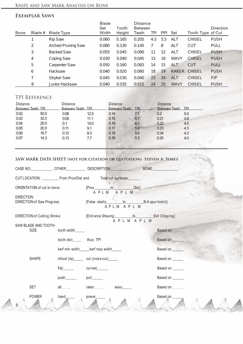
Exemplar Saws
Bone Blade # Blade Type
Blade
Set
Width
Tooth
Height
Distance
Between
Teeth TPI PPI Set Tooth Type
Direction
of Cut
1 Rip Saw 0.060 0.165 0.205 4.5 5.5 ALT CHISEL PUSH
2 Arched Pruning Saw 0.080 0.130 0.140 7 8 ALT CUT PULL
3 Backed Saw 0.055 0.045 0.090 11 12 ALT CHISEL PUSH
4 Coping Saw 0.030 0.040 0.045 15 16 WAVY CHISEL PUSH5 Carpenter Saw 0.050 0.160 0.083 14 15 ALT CUT PULL
6 Hacksaw 0.040 0.020 0.060 18 19 RAKER CHISEL PUSH
7 Stryker Saw 0.045 0.030 0.040 23 24 ALT CHISEL P/P
8 J unior Hacksaw 0.040 0.035 0.015 24 25 WAVY CHISEL PUSH
TPI Reference
SAW MARK DATA SHEET (not for citation or quotation) Steven A. Symes
CASE NO:____________ OTHER:__________ DESCRIPTION:____________ BONE:______________
CUT LOCATION: _________ From Prox/Dist end Total cut sur faces:______
ORIENTATION of cut to bone: [Prox_________to___________Dist ]
A P L M A P L M
DIRECTION
DIRECTION of Saw Progress [False -starts_________to__________B-A spur /notch]
A P L M A P L M
DIRECTION of Cutting Stroke [Entrance Shaving__________to__________Exit Chipp ing]
A P L M A P L M
SAW BLADE AND TOOTH:
SIZE tooth wid th_____ Based on ______
tooth dis t_____ thus TPI Based on ______
kerf min width_____ kerf max width_____ Based on ______
SHAPE chisel (rip)_____ cut (cross-cut )_____ Based on ______
flat______ curved______ Based on ______
push______ pul l______ Based on ______
SET alt_____ raker_____ wavy_____ Based on ______
POWER hand_____ power_____ Based on ______
Distance
Between Teeth TPI
0.02 50.0
0.03 33.3
0.04 25.0
0.05 20.0
0.06 16.7
0.07 14.3
Distance
Between Teeth TPI
0.2 5.0
0.21 4.8
0.22 4.5
0.23 4.3
0.24 4.2
0.25 4.0
Distance
Between Teeth TPI
0.14 7.1
0.15 6.7
0.16 6.3
0.17 5.9
0.18 5.6
0.19 5.3
Distance
Between Teeth TPI
0.08 12.5
0.09 11.1
0.1 10.0
0.11 9.1
0.12 8.3
0.13 7.7

7/28/2019 Symes Saw Hand Out Ni j 2010
http://slidepdf.com/reader/full/symes-saw-hand-out-ni-j-2010 9/12 9
Symes et al., - Mercyhurst College
SAW MARK DATA SHEET (not for citation or quotation) Steven A. Symes
CASE NO:____________ OTHER:__________ DESCRIPTION:____________ BONE:______________
CUT LOCATION: _________ From Prox/Dist end Total cut sur faces:______
ORIENTATION of cut to bone: [Prox_________to___________Dist ]
A P L M A P L M
DIRECTION
DIRECTION of Saw Progress [False -starts_________to__________B-A spur /notch]A P L M A P L M
DIRECTION of Cutting Stroke [Entrance Shaving__________to__________Exit Chipp ing]
A P L M A P L M
SAW BLADE AND TOOTH:
SIZE tooth wid th_____ Based on ______
tooth dis t_____ thus TPI Based on ______
kerf min width_____ kerf max width_____ Based on ______
SHAPE chisel (rip)_____ cut (cross-cut )_____ Based on ______
flat______ curved______ Based on ______
push______ pul l______ Based on ______
SET alt_____ raker_____ wavy_____ Based on ______
POWER hand_____ power_____ Based on ______

7/28/2019 Symes Saw Hand Out Ni j 2010
http://slidepdf.com/reader/full/symes-saw-hand-out-ni-j-2010 10/1210
Knife and Saw Mark Analysis on Bone
SAW MARK DATA SHEET (not for citation or quotation) Steven A. Symes
CASE NO:____________ OTHER:__________ DESCRIPTION:____________ BONE:______________
CUT LOCATION: _________ From Prox/Dist end Total cut sur faces:______
ORIENTATION of cut to bone: [Prox_________to___________Dist ]
A P L M A P L M
DIRECTION
DIRECTION of Saw Progress [False -starts_________to__________B-A spur /notch]A P L M A P L M
DIRECTION of Cutting Stroke [Entrance Shaving__________to__________Exit Chipp ing]
A P L M A P L M
SAW BLADE AND TOOTH:
SIZE tooth wid th_____ Based on ______
tooth dis t_____ thus TPI Based on ______
kerf min width_____ kerf max width_____ Based on ______
SHAPE chisel (rip)_____ cut (cross-cut )_____ Based on ______
flat______ curved______ Based on ______
push______ pul l______ Based on ______
SET alt_____ raker_____ wavy_____ Based on ______
POWER hand_____ power_____ Based on ______

7/28/2019 Symes Saw Hand Out Ni j 2010
http://slidepdf.com/reader/full/symes-saw-hand-out-ni-j-2010 11/12 11
Symes et al., - Mercyhurst College
NOTES:

7/28/2019 Symes Saw Hand Out Ni j 2010
http://slidepdf.com/reader/full/symes-saw-hand-out-ni-j-2010 12/12
Knife and Saw Mark Analysis on Bone
NOTES: