symbiosis 2 001-054 e final · the book “analysis“ by gérald ubassy helpful for determining...
TRANSCRIPT


Content 3
� 7
� 9 11
15 16 17 18 25
27 28 30 30 33 36 38
41 41 44 44 46 46 48 51 52 52 52
� 55 57 59 60 61 64 65
� 67 69 71 72 74 75 75
� 77
Prologue��1�� Analog�vs.�digital�–�A�comparison�of�different�implant-bar�designs
1.1 Patient case I: Analogous implant-bar design (Co-Cr-alloy & galvano) 1.1.1 Trust is good; verification is better! 1.1.2 Cross mounting – Articulation crosswise 1.1.3 Long adhesive bases made of titanium 1.1.4 The journey is the destination 1.1.5 The reward starts with a surprise
1.2 Patient case II: Digital implant-bar design (titanium & galvano-gold) 1.2.1 Well-intentioned yet failing to fulfil its purpose 1.2.2 The first try-in 1.2.3 Predominantly digital, is that the norm? 1.2.4 The future is golden 1.2.5 Complete and ready 1.2.6 Hammer hard
1.3 Patient case III: Complete digital implant-bar construction (zirconium & PEEK) 1.3.1 The design 1.3.2 The aesthetic try-in 1.3.3 CAD/CAM with Zirkonzahn 1.3.4 Only telescopes or what is the answer? 1.3.5 Almost there... 1.3.6 It's all in the set-up 1.3.7 A celebration 1.3.8 The “right” dimension 1.3.9 Finishing 1.3.10 General conclusion
2� A�fir �bite�with�strong�teeth 2.1 Pretzel time 2.2 Trial and error method 2.3 Titanium bar 2.4 Small but effective 2.5 Control freak 2.6 The expectations have been met
3� Cost-effective�Implant�Restoration 3.1 Case description 3.2 Treatment plan 3.3 The ball is round 3.4 Completion 3.5 Conclusion 3.6 Postscript
4� Combination�prosthesis�as�per�Dr.�Paul�Weigl

4 SymbioSiS 2
80 80 81 82 84 85 87 88 93
� 95
97 97 98
98 98
100 100
102 103 105
� 107 109 110 111 114 117
� 119 121 122 123 124 125
� 127 129 129 129 130 130 132 133
4.1 Case description 4.2 Basic principles 4.3 White gold 4.4 Galvano-gold 4.5 Set-up and tertiary construction 4.6 The second prosthesis 4.7 The first goal has been reached 4.8 The completion - as we envisioned 4.9 Conclusion
5� Occlusally�screw-retained�implant�bridge/Procera®�Implant�Bridge�(PIB)��� with�acrylic�veneering
5.1 2008 to the future 5.1.1 Arguments against a fixed restoration with acrylic veneering 5.1.2 Arguments for a fixed restoration with acrylic veneering5.2 Old Scool style
5.3 Patient case I 5.3.1 Preparatory steps 5.3.2 The finished “Old-School-Style” acrylic veneers
5.4 Patient case II 5.4.1 The outer “acrylic layer” 5.4.2 Conclusion
6� Implant-supported�screw-retained�zirconium�crowns�and�bridges� 6.1 Complicated workflow 6.2 An appeal to all implant manufacturers 6.3 The depth of an abutment design 6.4 Occlusally screw-retained zirconium bridge 6.5 Conclusion
7� An�(almost�entirely)�unobtrusive�total�prosthesis�design 7.1 The first impression 7.2 The complete design in detail 7.3 Gingiva colour selection 7.4 The result 7.5 Conclusion
8� Galvanic�structures� 8.1 Galvanic structures – a retrospective 8.2 Orthopantomogram 8.3 Impression and model fabrication 8.4 Attention: Verification needed 8.5 Design I (back to the roots) 8.6 Camper’s plane 8.7 The actual state in situ
Content 5
133 134 137 140 142 143 145 146 147 148 149
� 151 153 153 154 155 156 157 158 159 160 162 163 164
��� � 165
167 168 172 175 176 177
� 183
8.8 Functional balance I 8.9 Design II 8.10 Galvanic structures I 8.11 Titanium inner copings & galvanic structures II 8.12 CoCrMo tertiary construction 8.13 Metal ceramic crowns 8.14 Red-white aesthetic 8.15 Functional balance II 8.16 Final verification 8.17 Showdown 8.18 Conclusion
9� Individual�implant-supported�crown�in�the�premolar�region 9.1 Titanium abutment with zirconium dioxide cap and pressed-on lithium disilicate (e.max ZirPress) 9.2 A short case description and the initial working steps 9.3 Digital design I – titanium abutment 9.4 Back to reality I 9.5 Digital design II – zirconium dioxide cap and anatomical wax crown 9.6 Back to reality II 9.7 Wax work 9.8 Embedding 9.9 The pathfinder 9.10 Painting by numbers 9.11 Ready to go 9.12 Conclusion
10� Aesthetic�veneers�–�conventional�layering�method,��� without�the�CAD/CAM-technique
10.1 Committed to conventional methods 10.2 Alea iacta est 10.3 A gap-free smile 10.4 New game, new chance 10.5 Conclusion 10.6 Result overview
Epilogue

Chapter 1 | Analog vs. digital 11
The following describes various fabrication methods of three similar bar structures. Just to clarify, as expected, the digital bars exhibit a perfect accuracy of fit as well as a passive fit and the materials are of high quality. Why should we even consider another alternative nowadays?
The answer is simple. Any kind of technology, analog or dig-ital, has advantages and disadvantages, which I will illustrate in detail with the help of the following patient cases. Furthermore, I am also addressing dental technicians who are working on bar structures without the use of digital technology who still achieve the same passive fit, functionality, aesthetics and durability. Analog and digital, a direct comparison ... the answer to the question "Which method is better?“ Everyone has to decide for themselves.
1.1�� Patient�Case�I:�� Analogous�Implant-Bar�Design��� (Co-Cr-alloy�&�galvano)
Case�descriptionThe middle-aged patient complained about lack of stability and poor aesthetics of her set of prostheses. Eating and drinking were a true challenge with such unstable prostheses and her wish to regain a better masticatory performance and improve aesthetics was fully understandable (figures 1.1 to 1.4).
After an extensive consultation and thorough examination, we agreed on the insertion of six implants in the maxilla and four implants in the mandible followed by a bar restoration af-ter the average six-month healing period.
During the clinical healing period, we provided the patient with therapeutic, long-term, temporary prostheses produced with the TiF-method (functioning total prostheses), according to total prostheses criteria. This provisional, or rather therapeu-tic phase enables us to verify and correct occlusion, functional-ity, aesthetics and, if needed, soft tissue management.
Prior to this, it is important to perform a situation analysis of the insufficient prostheses. In the next step, we create simple models from the anatomically correct maxilla/mandible im-pressions and mount them with the prostheses and the face bow in the articulator.
The analysis clearly shows the lack of reference to the Camp-er's line. This needs to be addressed, since static compliance is crucial for proper bite function. The upper posterior teeth are almost touching the lower alveolar ridge while the first quad-rant is sagging noticeably causing an unbalanced smile line etc. ... not an overall harmonious appearance. Incidentally, this res-toration was just two years old and “made in Germany“ (figures 1.5 to 1.11).
Figure 1.1 Initial situation, “Made in Germany”, two years old.
Figure 1.2 No matter from which angle, it does not look good.
Figure 1.3 It looks okay but only with the mouth almost closed.
Figure 1.4 Using a cheek retractor to take a closer look.

12 SymbioSiS 2
A thorough consultation with the patient is crucial. I find the book “Analysis“ by Gérald Ubassy helpful for determining the correct shape and shade. It contains beautiful images of nat-ural teeth, illustrating in detail how nature defines itself. Once we agree on a common goal, we select shape and shade. In order to ensure a harmonious colour gradient, I use three different shades of the same colour group for this anterior group of teeth, whereas the central incisors (1) are the lightest, the lateral inci-sors (2) have a slightly different tone and, for the dominant ca-nine (3), we selected the richest shade. I follow this particular sequence based on image analyses from Gérald Ubassy's book and my own observation of natural teeth. This knowledge and experience helps me to improve the natural effect of the restora-tion (figures 1.12 to 1.19). Figures 1.15 to 1.19 illustrate the therapeutic temporary restoration in situ. The set-up was done according to the TiF-method (functioning total prostheses) by Karl-Heinz Körholz.
Figure 1.5 Not much improve-ment on the model.
Figure 1.6 The empty space needs to be filled with teeth, creating aesthetics and functionality.
Figure 1.7 But please, not like this. The upper seventh acrylic tooth almost touches the mandible.
Figure 1.8 The Camper’s line is positioned incorrectly.
Figure 1.9 Close-up. This individual tooth positioning is supposed to simulate natural look, but it rather looks like the unorganized and careless placing of teeth.
Figure 1.10 Right lateral view.
Figure 1.11 Left lateral view. Remarkable: Maxilla/mandible base acrylics display different colours.

Chapter 1 | Analog vs. digital 13
After a successful insertion of the implants and the usual six-month healing period, we were able to remove the healing caps. These elongated healing caps provide a soft lining for the tem-porary restoration, ensuring an even, retentive support (figures 1.20 to 1.23).
Figure 1.12 I am able to show the patient the natural look of anterior teeth with this book
Figure 1.13The mutual agree-ment: Three different tooth shades for the maxilla.
Figure 1.14 Also, the mandible with the Candu-lor-teeth PhysioStar® NFC+.
Figure 1.15The finished the a-peutic temporary prosthesis in situ. Positioning of the teeth and tooth shade are acceptable.
Figure 1.16 But the shade of the prosthesis acrylic is not.
Figure 1.17 Right lateral view.
Figure 1.18Left lateral view. The gentle integration of the acrylic teeth with three different shades.
Figure 1.19The prosthesis base is monochrome; the surface has a subtle anatomical finish.Additional detail will be added to the finished p ostheses.
Figure 1.20 OPG of the inserted implants.

14 SymbioSiS 2
The same healing caps are now screwed into the master model, the temporary restoration is placed on top and the new master model is ready to be mounted in the articulator via face bow transfer.
This approach offers obvious advantages: All previously pre-pared and successfully tested surfaces are suitable for the per-manent restoration, ensuring that the actual available space for each half of the jaw is clearly defined, and we are now ready to work on the bar design. Next, the therapeutic temporary pros-theses are duplicated and the plaster models are mounted in the articulator with the temporary restoration. Significant diver-gences of the implants have to be taken into consideration as well during the design phase. We, therefore, changed our origi-nal one-piece bar design to a two-piece bar design (figures 1.24 to 1.33).
Figure 1.21 By applying a soft lining to the thera-peutic temporary prosthesis, the longer prefabricated healing caps can be used for retention.
Figure 1.22 The soft relining material (Finomoll CR; Fino) was processed in situ.
Figure 1.23 The soft material encases the healing caps, ensuring stabilization.
Figure 1.27 The therapeutic temporary prosthesis, including soft relining, is used for temporary bite registration.
Figure 1.28 The planes are transferrable. Compared to Figure 1.8: Quite a difference and finally a p operly functioning prosthe-sis.
Figure 1.24 Proper function in the mouth means proper function on the model.
Figure 1.25 The divergence of the healing caps does not interfere.
Figure 1.26 The soft material easily glides over it and keeps the prosthesis stable at the same time.

Chapter 1 | Analog vs. digital 15
1.1.1��Trust�is�good;�verificatio �is�better!
Prior to the fabrication of complicated bar designs, it is impor-tant to verify the accuracy of the master models.
I prefer to use the so-called pretzel technique for this step. These fast and easily produced pretzel-shaped metal tools are ideal for efficiently screwing impression posts or insertion aids onto the model analogs, which are then splinted with light cured acrylic. For diverging implants, the tube-in-tube connec-tion needs to be made parallel, otherwise it is impossible to in-sert the pretzel due to the undetermined direction of insertion. The metal pretzels are then tried in situ, enabling easy replacing of certain impression posts in case of model inaccuracy. Any incorrectly positioned post is easily removed and repositioned. The result is a secure fixation thanks to the metal pretzels. The affected model analog is then ground out of the plaster model and reinserted with the metal pretzel. This approach eliminates the need for another impression and a new model (figures 1.34 to 1.37).
Figure 1.32 The divergences are too obvious for a one-piece bar structure.
Figure 1.33 Here, a one-piece bar structure is no problem.
Figure 1.29 The therapeutic temporary prosthesis is ready for duplica-tion. The plaster models are mounted in the articulator.
Figure 1.30 Maxilla master model without gingiva mask. The implant platform is clearly visible.
Figure 1.31 Mandible master model without gingiva mask. The implant platform is clearly visible.
Figure 1.34 Pretzel time.
Figure 1.35The insertion aids, or impression posts, are secured with acrylic. The models in situ are verified y using the pretzel method.

16 SymbioSiS 2
1.1.2��Cross�mounting�–�Articulation�crosswise
I create plaster duplications from the already fabricated tempo-rary restoration and mount these with the original acrylic tem-porary restoration crosswise in the articulator. This guarantees complete control of all surfaces and the three-dimensional space conditions to the opposing jaw, since the duplicated mod-els and the master models are interchangeable. The correct sili-cone indices simplify the verification of the space situation dur-ing the bar construction. It is recommended, and worthwhile the effort, to fabricate the temporary restoration with the same type of artificial teeth (same shade, shape and make) as the per-manent restoration! This extra step is a confirmation that the premolarized set-up method is a success. Aesthetic aspects, phonetics and functionality of the original therapeutic total prostheses/temporary restorations are applied at a 1:1 ratio and need only minor detailed refinement.
I verify the space situation for the anterior and the posterior teeth region with the same set of teeth using different matrices (figures 1.38 to 1.49).
Figure 1.36 It is advisable to keep as much of the antirotational mechanism as possible, allowing a smooth insertion
Figure 1.37 The pretzel unit serves as a precise verification tool
Figure 1.38 Frontal view: The plaster model duplications of the temporary prosthesis.
Figure 1.39 The premolarized set-up is based on the model analysis per the TiF-method (functional total prostheses).
Figure 1.40 Here it is shown adopted 1:1 for the definiti e bar construction.
Figure 1.41 The silicone matrices are created with the temporary prosthesis and the master model in the articulator and are interchangeable.
Figure 1.42 The silicone impres-sions are supported by teeth on one side and by the master model on the other side.

Chapter 1 | Analog vs. digital 17
1.1.3��Long�adhesive�bases�made�of�titanium
Since we had to deal with a tight budget, it was imperative to look for a more cost-effective implant-bar design with a precise tension-free fit. Impossible was my first thought, but the “long“ titanium temporary abutments recommended by Nobel Bio-care solved the problem, since they are significantly longer than the original adhesive bases (see also chapter 6).
These titanium temporary abutments are available with or without an antirotational mechanism. They are commonly used for temporary restorations. Since the design is not anatomical, the cusps in the posterior region are not adequately supported and the durability for single crowns cannot be guaranteed, yet the retentive elongated design facilitates an excellent bonding with veneering acrylics or any other adhesive materials.
The idea: I increase the range of application for a cost-effec-tive, durable bar design by using these accurately fitting titani-um abutments on the implant platform as an adhesive base with an expanded retention zone. Conventional titanium adhesive bases that are used for the bonding of zirconium abutments are too short and lose precious adhesive surfaces during the grind-ing of the direction of insertion, thus resulting in an inadequate outer retentive design, depending on the system. Due to the di-vergences of the implants the titanium adhesive bases need to be ground in the same direction of insertion, thereby facilitat-
Figure 1.43 This facilitates space verification y exchanging the master models with the cast duplications.
Figure 1.44 The mandible master model is placed in the articulator with the cast duplication of the maxilla.
Figure 1.45 The matrix is easily positioned and secured.
Figure 1.46 Cutting back the matrix enables faster verification
Figure 1.47 Focusing on one jaw speeds up the work process.
Figure 1.48 The models are easily exchangeable.
Figure 1.49 Repeated verificationwith the fabricated cast duplicates is mandatory, otherwise the space situation might be misleading.

18 SymbioSiS 2
ing the placing and removing of the future bar. Regular space verification with the acrylic teeth is imperative, since I need ad-equate space for galvano secondary constructions, non high-no-ble alloy tertiary construction, opaquer and liquid acrylic.
The casting material for the bar is an alloy of cobalt-chromi-um-molybdenum alloy. After proper preparation and polish-ing, I use Multilink® Implant adhesive with the bonding agent Monobond Plus by Ivoclar Vivadent to glue the bar to the “new“ adhesive bases (figures 1.50 to 1.55).
1.1.4��The�journey�is�the�destination
For the verification of the definitive expansion of the prosthe-ses, I frequently use different silicone matrices. A correct oral design is especially important since incorrect positioning of the bar inevitably causes an uncorrectable speech impediment. The dimensions are easily verifiable since we used the therapeutic
Figure 1.50 The set-up teeth serve as a good verification tool
Figure 1.51 The “adhesive bases” made of titanium are ground in the direction of insertion.
Figure 1.52 They need to be blocked out prior to starting the acrylic bar modeling.
Figure 1.53 The bar is made of light-cured acrylic and covered with a thin wax layer, thereby preventing fractures in the investment material. Wax melts faster than acrylic in the prewarm furnace, creating a hollow space in the process in which the acrylic fl ws, swells and finally burns
Figure 1.54 The cleaning channels are contoured at this stage.
Figure 1.55 An adequate wall thickness is crucial, since the bar structure will be cemented. This is a disadvantage compared to digitally fabricated bars.

Chapter 1 | Analog vs. digital 19
Figure 1.56 This matrix verifiesthe existing space situation, ensuring proper phonetics.
Figure 1.57 The bar structure has sufficient space onthe lingual side.
Figure 1.58 Thanks to thorough planning, the upper bars also do not interfere with the phonetic.
Figure 1.59 The polished, non high-noble alloy bars display an adequate height, ensuring pro- per friction. A height of six to seven milli- metres would be ideal. The overall height should never be under fi e millimetres.
Figure 1.60 The bar had to be split in two due to the divergence of the implants.
Figure 1.61 The mandibular displays very narrow alveolar ridges, an indication of a premolarized set-up and bar-retained implant work.
temporary restoration repeatedly to ensure that the oral expan-sion was sufficient from a phonetic standpoint. Other dimen-sion verification tools are the duplicated models with the at-tached silicone matrices on which the silicone matrices can be attached. Remarkable: The space between the jaws appears quite large without the matrices in place, yet this space is essential when taking the minimum layer thicknesses into consideration (figures 1.56 to 1.61).
The bars are milled with a zero degree configuration and fur-nished with a Mini-Presso-Matic (by Wegold) in the distal area. These retention elements have a round retention bolt with a steel spring that snaps securely into place. This offers two ad-vantages: In case of an existing friction loss, the retention force is easily restored by screwing the retention bolt into the incor-porated sleeve. The clicking sound of the bolt snapping into place ensures the patient the prostheses are in their definitive position. The silicone matrices with the acrylic teeth are used for the alignment of the Mini-Presso-Matics. The elements are placed between two teeth, thereby avoiding any damage during an exchange of the acrylic teeth in the future. We proceed with the bonding with Multilink Implant once the space situation has been verified. A passive fit is guaranteed since we verified the accuracy of the master models with the pretzel technique during the preliminary stages. Bonding is followed by an effort-less set-up of the teeth with the silicone matrices and the dupli-cated models. At this point, one might be tempted to finalize the fabrication process, but experience has taught me that it is ad-visable to take a closer look in situ particularly in regards to aesthetics. The future colour of the gingiva still needs to be de-termined. The pinkish colour of the wax looks very unnatural and distorts the appearance. We can only truly view the proper
20 SymbioSiS 2
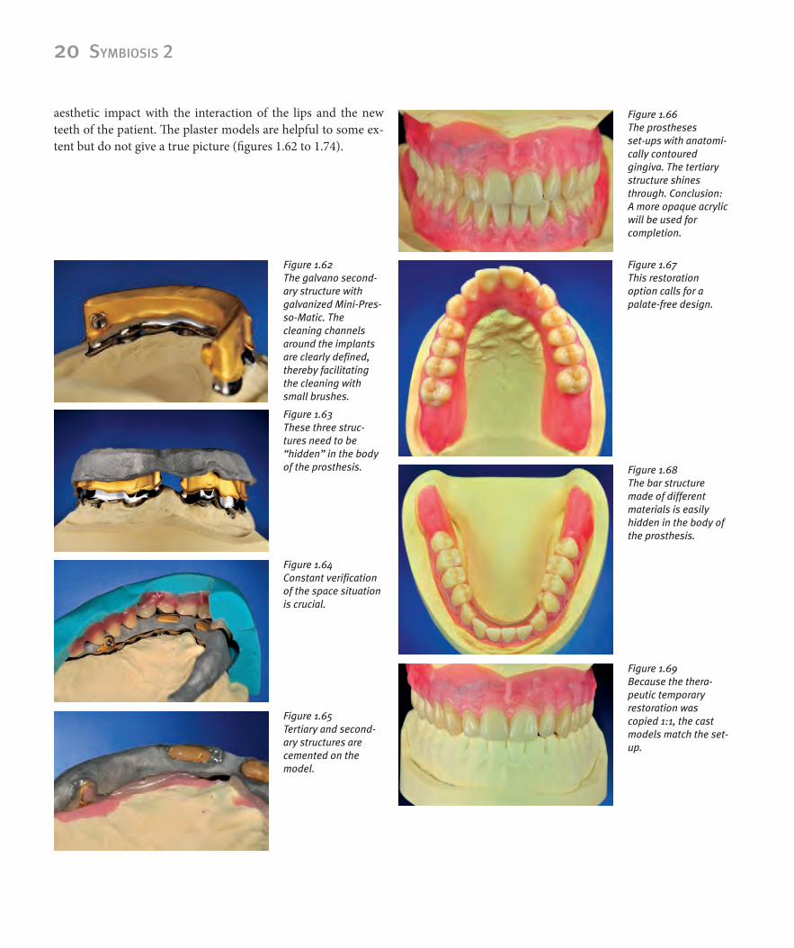
aesthetic impact with the interaction of the lips and the new teeth of the patient. The plaster models are helpful to some ex-tent but do not give a true picture (figures 1.62 to 1.74).
Figure 1.62 The galvano second-ary structure with galvanized Mini-Pres-so-Matic. The cleaning channels around the implants are clearly defined,thereby facilitating the cleaning with small brushes.
Figure 1.63 These three struc-tures need to be “hidden” in the body of the prosthesis.
Figure 1.64 Constant verificationof the space situation is crucial.
Figure 1.65 Tertiary and second-ary structures are cemented on the model.
Figure 1.66 The prostheses set-ups with anatomi-cally contoured gingiva. The tertiary structure shines through. Conclusion: A more opaque acrylic will be used for completion.
Figure 1.67 This restoration option calls for a palate-free design.
Figure 1.68 The bar structure made of different materials is easily hidden in the body of the prosthesis.
Figure 1.69 Because the thera-peutic temporary restoration was copied 1:1, the cast models match the set-up.

Chapter 1 | Analog vs. digital 21
The accurate design enabled us to create a palate-free definitive maxilla prosthesis, therefore achieving a higher wearing com-fort and superior linguistic articulation. The contact surface of the tip of the tongue is preserved, therefore integrating the prosthesis seamlessly into its natural surroundings.
Even the mandible implant-bar construction is easily inte-grated into the prosthesis and barely visible. The oral expansion of the prostheses complies with the therapeutic situation in re-gards to shape and function.
Designing the gingiva always poses a special challenge for me since colour and the shape of the acrylic gingiva have a big impact on the entire restoration. Creating a natural-looking gingiva depends on personal expertise and a skilful colour com-bination. One needs profound knowledge of shape and func-tion in order to recreate tooth shape. Proper detailed gingiva reconstruction, however, is often overlooked and relies on one's very own ideas and experience. Studying and designing the gin-giva and its contour with the alveolar ridges is just as important and time-consuming as studying and mastering tooth design and fabrication. In order to fully understand the various gingiva structures, such as hard and soft tissue, lip and cheek frenulum lines, surface texture (stippling), colour gradient of the gingiva (i.e., from the fixed gingiva to the mucogingival junction) it is imperative to thoroughly study images of natural gingiva. Fab-ricated prostheses are motivating, but they are only a copy of nature. Some are skillfully crafted; others are less promising. Just by looking at these prostheses, I notice certain details that I overlooked at the time of fabrication and that I would imple-ment differently today.
It is important to create a slightly uneven line since no pa-tient has perfectly symmetrical teeth or gingiva.
For colouring the gingiva, we have different techniques to choose from (figures 1.201 and 1.202): Applying different tinted powder/liquid mixtures to the matrix followed by either the use of the press/plug or flow technique with the basic acrylic (hot or cold polymer). I chose a different method and achieved great results by filling the matrix with prosthesis acrylic and allowing it to polymerize (cold polymer), then reduce the areas and rede-sign them with Gradia Gum by GC. This allows me to instantly verify the colour effect.
Figure 1.70 All details were also copied and integrat-ed.
Figure 1.71 The first t y-in: The pink set-up wax looks out of place.
Figure 1.72 Selecting the shade of the gingiva.
Figure 1.73 Subtle overlapping details enhance the natural appearance.
Figure 1.74 But they always need to be approved by the patient.

22 SymbioSiS 2
Prior to applying the Gradia Gum compounds the acrylic is pretreated with bonding material enabling us to enhance with colours or to cover critical areas where metal frameworks with opaquer shimmer through. The colour design is, therefore, pre-cisely evaluated and easily modified.
Next, I have to hide the palatinal prosthesis edge. I fill the etched area of the rim with transparent acrylic (PMMA) antici-pating the same chameleon-effect as with layered ceramic ve-neers. The images in situ will reveal later on if the effort was worth it (figures 1.75 to 1.88).
Figure 1.75 The finished maxillaprosthesis.
Figure 1.76 The finished mandi -ular prosthesis. The dorsal region has been patient-specificshortened after the wax try-in.
Figure 1.77 The alveoli mounds display a convex shape in the root area while they are concave- shaped between the teeth. Anatomical contouring of the pala- tal area has been com- pleted.
Figure 1.78 A slightly irregular design enhances the natural appearance.
Figure 1.79 Subtle surface textures are more natural than overdone efforts to imitate the natural stippling of the gingiva.
Figure 1.80 Tooth 32 is slightly longer with an irregular gingiva margin. Such natural “imperfections” enhance the desired true-to-nature look.
Figure 1.82 The tertiary structure no longer shows through despite the thin acrylic wall.
Figure 1.81 Everything is neatly polished and displays a beautiful shine.

Kapitel 1 | Analog vs. digital 23
Neat transitions intra the prostheses are crucial. It simplifies the cleaning process for the patient since undercuts are eliminated. The bar seals everything perfectly (figures 1.89 to 1.95).
Figure 1.83 Gingiva and teeth show a harmonious overall appearance.
Figure 1.84 The clever chameleon effect is used for the prosthesis margin on the palatal side.
Figure 1.85 Etching the padding area of the palate seals the edge properly.
Figure 1.86 This prevents uncomfortable tongue interference.
Figure 1.87 A high-quality total restoration should be unobtrusive and have a subtle appearance.
Figure 1.88 Accurate anatomic structures are important for the patient.
Figure 1.90Neat transitions facilitate cleaning for the patient
Figure 1.89 Detailed view of the galvanized Mini-Pres-so-Matic without retaining pin.
24 SymbioSiS 2
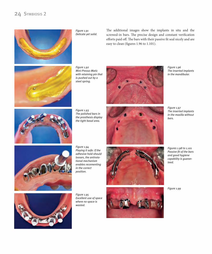
The additional images show the implants in situ and the screwed-in bars. The precise design and constant verification efforts paid off. The bars with their passive fit seal nicely and are easy to clean (figures 1.96 to 1.101).
Figure 1.96 The inserted implants in the mandibular.
Figure 1.97 The inserted implants in the maxilla without bars.
Figures 1.98 to 1.101 Passive fit of the barsand good hygiene capability is guaran-teed.
Figure 1.99
Figure 1.91 Delicate yet solid.
Figure 1.92 Mini-Presso-Matic with retaining pin that is pushed out by a steel spring.
Figure 1.93 The polished bars in the prosthesis display the tight basal area.
Figure 1.94 Playing it safe: If the adhesive hold should loosen, the antirota-tional mechanism enables recementing in the correct position.
Figure 1.95 Excellent use of space where no space is wasted.

Kapitel 1 | Analog vs. digital 25
1.1.5��The�reward�starts�with�a�surprise
The figures 1.102 to 1.107 show the inserted prostheses. Colour, shape and function turned out as planned...really? I was satis-fied with my work and anticipated a bright happy smile from “my patient.“ Unfortunately, she no longer liked the look of her anterior teeth.
After analysing the situation and another consultation ses-sion, we agreed to redesign the gingiva in region 12 to 22.
Reducing the gingival sections at the neck of the tooth of the acrylic teeth caused a rather rectangular shape instead of the usual square shape.
A direct comparison (figures 1.108) revealed the remarkable effect the gingiva has on the tooth shape: Same teeth different effect!
The redesign and modification efforts were a success. The patient regained her beautiful smile and I learned a lot about the effect artificial gingiva has on a restoration (figures 1.108 to 1.112).
Figure 1.100
Figure 1.101
Figure 1.104 The finished p osthe-ses in situ.
Figure 1.106 Left lateral view with cheek retractor.
Figure 1.105 Right lateral view with cheek retractor.
Figure 1.102 The chameleon effect looks almost perfect.
Figure 1.103 However, the colour does not quite match in the dorsal region. Fortunately, the patient does not mind.

26 SymbioSiS 2
Figure 1.107 An unpleasant surprise: The patient thinks the teeth are too small!
Figure 1.108 The gingiva has been modified, the teethare the same! Before and after.
Figure 1.109 The patient is content.
Figure 1.110 learned a lot about the importance of the gingiva.
Figure 1.111 Final photo with a beautiful smile.
Figure 1.112