sylvania engineering bulletin - germicidal & short wave uv
TRANSCRIPT

8/3/2019 Sylvania Engineering Bulletin - Germicidal & Short Wave UV
http://slidepdf.com/reader/full/sylvania-engineering-bulletin-germicidal-short-wave-uv 1/16
Sylvania Engineering
8uIIetin 0-3420981
INFRARED
X RAYS---1
SCHUMANN
100
..j.UV'B.j. UV- AV-C
400
~XTREMEU~
280 315
FA R U V ~ MIDDLE UV+ NEAR UV . 1
10 100 200 300 380
WAV EL EN G TH (N A NOM ET ER S)
ELECTROMAGNETIC SPECTRUM(enlaroement of ullroviolel reqionl
Figure 1
Germicidal and Short-WaveUltraviolet Radiation
layer of the upper atmosphere.
Although the percentage of ultraviolet
energy in sunlight is small, there is still
appreciable energy in the shorter wave-
lengths. The germicidal effectiveness of
sun l ight varies enormously with the
hou r of the day and also with the sea-
sons. Germicidal lamps, however, make
ultraviolet energy available with con-
trollable limits regardless of natural
environmental conditions.
Radiant energy from the sun may be
divided into th ree broad bands: 10ng-
wave or infrared energy such as heat,
which is invisible; visible energy which
produces light and color; and short-
wave energy such as invisible ultravio-
let. As shown in Figure 1, it is the
ultraviolet radiation between 220 and
300 nanometers that is germicidal in
effect; i.e., it destroys bacteria, mold,
yeast, and virus. Practically none ofthe
solar ultraviolet energy below 295
nanometers can reach the earth's sur-
face due to absorption in the ozone
Germicidal Lamps
Germicida I lamps are electrically the
same as fluorescent lamps of corre-
sponding sizes and wattages and
PREFACE
The information presented in this
bulletin is based on research and data
available at the time of publication.
It is, however, beyo nd the scope of this
bulletin to review the entire field of
ultraviolet radiation. Only basic dataand current application concepts will be
discussed.
The end user should always consult
current l iterature for proven application
data on ultraviolet radiation. It is essen-
ti a l t hat the end ussr shoul d read the
precaution notices on the proper appli-
cation of the ultraviolet lamps to insure
adequate safety .
require essentially the same auxi I iary
equipment. These lamps differ phys-
ical Iy from fluorescent Iamps in that
they contain no phosphor and are con-
structed with a special type of glass to
permit maximum emission of germici-
dal ultraviolet energy. The glass used in
ordinary fluorescent lamps filters out
all germicidal ultraviolet energy. The
physical and electr ical characterist ics of
the germicidal lamps are shown in
Table I.
The most practical method of gene rat-
ing germicidal radiation is by passage
of an electric discharge through a low-
pressure mercury vapor. About95% of
the ultraviolet energy is radiated in the
253.7 nanometer line. This is in the
wavelength region of greatest germici-
dal efficacy. Typical spectral power
distri buti on for the tu bul ar germicida I
lamps, showing the principal radiat ion,
is illustrated in Figure 2.

8/3/2019 Sylvania Engineering Bulletin - Germicidal & Short Wave UV
http://slidepdf.com/reader/full/sylvania-engineering-bulletin-germicidal-short-wave-uv 2/16
PRIN cIP AL RAD IAT IO N O F TH E G 3O T8 G ERM 'IC ID AL LAM P
IOOr---_,----~----_r----,_----~----~----r_--~r_--_,----~
t i l l : l : l : ~ 2~3_7
~'UI ""... ~ ~ !f46.1 5710O~~~ __ ~--==~_~~m_~~~U~~·····~··'·'LL_ ~ ~·~"~"L·=-~220 260 300 340 390 420 460 500 540 580
WAVELENGTH -NANOMETERS
Figure 2. The mercury line at 253.7 nm accounts for approximately 9()% of the energy
radiated in the 250·600 nm region. The G1Sra and GaTS Germicidal lamps have spectral
power distributions similar to the graph shown.
TABLE I.GERMICIDAL LAMP DATA'
Description G8T5 G15TS G30TS
Rated Power (watts) 8 15 30
Bulb T5 T8 T8
Base Min. Bipin Med. Bipin Med. Bipin
Nominal Lamp Length (inches) 12 18 36
Ncminal-Arc length (inches) 8'12 1'4 32
Rated life (hours) 7500 7500 7500
253.7 nm Output (watts)3 1.4 3.3 8.2
253.7 nm Power Density at One Meter 15 35 80(microwatt per cm')'·3
Approximate Lamp Amperes 0.15 0.30 0.35
Approximate Lamp Volts 57 56 100
1. The life and radiant power of these
lamps are based on operation with bal-
lasts providing the proper operating
characteristics.
The majority of germicidal lamps oper-
ate most efficiently in still air at anambi ent temperatu re of 77°F.These are
the conditions under wh ich the uItravi 0-
let output is measured and tabulated.
The ultraviolet output, and conse-
quentlythe germicidal effectiveness of
these lam ps decreases at tem peratu res
above or below this optimum tempera-
ture. Lamps operating in a room at 40cF
produce only about two-thirds to three-
fourths as much ultraviolet power as at
2. On line perpendicular to lamp axis
through lamp center.
3. 100 hour value.
77°F. If a lamp is cooled by air currents
or by submersion in a liquid, the ultra-violet output similarly decreases. Typi-
cal maintenance of germicidal lamp
types is shown in Fig. 3. While mainte-
nance is a di rect fu nction of bu rn ing
hours, dust collecting on the tube and
reflecting surfaces can easily double
the loss as determined at the irradiated
surface.
100
o 60
"
o 4 5
THOUSANDS Of HOURS BURNED
Figure 3. Typical maintenance charac-
teristics for germicidallemps.
Sylvania Germicidal Lamps
620
Sylvania germicidallemps are available
in three wattages.
A complete description of all three
lamp types is included in Table I. The 8,
15, and 30 watt sizes are designed to
operate with standard fluorescent lampequ ipment of correspo ndi ng size.
Need for Germicidal Lamps
"Fresh air" always has been considered
beneficial. Indoors, however, the air can
be relatively stagnant or have poor cir-
culation, particularly during cold
weather. Also, it can be contaminated
with germs from human beings. Under
such conditions, ai r can be a means
of carrying infectious organisms into
the body.
Bacteria and mold spores in the air can
cause considerable damage to prod-
ucts in a wide variety of industries. This
damage takes the form of spoilage and
contamination. In addition to the costs
resulting from such damage, there are
costs of added maintenance and refrig-
erati on, plus th e ever-present threat to
the health of consumers of the affected
products. Product sanitation obviously
is of vital importance.
Safety Precautions
Itis essential that adequate precautions
be taken in any application of germici·
dallamps. Prolonged exposures to high
intensities of ultraviolet radiation can
cause temporary; but painful inf lamma-
tion ofthe conjunctiva (inflammation of
the outer membrane of the eye), as well
as histological effects in the cornea, iris,
•

8/3/2019 Sylvania Engineering Bulletin - Germicidal & Short Wave UV
http://slidepdf.com/reader/full/sylvania-engineering-bulletin-germicidal-short-wave-uv 3/16
and lens of the eye. In extreme cases,
permanent harmful effects can occur.
Reddening or even burning of the skin
(erythema), similar to sunburn, will be
caused by excessive exposu re to uI tra-
violet energy.
The glass used in conventional eye-
glasses affords adequate eye protec-
tion fo r brief exposu reoHowever, care
should be taken that the ultraviolet
energy does not enter the eyes from
the side, nor is reflected into the eyes
from the back side ofthe glasses.
Clear plast ic face shields are available
to protect the face. Welder's shields
sometimes have been used. Such pro-
tection should include the ears, par-
ticularly when the wearer may be
exposed to a number of lam ps, It is well
to remember that when one is exposed
to short-wave ultraviolet energy; the
effects may not be felt until several
hours afterward. Likewise, individualsvary greatly in their sensitivity to radia-
tion. Children, for example, are fre-
quently more sensitive to ultraviolet
than are adults.
Where the conce ntration of germi cidal
energy is especially high, protection of
hands and arms may be necessary.
Clothing and gloves will generally pro-
vide adequate protection.
Safe exposure l imits for ultraviolet ger-
micidal irradiation have been set by the
American Conference of Governmental
and Industrial Hygienists."
The general practice based on these
limits is given in Table II. Exposure is
roughly the product of irradiat ion
(microwatts per square centi meter) and
time. The safe exposure time at 2% feet
from a bare G30TB germicidal lamp is
about one minute based upon this
practice.
Table II. Recommended maximum safeexposure to Germicidal Ultraviolet"
Exposure
P er D a v8Hours4 Hours1 Hour10Minutes1 Minute
Irradianee J.l.W em-'0...2
0. 4
1. 6
10
10 0
"Based onthe 253.7nm radiation of thegermicidal lamps.
The near ultraviolet region ofthe spec"
trum in the vicinity of 330 to 380
nanometers is used for "black light"
effects. This radiat ion does not produce
erythemal effects. Note that there are
extreme exposure limits on all parts of
the Ultraviolet, visible, and infrared
regions of the spectrum. (See Refer~
ence 13 for a discussion of exposure
limits).
Exposure Time
A lethal exposure period of an organ-
ism is determined by its susceptibili ty,
the wavelength of radiation, the density
of the radiant flux (watts per unit area),
and the time exposure. Table I I I gives
the amount of 253.7 nm energy density
in microwatt-seconds per square cen-
t imeter to destroy 90 percent of va rious
common microorganisms.
The germicidal effect iveness is pro-
portional to the product of intensity
times time from one microsecond to a
few hours.
TABLE III. GERMICIDAL ENERGY
REQUIRED TO DESTROY COMMON MICROORGANISMS
Organisms
BacilIusanthracis
S. enteritidis
B. megatheriumsp. (veg.)
B. megatheriumso. (spores]
B. paratyphosusB. subtilis
B. subtilis spores
Corynebacteriumdiphtheriae
Ebenhella tvphosa
Escherichia coli
Micrococcuscandidus
Micrococcussphaeroides
Neisseriacatarrhalis
Phytomonastumefaciens
Proteusvulgaris
Pseudomonasaeruqlnosa
Pseudomonasfuorescens
S. typhimurium
Sarcinalutea
Ssratia marcescens
Dysentery bacl I I i
Shigellaparedvsenteriae
Spirillum rubrum
Staphvlococcus albus
Staphvloccccus aureus
Streptococcus hemeIytlcus
Streptococcus lact is
Streptococcusviridans
YeastSaccharomycesellipsoideus
Saccharomycessp.
Saccharomycescerevisiae
Brewers'yeast
Bakers' yeast
Common yeastcake
Mold Spores
Penicillium roquetorti
Penicillium expansum
Penicillium digitatum
Aspergillusglaucu5
Aspergillusflavus
Aspergillusniger
Rhizopus nigricans
Mucor racemosusA
Mucor racemosusB
Oosporalactis
3
Green
Olive
Olive
Btuishgreen
Yellowish green
Black
Black
White gray
White gray
White
Energy
(I'w'S8C/cm2)
4520
4000
1300
2730
3200
7100
12000
3370
2140
3000
6050
10000
4400
4400
2640
5500
3500
8000
19700
2420
2200
1680
4400
1840
2600
2160
6150
2000
6000
8000
6000
3300
3900
6000
Color
13000
13000
44000
44000
60000
132000
111000
17000
17000
5000

8/3/2019 Sylvania Engineering Bulletin - Germicidal & Short Wave UV
http://slidepdf.com/reader/full/sylvania-engineering-bulletin-germicidal-short-wave-uv 4/16
Measurement of UltravioletRadiation
An ultraviolet meter developed by
Ultra-Violet Products, Inc., measures
253.7 nm germicidal radiat ion direct ly.
Visible light is not measured with this
meter. Measurements are calibrated in
microwatts per square centimeter
(p.Wlcm2). Figures 4A and 48 illustrate
the meter. International Light, Inc., also
manufactures and markets instruments
that measure the germicidal region of
the spectrum (see Fig. C.) . As lamps
age, it is important to know when to
replace lamps that have fallen below
the standards normally required for
effective germicidal action. Since it is
impossible to observe when this point
occurs by looking at the tube, the use of
a meter becomes imperative.
Figure 4A. TheBlAK-RAY~ UltravioletMeter is calibrated to measure short waveintensity in microwarts per squarecentimeter.
Applications
The more common applications of
germicidal lamps fall into two broad
classifications, personal protection andproduct protection. Personal protection
is the irradiation of the air in a room for
the purpose of protecting the occu-
pants from airborne infectious dis-
eases. Product protection isthe use of
ultraviolet radiation in areas where
food, pharmaceuticals. and other prod-
ucts are processed and stored to pre-
vent contamination and spoilage by
molds or other microorganisms.
Figure 48. Detachable sensor cell makes readings asclose as a one-quarter inch fromthe irradiated surface. The picture shows the measurement of short wave radiation onsubstances in laboratory dishes.
Figure 4C . The IL570 Germicidal/Erythemal Radiometer is an instrument specificallydesigned for measurements in the ultraviolet portion of the spectrum.
Air Irradiation in Heating and Air-
Conditioning Ducts: Germicidal lamps
are used in heating and air-conditioning
du cts to reduce the qua ntity of live bac-
teria and to make the air passing
through the ducts equivalent. insofar as
possible, to outdoor air in terms of free-
dom from live bacteria. The design of
any system for air steri lizat ion depends
upon the sou rces of the conta mination.
the type of space, and the kind of occu-
pancy of the space. The requirements
fortheaters, restaurants, and stores are
quite different from those for sch 001s
4
•
•
•

8/3/2019 Sylvania Engineering Bulletin - Germicidal & Short Wave UV
http://slidepdf.com/reader/full/sylvania-engineering-bulletin-germicidal-short-wave-uv 5/16
and those for hospital wards and oper-
ating rooms.
Ai'r being brought into a room or build-
ing can be sterilized readily by properly
placing lamps in the air-handling duct
work. The size and shape of the duct,
the ultraviolet reflection characteristics
of walls, and the number and arrange-
ment of the lam ps determ ine the effi-ciency. The essential featu re of the
geometry is to insure that all the baete-
rta passing through the duct are sub-
jected to sufficient bactericidal
irradiation.
A simpl ified formul a for caIculati ng the
number of G30T8 germicidal lamps in
such ducts for air temperatures of
6 5 D-70°Fis as follows:
N = CFM. where20xd
N =approximate number of G30T8
lamps required
CFM = cubic feet of air per minute
d =smaller cross-sectional
dimension of duct in inches
More accurate calculations which may
be required for large installations
require an allowance for air tempera-
ture and humidity. Fora relative humid-
ity of 60% or less, if the duct a Ir
temperature is less than:
60°F - increase the number of lamps
1% times.
50°F- increase the number of lamps2% times,
40°F - increase the number of lamps
4times, and
30°F - increase the number of lamps
6 times.
At higher relative humidities, twice this
number of lamps should be used.
The basis of th is form ula is a 90% deac-
tivati on of the standa rd test micro-
organism. Eschericia coli. It is assumed
that the duct walls have zero reflectance
to 253.7 nanometer energy.
Example
How many G30T81amps would be
required for 10,800 CFM of air carried
by a 60- by 75-inch duct?
Air temperature is 60°F,relative humid-
ity 55%.
N = 10,800 1V :20 x 60 x z
N = 13..5or 14 lamps
AI,though there are a number of ways of
installing germicidal lamps in air ducts,
the best compromise is to place the
lamps lengthwise on the duct wall. The
lamps should be mounted on4-to &-
inch centers. and grouped in the center-
half of the duct walls, away from the
corners (rectanqutar ducts). Where
mechanical conditions require it, the
lamps may be mounted end-to-end
alonq the duct. Several methods of
installing germi.cidallamps in air ducts
are shown in Figures 5A, B, and C.
TYPICAL METHODS OF INSTALLING GERMICIDAL LAMPS IN AIR DUCTS
//
Figure5A.
Since germicidal lamps must be kept
reasonably free of dust for best results,
they must be accessible for cleaning.
This requirement can usually be met by
the use of hinged panels on the sides or
the bottom of the ai r duct
In large ducts, germicidal lamps may be
assembled in vertical frames,like rungs
of a ladder, supported in the center of
the chamber in whatever series or mul-
tiple arrangement bestfits local condi-
tions and also provides access for
cleaning and replacement.
Figure5B.
In very large ducts where the ai r speeds
are relatively low, the tubes should be
placed in such a man ner that the aver-
age distance measured perpendicular
from the tubes to the duct walls is max-
imum. The direction of airflow is not
considered in this situation.
It is sometimes desirable to combine
the germicidal treatment of ai r with
humidifying, filtering, and heating. In
such cases, if possi ble, the lam ps
should be placed at a point of average
air tern peratu re, away from th e very hot
5
12'
FigureSC.
air ar the very cold air .Further, th e
lamps shou Id be placed after the air fil-
tering,. but before the humidificati on
stage of the system. Placl ng the lamps
after filtering reduces lamp mainte-
nance; placing them before humidifica-
tion increases germicidal effectiveness,
since humidification tends to increase
the resistance of bacteria and other
microorgan isms to germ icida I energy.
Irradiation of Air and Room Surfaces:
Wa,rm alr in hospital rooms, offices,
school rooms, cafeterias, and hallways

8/3/2019 Sylvania Engineering Bulletin - Germicidal & Short Wave UV
http://slidepdf.com/reader/full/sylvania-engineering-bulletin-germicidal-short-wave-uv 6/16
normally rises toward the ceil ing. The
convecti on cu rrents force cooler air
down along the walls to the floor where
the air is warmed and again rises. The
presence of such heat sources as radia-
tors, floor lamps. and even human
beings generally aids in the convection
of air.
Due to this air movement in a room,
germicidal lamps can be installed on
walls, slightly above eye level, and still
be germicidally effective. Air irradiated
near the ceiling is caried by convection
to the lower portions of the room with-
out exposing human occupants to
direct lamp radiation. The effect is simi-
la r to excha nging the air in the room
with air from the outside.
Germicidal fixtures may be either
recessed in the wall or surface-
mou nted on the wa II. These two meth-
ods are illustrated in Figures 6 and 7.
Two types of fixtu res may be used gen-
erally in occupied rooms: open and
louvered types. Diag rams of these two
types are shown in Fig ures 8 and 9.
INSTALLATION OF GERMICfDAL FIXTURES FOR AIR AND ROOM SURFACES IRRADIATION
Figure 6. Recessed in the wall. Figure 7. Surface-mounted on the wall.
TYPES OF FIXTURES USED IN OCCUPIED ROOMS (TYPICAL PLACEMENT)
12ft.
Figure 8. Open fixture.
The open type fixture is satisfactory for
rooms where the ceiling is at least 91;l
feet in heig ht and where the oceu pants
do not stay fo r more than eight hou rs at
a time. Where ceilings are less than 9%feet high and where the occupants
remain for prolonged periods as in hos-
pital wards and nurseries, the fixtures
should be louvered.
Any plan to install germicidal lamps
for upper-a ir i rradiati on must take into
account the ultraviolet reflectance
characteristics of the ceiling. In areas
with painted "white-coated" plaster
7ft.9ft.
6%ft.
Agure 9. Louvered fixture.
6
TABLE IV.
Recommended Number of 15- or 30-
Watt Germicidal Lamps For Irradiation
of Upper Air In Rooms IOpen-front or
Louvered Fixtures)
Room WIdth_III.)
1~13 14-18 19-24 211-3132·31
Room
L.. gth "'mp SIze1Ft. ' 15W lOW 1SW :;oW 15W lOW 30W 30W
10-13 2 1
14-1,8 2 1 3 1
19-24 2 1 3 1 4 2
25·31 3 1 4 2 5 2 3
32·39 5 2 3 3 4 5
40-48-3 3 456
49-58-4 4 567
ceilings and walls, an exposure of more
than two to three hours may be unsafe
unless proper finishes are used. The
"white-coat" should be painted with
either a water-solubte or an oil peint,
The number of lamps recommended in
open-front or in louvered fixtures for
the irradiation ofthe upper air is given
in Table IV.This data is based on 90%
upper-air deactivation of a standard
microorganism, Eschericia coli. An
annual fixture cleaning and lamp
replacement is assumed.

8/3/2019 Sylvania Engineering Bulletin - Germicidal & Short Wave UV
http://slidepdf.com/reader/full/sylvania-engineering-bulletin-germicidal-short-wave-uv 7/16
Product Protection
Although germicidal radiation was dis-
covered 150 years ago, it developed
from a laboratory curio to an engineer-
ing tool on'ly during the last quarter of
a century.
Germicidal applications for product
protection are numerous. They rangefrom the simple application of germici-
dal energy on products stored in
storage cabinets to the i rradiati on of
harmful organisms in liquids. New
fields for the use of germrcidallamps
exist wherever products designed for
huma n co nsu motion are ma nutac-
tured, or wherever a health hazard
exists due to bacterial conta rni natl on.
All reflectors for industrial applications
of germicidal lamps should provide
60% to 70% reflectance for energy at
253.7 nanometers ..Materials should be
of highly polished metal surfaces such
as stainless steel, polished Alzak alumi-
num, decorative chrome plate, or
l.uriurn". All fixture parts should be
specially processed for resista nce to
acid or alkal ine fumas and m oistu re
(See Figure 10). Figure 11 i llustrates a
simple fixture that can be used to pro-
vide direct germicidal irradiation. The
relative radiant intensity is shown on a
polar graph.
Airborne microorganisms such as bac-
teria, yeast, and mold spores, cannot
thrive onthe surfaces of foods, l iquids,
and pharmaceuticals if these surfaces
are direct ly irradiated with sufficient
amounts of ultraviolet energy. Mold
spores,i n general, are more resista nt to
ultraviolet energy than airborne bacte-
ria. Hence, high intensities ofgermici,
dal energy are requ ired for good
control. If mold has already formed,
ultraviolet energy cannot eliminate it.
The food indu stry represents awide
and varied field of application ..Non-
food products also offer a considerable
number of applications.
List of Products Protected by Germici-
dal Lamps:
Food Products
Sugar: granulated, syrups
Beverages: fru it ju ices, bottl ed dri nks,
beer, wine
Dairy Products: milk, cheese
Baked Goods: bread, cakes
Fruit
Nuts, Pies, Pickles
Vinegar
Veg.etables
Water
Meats: processing, packaging, storing
(coolers)
Non-Food ProductsBiologicals: vaccines, serums, tox-
aids, ointments
Packaging
Instruments: medical, dental, barber
equipment
Textiles
Bottling Operations
Storage Cabinets
Paper Products
Industrial Liquids: oils, dyes
Glasses.
Toothbrushes
Figure 10. Fixtures for germicidal lampsshould be of highly polished surfaces, andresistant to acid or alkaline fumes andmoisture.
A LZAK AL UM I "! UM 'RE FLECTOR A"!O T - 8 LAMP
1~L5·'-
R ADIA NT IN TE NS ITY - % O F BARE LA MP
RADIANT I"!TENSITY - 'f. OF ,BARE LAMP
PII,RALL:EL 0- PER PENDIC ULAF!TO LAMP TO LAM P
Figure 11. This illustrates atypical distribu-tion curve of a bare T -B germicidal lamp inan Alzak aluminum reflector.
Ultraviolet Sanitation
There are three general methods for
ultraviolet sanitation thet can be used,
either separately or in combi nati on:
7
1. Upper-air Irradiat i on:
This helps to provide an area.o f irra-
diated air in the upper portion of the
roo m. Normal ai r currents diIute the
lower contaminated air with the
purified air to maintain a low bacte-
rial count at the breathing level.
Upper-air irradiation permits contin-
uous, safe occupancy of a room (See
Figure 1 '2) .
2. Barrier- Type Irradiati on:
This type of germicidal installat ion
provides a narrow beam of germici-
da I energy that ca n be di rected to
prevent the passage of live micro-
organisms from one place to
another. This method is illustrated
in Figure 13.
3. Direct Irradiation:
This is the most efficient way of dis-
infecting', not only the air of a room,
but also the exposed solid surfaces.
The Iimitation of this method is that
germicidal intensities are also irr itat-
ing to the skin and eyes of both
individuals and animals in the room.
It is necessa ry to tu rn the germicidal
lam ps off when workers a'Fean rou-
tine duty or to protect them by
goggles, masks, gloves, or other
means. Germicidallamps are used
for the di rect irradi ation of va rious
biological l iquids, such asserums,
plasma, vaccines, toxins, etc.
figure 12. The principle of upper-air irra-diation is shown in a veterinary hospital.Upper air in the zone lrradlated by germici-dalIampsls disinfected and displaceddownward, diluting microorganism con-centration at the lower level.
8/3/2019 Sylvania Engineering Bulletin - Germicidal & Short Wave UV
http://slidepdf.com/reader/full/sylvania-engineering-bulletin-germicidal-short-wave-uv 8/16
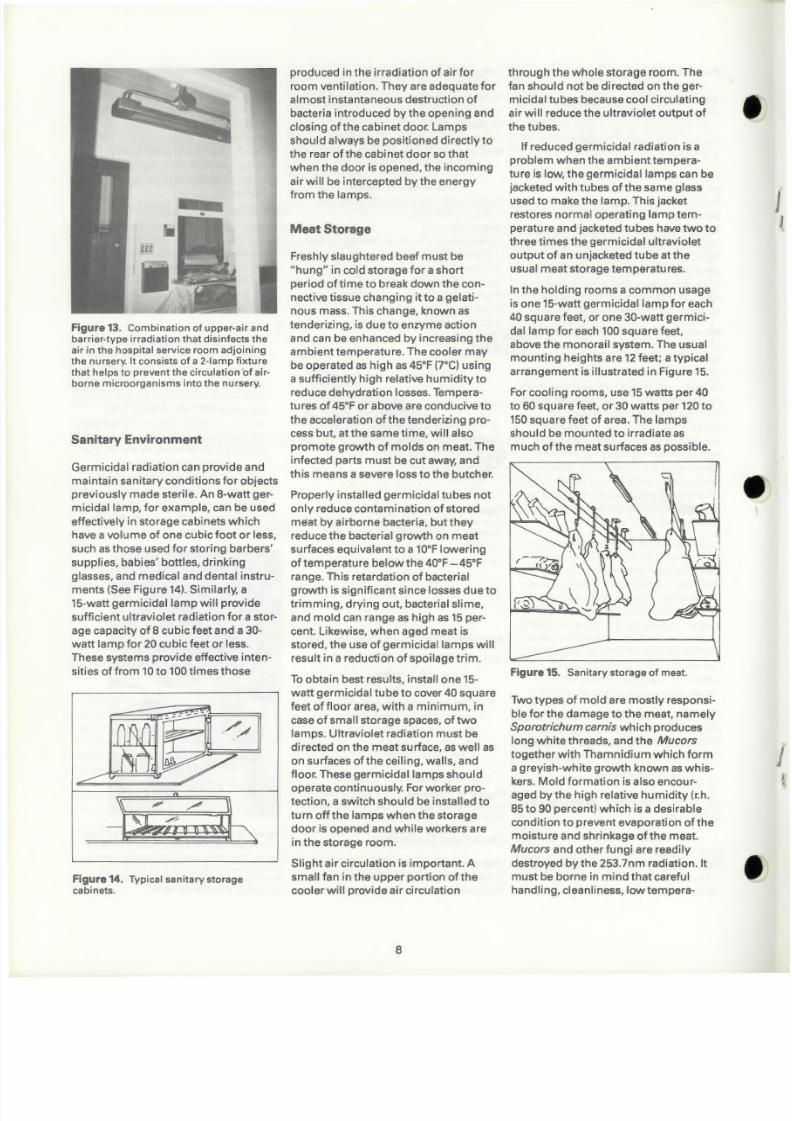
Figure 13. Combination of upper-air andbarrier-type irradiation that disinfects theair in the hospital service room adjoiningth e nurserv It consists of a 2-lamp fixtu rethat helps to prevent the circulation 'of air-borne microorganisms into the nursery.
Sanitary Environment
Germicidal radiation can provide and
maintain sanitary condit ions for objects
previously made sterile. An 8-watt ger-
micidal lamp, for example, can be used
effect ively in storage cabinets which
have a volume of one cubic foot or less,
such as those used for storing barbers'
supplies, babies' bottles, drinking
glasses, and medical and dental instru-
ments (See Figure 14). Similarly, a
15-watt germicidal lamp will provide
sufficient ultraviolet radiation for a stor-
age capacity of 8 cubic feet and a30-
watt lamp for 20 cubic feet or less.
These systems provide effective inten-
sities of from 10to 100 times those
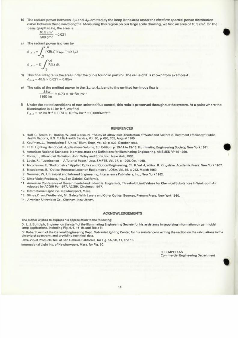
Figure 14. Typical sanitary storagecabinets.
produced in the irradiation of air for
room ventilation. They are adequate for
almost instantaneous destruction of
bacteria introduced by the opening and
closing of the cabinet door. Lamps
should always be positioned directly to
the rear of the cabi net door so that
when the door is opened, the incoming
air will be intercepted by the energy
from the lamps.
Meat Storage
Freshly slaughtered beef must be
"hung" in cold storage for a short
period of time to break down the con-
nect ive tissue changing it to a gelati-
nous mass. This change, known as
tenderiz ing, is due to enzyme act ion
and can be enhanced by increasing the
ambient temperature. The cooler may
be operated as high as 45°F pOe) using
a sufficiently high relative humidity toreduce dehydration losses. Tempera-
tu res of 45°F ar above are conducive to
the acceleration of the tenderizing pro-
cess but, at the same time, will also
promote growth of molds on meat. The
infected parts must be cut away, and
this means a severe loss to the butcher.
Properly installed germicidal tubes not
only reduce contamination of stored
meat by airborne bacter ia, but they
reduce the bacterial growth on meat
surfaces equivalent to a 10°Flowering
of temperature below the 40"F - 45°Frange. This retardation of bacterial
growth is Significant since losses due to
tr imming, drying out, bacterial slime,
and mold can range as high as 15per-
cent. Likewise, when aged meat is
stored, the use of germicidal lamps will
resu It in a redu etion of spa ilage tri m.
To obtain best results, install one 15-
watt germicidal tube to cover 40 square
feet of floor area, with a minimum, in
case of small storage spaces, of two
lamps. Ultraviolet radiation must be
directed on the meat surface, as well as
on sur faces of the cei ling, wa lis, and
floor. These germicidal lamps should
operate cont inuously. For worker pro-
tection, a switch should be installed to
turn off the lamps when the storage
door is opened and while workers are
in the storage room.
Slight air circulation is important. A
small fan in the upper portion of the
cooler wil l provide air circulation
8
through the whole storage room. The
fan should not be directed on the ger-
micidal tubes because cool circulating
air will reduce the ultraviolet output of
the tubes.
lf reduced germicidal radiation is a
problem when the am bient tem pera-
ture is low, the germicidal lamps can be
jacketed with tubes ofthe same glassused to make the lamp. This jacket
restores normal operating lamptem-
perature and jacketed tubes have two to
three times the germicidal ultraviolet
output of an unjacketed tube at the
usual meat storage temperatures.
In the holding rooms a common usage
is one 15-watt germicidal lamp for each
40 square feet, or one 30-watt germici-
dallamp for each 100 square feet,
above the monorail system. The usual
mounting heights are 12feet; a typical
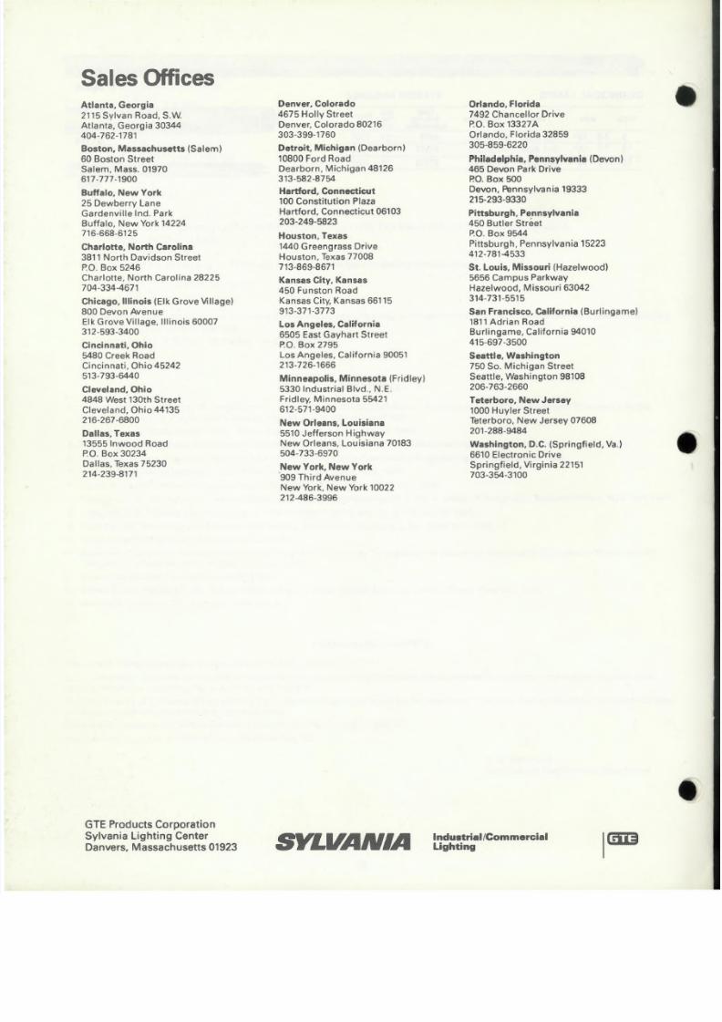
arrangement is illustrated in Figure 15.
For cooling rooms, use 15watts per 40
to 60 square feet, or 30 watts per 120 to
150 square feet of area. The lamps
should be mounted to irradiate as
much of the meat su r faces as possi ble.
Figure 15. Sanitary storage of meat.
Two types of mold are mostly responsi-
ble for the damage to the meat, namely
Sporotrichum carnis which produces
long white threads, and the Mucors
together with Thamnidium which forma greyish-white growth known as whis-
kers. Mold formation is also encour-
aged by the high relative humidity (r.h.
85 to 90 percent) wh ich is a desi rable
condition to prevent evaporation of the
moisture and shrinkage of the meat.
Mucors and other fungi are readily
destroyed by the 253.7nm radiation. It
must be borne in mind that careful
handling, cleanliness, low tempera-

8/3/2019 Sylvania Engineering Bulletin - Germicidal & Short Wave UV
http://slidepdf.com/reader/full/sylvania-engineering-bulletin-germicidal-short-wave-uv 9/16
tures, and similar. methods are preven-
tives of proven value.
Ultraviolet radiation of bactericidal
wavelengths is purely surface-effective.
Its penetrating power is negligible. In
the food industry, surface sterilization is
important in the endeavor to prevent
the infection not only of foodstuffs but
also of machines and tools.
There is little possibil ity of introducing
flavor or organoleptic changes as a
result of ultraviolet irradiation except
with fats and oils. This is due to the
generation of hydrogen peroxide H20,
and its strong oxidizing action.
Bakeries
Mold contamination is a major problem
in bakeries. Humidity and the constant
accumulation of fine dust makes it diffi-
cult to prevent mold formation even
with periodic cleaning. Ultraviolet irra-
diation of walls and ceilings to inhibit
spore formation with localized treat-
ment of the conveyor and bakery
products has proved effective. Germici-
dal irradiation of the walls and ceili ngs
in the fermentation room can reduce
the need for frequent cleaning of those
surfaces and thus reduce maintenance
costs. One 15-watt germicidal lamp is
commonly used for every 30 to 40
square feet of ceiling area or one 30-
watt germicidal lamp may be used for
every 75 to 100square feet of ceiling area.
Biological Supplies
Due to ever-i ncreasing demands for
biological supplies, pharmaceutical
houses use large volume testing pro-
cedures and mass production. These
large-scale operations demand
increased sanitary control measures
to insure that products are free of con-
taminating organisms. Germicidal
lamps play an important part in attain-
ing sterile areas for the production and
packaging of sterile material and in pro-
tecti ng laboratory workers from infection.
tion require an addit ional multiplying
factor of about 5, so that the exposures
to produce any given disinfection of
water are 40 to 50 times greater than
those required for dry air.
Absorptive liquids decrease the ger-
micidal intensity logarithmically with
the distance from the lamp. Minute
traces of iron compounds and organiccompou nds in liquids decrease the
transmission of germicidal energy.
Compounds of calcium, magnesium,
sodium, and aluminum sulfate in a liq-
uid increase the transmission of ger-
micidal energy, unless two or more of
the compounds form a precipitate.
In each specific liquid, there is a critical
dis ta nee fro m th € I germicida I lamp at
which 90% ofthe ultraviolet energy has
been absorbed. Ten percent afthe
energy, or less, remain to be transmit-
ted to the l iquid beyond that distance.
The distance for a 90% absorption,
called the "effective depth of penetra-
tion" may vary upward from a few
thousandths of an inch in milk, and
serums, or one-tenth of an inch in
wines and syrups, to five inches
through drinkable water of high trans-
mission and 10feet fa r some disti lied
water.
The design of systems depends upon
the particular requirements. Immersion
of the lamp directly in the water is un-
satisfactory because of the decrease in
ultraviolet output due to the cooli ng of
the tube by the water. When the lamp
has to be immersed in the water, it
shou Id be insta lied insi de aqua rtz tu be
for satisfactory ultraviolet transm ission.
This avoids the cooling and consequent
loss of lamp efficiency which would
result if the water were in contact with
the lamp wall. It also makes the clean-
ing and replacing of the lamp easier.
There must be a water-tight bond
between th-e enveloping tube ends and
the lamp ends for satisfactory
operation.
However, to avoid the extremes of
water temperatu re, the germicidal
lamp may be placed above the water
surface and partially enclosed in a
reflector. In this system, about 25% of
the ultraviolet output of the lamp
should reach the water surface direct ly;50% to 75% of the balance comes from
the reflector.
The basic techniques for purifying
water may be classified by the way the
germicidal lamps are used (immersed
or offset) and by the water system
(pressure or gravity). They combine
in three basic types: IP (immersed-
pressure), OP (offset-pressure), and OG
(offset-gravity) as shown in Figure 16.
IP
Figure 16. BASIC TYPES OF I '/ jI .TER DISINFECTING DEVICES
ALZAK
ALUMINUMREFLECTORSterilization of Liquids
Microorga nisms absorb consldera bly
less germicidal radiation when in very
humid air, or in water, than when in
very dry air. Waterborne E. coli, for
example, may require an 8 to 10times
greater exposure for a given kill than
dry airborne bacteria. The ultraviolet
absorption of water and mini mu m
provisions for circulation during irradia- Figure 17. SUGGESTED DIMENSIONS AND RATIN G S OF SMALL GRAV ITY TYPE WATER DISIN FEe TORS.·
9

8/3/2019 Sylvania Engineering Bulletin - Germicidal & Short Wave UV
http://slidepdf.com/reader/full/sylvania-engineering-bulletin-germicidal-short-wave-uv 10/16
An Alzak or Lurium aluminum reflector
on the upper cylindrical surface of the
chamber nearly doubles the germicidal
radiation throughout the lower half of
the chamber.
Figme 17 illustrates practical dimen-
sions for the gravity flow disi nfectors
wh ich C C I n be used with the 8. 15. and 30
watt lamps. They will provide 90% dis-infection, (with a 100% factor of safety)
of drinking water, transmitting 253.7
nanometer radiation effectively to a
depth of at Ieast 5 inchesif these rates
of flow are nat exceeded: GaTS, 100
gallons per hour; G15Ta, 200 gallons
per hour; and G30TB, 500 gallons per
hou r: . Where a com pact and powerful
source of germicidal energy is required,
it is suggested that quartz tubular high
intensity mercury lamps be used.
The continuous-flow capacity ratings
of the three basic techniques are tabu-
lated in Table V.The effective depth of
penetration of Table V determined in a
laboratory, fixes the maximum depth of
water to be processed in any device.
The water may otherwise be distributed
around or under the germicidal tubes in
any conven ient way that wi II intercept
all the energy from the tubes and
reflectors.
Antiquing Bottles
Some antique hobbyists use germicidallamps to produce old apothecary glass.
Exposure of preserve-type jars and bot-
tles to germicidal radiation can change
the COIOf of the gIass and age the bottle.
Certain impurities in the glass cause the
color to change. All glasses do not
col Of, but exposu re to the germicidal
energy for a few hours will i ndi cate
whether color changes will take place.
Safety precautions must be adhered to
at all time (See "Safety Precautions"],
Calculati.ons in the UltravioletSpectrum
Many of the techniques and equations
that are fa miliar in illu mi nati on engi-
neering for lighting calculations can be
used for the ultravi olet portion of the
spectrum. The various geometric
equati ons are basic to aIIradi ornetric
calculations. Photometry parallels
radiometry and is a special case of
TABLE V . 90% Disinfection of Liquids - Gallons per Hour"
No. 01G8TSt 2 3
No. of G15TS' 2
No. of G30:T8t 2 3 5 i 8 10 13 16
42 83 200 400 600 800 1000 1200 1600 2000
2 84 167 400 800 1200 1600 2000 2400 3200 4000
3 124 250 600 1200 1800 2400 3000 3600 4800 6000
~ 4 167 334 800 1600 2400 3200 4000 4800 6400 8000
0 ' < : 5 208 416 1000 2000 3000 4000 5000 6000 8000 10000OJ. J : : : . c
6 250 500 1200 2400 3600 4800 6000 7200 9600 12000'.5.-
'"I
7 292 584 1400 2800 4200 5600 7000 8400 11200 14000c c
'"0 8 333 666 1600 3200 4800 6400 8000 9600 12800 16000; ; ; > ' ~
.~ ro9 375 750 1800 3600 5400 7200 9000 10800 14400 18000
{,) . : : ." '" 10 417 834 2000 4000 6000 8000 10000 12000 16000 20000:. cw il)
12 500 1000 2400 4800 noo 9600 12000 14400 19200 24000,
15 625 1250 3000 6000 9000 12000 15000 19000 24000 30000
18 750 1500 3600 1200 10800 14400 18000 21600 28800 36000
24 1000 2000 4800 9600 14400 19200 24000 28800 38400 48000
For cu. It. per hour, multiply above by 0.13368; lor cu. in. per hour, by 231.0; for cu. in. per
mi nure, by 3.85.
tAllows lor 65% 01 bare lernp eff ic iency for lam p and ret lector combinat ion.
• Based on standard microorganism. E. coli .
radiometry. In the specific case of pho-tometry, terms from the luminous
system are used. The corresponding
radiometric terms can be used di rectly
in the same equations. Table VI gives
the basic quantities using standard
symbols ..Many other symbols and
units have been used in the past.
When considering light, the radiant
power (watts) is weighted, wavelength
by wavel.ength, usi ng the spectral sen-
sitivity of the eve, i.e., the luminous
spectral eff iciency function. If the
appropriate consta nt of proportional ityis used, the result is the lumen. In con-
siderinq the ultraviolet portion of the
spectrum, one can weight the radiantpower by an appropriate factor for each
wavelength, e.q, the erythemal.
response will! lead to the unit of E-viton.
Alternately, one may work di rectly with
the power at a particular wavelength or
with the power in a particular wave-
length band.
Several units of length are commonly
used for wavelength. These include:
the nanometer (nm) equal to 10-9
meters, the micron tu) equal to 10-5
meters, and the angstrom (A) equal to
10-'0 meters.
Atmospheric attenuation over dis-
tances of several meters can be entirely
TABLE VI. FUNDAMENTAL QUANTl~IES
R.d iometric System Photometr ic (Luminous) System
Symbol Oefining Equ.tion au.ntitY' Unit Ou an tll.,. Unit
0 Radiant energy joule luminous energy lumen second
dOih "'~- Aadia ... flux watt Luminous f l 1 u : x lumen
dt
dd> Incidenl tad i ant wall meter-2 Incident luminous fumen 100t-2
E E-- ftux density Ilux density Ilootcandle)dA
(irradiance! (illumination)
dih
Emitted radiant watt meter-2 EmiUed luminous lumen 1001-2
M M~- I Iux den sit I' Ilu~ densitydA Iradiant exitance] [lu minous exitance)
d d > b
,1- Ra.diant intensity watt luminous intensity lumendw steradian -I steradian-1
(cand'el~)
d'd>,
l l - Radiance watt mete r -~ lu mina,nce' lumen 100t-2dAdwcoc6 steradia n _, steradi,m-'
(candela foot -2)
Notes:a l The pref ixes "radiant" & . "luminous" of ten a,re omitted if no confusion will occur.
bl ru is the sol id ang le 01 a di fferent ia l Source e lement expressed in steradlans.
ci H is the anqle between a line of sight & . the normal to area dA.
d) See Reference 6 lor a complete discussion 01 th i s term & . l ts var ious un its . .
10

8/3/2019 Sylvania Engineering Bulletin - Germicidal & Short Wave UV
http://slidepdf.com/reader/full/sylvania-engineering-bulletin-germicidal-short-wave-uv 11/16
•
neglected for wavelengths above 300
nanometers in the ultraviolet. It
becomes appreciable below 300
nanometers and increases rapidly with
a decrease in wavelength. Atmospheric
effects should be considered, even for
distances of less than one meter, for
wavelengths below about 230 nanome-
ters. At a wavelength of 205 nanome-
ters, a typical value of atmospherictransmittance for a one meter path
might be 0.1. Absorpti on and scattering
are the two basic mechanisms of
attenuation. At a given wavelength, the
attenuation can easily vary by a factor
of 100 due to atmospheric conditions.
The reflectance of metals is dependent
on the method of surface preparation,
impurities, surface conditions, and
other factors. The difference for metals
between polished bulk material and
evaporated surfaces can be quite large.
Figure 18 shows typical values for spec-
ular surfaces. The high value shown for
aluminum is obtained for deposited
films in vacuum. Even avery brief
exposure to the atmosphere will signifi-
cantly reduce this value. Also, Figure 19
ill ustrates the typica I reflectance of van-ous materials in the germicidal region .
Transmittance values of materials are
dependent on sample thickness since
absorption losses vary exponentia Ily
with thickness. Figure 20 shows typical
transmittance curves of several com-
mon materials. The sample thicknessesare indicated, and surface ref lection
losses are included. The curves for
materials such as qua rtz vary consider-
ably with the particula r type. Transm it-
tance values for glass often vary
sig nifica ntly with tem peratu re; th is
effect is important for fi lters operating
near hot sources.
Measurement accuracy in the ultravio-
let, particularly at the shorter wave-
lengths, is considerably less than found
in the visible spectrum. Also, the optical
properties of the var ious system com-
ponents are not as well known for the
ultraviolet reg ion of the spectru m as for
the visible spectrum. Consequently,
approximate calculations, based on
typical data, often are adequate. Exam-
ples of typical calcu Iati ons are given
below. Several methods are possible
for solvl ng each of the problems. The
techniques used were selected to dem-
onstrate several types of calculations
TYPICAL REFLECTANCE IN THE GERMICIDAL REGION.
THE VALUE CAN VARY OVER A CONSIDERABLE RANGE
DEPENDING ON MATERIAL PURITY. METHOD OF PREP--ARATION, SURFACE CONTAMINATION AND FINISH,GEOMETRY OF INCIDENT AND COLLECTED RADIATIONEll: ...
1.0-:tzVIf)
NO.8
wuzs 0.6uw_J
u,Wa:
w
!; i::!x 0.2oa:a . . ., 0 . .
e X
Agure 18.
ENHANCED ALUMINUM
MAGNESIUM OXIDE
CALCIUM CARBONATE
'AlZAK' ALUMINUM ALUMINUM PAINT
WHITE PLASTER
CONSTRUCTION ALUMINUM
NICKEL
BLEACHED COTTON
COPPERWHITE PAPER
CHROME
SILVERSTAINLESS STEEL
LIG HT WALL PAPER
LINEN WOOD
BLEACHED WOOLo
e~ »>>:..~-r.-t.-,,-/ . / 0
~ . / . J - - - - - - -.4 . : . 1 - - - :
" .:-
r'~ ·-'-l-·~_._. ~ -, :
'.J
.6
WAV E : I , . . £ " " (HH -NANOrr.i(U:FII~
A ~ A I. U MI N Ui tl l
E !I - ALlAK FINi$H ALUMINUM
C & CHROIYIU i a I !
0- sn.VER
£- "ICI([1..
F- STAUu_ESs :nEEl .
Figure 19. Reflectance Values of CommonMaterials
and are not necessarily the most di recto
These examples are analogous to
lighting calculations as described in
standard textbooks on illuminating
engineering.
11
WHITE OIL PAINT
TYf lICl I.L. TRANSMI 'TTANI ;( CUR"~S Of COMMON MAl£FUAI.S
~OO=--~2'~O--~~~~~~~--~'OO
WitVEL.fN(1T ....- NA~MEtERS
. il l - W~HOOW GlASS. 10lNCk'I
&- P 'fRf )! 111774-, Imm
C - PY RE ::W :-g.14 i. Im m
0- CLEAR FUS£C OUAR'Tl, lem
E - DiSrlLL£O WATER, "6 IlfCH
F- POUSTYR£NE FI l. ", ,0066 I~CHINi ITIA l
G - POLYSTyRENE F ILM . , 0011 58 I tf CH - A rTER 1M HOUR
EXP'OSU ,. E TO S -j LA '- IP AT 6 INCH O ls tAHCe:
H- MY.Ali iI ~50AI. ,1!""1rI
Figure 20. Typical Transmittance Curves ofCommon Materials.

8/3/2019 Sylvania Engineering Bulletin - Germicidal & Short Wave UV
http://slidepdf.com/reader/full/sylvania-engineering-bulletin-germicidal-short-wave-uv 12/16
EXAMPLE 1: Determine the 253.7nm irradiance produced by a G8T51amp (5/8" diameter) for points A and B.
a) From Table I, the radiant flux at 253.7nm
M 0.059 . ~ IL = = --- = 0.019w In-' sr "
1T 7T
~ " " - 1 GeB_ L · ~ 1.=~
I .s"
l_l
r/ > =1.4w
b) The lamp can be approximated as a long cvlindrical radiator whose radiantexitance is
M =. !E_= 1.4w 0.059w in-2
A 1T x 5/8" x 12"
c) Assuming this is approximately Lambertian,
6
d) Since 12" > 3" > 5/8", the semi-infinite Lambertian strip is a good approximation for point A.
E'IT L ( width) 7T x 0.019 5/8" 0003 . -2 (48 -2)
A= = --= lwm or= O/Lwcm4 distance 4 3"
e) For point B, the inverse square law will be within a few percent for a Lambertian strip since the distance is 4 times the
maximum di mension. The radiant intensity in the direction of point B is
1= Lx Ap'oiected = 0.019 x (518" x 12") =0.143wsr-1
f) Finally, with the inverse square law we find
Many refinements could be made in these calculations to account for end effects, finite length of lamp, etc.; however, this
accuracy usually is not warranted.
EXAMPLE 2: Aparabolic trough reflector 12 inches long and with a focal length of 1-1/2 inches is located above the lamp of
Example 1.The reflector is specular Alzak aluminum, and the lamp is located along the focal line of the reflector.
What is the 253.7nm irradiance at Point B?
a) A quick check shows that point B is past the minimum inverse square distance for the reflector. Therefore, point B "sees" a
reflector radiance equal to the lamp radiance times the reflector reflectance (0.6 from Figure 19).
Lrel' = 0.019 x 0.6 = 0.0114win-2sr-1
b) If the reflector subtends the solid angle dw at point B and the solid angle is small, the reflector produces an irradiance of
(6" - 5/8") x 12" .Es = L,e!'dw = 0.0114 = 319 x 10-6w 1n-2
(48")2
c) Th e sum of the lamp irradi a nee pi u s th e reflector i rradi anee is the total iradi ance.
total Es=62 X 10-6 + 319 X 10-6 = 0.38 X 1O-3w in-2
12

8/3/2019 Sylvania Engineering Bulletin - Germicidal & Short Wave UV
http://slidepdf.com/reader/full/sylvania-engineering-bulletin-germicidal-short-wave-uv 13/16
EXAM PlE 3: Repeat Example 2 if the reflector fi nish is diffuse.
rb = 1 /2 x 1.4 =0.7w
a) The lamp is very close to the reflector. Consequently one-half of the lamp's radiant power is incident on the reflector.
b) A good diffuse Alzak su rface will have a reflecta nce value close to the specula r value; use 0.6. Since the reflector is sha llow,
neglect the interflections and curvature (these effects oppose and will tend to cancel), and assume it is a Lambert ian surface.
Thus,
M = 0.6 x 0.7w = 0.0058w in-2refl 6" x 12"
L0.0058 8· 2
,.fl =-- = 0.001 w 10- sr"1 1 "
c) The radiant intensity produced by the reflector is
I = Lrofl x Ao,oJ~c'ed = 0.0018 x (6" - 5/8") x 12" = 0.116w sr-1
d) The irradiance at point B dueto the reflector by the inverse square law is
0.116 0 6 • 2E =-- = 50 x 1 - w rnB (48")2
e) The sum of the lamp irradiance plus the reflector irradiance is the total irradiance.
total Ee= 62 X 10-6 + 50 X 10-6 = 0.112 X 1O-3w in-2
EXAMPLE: 4 A relative spectral power distribution curve, R (X), is shown for blue fluorescent lamps. If a particular blue lamp is
rated at 1160l rn, determine the multiplierforthe curve so that it is absolute in watts per micron (WJ.!,-1).
a) Choose a convenient scale for graphical ytork, say the 15 x 20 cm shown. Multiply the relative power curve R O d by the
lumi nou s spectral efficiency function VIA) at each wavelength. Then measu re the area under th is product curve; it turns out
to be 21.0 cm2 on the drawing size suggested.
b) A unit length on the relative power scale is 10 em and a unit length on the wavelength scale is 50 cm. Therefore, a unit areaon the graph scale is lOx 50 = 500 cm2 on the drawing. The area under the product curve on the graph scale is
21.0cm2
=0.042
500cm2
c) If K is the multipler to put the curve in absolute units, then
r b =683 (1mw-'if,[; R (X)) (WJ.!,-I)VIA) dA ( J . ! , ) = 1160 lrn
1.70 =K£R~) V(>")d>..
~I~ , 15
s~ 10
~'".~~~ .s
10
d) The final integral above is the area under the product curve found in part (b). Thus,
K = 1.70 = 40.50.042
,-,I \
I \ V I X I
I V\
\\\
\
\
\
,5 .6
WAvEL[N{i.TH !J r
o 10
"
EXAMPLE 5: Lamps ofthetype described in example 4 produce an illumination of 121m ft-2 ata particular point. What is the
irradiance in the . 3 J . ! , to.4J.!,band at that point?
a) If th e radi ant power is acted on selectively with respect to wavelength, then it is necessary to follow it through the system
applying the proper spectral reflecta nce and spectral transmitta nee fu nctl ons. However, the problem is simple if the radiant
power is acted on non-selectively, i.e., all wavelengths of interest are affected equally. In this example, direct lamp radiation
can be considered in this manner. Also, any reflecting or transmitting material that equally attenuates all wavelengths in the
. 3 J . ! , to . 4 J . ! , region and the visible reg ion of the spectrum could be present.
13
8/3/2019 Sylvania Engineering Bulletin - Germicidal & Short Wave UV
http://slidepdf.com/reader/full/sylvania-engineering-bulletin-germicidal-short-wave-uv 14/16
b) The radia nt power between .3/L and . 411-emitted by the lamp is the area under th s absolute spectra I power distri butien
curve between these wavelengths. Measuring this region on our large scale drawing, we find an area of 10.5Cm2. On the
basic graph scale, the area is
10.5 cm2
=0.021
SOOcm2
c) The radiant power is given by
/
.4
4 > .3•.4 '" [ K R ( > " ) ] (WtL-1) d > . . (M )
. 3
/
.4
1 > .J . .4 = = K A U " ' ) d"
.3
d) This final Integral is the area under the curve found in part (b). The value of K is known from example 4.
l / J ,3 . . • ' " 40.5 x 0.021 = = 0.8Sw
e) The ratio of the emitted poweri n the .3/L to .4tL band to the emitted luminous flux is
.85w = = 0.73 x 1O-3w lrn"1160lm
f) Under the stated conditions of non-selected flux control, this ratio is preserved throughout the system. At a point where the
illumination is 121m ft-2, we find
E.J•.4 = = 121m ft-2
x 0.73 X 10-3
w Im-1
= 0.0088wft-2
REFERENCES
1, Huff , C. , Smith, H. , Boring, W, and Clarke, N., "Study of Ultraviolet Disinfection of Water and Factors in Trsatrnant Ef fic iency," Publ ic
Health Reports, U.S. Public Health Service, Vol. 80, p. 695,705, August 1965,
2. Kaufman, J., "Introducing SI Units," Ilium. Engr., Vol. 63, p. 537, October '968.
3. I.E.S. Lighting Handbook, Applications Volume, 6th Edition. p. 19-14 to 19-18. Illuminating Engineering Society, New York 1981,
4. American National Standard: Nornenclatu re and Def in itions for I Ilu minali ng Eng ineering, ANSIIIES RP-16-1980.
5. Koller, L., Ultraviolet Radia,lion, John Wiley and Sons, Inc., New York, 1965 . .
6. levin, R., "Luminance - A Tutorial Paper," Jour. SMPTE, Vol. 77, p. 1005, Oct. 1968.
7, Nicodemus, f. , "Radiornetrv," Applied Optics and Opttcal Engineering, Ch. 8, Vol. 4,editor:R. Ki,ngslake. Academic Press. New York 1967.
8. Nicodemus,F., "Optical Resource Letter on Radiometry, " JOSA, Vol. 59, p. 243, March 1969.9. Sum mer, w . , Ultraviolet and Infrared Eng ineering, Interscience Publishers, Inc., New York 1962.
10. Ult ra-Violet Products, lnc., San Gabriel, California.
11, American Conference of Governmentel and Industrial Hygienists, Threshold Limit Values For Chemical Substances In Work.room Air
Adopted by ACGIH For 1977, ACGI H, Cincin nati 1977.
12, International Light Inc., NeWburyport , Mass.
13. Sliney. D. and Wol,barsht, M., Safety With lasers and Other Optical Sources, Plenum Press, New York 1980.
14. American Ult raviolet Co., Chatham, New Jersev,
ACKNOWLE iDGEMENTS
The author wishes to express his appreciation to the foHow.ing:
Dr. L. J.8uttol ph, Engineer on the staff of the llluml nat ing 'Engi neeri ng Society for his assistance in supplying information on germicidal
lamp applications, including Fig. 4, 6,15-18, and Table m ,Dr. Robert Levin of the General Engineering Dapt., Sylvania Lighting Center, for his assistance in wriiting the section on the calculations in the
ultraviolet spectrum, and providing technical data.
Ultra-Violet Products, Inc. of San Gabriel, California, for Fig. 5A, 58.,11, and 13.
International Light Inc. of Newburyport, Mass. for Fig. 5C.
C. C. MPELKAS
Commercial Engineering Department
14

8/3/2019 Sylvania Engineering Bulletin - Germicidal & Short Wave UV
http://slidepdf.com/reader/full/sylvania-engineering-bulletin-germicidal-short-wave-uv 15/16
G30TBG ER M ICID AL L AM PS STARTER REQUIRED
Lamp Std.HoursW atb Bu lb B a s e Ducrlp ilon O rdering Pli.LIfeAbbreviation Qll·
8 T - 5 1 2 " Min . B i~ in Germicidal 0 8 T 5 24 7500G15T8
15 T - 8 1 8 " Med . B ip i n Germicidal & 1 5 T 8 24 7500
3 0 T · 8 3 6 " Med . B ip i n Germicid!l l G 3 0 T 8 2 4 __7500
G8TS
15
8/3/2019 Sylvania Engineering Bulletin - Germicidal & Short Wave UV
http://slidepdf.com/reader/full/sylvania-engineering-bulletin-germicidal-short-wave-uv 16/16
Sales O ffic es
Atlanta, Georgia
2115 Sylvan Road,S. W.
At lanta, Georgia 30344
404·762·1781
Boston. Massachuset ts (Salem)
60 Boston Street
Salem, Mass. 01970617·777·1900
Buffalo, New York
25 Dewberry Lane
Gardenville Ind. Park
Buf falo, New York 14224
716·668·6125
Charlot te, North Carol ina
3811 North Davidson St reet
PO. Box 5246
Charlot te, North Carolina 28225
704·334·4671
Chicago, I ll inois (Elk Grove Vil lage)
800 Devon Avenue
Elk Grove Village, I llinois 60007
312·593·3400
Cincinnati , Ohio5480 Creek Road
Cincinnat i, Ohio 45242
513·793-6440
Cleveland, Ohio
4848 West 130th Street
Cleveland, Ohio 44135
216·267 ·6800
Dallas, Texas
13555 Inwood Road
PO. Box 30234
Dallas, Texas 75230
214·239·8171
GTEProducts CorporationSylvania lighting Center
Danvers, Massachusetts 01923
Denver, Colorado
4675 Hol ly Street
Denver, Colorado 80216
303·399·1760
Detroit . Michigan (Dearborn)
10800 Ford Road
Dearborn, Michigan 48126313-582·8754
Hartford. Connecticut
100 Const itut ion Plaza
Hart ford, Connecticut 06103
203-249-5823
Houston, TeJC8s
1440 Greengrass Drive
Houston. Texas 77008
713·869·8671
Kansas City, Kansas
450 Funston Road
Kansas City. Kansas 66115
913·371·3773
los Angeles, Cal ifornia
6505 East Gayhart Street
PO. Box 2795Los Angeles, California 90051
213-726-1666
Minneapolis, Minnesota (Fridley)
5330 Industrial Blvd., N. E .
Fridley, Minnesota 55421
612·571·9400
New Orleans, Louisiana
5510 Jefferson Highway
New Orleans, Louisiana 70183
504-733·6970
New York, New York
'909 Third Avenue
New York, New York 10022
212-486-3996
SYLVANIA
Orlando, Florida
7492 Chancel lor Drive
PO. Box 13327A
Orlando, Florida 32859
305·859·6220
Philadelphia. Pennsylvania (Devon)
465 Devon Park DriveP.O.Box 500
Devon, Pennsylvania 19333
215·293·9330
Pittsburgh, Pennsylvania
450 Butler Street
P.O.Box 9544
Pit tsburgh, Pennsylvania 15223
412·781-4533
St. Louis, Missouri (Hazelwood)
5656 Campus Parkway
Hazelwood. Missouri 63042
314·731·5515
San Francisco, California (Burl ingame)
1811Adrian Road
Burlingame, Cal ifornia 94010
415·697 ·3500Seattle, Washington
750 So. Michigan Street
Seatt le, Washington 98108
206·763·2660
Teterboro, New Jersey
1000 Huyler Street
Teterboro, New Jersey 07608
201·288·9484
Washington, D.C. (Spr ingf ield, Va)
6610 Electronic Drive
Springfield, Virginia 22151
703·354·3100
Indust,rial/Commercial
Lighting I C i m