switchyard
TRANSCRIPT

SWITCHYARD
www.powerpointpresentationon.blogspot.comwww.powerpointpresentationon.blogspot.com

What is a Switchyard ?
It is a switching station which has the following credits :
(i) Main link between Generating plant and Transmission system, which has a large influence on the security of the supply.
(ii) Step-up and/or Step-down the voltage levels depending upon the Network Node.
(iii) Switching ON/OFF Reactive Power Control devices, which has effect on Quality of power.

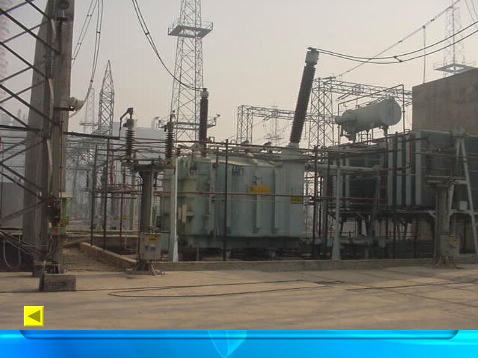
SWITCHYARD EQUIPMENTS
• Equipments commonly found in switchyard :1. Lightening arrestor
2. Current transformer
3. Voltage transformer
4. Power transformers / I.C.T.
5. Bus bar and clamp fittings
6. Support structure
7. Isolators
8. Circuit Breaker
9. Wave traps
10. Earthing switch

Functions of various equipment :
* Transformers : - Transforms the voltage levels from higher to lower level or vice versa, keeping the power constant. * Circuit breakers : - Makes or automatically breaks the electrical circuits under Loaded
condition. * Isolators : - Opens or closes the electrical circuits under No-load conditions. * Instrument transformers : - For stepping-down the electrical parameter (Voltage or Current) to a
lower and safe value for Metering and Protection logics. * Earth switch : - Used to connect the charged body to ground to discharge the trapped
charge to have a safe maintenance zone.
Functions of various equipment :
* Lightning arrestors : - Safe guards the equipment by discharging the high currents due to Lightning. * Overhead earth wire : - Protects the O/H transmission line from Lightning strokes. * Bus bar : - Conductors to which a number of circuits are connected. * Wave Traps/Line traps : - Used in PLCC circuits for Communication and Protection of
Transmission lines * Reactive Power control devices : - Controls the reactive power imbalance in the grid by switching
ON/OFF the Shunt Reactors, Shunt Capacitors etc., * Current Limiting Reactors : - Limits the Short circuit currents in case of faulty conditions.


Switchyard One line DiagramTransfer Bus 400 KV
Main Bus II
Main Bus I
CB CBCB
GT20.5/400KV
Gen Bay Feeder Bay
Bus
Isolator
Transfer Bus Bay
Bus Switching Schemes : Bus Bar Schemes
* Single Sectionalised bus * Main & Transfer bus * Sectionalised Main bus with Transfer bus * Sectionalised Double Main & Transfer busBreaker Schemes * Ring bus * One and Half breaker
* Double bus Double breaker

* Single Sectionalized Bus-bar system :
I/C Feeders
O/G Feeders
Bus-bar
CB
Isolators

* Main & Transfer Bus-bar system :
I/C Feeders
Transfer Bus
CB
Isolators
Main Bus
Bus Coupler

* Ring Bus system :
I/C Supply
O/G feeder
Bus
CB

* One and Half Breaker scheme :
Tie CB
Main 1
Main 2
Feeder 1
Feeder 2Feeder 2
What is a Switchgear ?
“The apparatus used for Switching, Controlling and Protecting the Electrical Circuits and equipment”.
Need of Switchgear :
* Switching during normal operating conditions for the
purpose of Operation and Maintenance.
* Switching during Faults and Abnormal conditions and
interrupting the fault currents.

Relays
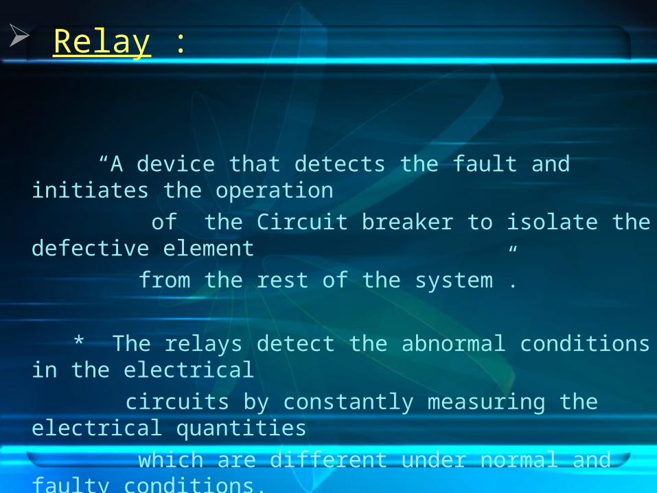
Relay :
“A device that detects the fault and initiates the operation
of the Circuit breaker to isolate the defective element
from the rest of the system”.
* The relays detect the abnormal conditions in the electrical
circuits by constantly measuring the electrical quantities
which are different under normal and faulty conditions.

Requirements of Protecting relaying : Selectivity - Ability to select the faulty part and isolate that
part without disturbing the rest of the system. Speed - Ability to disconnect the faulty part at the
earliest possible time. Sensitivity - Ability of the relay to operate with low value of
actuating quantity. Reliability - Ability of the system to operate under pre-
determined conditions
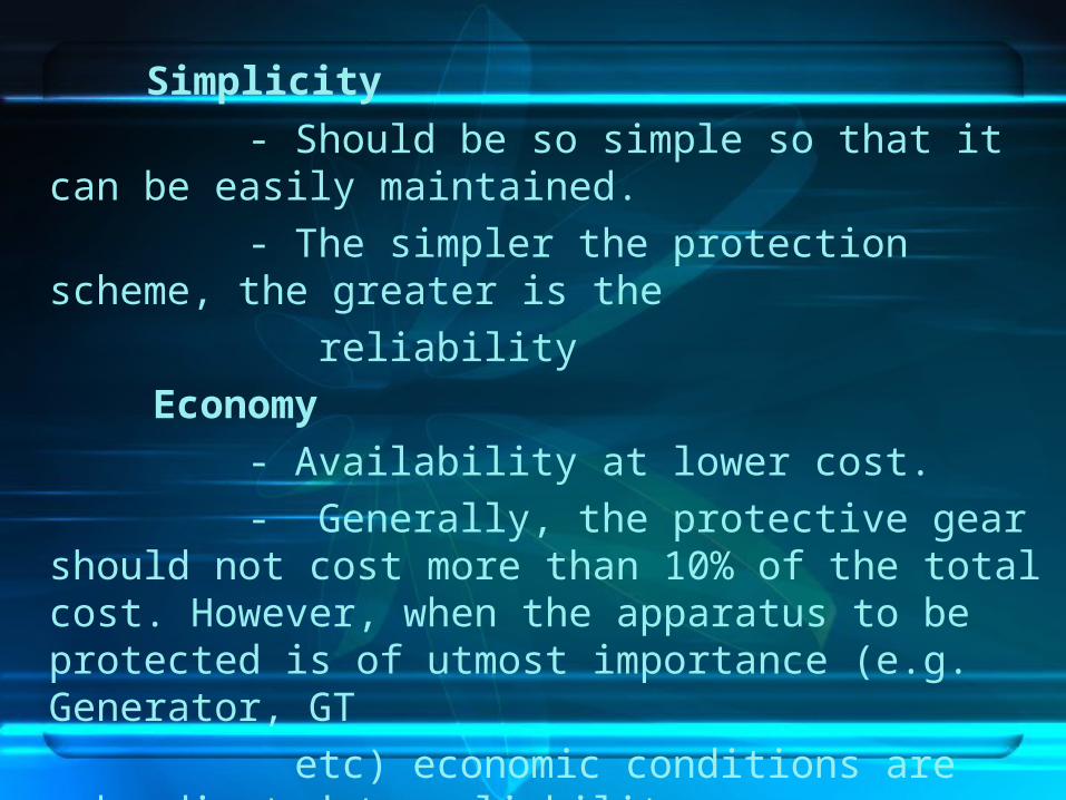
Simplicity
- Should be so simple so that it can be easily maintained.
- The simpler the protection scheme, the greater is the
reliability
Economy
- Availability at lower cost.
- Generally, the protective gear should not cost more than 10% of the total cost. However, when the apparatus to be protected is of utmost importance (e.g. Generator, GT
etc) economic conditions are subordinated to reliability.

Basic classification of Relays based on Function :
* Over current
* Under Voltage * Impedance * Under Frequency * Directional
Circuit Breakers
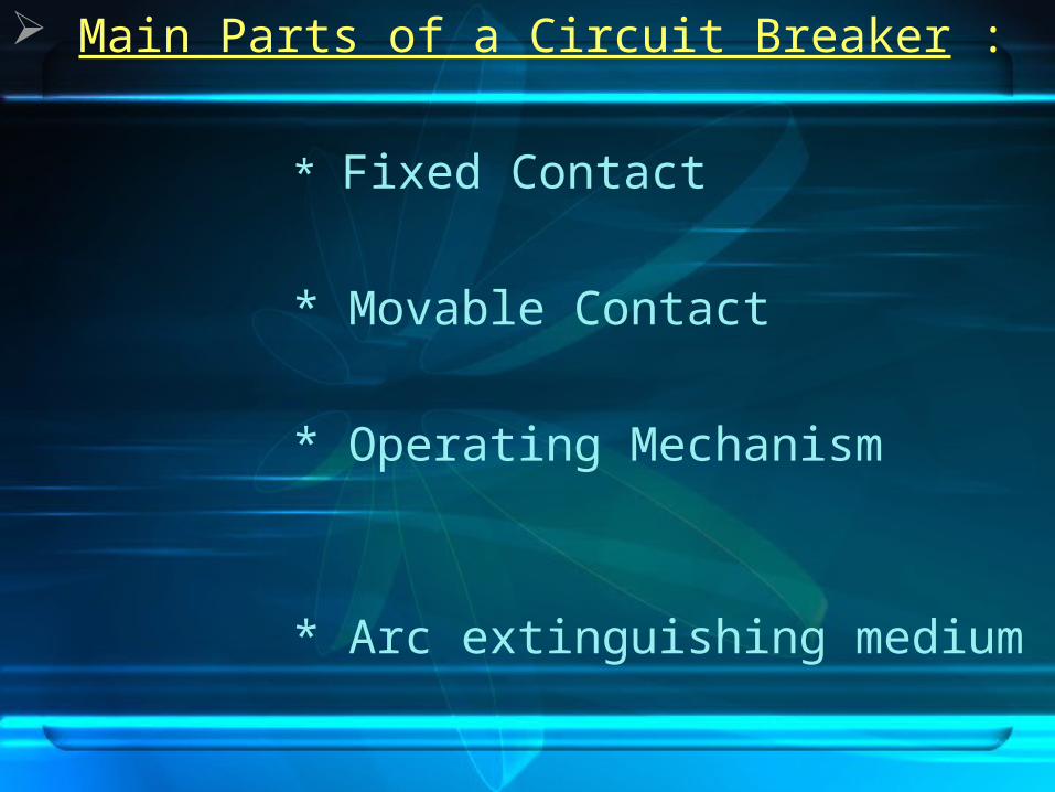
Main Parts of a Circuit Breaker : * Fixed Contact
* Movable Contact
* Operating Mechanism
* Arc extinguishing medium
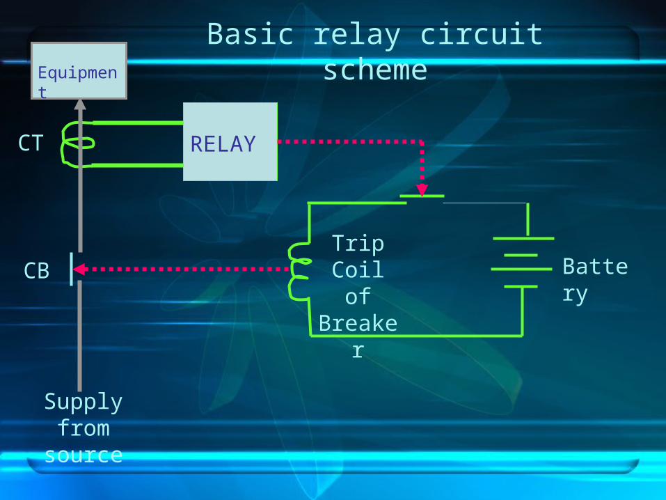
Supply from source
Equipment
RELAY
BatteryTrip Coil
of Breaker
CB
CT
Basic relay circuit scheme
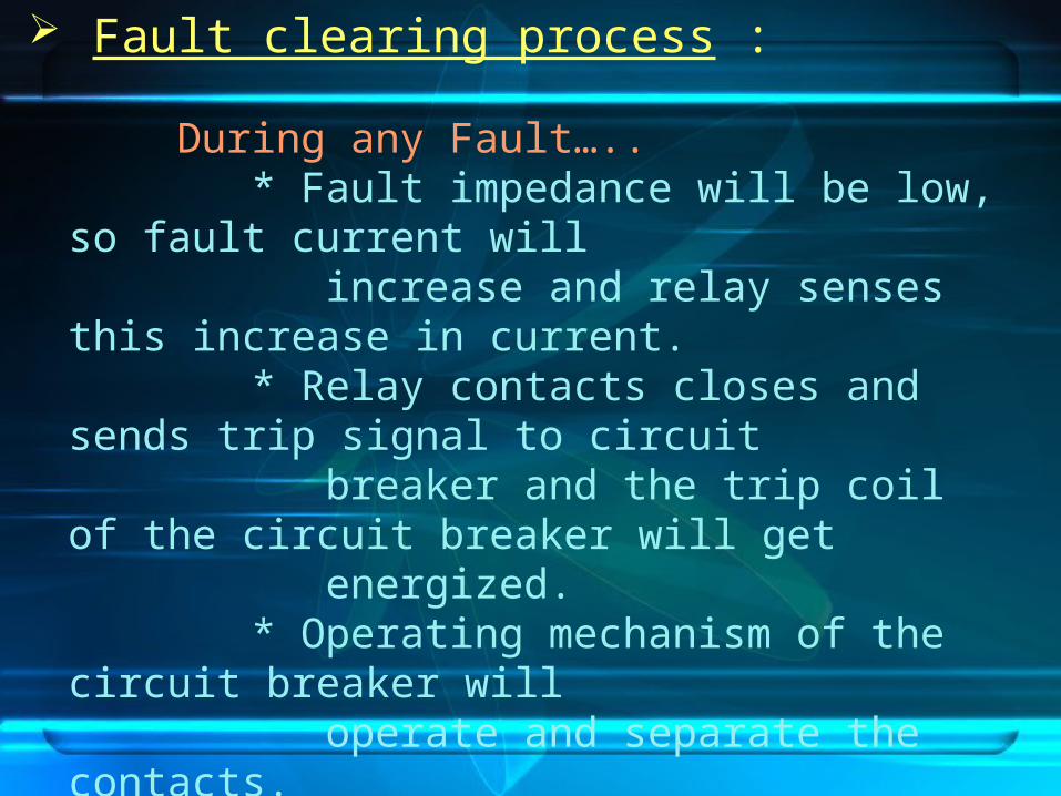
Fault clearing process :
During any Fault….. * Fault impedance will be low, so fault
current will increase and relay senses this increase
in current. * Relay contacts closes and sends trip
signal to circuit breaker and the trip coil of the circuit
breaker will get energized. * Operating mechanism of the circuit
breaker will operate and separate the contacts. * Arc will be initiated between the
contacts and it is extinguished by suitable methods.
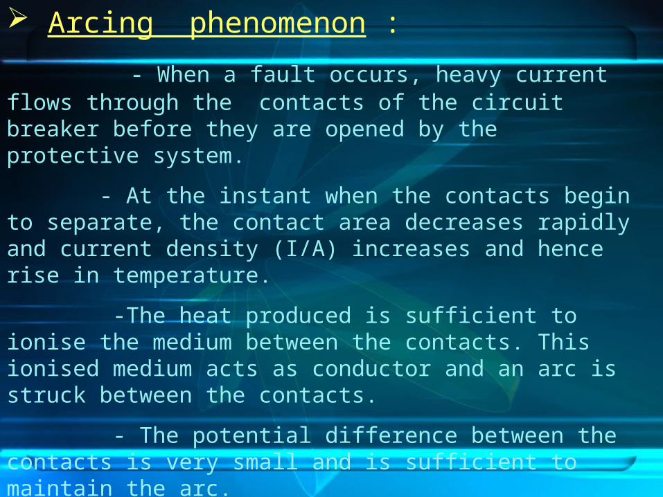
Arcing phenomenon :
- When a fault occurs, heavy current flows through the contacts of the circuit breaker before they are opened by the protective system.
- At the instant when the contacts begin to separate, the contact area decreases rapidly and current density (I/A) increases and hence rise in temperature.
-The heat produced is sufficient to ionise the medium between the contacts. This ionised medium acts as conductor and an arc is struck between the contacts.
- The potential difference between the contacts is very small and is sufficient to maintain the arc.
- The current flow depends upon the Arc resistance.
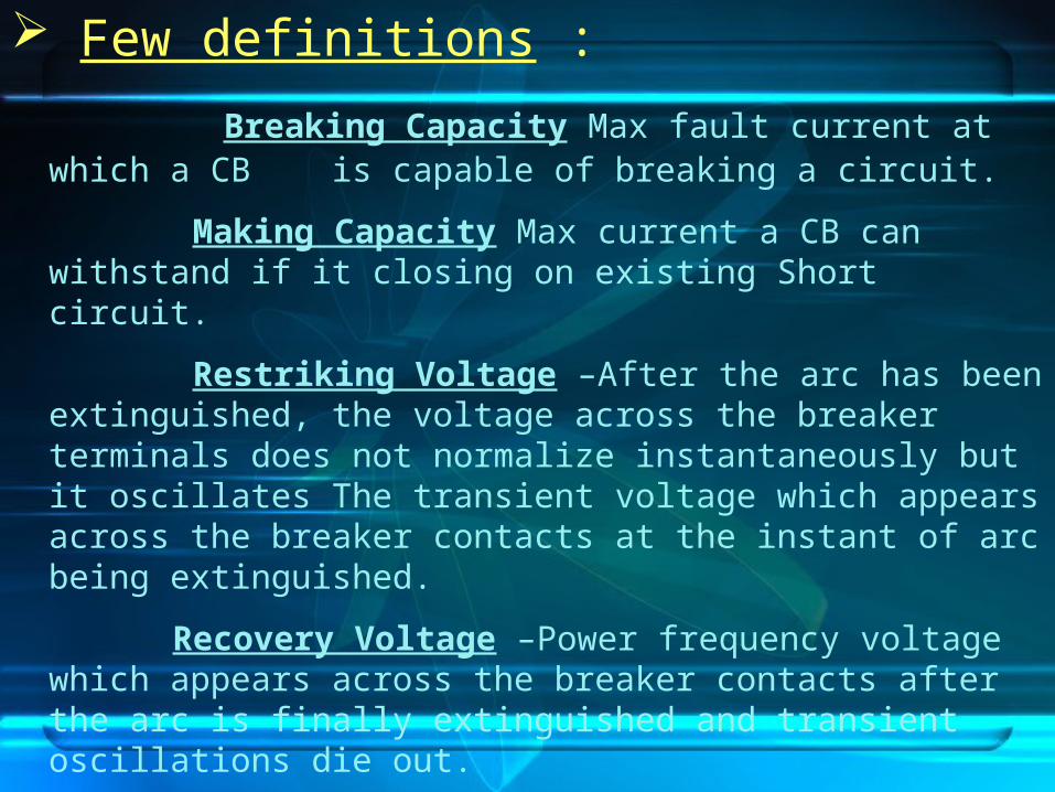
Few definitions :
Breaking Capacity Max fault current at which a CB is capable of breaking a circuit.
Making Capacity Max current a CB can withstand if it closing on existing Short circuit.
Restriking Voltage –After the arc has been extinguished, the voltage across the breaker terminals does not normalize instantaneously but it oscillates The transient voltage which appears across the breaker contacts at the instant of arc being extinguished.
Recovery Voltage –Power frequency voltage which appears across the breaker contacts after the arc is finally extinguished and transient oscillations die out.
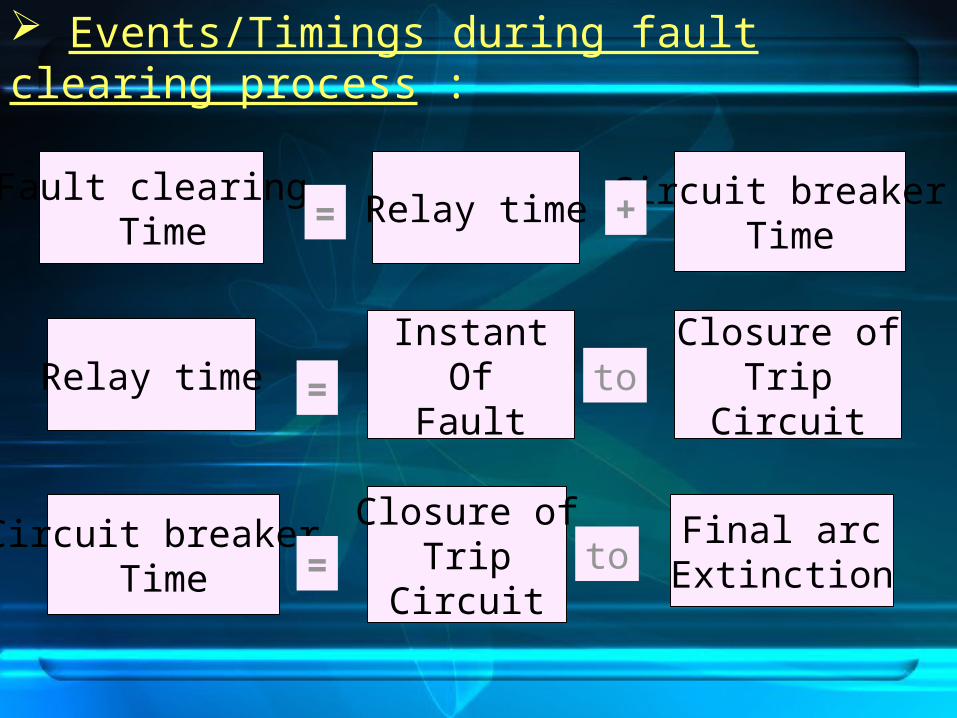
Events/Timings during fault clearing process :
Fault clearing Time
Relay time Circuit breaker Time
InstantOf
Fault
Closure ofTrip
Circuit
Final arcExtinction
Circuit breaker Time
Closure ofTrip
Circuit
= +
=
= to
toRelay time

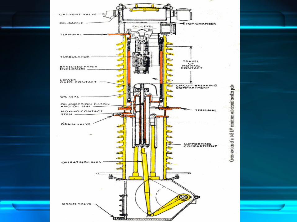
Various types of CBs : (i) Miniature CB (ii) Air Break CB (iii) Air Blast CB (iv) Oil CB (v) SF6 CB (vi) Vacuum CB
Bulk Oil CB
Minimum Oil CB

Air Break CB :

Air Blast CB :
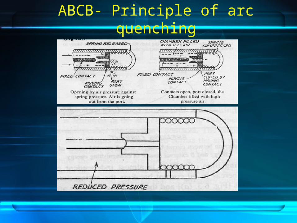
ABCB- Principle of arc quenching
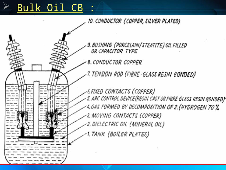
Bulk Oil CB :


Minimum Oil CB :
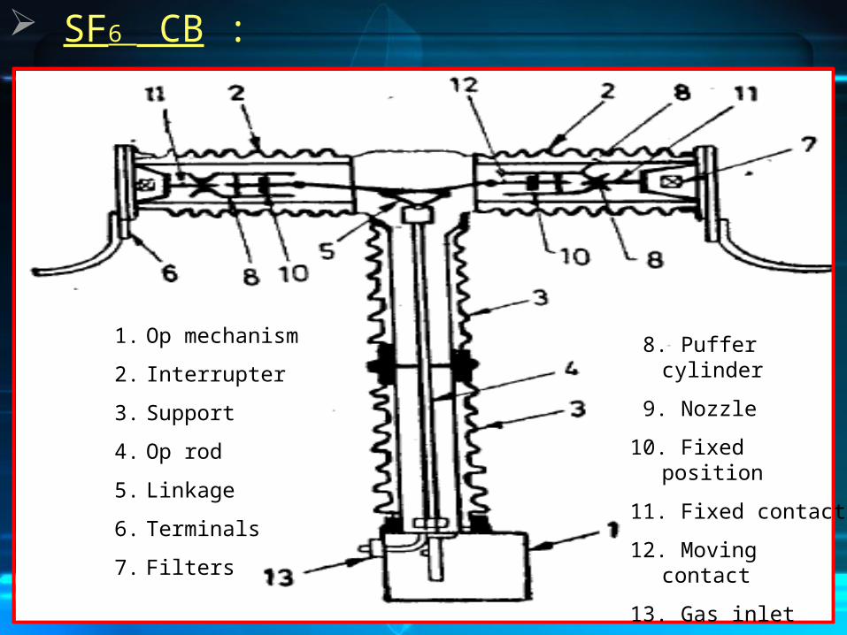
SF6 CB :
1. Op mechanism
2. Interrupter
3. Support
4. Op rod
5. Linkage
6. Terminals
7. Filters
8. Puffer cylinder
9. Nozzle
10. Fixed position
11. Fixed contact
12. Moving contact
13. Gas inlet
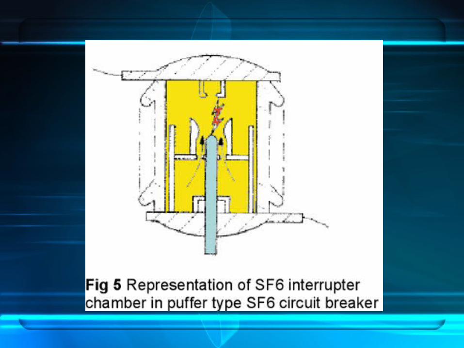


* Inert gas with high dielectric strength.
* Colour less and odour less.
* Non-toxic and non- inflammable.
* Sf6 is blown axially to the arc, hence it removes the heat by axial convection and radial dissipation. As result the arc dia reduces and comes to zero at current zero.
* Gas pressure in the chamber is at 5 ksc.
* SF6 is filled at a pressure of 12 ksc in the tank and maintained by means of an individual or a common compressor.
* The decomposition products of arcing are not explosive hence no chance of fire.
Disadvantages
* SF6 gas condensates at low temperature & high pressure
Advantage of SF6

Vacuum CB :


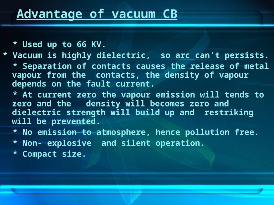
* Used up to 66 KV.* Vacuum is highly dielectric, so arc can’t persists. * Separation of contacts causes the release of metal vapour from
the contacts, the density of vapour depends on the fault current. * At current zero the vapour emission will tends to zero and the
density will becomes zero and dielectric strength will build up and restriking will be prevented.
* No emission to atmosphere, hence pollution free. * Non- explosive and silent operation. * Compact size.
Advantage of vacuum CB

Disadvantages
* High initial cost.
* Surge suppressors (R or RC combination) are to be connected at load side for limiting switching over-voltage while switching low pf loads.
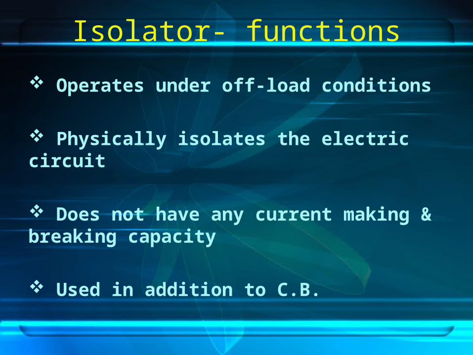
Isolator- functions
Operates under off-load conditions
Physically isolates the electric circuit
Does not have any current making & breaking capacity
Used in addition to C.B.
Earth-Switch
Operated when Isolator is open.
Connected between Line conductor and Earth whenever required.
Discharge the voltage trap in line.

CB
Earth S/W
IsolatorIsolator Load
Source
* Practically, Pantograph type Earth switches were used.
Current transformers
Purpose :
- To step-down the high magnitude of current to a safe value to incorporate Measuring and Protection logics
• Current transformers are used for the instrumentation, protection or metering of power systems and are normally installed on each side of a circuit breaker.
Voltage transformers
Purpose :
- To step-down the high magnitude of voltage to a safe value to incorporate Measuring and Protection logics.
• Voltage transformers serve a number of functions in a power system. They are required for the operation of many types of instrumentation and relay protective systems. They measure voltage and in conjunction with CT , they measure power. They feed synchronizing equipment. They can be used as coupling capacitors in power line carrier network.

CAPACITIVE VOLTAGE TRANSFORMER
• - Primary voltage is applied to a series of capacitors group. The voltage across one of the capacitor is taken to aux PT. The secondary of the aux PT is taken for measurement and protection.
• SECONDARY VOLTAGES(110 VOLTS AC) FOR METERS AND ENERGY METERS
• VOLTAGES FOR PROTECTIVE RELAYS• VOLTAGES FOR SYNCHRONIZING • DISTURBANCE RECORDERS AND EVENT LOGS• OVERFLUX RELAYS• PLCC

Purpose :
- To discharge the high voltage surges in the power
system due to lightning to the ground. Apparatus to be protected :
* Overhead lines………Earth/Ground wires (PA=30 deg)
* HV equipment………LAs
* Substation…………...Lightning Masts, Earth wires
Lightening Arrestor

Types : Rod gap LA : Power Line
Insulator
Equipment body
Rod gap
* Gap length is such that the break-down occurs at 80% of the spark voltage
* After the surge, the arc in the gap is maintained by the normal supply voltage. So, only used as a back-up.

Wave Trap

WaveTrap
WaveTrap
Transmission Line
* Wave trap is used for Protection of the transmission line and communication between the Substations.
* VHF signal is transmitted from one end to the another through the same power line.
* Sends inter-trip signal to the other end CBs so that fault can be isolated at the earliest time.
To control roomof S/S-2
To control roomof S/S-1
S/S-1S/S-2

THANK YOU