switching p supplies
TRANSCRIPT
8/3/2019 Switching p Supplies
http://slidepdf.com/reader/full/switching-p-supplies 1/12
36SWITCHING
POWER SUPPLIES
1104
CONTENTS AT A GLANCE
Power supplies play a vital role in the operation of PCs and their peripherals—a supply
converts commercial ac into various levels of dc that can be used by electronic and electro-
mechanical devices. For the purposes of this book, power supplies are broken into three
classes: linear (dc) supplies, switching (dc) supplies, and high-voltage supplies. Although
linear power supplies are popular because of their simplicity, they are inefficient. As a re-sult, linear supplies are typically relegated to low-end applications, such as ac adapters and
battery eliminators, and are not covered in this edition of the book. On the other hand,
switching power supplies are well-entrenched as the primary power source in PC applica-
tions. Virtually all PC and peripheral designs incorporate a switching supply. This chap-
ter illustrates the operation and troubleshooting approaches for a switching power supply.
Understanding Switching SuppliesConcepts of switching regulation
Connecting the Power SupplyAT-style power connections
Drive power connections
ATX/NLX-style power connections
Optional ATX/NLX power connector
Voltage tolerances
Troubleshooting Switching PowerSupplies
Tips for power-supply service
An example power supplySymptoms
Further Study
8/3/2019 Switching p Supplies
http://slidepdf.com/reader/full/switching-p-supplies 2/12
Understanding Switching SuppliesThe great disadvantage to linear power supplies is their tremendous waste. At least half of
all power provided to a linear supply is literally “thrown away” as heat—most of this
waste occurs in the regulator. Ideally, if just enough energy was supplied to the regulator
to achieve a stable output voltage, regulator waste could be reduced almost entirely and
supply efficiency would be vastly improved.
CONCEPTS OF SWITCHING REGULATION
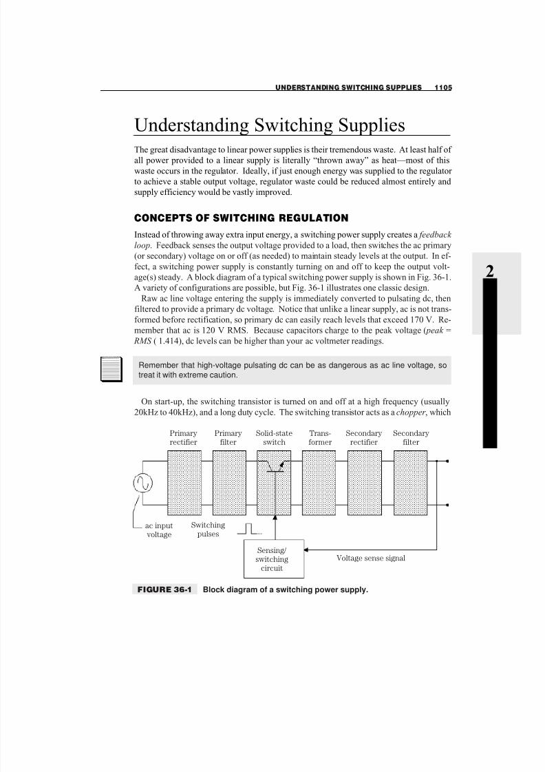
Instead of throwing away extra input energy, a switching power supply creates a feedback
loop. Feedback senses the output voltage provided to a load, then switches the ac primary
(or secondary) voltage on or off (as needed) to maintain steady levels at the output. In ef-
fect, a switching power supply is constantly turning on and off to keep the output volt-age(s) steady. A block diagram of a typical switching power supply is shown in Fig. 36-1.
A variety of configurations are possible, but Fig. 36-1 illustrates one classic design.
Raw ac line voltage entering the supply is immediately converted to pulsating dc, then
filtered to provide a primary dc voltage. Notice that unlike a linear supply, ac is not trans-
formed before rectification, so primary dc can easily reach levels that exceed 170 V. Re-
member that ac is 120 V RMS. Because capacitors charge to the peak voltage ( peak =
RMS ( 1.414), dc levels can be higher than your ac voltmeter readings.
On start-up, the switching transistor is turned on and off at a high frequency (usually20kHz to 40kHz), and a long duty cycle. The switching transistor acts as a chopper, which
UNDERSTANDING SWITCHING SUPPLIES 1105
2 S Y S T E M DAT A
AND
T R O UBL E
S H O OT I N GPrimary
rectifier
Primary
filter
Solid-state
switch
Trans-
former
Secondary
rectifier
Secondary
filter
Switching
pulsesac input
voltage
Sensing/
switching
circuit
Voltage sense signal
FIGURE 36-1 Block diagram of a switching power supply.
Remember that high-voltage pulsating dc can be as dangerous as ac line voltage, so
treat it with extreme caution.

8/3/2019 Switching p Supplies
http://slidepdf.com/reader/full/switching-p-supplies 3/12
breaks up this primary dc to form chopped dc, which can now be used as the primary sig-
nal for a step-down transformer. The duty cycle of chopped dc will affect the ac voltagelevel generated on the transformer’s secondary. A long duty cycle means a larger output
voltage (for heavy loads) and a short duty cycle means lower output voltage (for light
loads). Duty cycle itself refers to the amount of time that a signal is “on,” compared to its
overall cycle. The duty cycle is continuously adjusted by the sensing/switching circuit.
You can use an oscilloscope to view switching and chopped dc signals. Figure 36-2 illus-
trates a more practical representation for a switching supply.
Ac voltage produced on the transformer’s secondary winding (typically a step-down
transformer) is not a pure sine wave, but it alternates regularly enough to be treated as ac
by the remainder of the supply. Secondary voltage is re-rectified and re-filtered to form a
secondary dc voltage that is actually applied to the load. Output voltage is sensed by the
sensing/switching circuit, which constantly adjusts the chopped dc duty cycle. As load in-
creases on the secondary circuit (more current is drawn by the load), output voltage tends
to drop. This is perfectly normal, and the same thing happens in every unregulated supply.However, a sensing circuit detects this voltage drop and increases the switching duty cy-
cle. In turn, the duty cycle for chopped dc increases, which increases the voltage produced
by the secondary winding. Output voltage climbs back up again to its desired value. The
output voltage is regulated.
The reverse will happen as load decreases on the secondary circuit (less current is drawn
by the load). A smaller load will tend to make output voltage climb. Again, the same ac-
tions happen in an unregulated supply. The sensing/switching circuit detects this increase
in voltage and reduces the switching duty cycle. As a result, the duty cycle for chopped dc
decreases and transformer secondary voltage decreases. Output voltage drops back to its
desired value. The output voltage remains regulated.
Consider the advantages of a switching power circuit. Current is only drawn in the pri-
mary circuit when its switching transistor is on, so very little power is wasted in the pri-
mary circuit. The secondary circuit will supply just enough power to keep the load voltageconstant (regulated), but very little power is wasted by the secondary rectifier, filter, or
switching circuit. Switching power supplies can reach efficiencies higher than 85% (35%
1106 SWITCHING POWER SUPPLIES
ac Input
voltage
High-frequency
switching
pulses
Sensing/
switching
circuit
Voltage sense
Switching
transistorQ
dc Output
voltage
FIGURE 36-2 Simplified diagram of a switching power supply.
8/3/2019 Switching p Supplies
http://slidepdf.com/reader/full/switching-p-supplies 4/12

8/3/2019 Switching p Supplies
http://slidepdf.com/reader/full/switching-p-supplies 5/12
AT-STYLE POWER CONNECTIONS
The AT-style power supply is largely considered to be the classic connection scheme for IBM-compatible PCs. An AT-style supply provides four voltages to the motherboard (+5
Vdc, –5 Vdc, +12 Vdc, and –12 Vdc) through a series of two 6-pin connectors (Fig. 36-4).
You might notice that several wires are used for Ground and other voltage signals, such as
+5 Vdc. There is no difference between these similarly colored wires—the extra wires are
provided simply because the additional wire is needed to help carry the required current.
The only discrete “signal” in the AT-style power connector is the Power Good (Pwr-
Good or PG) signal. This signal is typically tied to the CPU’s Reset pin. When the PC is
first powered up, this signal is logic 0 and the CPU is forced into a continuous reset mode.
After the power supply is stable (usually about 0.5 seconds from the time you flip the
power switch), this signal rises to a logic 1. This releases the Reset, and the CPU can be-
gin processing, which starts the boot process.
DRIVE POWER CONNECTIONS
The internal drives of the PC (e.g., floppy drives, hard drives, CD-ROM drives, etc.) must also
be powered. Because drives are electromechanical devices that typically demand a substan-
tial amount of current, they are powered directly from the power supply, rather than from their
respective interfaces. Drives traditionally use a heavy-duty four-wire connector to provide
1108 SWITCHING POWER SUPPLIES
If you can’t remember the orientation of P8 and P9 connectors, just remember that the
“black ends” of each connector go together.
1 P81 Orange PwrGood2 Red 5Vdc
3 Yellow 12Vdc
4 Blue 12Vdc5 Black Gnd
6 Black Gnd
P9
1 Black Gnd
2 Black Gnd
3 White 5 Vdc4 Red 5Vdc
5 Red 5Vdc6 Red 5Vdc
6
6
1
P8
P9
FIGURE 36-4 AT-style motherboard power connections.

8/3/2019 Switching p Supplies
http://slidepdf.com/reader/full/switching-p-supplies 6/12
+12 Vdc and +5 Vdc to each drive. The +12-Vdc signal powers the drive’s motor(s), while
the +5-Vdc signal operates the drive’s logic circuits. The wire colors are identified as follows:
s Yellow +12 Vdc
s Black Ground
s Black Ground
s Red +5 Vdc
As a rule, one drive power connector should be available for each drive in the system.
Higher-capacity power supplies typically offer more drive power connectors. If you do
not have enough drive power connectors to power all of the drives in your system, you
might be able to use a Y splitter to transform one power connector into two. However, you
should be extremely judicious in the use of Y splitters. The use of inadequate power con-
nectors might indicate that you’re pushing the power supply beyond its capacity, and er-
ratic system behavior can result (if the system boots at all). Also, never split the power connector operating a hard drive—the power diverted from a hard drive might result in er-
ratic HDD performance and data corruption.
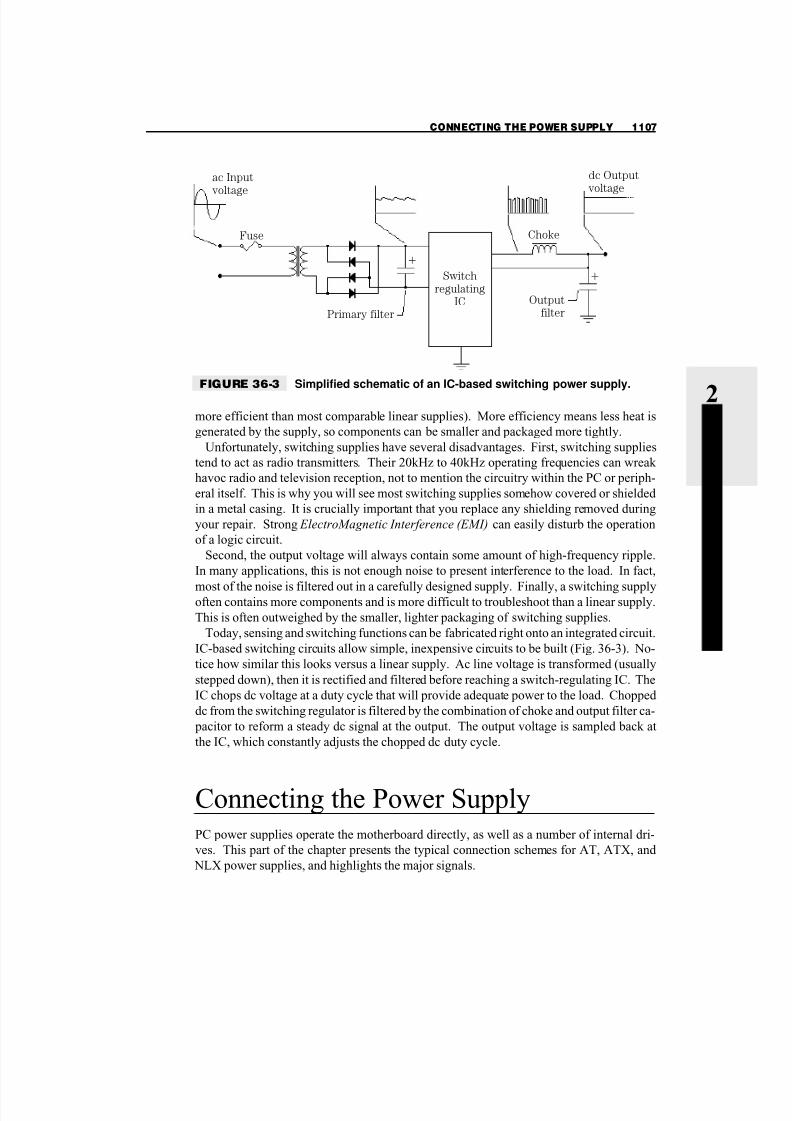
ATX/NLX-STYLE POWER CONNECTIONS
Although ATX and NLX form-factor systems now constitute the majority of new systems
entering service, their power requirements are remarkably similar. The ATX/NLX power
supply provides five voltages to the motherboard (+5 Vdc, –5 Vdc, +12 Vdc, –12 Vdc, and
+3.3 Vdc) through a 20-pin connector (Fig. 36-5). The +3.3-Vdc supply is added to support
the growing base of “low-voltage logic” appearing in the PC. Older AT-style motherboards
also incorporate low-voltage logic, but require an on-board voltage regulator to supply the
+3.3 Vdc, rather than the power supply. The signals can be identified by their colors:
s Black Gnd
s Blue –12 Vdc
s Brown 3.3 V sense
s Gray Power OK
s Green PS-ON
s Orange +3.3 Vdc
s Purple 5 VSB
s Red +5 Vdc
s White –5 Vdc
s Yellow +12 Vdc
In addition to the actual voltages feeding the motherboard, several logic signals are used
to control power:
PS-ON PS-ON is an active-low signal that turns on all of the main power outputs (+3.3
Vdc, +5 Vdc, –5 Vdc, +12 Vdc, and –12 Vdc). When this signal is held high (logic 1) or
left open-circuited, the power-supply outputs should be off. In effect, this is the signal that
allows “soft control” of the system power.
CONNECTING THE POWER SUPPLY 1109
2 S Y S T E M DAT A
AND
T R O UBL E
S H O OT I N G

8/3/2019 Switching p Supplies
http://slidepdf.com/reader/full/switching-p-supplies 7/12
5VSB 5VSB is a “standby voltage” source that can be used to power circuits that require
power input during the powered-down state. The 5VSB pin should deliver 5 Vdc (+/- 5%)
at a minimum of 10 mA for PC board circuits to operate.
PW-OK PW-OK (Power OK) is a “power good” signal and should be set at logic 1 by the
power supply to indicate that the +5-Vdc and +3.3-Vdc outputs are above the undervolt-
age thresholds of the power supply.
OPTIONAL ATX/NLX POWER CONNECTOR
The ATX and NLX form-factor specifications also provide for an optional 6-pin power
connector (Fig. 36-6). Each signal adds a certain amount of versatility to the ATX/NLX
system. You can identify the optional power connector signals by their wire colors:
s White FanM
s White/blue stripe FanC
s White/brown stripe 3.3-V sense
s White/red stripe 1394V
s White/black stripe 1394R
1110 SWITCHING POWER SUPPLIES
3.3Vdc
3.3Vdc
Gnd
5Vdc
Gnd
5Vdc
Gnd
Power OK
5VSB
12Vdc
3.3Vdc
12Vdc
Gnd
PS ON
Gnd
Gnd
Gnd
5Vdc
5Vdc
5Vdc
11 1
12 2
13 3
14 4
15 5
16 6
17 7
18 8
19 9
20 10FIGURE 36-5 ATX/NLX-style mother-
board power connector.

8/3/2019 Switching p Supplies
http://slidepdf.com/reader/full/switching-p-supplies 8/12
FanM signal The FanM signal is an open collector, 2-pulse per revolution tachometer
signal from the power-supply fan. This signal allows the system to monitor the power sup- ply for fan speed or failures. If this signal is not implemented on the motherboard, it
should not impact the power-supply function.
FanC signal The FanC signal is an optional fan-speed and shutdown-control signal.
The fan speed and shutdown are controlled by a variable voltage on this pin. This signal
allows the system to request control of the power supply fan from full speed to off. The
control circuit on the motherboard should supply voltage to this pin from +12 Vdc to 0
Vdc for the fan-control request.
3.3-V sense line A remote 3.3-V sense line can be added to the optional connector to
allow for accurate control of the 3.3-Vdc line directly at motherboard loads.
1394V pin This pin on the optional connector allows for implementation of a segregated voltage supply rail for use with unpowered IEEE-1394 (“fire wire”) solutions. The power
derived from this pin should be used to power only 1394 connectors (unregulated any-
where from 8 to 40 V).
1394R pin The 1394R pin provides an isolated ground path for unpowered IEEE-1394
(“fire wire”) implementations. This ground should be used only for 1394 connections, and
should be fully isolated from other ground planes in the system.
VOLTAGE TOLERANCES
If you pursue power-supply testing or troubleshooting at any level, you’re going to need to
test the output voltages. One important aspect of voltage measurements that are often
overlooked by novice technicians is the idea of “voltage tolerance.” Voltage outputs arerarely exact, and might vary from their rated value by as much as 5% (often 3 to 4% for the
+3.3-Vdc output). For example, a +5-Vdc output might actually read between +4.75 Vdc
and +5.25 Vdc, and a +12-Vdc output might read from +11.4 Vdc to +12.6 Vdc. As long
as the measured voltage is within a reasonable tolerance, the output should be considered
good. If the measured voltage strays outside of this reasonable tolerance (usually to the
CONNECTING THE POWER SUPPLY 1111
2 S Y S T E M DAT A
AND
T R O UBL E
S H O OT I N G
Fan M
Fan C
3.3V sense
1394R
1394V
Reserved
1
2
3
4
5
6FIGURE 36-6 Optional ATX/NLX
motherboard power
connector.
8/3/2019 Switching p Supplies
http://slidepdf.com/reader/full/switching-p-supplies 9/12
low side), chances are that the output is being overloaded by excessive devices. If the out-
put measures extremely low (or is absent) chances are that the output (and the power sup- ply) is defective. You can then choose to repair or replace the power supply.
Troubleshooting SwitchingPower SuppliesTroubleshooting a switching power supply can be a complex and time-consuming task.
Although the operation of rectifier and filter sections are reasonably straightforward, sens-
ing/switching circuits can be complex oscillators that are difficult to follow without a
schematic. Sub-assembly replacement of dc switching supplies is quite common.
TIPS FOR POWER-SUPPLY SERVICE
Power and power-supply problems can manifest themselves in a stunning variety of ways,
but the following tips should help you to stay out of trouble:
s Power-supply cooling is important—keep the vent openings and fan blades clean.
s Be sure that the line-voltage switch (120/220 Vac) is set correctly for your region.
s Verify that the power-supply connectors are attached to the motherboard and drives se-
curely.
s Remember that for AT-style power connections, the “black wires go together.”
s Do not use a Y splitter to split power from a HDD (avoid Y splitters entirely, if possible).
s Some Y splitters are wired improperly. If you have trouble with a device after installing
a Y splitter, check the splitter or try powering the device directly.s Voltage tolerances are usually ±5% (±4% for 3.3 Vdc), so be sure that each output is
within tolerance.
s If you experience erratic system behavior after adding a new device, this can be the re-
sult of an overload. Try removing the device.
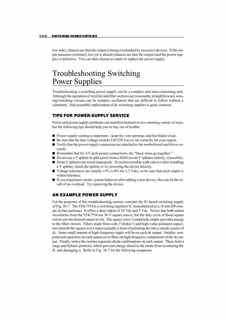
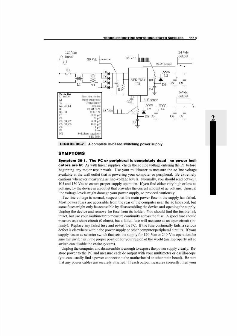
AN EXAMPLE POWER SUPPLY
For the purposes of this troubleshooting section, consider the IC-based switching supply
of Fig. 36-7. The STK7554 is a switching regulator IC manufactured as a 16-pin SIP (sin-
gle in-line package). It offers a dual output of 24 Vdc and 5 Vdc. Notice that both output
waveforms from the STK7554 are 38-V square waves, but the duty cycle of those square
waves sets the desired output levels. The square wave’s amplitude simply provides energy
to the filter circuits. Filters made from coils (“chokes”) and high-value polarized capaci-tors smooth the square-wave input (actually a form of pulsating dc) into a steady source of
dc. Some small amount of high-frequency ripple will be on each dc output. Smaller, non-
polarized capacitors on each output act to filter out high-frequency components of the dc out-
put. Finally, notice the resistor-capacitor-diode combinations on each output. These form a
surge and flyback protector, which prevents energy stored in the choke from re-entering the
IC and damaging it. Refer to Fig. 36-7 for the following symptoms.
1112 SWITCHING POWER SUPPLIES
8/3/2019 Switching p Supplies
http://slidepdf.com/reader/full/switching-p-supplies 10/12
SYMPTOMS
Symptom 36-1. The PC or peripheral is completely dead—no power indi-
cators are lit As with linear supplies, check the ac line voltage entering the PC before
beginning any major repair work. Use your multimeter to measure the ac line voltage
available at the wall outlet that is powering your computer or peripheral. Be extremely
cautious whenever measuring ac line-voltage levels. Normally, you should read between
105 and 130 Vac to ensure proper-supply operation. If you find either very high or low ac
voltage, try the device in an outlet that provides the correct amount of ac voltage. Unusual
line voltage levels might damage your power supply, so proceed cautiously.
If ac line voltage is normal, suspect that the main power fuse in the supply has failed.
Most power fuses are accessible from the rear of the computer near the ac line cord, but
some fuses might only be accessible by disassembling the device and opening the supply.
Unplug the device and remove the fuse from its holder. You should find the fusible link
intact, but use your multimeter to measure continuity across the fuse. A good fuse should
measure as a short circuit (0 ohms), but a failed fuse will measure as an open circuit (in-
finity). Replace any failed fuse and re-test the PC. If the fuse continually fails, a serious
defect is elsewhere within the power supply or other computer/peripheral circuits. If your
supply has an ac selector switch that sets the supply for 120-Vac or 240-Vac operation, besure that switch is in the proper position for your region of the world (an improperly set ac
switch can disable the entire system).
Unplug the computer and disassemble it enough to expose the power supply clearly. Re-
store power to the PC and measure each dc output with your multimeter or oscilloscope
(you can usually find a power connector at the motherboard or other main board). Be sure
that any power cables are securely attached. If each output measures correctly, then your
TROUBLESHOOTING SWITCHING POWER SUPPLIES 1113
2 S Y S T E M DAT A
AND
T R O UBL E
S H O OT I N G
120 Vac
input
F1
39 Vdc 38 Vdc
24 Vdc
output
24-V sense
L1 T1
D1
D2
D3
D4
C1R1
STK 7554
IC1
C25-V sense
L2 L4
C5 C6 C7D5
R2
C3
C4
C8 C9R3
L3
D6
38 Vdc
5-Vdc
outputParts listD1 to D6
L1
T1
L2, L3, L4
R1
R2, R3
C1
C2C3, C4, C7
C5, C6, C8
C9
F1
IC1
Rectifier diodes
Surge supressor
Transformer
Chokes
10 k 1 / 2 W
47 1 W
6000 F
22 F0.01 F
1000 F
1 F
Fuse
Switching regulator
STK 7554
FIGURE 36-7 A complete IC-based switching power supply.

8/3/2019 Switching p Supplies
http://slidepdf.com/reader/full/switching-p-supplies 11/12
trouble lies outside of the supply—a key circuit has failed elsewhere in the device. You
can try a POST board or diagnostic to trace the specific problem further. A low outputvoltage is suggestive of a problem within the supply itself. Check each connector and all
interconnecting wiring leading to or from the supply. Remember that many switching sup-
plies must be attached to a load for proper switching to occur. If the load circuit is dis-
connected from its supply, the voltage signal could shutdown or oscillate wildly.
If the supply outputs continue to measure incorrectly with all connectors and wiring in-
tact, chances are that your problem is inside the supply. With a linear supply, begin test-
ing at the output, then work back toward the ac input. For a switching supply, you should
begin testing at the ac input, then work toward the defective output.
Measure the primary ac voltage applied across the transformer (T1). Use extreme cau-
tion when measuring high-voltage ac. You should read approximately 120 Vac for Fig.
36-7. If voltage has been interrupted in that primary circuit, the meter will read 0 Vac.
Check the primary circuit for any fault that might interrupt power. Measure secondary ac
voltage supplying the rectifier stage. It should read higher than the highest output voltagethat you expect. For the example of Fig. 36-7, the highest expected dc output is 24 V, so
ac secondary voltage should be several volts higher than this. The example shows this as
28 Vac. If primary voltage reads correctly and secondary voltage does not, an open circuit
might be in the primary or secondary transformer winding. Try replacing the transformer.
Next, check the pre-switched dc voltage supplying the switching IC. Use your multi-
meter or oscilloscope to measure this dc level. You should read approximately the peak
value of whatever secondary ac voltage you just measured. For Fig. 36-7, a secondary
voltage of 28 Vac should yield a dc voltage of about (28 Vac RMS ( 1.414) 39 Vdc. If this
voltage is low or non-existent, unplug ac from the supply and check each rectifier diode,
then inspect the filter capacitor.
Use your oscilloscope to measure each chopped dc output signal. You should find a
high-frequency square wave at each output (20kHz to 40kHz) with an amplitude approxi-
mately equal to the pre-switched dc level (38 to 39 volts in this case). Set your oscillo-scope to a time base of 5 or 10 S/DIV and start your VOLTS/DIV setting at 10
VOLTS/DIV. Once you have established a clear trace, adjust the time base and vertical
sensitivity to optimize the display.
If you do not read a chopped dc output from the switching IC, either the IC is defective
or one (or more) of the polarized output filter capacitors might be shorted. Unplug the PC
and inspect each questionable filter capacitor. Replace any capacitors that appear shorted.
As a general rule, filter capacitors tend to fail more readily in switching supplies than in
linear supplies because of high-frequency electrical stress and the smaller physical size of
most switching-supply components. If all filter capacitors check out correctly, replace the
switching IC. Use care when desoldering the old regulator. Install an IC socket (if possi-
ble) to prevent repeat soldering work, then just plug in the new IC. If you do not have the
tools to perform this work (or the problem persists), replace the power supply outright.
Symptom 36-2. Supply operation is intermittent—device operation cuts
in and out with the supply Inspect the ac line voltage into your printer. Be sure that
the ac line cord is secured properly at the wall outlet and printer. Be sure that the power
fuse is installed securely. If the PC/peripheral comes on at all, the fuse has to be intact.
Unplug the device and expose your power supply. Inspect every connector or intercon-
1114 SWITCHING POWER SUPPLIES

8/3/2019 Switching p Supplies
http://slidepdf.com/reader/full/switching-p-supplies 12/12
necting wire leading into or out of the supply. A loose or improperly installed connector
can play havoc with the system’s operation. Pay particular attention to any output con-nections. In almost all cases, a switching power supply must be connected to its load cir-
cuit in order to operate. Without a load, the supply might cut out or oscillate wildly.
In many cases, intermittent operation might be the result of a PC board problem. PC
board problems are often the result of physical abuse or impact, but they can also be
caused by accidental damage during a repair. Lead pull-through occurs when a wire or
component lead is pulled away from its solder joint, usually through its hole in the PC
board. This type of defect can easily be repaired by re-inserting the pulled lead and prop-
erly re-soldering the defective joint. Trace breaks are hairline fractures between a solder
pad and its printed trace. Such breaks can usually render a circuit inoperative, and they are
almost impossible to spot without a careful visual inspection. Board cracks can sever any
number of printed traces, but they are often very easy to spot. The best method for repair-
ing trace breaks and board cracks is to solder jumper wires across the damage between two
adjacent solder pads. You could also simply replace the power supply outright.Some forms of intermittent failures are time or temperature related. If your system
works just fine when first turned on, but fails only after a period of use, then spontaneously
returns to operation later on (or after it has been off for a while), you might be faced with
a thermally intermittent component—a component might work when cool, but fail later on
after reaching or exceeding its working temperature. After a system quits under such cir-
cumstances, check for any unusually hot components. Never touch an operating circuit
with your fingers—injury is almost certain. Instead, smell around the circuit for any trace
of burning semiconductor or unusually heated air. If you detect an overheated component,
spray it with a liquid refrigerant. Spray in short bursts for the best cooling. If normal op-
eration returns, then you have isolated the defective component. Replace any components
that behave intermittently. If operation does not return, test any other unusually warm
components. If problems persist, replace the entire power supply outright.
Further StudyThis concludes the material for Chapter 36. Be sure to review the glossary and chapter
questions on the accompanying CD. If you have access to the Internet, take a look at some
of these power-supply resources:
UL (Underwriter’s Laboratories): http://www.ul.com/
TUV (German Standards): http://www.tuv.com/
Astec: http://www.astec.com/
PC Power and Cooling: http://www.pcpowercooling.com
Amtrade: http://www.amtrade.com
FURTHER STUDY 1115
2 S Y S T E M DAT A
AND
T R O UBL E
S H O OT I N G